Embed Size (px)
Citation preview
ABB AB / Jokab Safety Varlabergsvägen 11, SE-434 39 Kungsbacka, Sweden www.abb.com/jokabsafety
Original instructions
INCA-1 Emergency stop for enclosure installation
INCA-1S Safety stop for enclosure installation
2TLC172175M0201, rev. C 2 www.abb.com/jokabsafety 2013-02-19
Read and understand this document Please read and understand this document before using the products. Please consult your ABB/JOKAB SAFETY representative if you have any questions or comments.
WARRANTY
ABB/JOKAB SAFETY’s exclusive warranty is that the products are free from defects in materials and workmanship for a period of one year (or other period if specified) from date of sale by ABB/JOKAB SAFETY.
ABB/JOKAB SAFETY MAKES NO WARRANTY OR REPRESENTATION, EXPRESSED OR IMPLIED, REGARDING NON-INFRINGEMENT, MERCHANTABILITY, OR FITNESS FOR PARTICULAR PURPOSE OF THE PRODUCTS, ANY BUYER OR USER ACKNOWLEDGES THAT THE BUYER OR USER ALONE HAS DETERMINED THAT THE PRODUCTS WILL SUITABLY MEET THE REQUIREMENTS OR THEIR INTENDED USE. ABB/JOKAB SAFETY DISCLAIMS ALL OTHER WARRANTIES, EXPRESSED OR IMPLIED.
LIMITATIONS OF LIABILITY
ABB/JOKAB SAFETY SHALL NOT BE RESPONSIBLE FOR SPECIAL, INDIRECT, OR CONSEQUENTIAL DAMAGES, LOSS OF PROFITS OR COMMERCIAL LOSS IN ANY WAY CONNECTED WITH THE PRODUCTS, WHETHER SUCH CLAIM IS BASED ON CONTRACT, WARRANTY, NEGLIGENCE, OR STRICT LIABILITY.
In no event shall responsibility of ABB/JOKAB SAFETY for any act exceed the individual price of the product on which liability asserted.
IN NO EVENT SHALL ABB/JOKAB SAFETY BE RESPONSIBLE FOR WARRANTY, REPAIR, OR OTHER CLAIMS REGARDING THE PRODUCTS UNLESS ABB/JOKAB SAFETY’S ANALYSIS CONFIRMS THAT THE PRODUCTS WERE PROPERLY HANDLED, STORED, INSTALLED, AND MAINTAINED AND NOT SUBJECT TO ABUSE, MISUSE, OR INAPPROPRIATE MODIFICATION OR REPAIR.
SUITABILITY FOR USE
ABB/JOKAB SAFETY shall not be responsible for conformity with any standards, codes, or regulations that apply to the combination of products in the customer’s application or use of the product. At the customer’s request, ABB/JOKAB SAFETY will provide applicable third party certification documents identifying ratings and limitations of use that apply to the products. This information by itself is not sufficient for a complete determination of the suitability of the products in combination with the end product, machine, system, or other application or use.
The following are some examples of applications for which particular attention must be given. This is not intended to be an exhaustive list of all possible uses of the products, nor is it intended to imply that the uses listed may be suitable for the products:
Outdoor use, uses involving potential chemical contamination or electrical interference, or conditions or uses not described in this document.
Nuclear energy control systems, combustion systems, railroad systems, aviation systems, medical equipment, amusement machines, vehicles, and installations subject to separate industry or government regulations.
Systems, machines, and equipment that could present a risk to life or property.
Please know and observe all prohibitions of use applicable to the products.
NEVER USE THE PRODUCTS FOR AN APPLICATION INVOLVING SERIOUS RISK TO LIFE OR PROPERTY WITHOUT ENSURING THAT THE SYSTEM AS A WHOLE HAS BEEN DESIGNED TO ADDRESS THE RISKS, AND THAT THE ABB/JOKAB SAFETY PRODUCT IS PROPERLY RATED AND INSTALLED FOR THE INTENDED USE WITHIN THE OVERALL EQUIPMENT OR SYSTEM.
PERFORMANCE DATA
While every effort has been taken to ensure the accuracy of the information contained in this manual ABB/JOKAB SAFETY cannot accept responsibility for errors or omissions and reserves the right to make changes and improvements without notice. Performance data given in this document is provided as a guide for the user in determining suitability and does not constitute a warranty. It may represent the result of ABB/JOKAB SAFETY’S test conditions, and the users must correlate it to actual application requirements. Actual performance is subject to the ABB/JOKAB SAFETY Warranty and Limitations of Liability.
2TLC172175M0201, rev. C 3 www.abb.com/jokabsafety 2013-02-19
Table of Contents 1 Introduction ......................................................................................................................................... 4
Scope ........................................................................................................................................................................ 4
Audience ................................................................................................................................................................... 4
Prerequisites ............................................................................................................................................................. 4
Special notes ............................................................................................................................................................ 4
2 Overview .............................................................................................................................................. 5
General description ................................................................................................................................................... 5
Safety regulations ..................................................................................................................................................... 5
3 Connections ........................................................................................................................................ 6
Connection examples ............................................................................................................................................... 6
4 Installation and maintenance ............................................................................................................. 7
Installation precautions ............................................................................................................................................. 7
Maintenance ............................................................................................................................................................. 7
5 Operation ............................................................................................................................................. 8
LED indication ........................................................................................................................................................... 8
6 Model overview .................................................................................................................................... 9
Accessories ............................................................................................................................................................... 9
7 Technical data ................................................................................................................................... 10
Dimensions ............................................................................................................................................................. 11
8 EC Declaration of conformity ........................................................................................................... 12
2TLC172175M0201, rev. C 4 www.abb.com/jokabsafety 2013-02-19
1 Introduction Scope The purpose of these instructions is to describe the emergency stop INCA 1and safety stop INCA-1S, and to provide the necessary information required for installation and operation.
Audience This document is intended for authorized installation personnel.
Prerequisites It is assumed that the reader of this document has knowledge of the following:
• Basic knowledge of ABB/Jokab Safety products.
• Knowledge of machine safety.
Special notes Pay attention to the following special notes in the document:
Warning! Danger of severe personal injury! An instruction or procedure which, if not carried out correctly, may result in injury to the technician or other personnel.
Caution! Danger of damage to the equipment! An instruction or procedure which, if not carried out correctly, may damage the equipment.
NB: Notes are used to provide important or explanatory information.
2TLC172175M0201, rev. C 5 www.abb.com/jokabsafety 2013-02-19
2 Overview General description INCA 1is an emergency stop device designed for installation in a 22.5 mm slot in an apparatus enclosure.
There is an INCA-1S with black stop button, which is intended for use as a safety stop.
Warning! The emergency stop INCA normally needs to be complemented with other safety functions such as interlocking guards etc. Refer to risk analysis.
NB: The emergency stop (INCA-1) should not be used as normal stop of the machine, only in case of emergency.
Safety regulations
Warning!
Carefully read through this entire manual before using the device.
The devices shall be installed by a trained electrician following the Safety regulations, standards and the Machine directive.
Failure to comply with instructions, operation that is not in accordance with the use prescribed in these instructions, improper installation or handling of the device can affect the safety of people and the plant.
For installation and prescribed use of the product, the special notes in the instructions must be carefully observed and the technical standards relevant to the application must be considered.
In case of failure to comply with the instructions or standards, especially when tampering with and/or modifying the product, any liability is excluded.
2TLC172175M0201, rev. C 6 www.abb.com/jokabsafety 2013-02-19
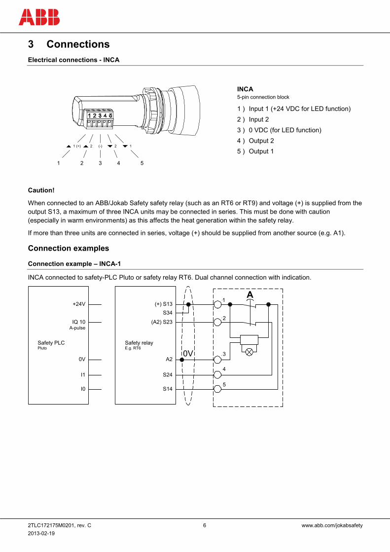
3 Connections Electrical connections - INCA
Caution!
When connected to an ABB/Jokab Safety safety relay (such as an RT6 or RT9) and voltage (+) is supplied from the output S13, a maximum of three INCA units may be connected in series. This must be done with caution (especially in warm environments) as this affects the heat generation within the safety relay.
If more than three units are connected in series, voltage (+) should be supplied from another source (e.g. A1).
Connection examples
Connection example – INCA-1
INCA connected to safety-PLC Pluto or safety relay RT6. Dual channel connection with indication.
0V
1
2
4
3
5
+24V
IQ 10A-pulse
0V
I1
I0
(+) S13S34
(A2) S23
A2
S24
S14
A
Safety PLCPluto
Safety relayE.g. RT6
1 2 3 4 5
1 (+) 2 12(-)
INCA 5-pin connection block
1 ) Input 1 (+24 VDC for LED function) 2 ) Input 2 3 ) 0 VDC (for LED function) 4 ) Output 2 5 ) Output 1
2TLC172175M0201, rev. C 7 www.abb.com/jokabsafety 2013-02-19
4 Installation and maintenance Installation precautions First mount INCA in the apparatus enclosure slot and then attach and fasten the M22 nut. Finally, attach the connection block.
Warning! All the safety functions must be tested before starting up the system.
Maintenance
Warning!
The safety functions and the mechanics shall be tested regularly, at least once every year to confirm that all the safety functions are working properly.
In case of breakdown or damage to the product, contact the nearest ABB/Jokab Safety Service Office or reseller. Do not try to repair the product yourself since it may accidentally cause permanent damage to the product, impairing the safety of the device which in turn could lead to serious injury to personnel.
2TLC172175M0201, rev. C 8 www.abb.com/jokabsafety 2013-02-19
5 Operation LED indication LED Indication Description
LED on button
Green Safety device OK. Safety circuit closed.
OFF Safety circuit interrupted (when an emergency stop actuator is pressed down, all following units in the safety circuit lose the LED function).
Red Safety device actuator pressed down. Safety circuit interrupted.

2TLC172175M0201, rev. C 9 www.abb.com/jokabsafety 2013-02-19
6 Model overview Type Article number Description
INCA 1 2TLA030054R0100 Emergency stop, red button, 5-pin connection block
INCA 1S 2TLA030054R0300 Safety stop, black button, 5-pin connection block
Accessories Type Article number Description
Yellow surround 2TLA030054R0400 Yellow surround for emergency stop button.
Emergency stop sign 2TLA030054R0500 Ø22.5 mm, Swedish, Danish, Finnish
Emergency stop sign 2TLA030054R0600 Ø22.5 mm, English, French, German
The Jokab Safety branded product with articlenumber beginning with 2TLJ is fully compatible with the ABB branded product with articlenumber beginning with 2TLA.
Yellow surround for emergency stop button Article number: 2TLA030054R0400
Emergency stop sign Ø22.5 mm Article number: S, D, F: 2TLA030054R0500 E, F, G: 2TLA030054R0600
2TLC172175M0201, rev. C 10 www.abb.com/jokabsafety 2013-02-19
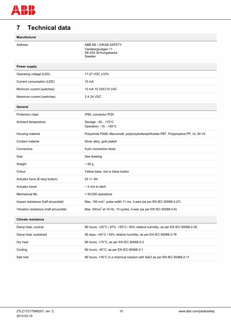
7 Technical data Manufacturer
Address ABB AB / JOKAB SAFETY Varlabergsvägen 11 SE-434 39 Kungsbacka Sweden
Power supply
Operating voltage (LED) 17-27 VDC ±10%
Current consumption (LED) 15 mA
Minimum current (switches) 10 mA 10 VDC/10 VAC
Maximum current (switches) 2 A 24 VDC
General
Protection class IP65, connector IP20
Ambient temperature Storage: -30…+70°C Operation: -10…+55°C
Housing material Polyamide PA66, Macromelt, polybutylenterephthalate PBT, Polypropene PP, UL 94 V0
Contact material Silver alloy, gold plated
Connectors 5-pin connection block
Size See drawing
Weight ~ 45 g
Colour Yellow base, red or black button
Actuator force (E-stop button) 22 +/- 4N
Actuator travel ~ 4 mm to latch
Mechanical life > 50,000 operations
Impact resistance (half sinusoidal) Max. 150 m/s2, pulse width 11 ms, 3-axis (as per EN IEC 60068-2-27)
Vibration resistance (half sinusoidal) Max. 50m/s2 at 10 Hz, 10 cycles, 3-axis (as per EN IEC 60068-2-6)
Climate resistance
Damp heat, cyclical 96 hours, +25°C / 97%, +55°C / 93% relative humidity, as per EN IEC 60068-2-30
Damp heat, sustained 56 days, +40°C / 93% relative humidity, as per EN IEC 60068-2-78
Dry heat 96 hours, +70°C, as per EN IEC 60068-2-2
Cooling 96 hours, -40°C, as per EN IEC 60068-2-1
Salt mist 96 hours, +35°C in a chemical solution with NaCl as per EN IEC 60068-2-11
2TLC172175M0201, rev. C 11 www.abb.com/jokabsafety 2013-02-19
Safety / Harmonized Standards
Conformity European Machinery Directive 2006/42/EC
EN ISO 12100:2010, EN ISO 13849-1:2008/AC:2009, EN 60204-1:2007+A1, EN ISO 13850:2008
EN ISO 13849-1 Performance level: Up to PL e, category 4
B10d: 6 050
Certificates Inspecta
NB: A safety function with an emergency stop INCA 1 can achieve Cat. 4/PL e according to EN ISO 13849-1 only when a single INCA unit is connected to the control unit (safety-PLC or safety relay) in a dual channel configuration.
Warning! The maximum number of operations (cycles) for the emergency stop INCA is 6050 operations.
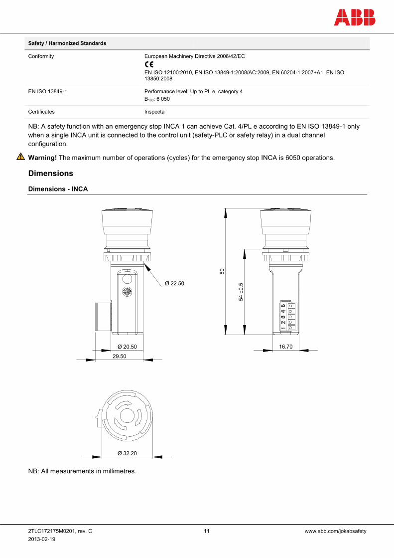
Dimensions
Dimensions - INCA
Ø 20.50
Ø 22.50
Ø 32.20
16.70
80
54±0
.5
29.50
NB: All measurements in millimetres.
2TLC172175M0201, rev. C 12 www.abb.com/jokabsafety 2013-02-19
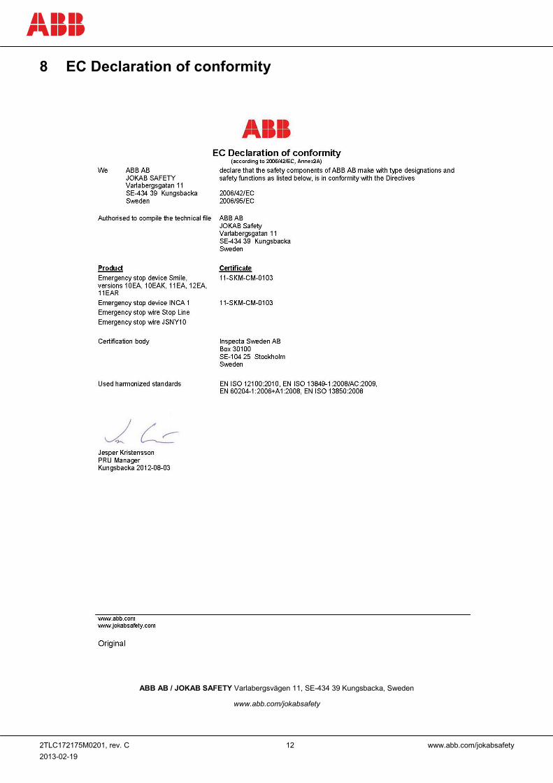
8 EC Declaration of conformity
ABB AB / JOKAB SAFETY Varlabergsvägen 11, SE-434 39 Kungsbacka, Sweden
www.abb.com/jokabsafety