Embed Size (px)
Citation preview

IN SITU BIOPRINTING OF THE SKIN
BY
KYLE W. BINDER
A Dissertation Submitted to the Graduate Faculty of
WAKE FOREST UNIVERSITY GRADUATE SCHOOL OF ARTS AND SCIENCES
in Partial Fulfillment of the Requirements
for the Degree of
DOCTOR OF PHILOSOPHY
Molecular Genetics and Genomics
May 2011
Winston-Salem, North Carolina
Copyright Kyle W. Binder 2011
Approved By:
James J. Yoo, M.D., Ph.D., Advisor
Shay S. Soker, Ph.D., Chair
Mark Lively, Ph.D.
James H. Holmes, M.D.
Stephen Walker, Ph.D.

ii
ACKNOWLEDGEMENTS
This dissertation is dedicated to my family. To my father, William, for teaching
me the values of hard work and dedication. To my mother, Ellen, for her unfailing love
and support. To my brother, Matthew, for his perseverance and loyalty. To my sister,
Melanie, for her support and for always being available to listen. To my brother,
Christian, for inspiring me with maturity beyond his years.
To my dissertation committee, for teaching me to be a scientist. To Dr. James
Yoo, for presenting me with the opportunity of a lifetime and advising me. To the Armed
Forces Institutes of Regenerative Medicine, for providing funding and allowing me the
opportunity to help heal our wounded warriors.
To the biofabrication team with whom I have worked the last several years. To
Dr. Tao Xu, for introducing me to the field of biofabrication. To Dennis Dice, whose
expertise in electrical engineering made this project happen. To Dr. Weixin Zhao, for his
assistance in procedures. To Josh Tan, whose expertise in imaging allowed us to
overcome many of the obstacles we faced while building the skin bioprinter. To Dr.
Hyun-Wook Kang, for his assistance in procedures and for writing software to parse
scanned models of the wound surface. To Shengli Zhang, for his assistance in
procedures. To Paul Scarpinato, for providing expertise in mechanical engineering and
helping design the clinical prototype skin bioprinter. To AJ Allen, for being the best
student I have ever had and helping to shoulder the load.
To all the staff at the Wake Forest Institute for Regenerative Medicine who have
assisted me over the years. To Cathy Mathis, who taught me histology and spent many

iii
late nights helping me section and stain slides. Without her I would not have been able to
complete this project. To Dr. Erin Mitchell, for her patience and assistance with the
animal research. To Cindy Andrews, for assisting with surgeries. To Tammy
Cockerham and Renae Hall, for their assistance with the large animal studies. To all my
friends and co-workers, I thank you with all my heart. You will always have my
gratitude.

iv
TABLE OF CONTENTS
LIST OF ILLUSTRATIONS .............................................................................................. v
LIST OF ABBREVIATIONS .......................................................................................... viii
ABSTRACT ........................................................................................................................ x
INTRODUCTION .............................................................................................................. 1
OVERVIEW OF BIOPRINTING..................................................................................... 41
DEVELOPMENT OF A NOVEL DEVICE FOR IN SITU BIOPRINTING OF THE
SKIN ................................................................................................................................. 68
IN SITU BIOPRINTING OF THE SKIN IN A MURINE MODEL.............................. 101
IN SITU BIOPRINTING OF THE SKIN IN A PRECLINICAL MODEL ................... 122
CONCLUSIONS AND FUTURE WORK ..................................................................... 160
BIOPRINTER V2.0 SOFTWARE.................................................................................. 173
SKIN DELIVERY SYSTEM SOFTWARE ................................................................... 323
CURRICULUM VITAE ................................................................................................. 444

v
LIST OF ILLUSTRATIONS
Figure 1-1. Structure of normal human skin. ..................................................................... 2
Figure 2-1. Schematic representation of three different inkjet printing methods. ........... 44
Figure 2-2. HP Deskjet 640c series inkjet printer modified to print without paper. ........ 50
Figure 2-3. Visual C++ code for programmatically creating a series of lines for
vasculature bioprinting...................................................................................................... 52
Figure 2-4. Schematic diagram of in situ skin bioprinter. ............................................... 54
Figure 2-5. Schematic drawing of the postulated mechanism for inkjet-induced gene
transfection. ....................................................................................................................... 57
Figure 2-6. Effects of the printing parameters and conditions on gene transfection. ...... 58
Figure 2-7. In vitro gene printing. .................................................................................... 59
Figure 3-1. Hardware for the prototype skin bioprinter. .................................................. 71
Figure 3-2. Schematic diagram of MC9S08JM60 microprocessor for bioprinting
applications. ...................................................................................................................... 75
Figure 3-3. Schematic diagram of the motor controllers for bioprinting applications. ... 76
Figure 3-4. Schematic diagram of the display and control driver for bioprinting
applications. ...................................................................................................................... 77
Figure 3-5. Schematic representation of three-tier architecture for Bioprinter v2.0. ...... 78
Figure 3-6. Main window of Bioprinter v2.0 with MRI image displayed. ...................... 80
Figure 3-7. Main window of Bioprinter v2.0 with grid displayed over MRI image. ...... 83
Figure 3-8. Main window of Bioprinter v2.0 with edges of MRI image displayed. ....... 84

vi
Figure 3-9. Main window of Bioprinter v2.0 with outer edges of MRI image defined in
memory. ............................................................................................................................ 85
Figure 3-10. Main window of Bioprinter v2.0 with MRI image overlaid with both edges
and 16x16 pixel grid. ........................................................................................................ 86
Figure 3-11. Main window of Bioprinter v2.0 with Print Controls menu displayed. ...... 88
Figure 3-12. Automatic printing menu of Bioprinter v2.0............................................... 90
Figure 3-13. Schematic representation of the Organ object. ........................................... 93
Figure 4-1. Proof-of-concept experiment with prelabeled fibroblasts and keratinocytes.
......................................................................................................................................... 108
Figure 4-2. Analysis of wound sizes over 6 weeks. ....................................................... 109
Figure 4-3. Gross examination of printed skin. ............................................................. 110
Figure 4-4. Masson’s Trichrome examination of skin. .................................................. 112
Figure 4-5. Immunohistochemistry for human cells. ..................................................... 113
Figure 5-1. Concept design of the skin delivery system. ............................................... 125
Figure 5-2. Movement system hardware schematic. ..................................................... 126
Figure 5-3. Skin Delivery System cartridges, printhead, and flow schematic. .............. 127
Figure 5-4. Sample output of laser scanner integrated with skin delivery system. ....... 129
Figure 5-5. Skin delivery system software schematic. .................................................. 130
Figure 5-6. Skin delivery system configuration manager. ............................................. 131
Figure 5-7. Skin delivery system configuration manager for printhead development. . 133
Figure 5-8. Main window of Skin Delivery System with Print Controls menu displayed.
......................................................................................................................................... 135
Figure 5-9. Schematic representation of wound sites in the preclinical model. ............ 143

vii
Figure 5-10. Operation of the skin delivery system. ...................................................... 149
Figure 5-11. Comparison of four different wound treatments over 8 weeks. ................ 151
Figure 5-12. Analysis of wound sizes over 8 weeks. ..................................................... 152
Figure 5-13. Analysis of wound contracture over 8 weeks. .......................................... 154
Figure 5-14. Analysis of wound epithelialization over 8 weeks. ................................... 155
Figure 5-15. Hematoxylin and eosin evaluation of four different wound treatments at 8
weeks............................................................................................................................... 156
Figure 5-16. Histological comparison of four different wound treatments at 8 weeks. 157
Figure 6-1. Concept design of delivery system for the clinical skin bioprinter. ............ 161
Figure 6-2. Clinical prototype software schematic ........................................................ 164

viii
LIST OF ABBREVIATIONS
Ultraviolet UV
Interleukin IL
Tumor necrosis factor TNF
Transforming growth factor TGF
Cyclooxygenase COX
Type 1 helper T cell Th1
Type 2 helper T cell Th2
Natural killer cell NK
Interferon IFN
Extracellular matrix ECM
Connective tissue activating peptide CTAP
Platelet-derived growth factor PDGF
Induced nitric oxide synthase iNOS
Epidermal growth factor EGF
Fibroblast growth factor FGF
Keratinocyte growth factor KGF
Vascular endothelial growth factor VEGF
Total body surface area TBSA
Epidermolysis bullosa EB
Cultured epithelial autograft CEA
Ethylenediaminetetraacetic acid EDTA

ix
Green fluorescent protein GFP
Porcine aortic endothelial cell PAE
Universal serial bus USB
Recommended standard 232 RS232
b Binary
0x Hexadecimal
Joint Photographic Experts Group JPEG
Graphics Interchange Format GIF
Tagged Image File TIF
Portable Network Graphics PNG
Phosphate buffered saline PBS
Hematoxylin and eosin H&E
Analysis of variance ANOVA
Human leukocyte antigen HLA
Dots per inch DPI
Penicillin/Streptomycin/Amphotericin B PSA
4',6-diamidino-2-phenylindole DAPI
Antigen presenting cell APC

x
ABSTRACT
Burn injury is a common source of morbidity and mortality in the battlefield,
comprising 10 to 30% of all casualties. In the civilian population, there are
approximately 500,000 burn injuries requiring treatment each year. Autografts and
commercially available skin products are limited in size and some require a lengthy
preparation time, making them unusable in severe cases that require prompt and
aggressive measures to maintain the lives of wounded patients. Moreover, patient
survival is inversely proportional to the amount of time required to cover and stabilize a
wound. Therefore, a new approach that permits immediate burn wound stabilization with
functional recovery is necessary. We propose a novel treatment that would repair burn
wounds in situ by using cartridge-based bioprinting to precisely deliver skin cells in a
controlled manner in a wound.
The skin bioprinter uses a cartridge based delivery system with a laser scanning
system mounted on a portable XYZ plotting system. The cartridge system is similar to
that used in traditional inkjet printing such that each cell type is loaded into an individual
cartridge in the same way different color inks would be contained in different cartridges.
The data obtained from the laser scanner is pieced together to form a model of the wound
surface. Together, these technologies print skin that can match the skin that is missing
from the wound.
To demonstrate the feasibility of in situ skin printing, the skin bioprinter was used
to bioprint human fibroblasts and keratinocytes directly in a nude mouse wound model.
Wounds repaired using in situ skin cell bioprinting demonstrated up to 3 weeks faster

xi
wound closure compared to negative controls. Printed skin required approximately 10-14
days to organize into skin which is consistent with previous experiments using cell-
spraying techniques. Complete closure of the wounds by 3 weeks was confirmed by
organization of the skin cells with organized dermal collagen and a fully formed
epidermis. Histological analysis demonstrated the presence of human skin cells in the
dermis and epidermis of the new skin.
Based on the results of the murine experiment, the skin bioprinter was upgraded
for preclinical studies in a porcine wound model. Full-thickness excisional wounds made
on the dorsa were imaged with the laser scanning system and repaired using autologous
or allogeneic fibroblasts and keratinocytes. Bioprinted fibroblasts and keratinocytes were
able to close the wound more quickly than negative controls. Autologous keratinocytes
showed evidence of re-epithelialization in the wound center at 2 weeks post-printing.
These areas of epithelialization grew progressively larger until they had covered the
entire wound. Labeled fibroblasts and keratinocytes that were bioprinted in situ were
visible in the center of the wound at 8 weeks.
This dissertation describes the design and use of a novel delivery system for in
situ bioprinting of the skin. The cartridge-based system presented here can be easily
transported from patient to patient and can rapidly print skin constructs consisting of any
cell type or biomaterial that can be packaged into a compatible cartridge. We
successfully regenerated skin in murine and porcine wound models using fibroblasts and
keratinocytes, demonstrating that the concept of in situ skin bioprinting is a viable
technique. This work represents an important new step in burn care for both the civilian
and military populations.

1
CHAPTER 1
INTRODUCTION
1.1. Structure of Skin
The integumentary organ system is one of the most important body structures
both psychologically and physiologically. In most cultures, skin is a primary
communicator during initial interactions with another person. Before any verbal contact
commences, visual cues display a wealth of information about each person. Pigmentation
demonstrates ancestry and can provide information about geographical locations where a
person lives. Pigmentation can also provide information about occupation or potential
leisure activities. Hair color and consistency can belie age. Skin injuries, especially
large wounds, can be readily visible and heavily impact a person's interactions with the
world.
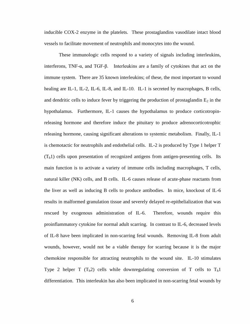
Physiologically, the structures of the skin interact with the environment and
protect the body from numerous environmental factors. Normal skin consists of three
major layers: the hypodermis, dermis, and epidermis (Figure 1-1). The hypodermis
consists mostly of adipose tissue and is the lowest layer of skin lying just above the
underlying muscle layers. This layer of fat provides heat insulation and is a major source
of energy storage in the form of triglycerides. Above the hypodermis lies the dermis,
which consists of reticular and papillary dermis. Reticular dermis contains highly
organized type I collagen and elastic fibers secreted by dermal fibroblasts. These fibers
are organized along specific lines of tension termed Langer's lines. Wounds parallel to

2
Langer's lines heal with less scarring than other wounds. Papillary dermis contains less
organized type I and type III collagen bundles than the reticular dermis. Crucially,
papillary dermis holds the blood vessels and nerves that service the epidermis. The
epidermis does not contain its own blood vessels or nerves. For wound healing, the
importance of the papillary dermis in serving the epidermis means that epidermal cells
cannot survive without this support (Ross & Pawlina, 2003).
The epidermal barrier prevents foreign organisms from entering the body and
provides a barrier to water loss. The epidermis attaches to the dermis through a series of
dermal protrusions into the epidermis that match to epidermal protrusions extending into
the dermis. Dermal protrusions are termed dermal papillae and epidermal protrusions are
rete ridges. The interface between the dermal papillae and rete ridges increases the
surface area available to connect the dermis and epidermis, especially in areas of the skin
that are subject to severe tension. The epidermis is composed of four strata: stratum
basale, stratum spinosum, stratum granulosum, and stratum corneum. The stratum basale
Figure 1-1. Structure of normal human
skin. Reproduced under Title 17, Chapter 1,
Section 105 of the U.S. Code.

3
holds the self-renewing population of keratinocytes that form the bulk of the epidermis.
As keratinocytes grow toward the surface of the skin they shed their nuclei and produce
copious amounts of keratins as well as other constituents of the epidermal barrier. This
process occurs as a controlled apoptosis when keratinocytes leave the stratum basale and
progress through the stratum spinosum, stratum granulosum, and finally stratum
corneum, where the keratinocytes are anucleate. Epidermal turnover occurs every 4
weeks. In addition to keratinocytes, the epidermis also contains Langerhans' cells as
antigen-presenting cells sampling antigens presenting through the skin. Merkel's cells
provide the sensory reception for mechanical stimulation. Furthermore, eccrine glands
derive from the epidermis and play a large role in regulating body temperature through
thermoregulatory sweating (Ross & Pawlina, 2003).
Although skin mainly consists of adipose tissue, dermal fibroblasts, and
keratinocytes, adnexal skin structures such as hair and pigment are vital to the normal
functions of the integumentary system. Hair follicles play important roles in protection
from the outside environment as well as providing exits to the outer skin for structures
within the dermis. Specifically, sebaceous and apocrine glands attach to hair follicles and
produce sebum and pheromones, respectively. Hairs provide mechanosensory input
through bending of the shaft which allows sensation of slight changes in the environment.
A variety of immune cells reside in the follicle including Langerhans’ cells, perifollicular
macrophages, and mast cells. The follicle provides a method of sensing impending
infection and allows the immune system to react to potential pathogens before they gain
access to the body. Follicles also play an important role in wound healing. Cells in the
root sheath proliferate in response to injury and help regenerate the epidermis. This is an

4
important factor when considering coverage and repair of large area wounds because the
ultimate goal is to restore normal skin. Attempts to restore normal skin that ignore the
contribution of follicles to the healing process remove a major factor in skin restoration
(Paus & Cotsarelis, 1999).
Melanocytes reside in the basal layer of the epidermis along with the proliferative
keratinocytes. They produce melanin, a tryptophan-derived lipophilic molecule capable
of penetrating cell membranes in the skin. Melanin has been identified in a large number
of skin-specific regenerative and anti-apoptotic pathways including but not limited to: (1)
stimulation of keratinocyte proliferation; (2) inhibition of apoptosis in cell cycle-
synchronized keratinocytes under serum-free conditions; (3) increased viability in serum-
free-cultured fibroblasts; (4) stimulation of hair shaft elongation in human hair follicles in
vitro at low concentrations and inhibition at high concentrations; (5) protection against
pressure-induced ulcer formation; (6) reduction of thermal skin injury; (7)
thermoregulation of skin blood flow; (8) protection against necrosis, lipid peroxidation,
and reduction of antioxidative enzymes in skin flaps; (9) stronger radical scavenger than
vitamins C and E; (10) increased cell survival of immortalized keratinocytes and ensuring
keratinocyte colony growth under ultraviolet (UV)-induced stress; (11) decrease of
ultraviolet-induced DNA fragmentation; (12) maintenance of mitochondrial membrane
potential in ultraviolet exposed keratinocytes; (13) reduction of caspase 9, 3 and 7
activation; and (14) inhibition of poly(ADP-ribose) polymerase activation (Fischer et al.,
2008). Melanocytes protect the cells of the integumentary system from a variety of
highly damaging environmental factors and are vital to the normal functions of skin.

5
There are dozens of known cell types in the integumentary system, each
performing a specific role to facilitate the various functions of skin. When skin is
damaged, these cells attempt to repair the injury through the astoundingly complex
wound healing process.
1.2. Wound Healing
Wound healing can be divided into three major stages: inflammation,
proliferation, and remodeling.
1.2.1. Hemostasis and Inflammation
The first physiological response to injury is hemostasis by forming a fibrin clot to
stop bleeding. This cascade results in scaffolding for the wound healing process that
contains collagen, platelets, fibronectin, and fibrin. Not only do these components
release a variety of chemotactic factors to attract circulating immunologic cells, the
structure of the clot serves to concentrate these factors in the site of injury and protect
them from immediate degradation. These factors along with signals from the damaged
cells drive the inflammatory phase of wound healing. Chief among these factors are
thromboxane A2, the interleukins (IL), tumor necrosis factor (TNF)-α, and transforming
growth factor (TGF)-β. Thromboxane A2 is potent vasoconstrictor and chemotactic
factor formed from prostaglandin H2 by thromboxane-A synthase present in activated
platelets. Prostaglandin H2 is generated by constitutively expressed cyclooxygenase
(COX)-1 which is inhibited by certain non-steroidal anti-inflammatory compounds.
Many other prostaglandins are expressed after the initial phase of hemostasis by the
6
inducible COX-2 enzyme in the platelets. These prostaglandins vasodilate intact blood
vessels to facilitate movement of neutrophils and monocytes into the wound.
These immunologic cells respond to a variety of signals including interleukins,
interferons, TNF-α, and TGF-β. Interleukins are a family of cytokines that act on the
immune system. There are 35 known interleukins; of these, the most important to wound
healing are IL-1, IL-2, IL-6, IL-8, and IL-10. IL-1 is secreted by macrophages, B cells,
and dendritic cells to induce fever by triggering the production of prostaglandin E2 in the
hypothalamus. Furthermore, IL-1 causes the hypothalamus to produce corticotropin-
releasing hormone and therefore induce the pituitary to produce adrenocorticotrophic
releasing hormone, causing significant alterations to systemic metabolism. Finally, IL-1
is chemotactic for neutrophils and endothelial cells. IL-2 is produced by Type 1 helper T
(Th1) cells upon presentation of recognized antigens from antigen-presenting cells. Its
main function is to activate a variety of immune cells including macrophages, T cells,
natural killer (NK) cells, and B cells. IL-6 causes release of acute-phase reactants from
the liver as well as inducing B cells to produce antibodies. In mice, knockout of IL-6
results in malformed granulation tissue and severely delayed re-epithelialization that was
rescued by exogenous administration of IL-6. Therefore, wounds require this
proinflammatory cytokine for normal adult scarring. In contrast to IL-6, decreased levels
of IL-8 have been implicated in non-scarring fetal wounds. Removing IL-8 from adult
wounds, however, would not be a viable therapy for scarring because it is the major
chemokine responsible for attracting neutrophils to the wound site. IL-10 stimulates
Type 2 helper T (Th2) cells while downregulating conversion of T cells to Th1
differentiation. This interleukin has also been implicated in non-scarring fetal wounds by

7
inhibiting the infiltration of neutrophils and macrophages to the wounds site. The
interleukins represent a complex set of spatial and temporal signals to direct the
inflammatory phase of the wound healing process.
Once the interleukins and other cytokines attract inflammatory cells to the wound
site, TNF-α and TGF-β along with interferon γ (IFN-γ) activate these cells and assist in
laying provisional matrix for wound healing. Neutrophils are the first line of wound
defense and are attracted to IL-1, TNF-α, and TGF-β. These cells adhere to the
remaining extracellular matrix (ECM) using integrin receptors on the cell membrane.
Once in the wound site, neutrophils convert connective tissue-activating peptide III
(CTAP-III) into neutrophil-activating peptide 2 (NAP 2), drawing more neutrophils into
the damaged area. Neutrophils attack invading organisms by phagocytosis and
generation of oxygen free radicals. In addition, they eliminate non-viable ECM by
elaborating a large release of non-specific proteases that overwhelm the natural protease
inhibitors. Finally, neutrophils reduce the inflammatory response by producing
leukotriene A4 and lipoxins. Normally, leukotriene A4 and leukotriene B4 cause
chemotaxis of inflammatory cells as well as increased vascular permeability. However,
in the presence of platelet 12-lipoxygenase leukotriene A4 is converted to lipoxin A4 and
B4. These lipoxins act to reduce inflammation by inhibiting proliferation of neutrophils.
Eventually, neutrophils in the wound site undergo apoptosis and are phagocytized by
macrophages.
Macrophages are the most important cell type involved in initiating the
proliferative wound healing process from the inflammatory phase. Derived from
monocytes that are attracted to the cytokines present in the wound, macrophages are

8
activated by IL-2, TNF-α, and IFN-γ. These signals create a positive feedback that
amplifies the macrophage response to tissue damage. Macrophages release a variety of
growth factors including platelet-derived growth factor (PDGF), TNF-α, and IL-6. These
growth factors and cytokines act on fibroblasts to initiate cell proliferation and ECM
deposition in preparation for production of granulation tissue. The proliferating
fibroblasts also produce a similar cytokine profile that increases the number of
macrophages responding to the injury. Furthermore, IL-1 and TNF-α elicit increased
levels of induced nitric oxide synthase (iNOS) from the macrophages. Nitric oxide is an
effective attack against organisms that are resistant to the oxygen free radicals produced
by the neutrophils, such as Staphylococcus aureus. Nitric oxide combines with free
radicals to form extremely toxic peroxynitrite. In addition, macrophages phagocytize
debris within the wound as well as dead cells, paving the way for new tissue formation.
(Broughton et al., 2006a; Broughton et al., 2006b; Werner & Grose, 2003; Henry &
Garner, 2003; Grose & Werner, 2003).
Hemostasis and inflammation are complex processes that complement each other.
Hemostasis attempts to limit further tissue damage and the subsequent inflammatory
response is initiated by cytokines elicited during the hemostatic process. Both of these
stages prepare the wound bed for proliferation of skin cells and repair of the damaged
tissue.
1.2.2. Proliferation
Proliferation is the second stage of wound healing and is characterized by
formation of granulation tissue. For wounds that do not contain residual epithelial cells,

9
this phase is characterized by fibroblast proliferation into the wound to produce a
preliminary collagen matrix. Keratinocytes at the wound edge begin to divide rapidly
and grow into the wound in an attempt to restore the epithelial barrier to water loss and
infection. Dividing keratinocytes are characterized by a columnar appearance on
histological examination due to expansion of the stratum basale. Proliferation of the
fibroblasts and keratinocytes is marked by production of a variety of growth factors that
are produced in response to the cytokines elicited during the inflammation phase.
Fibroblasts proliferate in response to epidermal growth factors (EGF), fibroblast
growth factors (FGF), and PDGF produced by platelets and macrophages. PDGF is also
produced by activated wound fibroblasts and acts via autocrine and paracrine signaling to
further increase fibroblast proliferation. Signaling via tyrosine kinase receptors, PDGF
causes fibroblasts already present in the wound to deposit granulation tissue consisting of
type I collagen, type III collagen, glycosaminoglycans, and fibronectin. TNF-α causes
production of integrins in the granulation tissue, allowing infiltrating cells to anchor to
the matrix and migrate through the wound site. After the granulation tissue has been laid
down, TGF-β causes fibroblasts to produce type I collagen to replace the provisional type
III collagen. TGF-β is produced in the wound as pro-TGF-β which is converted to active
TGF-β by proteases released by macrophages and fibroblasts. This is an example of how
the fibrin clot traps and protects growth factors until they are needed by the wound
healing process. In large wounds, TGF-β also converts wound fibroblasts to a contractile
phenotype expressing α-smooth muscle actin. These myofibroblasts exert tension on the
ECM within the wound to pull the edges of the wound together. This phenotype
conversion is implicated in severe wound contracture. However, studies of TGF-β

10
signaling in wound healing have been contradictory and dependent on the techniques
used to upregulate or downregulate the gene. Therapies targeting TGF-β may have future
potential for scarring but current knowledge of the TGF-β pathways is not comprehensive
enough to target specific aspects of wound healing.
Keratinocytes respond to the signals produced by macrophages and fibroblasts.
Macrophages produce EGF and TGF-α while fibroblasts produce keratinocyte growth
factors (KGF) in response to IL-1 and TNF-α. KGF 1 and 2 are members of the FGF
family of growth factors and are the most important signals for keratinocyte proliferation
into the wound site. In turn, keratinocytes are the most important sources of vascular
endothelial growth factor (VEGF) in response to hypoxia resulting from damage to blood
vessels in the wound site. This is a vital stage of keratinocyte proliferation because the
epithelium does not contain blood vessels. All metabolic support for the proliferating
keratinocytes must come from the new dermis. However, keratinocytes cannot grow into
a wound without proper ECM support. They require type I collagen, type IV collagen,
fibronectin, and vitronectin to proliferate into the wound. Restoration of the epidermal
barrier to water loss and infection is the crucial goal of the proliferation phase of wound
healing (Broughton et al., 2006a; Broughton et al., 2006b; Werner & Grose, 2003; Henry
& Garner, 2003; Grose & Werner, 2003).
1.2.3. Remodeling
The remodeling phase of wound healing overlaps with the proliferation phase and
is characterized by transition of the granulation tissue from a disorganized network of
collagen, glycosaminoglycans, and fibronectin into a organized collection of ECM

11
proteins with greater tensile strength. This phase of wound healing has the greatest effect
on clinical outcomes after the wound has completely closed. If collagen deposition is too
low, as with abnormal collagen deposition disorders or inadequate caloric support, the
strength of the remodeled skin will be significantly reduced. However, if collagen
deposition is too high then the resulting scar can become hypertrophic or overgrown, as
with a keloid.
As previously indicated, fibroblasts are responsible for contracting the ECM in
response to mechanical loading of the granulation tissue. Cells cannot adhere to the
initial ECM due to the lack of integrins. Once these molecules have been added to the
granulation tissue, PDGF causes fibroblasts in the wound to extend dendritic branches
and attach to the ECM. Lysophosphatidic acid derived from cell membranes causes these
branches to retract, exerting contractile forces on the ECM. Further contraction is due to
fibroblast differentiation to the myofibroblast phenotype caused by TGF-β. This
phenotype is mediated by mechanical loading of the wound. If stress is relieved, the
myofibroblasts will undergo apoptosis and produce less collagen resulting in better
clinical outcomes for scarring. Scar tissue that has undergone remodeling can never
achieve the strength of undamaged skin (Broughton et al., 2006a; Broughton et al.,
2006b; Werner & Grose, 2003; Henry & Garner, 2003; Grinnell, 1994; Grose & Werner,
2003).
Wound healing is a multifaceted response mechanism to injury that leverages the
cytokines, growth factors, and infiltrating cells in each of the three phases to facilitate
closure of the wound. While many aspects of wound healing have been discovered,
translations of this basic physiological knowledge to clinical outcomes have been

12
difficult. Most of the cytokines and growth factors have multiple overlapping functions
at various time points during the healing process and attempts to manipulate these signals
have yielded contradictory results (Werner & Grose, 2003). Furthermore, wounds
encountered in a clinical setting are not controlled as in an experimental setting, resulting
in confounding from foreign body reactions and infections. As a result, attempts are
underway to characterize genes expressed during different phases of wound healing in
thermally injured patients to understand how cells respond to these wounds in a clinical
setting (Greco, III et al., 2009). The ultimate goal of understanding the basic wound
healing process is to convert damaged skin to a non-scarring wound. Fetal wounds
already have this property and understanding the fundamental physiology is vital to
improving clinical outcomes for large wounds (Hirt-Burri et al., 2008; Larson et al.,
2010).
1.3. Incidence of Large Wounds
Large full-thickness skin wounds come from a variety of sources including
congenital abnormalities, surgery, and trauma. Specific examples include
myelomeningoceles, giant congenital nevi, major reconstructive surgery, major burns,
and donor sites for skin grafts. These types of wounds require extensive skin
reconstruction because full-thickness wounds greater than 4 cm diameter will not heal
well without intervention (MacNeil, 2007).
Myelomeningocele is the most common presentation of neural tube closure
defects with a prevalence of approximately 2 in 1000 newborns in the United States.
Although every anatomical structure to the spinal cord must be closed, the major

13
limitation to surgical management of myelomeningocele is adequate skin closure. Skin
flap techniques are currently the best treatment but often cannot provide enough coverage
for wounds greater than 5 cm diameter due to surgery taking place on the first day after
birth (De Brito Henriques et al., 2007; Ulusoy et al., 2005). In similar fashion, congenital
nevi also affect newborns with an estimated 1 in 20,000 newborns afflicted with lesions
greater than 9.9 cm in diameter. Since giant congenital nevi are not immediately life-
threatening, excision usually occurs in stages to expand enough skin for grafting.
However, resection and grafting can lead to pigment changes and contour defects as well
as loss of function in sensitive areas such as the hand. Treatment of congenital nevi can
be performed with skin substitutes in patients without enough skin to graft (Chung et al.,
2006; Earle & Marshall, 2005; Fujiwara et al., 2008; Gallico, III et al., 1989; Kryger &
Bauer, 2008; Marghoob et al., 2007; Passaretti et al., 2004; Sood et al., 2009; Thomas et
al., 2001).
Skin reconstructions are also necessary for a variety of conditions including
epidermolysis bullosa, invasive surgeries, or surgeries that require removing large
amounts of tissue. Epidermolysis bullosa (EB) is a category of genetic disorders
resulting in defects in assembly of keratin, dysfunctional laminin, or truncated type VII
collagen. These disorders are characterized by blistering upon mechanical disruption of
skin, often requiring extensive reconstruction in severe cases. In addition, EB patients
exhibit much higher risk of squamous cell carcinomas that must be resected and
reconstructed (Buonocore & Ariyan, 2009). Reconstruction is also vital with invasive
surgeries such as liver transplants that require abdominal closure without laxity.
Although skin flaps can be used to close these wounds, increased abdominal pressure can

14
result from pulling the surrounding skin too tight. Therefore, abdominal skin
reconstruction must close the wound while preventing increased abdominal pressure (de
Moya et al., 2008; Singh et al., 2008).
Myelomeningoceles, congenital nevi, epidermolysis bullosa, and large abdominal
wounds all require major reconstructions but are relatively rare in the general population.
In contrast, burn injuries are a significant source of morbidity and mortality, with an
estimated 500,000 burns treated in the United States each year (Pitts et al., 2008; Cherry
et al., 2008). The overall mortality rate for burn injury was 4.9% between 1998-2007 and
medical expenditures for burn treatment approach $2 billion annually (Miller et al.,
2008). Over 30% of hospital admissions resulting from burns involve burns covering
more than 10% total body surface area (TBSA), and 10% of these admissions involve
injuries of greater than 30% TBSA. The mortality rate for burn injuries increases by 10%
for each additional 10% TBSA burned (Miller et al., 2008). Burn injuries are also a
major source of mortality on the battlefield, accounting for 5-20% of combat casualties
(Champion et al., 2003). Burned soldiers are typically airlifted to the United States, but
those with severe burns, as well as burned civilians within the combat zone, must receive
care in the theater of operations to survive (Cancio et al., 2005). Major burns should be
excised and the wound covered as quickly as possible for patient survival. Patients with
severe wounds will typically undergo staged burn excision over the course of several
days with reconstruction occurring as necessary (Mosier & Gibran, 2009). These types
of wounds require management with a variety of therapies designed to cover the wound
and promote healing.

15
1.4. Management of Large Wounds
Since large skin injuries represent a large patient demographic in both the civilian
and military populations, researchers and physicians have been seeking treatments for
large wounds for decades. The ideal treatment possesses the following qualities: (1) it
adheres intimately to the wound bed, especially to irregular surfaces; (2) it provides a
non-antigenic microbial barrier; (3) it participates in normal host repair mechanisms; (4)
it maintains elasticity and long-term durability; (5) it displays long-term mechanical and
cosmetic function; (6) it requires a single surgical procedure; (7) it is inexpensive; (8) it
has an indefinite shelf life; and (9) it has minimal storage requirements (Pruitt, Jr. &
Levine, 1984; Tompkins & Burke, 1992).
Regenerative medicine for the integumentary system faces unique challenges due
to the physiological importance of skin and the types of wounds that require regenerative
therapies. The main goal of currently available therapies is restoration of the epidermal
barrier to water loss and infection. This goal can be difficult to achieve in large wounds
because patients must have the epidermal barrier as quickly as possible. The current gold
standard treatment is the split-thickness autograft (Lineen & Namias, 2008), a therapy
that cannot be performed in patients without enough skin to graft (Atiyeh et al., 2005).
Other main therapies include Integra® (Integra Life Sciences, Plainsboro, NJ) and
cultured epithelial autografts, both of which have been available since the 1980s. These
currently available treatments can restore the epidermal barrier with clinically acceptable
cosmetic outcomes. However, a clinically acceptable cosmetic outcome does not include
adnexal skin structures such as hair and pigment that are vital to the normal functions of
skin (Auger et al., 2009).

16
There are many promising regenerative therapies for skin and these can be
divided into two broad categories. Artificial skin substitutes typically focus on a
biomaterials approach to skin restoration whereas cell-based therapies leverage the
healing response of skin cells. New therapies range from novel formulations of naturally
occurring extracellular matrix to in situ delivery of stem cells. It is important to note that
while many skin therapies show promise in rodent models, some therapies may not be
applicable to humans due to the significant differences in wound healing mechanisms
between thin-skinned and thick-skinned animals. The future of skin regeneration will
likely include a combination of biomaterials and cell therapy.
1.4.1. Grafts
Full-thickness skin grafts are currently the only reliable method of restoring full
skin function to a wound since a full-thickness graft contains all components of the
integumentary system. Full-thickness autografts are typically harvested from the groin,
inner arm, or auricular area. These sites are chosen based on the size of the affected area
as well as similarity to the recipient site (Sheridan, 2009). Reconstruction of large
wounds is often limited by availability of donor sites. Full-thickness grafts are subject to
hematoma formation and buildup of fluids beneath the graft. If left untreated, fluid
buildup will cause the graft to lose adherence to the wound bed. Furthermore, harvesting
tissue from normal tissue results in damage to the donor site. Donor sites can be
primarily closed but are often covered using skin substitutes.
A split-thickness autograft is a method of creating a large wound covering from a
much smaller area of donor skin. Donor sites are selected based on color, texture,

17
vascularity, and donor site morbidity. Skin from the donor site is removed to the
superficial hypodermal adipose tissue. After this procedure the donor site no longer has
an epidermis to cover the wound; it must heal from the wound edges or be covered by
another wound therapy. One of the major problems with a split-thickness autograft is
donor site morbidity. In these cases healing at the donor site results in a scar with poor
cosmesis in addition to forming a scar at the recipient site. Furthermore, a split-thickness
autograft cannot reliably provide functional skin matching the patient's normal skin.
Once the skin has been obtained it is meshed to increase the graft area. This
procedure is performed using a meshing machine to finely cut the skin. Meshing can
increase the graft area to a 6:1 ratio expansion. However, increased expansion typically
correlates to poorer cosmetic outcomes. Once applied the graft is secured with skin
staples or sutures. In contrast to full-thickness grafts, split-thickness grafts do not require
additional incisions to prevent fluid buildups because the mesh provides a way for the
fluid to escape (Adams & Ramsey, 2005; Sheridan, 2009; Sheridan & Tompkins, 1999).
Allografts are skin grafts from another individual within the same species. These
grafts can be obtained in several ways. Cadaveric allografts are taken from organ donors
either used fresh or cryopreserved to improve shelf life and availability (Alloderm®,
LifeCell Corporation, The Woodlands, TX). Cultured allografts are skin structures made
in vitro using screened cell lines (Cuono et al., 1986; Hefton et al., 1983; Snyder, 2005;
Wainwright et al., 1996). Allografts have advantages and disadvantages compared to
autografts. First, skin donated from a cadaver is human skin obtained without harvesting
tissue from an undamaged area of the patient's skin. It contains a fully formed basement
membrane to direct proliferation of keratinocytes for re-epithelialization. Obtaining skin

18
in this fashion avoids the donor site morbidities associated with autografts. Second,
allografts can be meshed in a fashion similar to split-thickness autografts to increase
wound coverage. Finally, allografts can facilitate formation of new skin with acceptable
cosmetic outcomes. Current evidence shows that allografts do not become incorporated
in the patient's skin because they are replaced by granulation tissue from the wound bed.
It is likely that allografts provide scaffolding for growth of the patient's epithelium
(Rivas-Torres et al., 1996).
Despite the advantages of using cadaveric or cultured allografts as compared to
autografts, there are significant drawbacks to this technique. First, as with any
transplantation procedure, human skin carries a risk of transmitting pathogens such as
human immunodeficiency virus. This risk can be minimized by screening donors and
cell lines for pathogens. Second, transplantation procedures carry a risk of acute
immunologic rejection. Again, this risk can be minimized through careful selection of
allografts and removal of antigen presenting cells from the epidermis (Thivolet et al.,
1986). Cultured allografts typically rely on screened neonatal cell lines since these cells
usually do not elicit an immunological response. Finally, the main disadvantage of
allografts is availability. The supply of cadaveric skin is limited by the number of
available donors and it is difficult to grow cultured allografts in vitro in large sizes. For
these reasons, researchers have sought to create artificial wound coverings that do not
require human skin.

19
1.4.2. Artificial Skin Substitutes
Integra is the prototypical biomaterials approach to permanent skin restoration. It
is a bilayered construct consisting of type I bovine collagen combined with chondroitin-
6-sulfate and an overlying silicone membrane (Burke et al., 1981). The
collagen/chondroitin layer guides the growth of new dermis while the silicone membrane
acts as a surrogate epidermal barrier with vapor transmission characteristics similar to
normal epithelium (Sheridan, 2009). The silicone membrane is designed to be removed
after 2-3 weeks and replaced with an epithelial autograft. Integra has been used
extensively in large wounds in patients of all ages and is still a front-line treatment after
30 years (Boyce et al., 1999; Branski et al., 2007).
Integra has uses beyond single applications for wound coverage. First, it can be
used as space filler in cases of severe tissue loss by successively stacking layers of the
construct. This creates a vital protective layer in cases of injuries that expose tendon or
bone and can facilitate recovery of the damaged tissue (Jeng et al., 2007; Pollard et al.,
2008; Helgeson et al., 2007). Integra can be used to provide a surrogate dermis for
clinical therapies designed to restore the epithelial barrier (Wood et al., 2007; Navsaria et
al., 2004). Epithelial cells can be placed below the dermal layer and will grow through
the collagen matrix to form a new epithelial barrier (Jones et al., 2003). However,
Integra is limited by high cost and immunologic reactions. Patients with existing
allergies to bovine products cannot receive Integra. Many other treatments have
mimicked its dermal and epidermal structure (Pham et al., 2007).
Biobrane® (Dow Hickam/Bertek Pharmaceuticals, Sugar Land, TX) is of similar
design to Integra but is indicated for temporary wound coverage. It combines a silicone

20
membrane for a surrogate epidermis with a nylon/collagen mesh that acts as a dermis.
This is a temporary dressing as nylon is not biodegradable. Biobrane must be cut from
the wound as healing occurs. While Biobrane has uses as a temporary skin substitute, it
is less efficacious for large wounds than other existing wound therapies (Pham et al.,
2007). Most notably, Biobrane is severely subject to fluid buildup under the graft.
These fluid collections can become infected and will cause Biobrane to lose adherence to
the wound bed (Saffle, 2009).
A variety of other artificial skin substitutes exist including Dermagraft®
(Advanced Tissue Sciences, Inc., La Jolla, CA) and Matriderm® (Dr. Suwelack Skin and
Health Care, Billerbeck, Germany). Both of these skin substitutes aim to replace the
dermal component of skin to facilitate ingrowth of keratinocytes. Dermagraft consists of
polyglactin impregnated with neonatal fibroblasts in an attempt to leverage the healing
response of skin cells. Matriderm is a bovine based collagen I, III, V, and elastin
hydrolysate based fully artificial dermal substitute. Both substitutes have been used in
several different applications (Ryssel et al., 2008; Mansbridge, 2006; Marston, 2004;
Marston et al., 2003; Pham et al., 2007; Supp & Boyce, 2005). However, these skin
substitutes along with other artificial substitutes are not human skin. Although they are
efficacious for wound coverage, they cannot provide a biomaterials approach capable of
restoring all of the normal functions of skin.
The future of skin regeneration using biomaterials lies in manipulating the healing
properties of natural ECM. Hydrogels such as collagen, fibrin, and hyaluronic acid are
produced at specific intervals in the normal wound healing process to direct migration
and proliferation of skin cells (Lutolf & Hubbell, 2005; Broughton et al., 2006a).

21
Understanding the interactions between ECM and skin cells is the key to using ECM as a
regenerative therapy for wounds. Control of ECM composition by fibroblasts and
keratinocytes plays a significant role in scarring and wound contraction (Souren et al.,
1989; Chakrabarty et al., 2001; Grinnell, 1994; Harrison & MacNeil, 2008; Ralston et al.,
1997). Collagen is well known to facilitate cell migration as it is the basis of many of the
currently existing dermal substitutes. Fibrin acts as the initial sealant and scaffolding in
normal wound healing and is known to reduce wound contraction when used in
combination with skin grafts (Brown et al., 1992). As a result, fibrin is often used as a
delivery vehicle for placing skin cells in a wound (Ahmed et al., 2008; Currie et al., 2003;
Grant et al., 2002b). Although collagen and fibrin have been most widely used in novel
therapies for skin, hyaluronic acid will likely be a component of many future therapies.
Hyaluronic acid is the major component of the ECM in fetal wounds that heal without
scarring (Larson et al., 2010) and leveraging these properties may have implications for
adult healing (Bourguignon et al., 2006; Scuderi et al., 2008). Clearly, the choice of
biomaterial for skin regeneration has a significant impact on the clinical outcomes.
Future skin regeneration therapies should incorporate this natural scaffolding to facilitate
proper wound healing.
1.4.3. Cell Therapy
Although biomaterials have important wound healing properties, they lack the full
wound healing potential of skin cells. Cells close a wound and create the skin structures
that provide function. Artificial skin substitutes rely on providing a method for
proliferation of cells into the damaged tissue from the wound edges. Autografts are cell-

22
based therapies because they transplant skin cells from one area of the body to another.
Theoretically, cell-based therapies can be far more effective at restoring normal skin
function than artificial skin substitutes; practically, cell-based therapies are limited by cell
availability and survival (Hernon et al., 2006).
Cultured epithelial autografts (CEA) are the prototypical cell-based therapy in
which keratinocytes are grown in a sheet and applied to a wound (Thivolet et al., 1986).
The process is intuitive but it is not simple to grow cell sheets that can be applied in a
clinical setting. Keratinocytes require a feeder layer of fibroblasts to grow into a sheet
similar to a normal epithelium. Typically, this feeder layer consists of slightly irradiated
murine fibroblast 3T3 cells. In addition, CEAs are grown in medium that contains fetal
bovine serum. Like Integra, trace elements of bovine antigens can induce an allergic
reaction in susceptible patients. Due to these constraints, CEAs are expensive to grow
and result in cell sheets that are extremely fragile (Sheridan, 2009). However, CEAs can
be grown from autologous or allogeneic keratinocytes and can restore the epidermal
barrier with clinically acceptable cosmetic outcomes (Cuono et al., 1986; Gallico, III et
al., 1989; Leigh et al., 1987; Sood et al., 2009; Wood et al., 2006).
Another cell-based therapy utilizing allogeneic fibroblasts and keratinocytes is
Apligraf® (Organogenesis Inc., Canton, MA). Apligraf is a cell sheet grown in vitro that
contains a fully formed dermis and epidermis. These skin structures are created by
screened neonatal skin cells. When placed in a wound these cells produce the cytokines
and growth factors necessary to cause proliferation of the surrounding wound edge.
Apligraf does not become incorporated in the new skin as shown by the inability to
recover neonatal skin cells in wounds treated by Apligraf. Instead, the evidence suggests

23
that this type of therapy acts as a living growth factor delivery modality (Brem et al.,
2003; Falanga & Sabolinski, 1999; Falanga et al., 1998; Streit & Braathen, 2000;
Zaulyanov & Kirsner, 2007).
CEAs and products such as Apligraf are cell-based therapies that are created from
sheets of cells grown in culture and applied to wounds as sheets. These sheets can be
extremely fragile and difficult to handle. As a result, researchers and clinicians have
examined the use of cell spraying to deliver the same skin cells without handling a fragile
cell sheet (Currie et al., 2003; Grant et al., 2002a; Horch et al., 2001; Svensjo et al., 2001;
Velander et al., 2009). This technique allows delivery of virtually any type of skin cell in
a delivery vehicle, typically a fibrin hydrogel. The use of cell sprays has been extended
to non-cultured autologous skin cells isolated in the operating room and applied directly
to a wound (Wood et al., 2007). This technology, known as ReCell® (Avita Medical,
Woburn, MA), is currently in clinical trials in the United States.
Cell therapies have shown great promise for delivery of fibroblasts and
keratinocytes. However, fibroblasts and keratinocytes do not fulfill all functions of skin
and it is likely that a source of stem cells will be required for full restoration of all
integumentary structures in a major wound. The number of different cell types present in
fully functional skin is too large to realistically deliver each different cell type in
specified locations within a wound. Sources of skin stem cells have been identified in the
epidermis and the hair follicle (Blanpain et al., 2004; Fathke et al., 2006; Ghazizadeh &
Taichman, 2001; Ito & Cotsarelis, 2008; Kamimura et al., 1997; Levy et al., 2005; Yan &
Owens, 2008). These highly proliferative cells have been recognized as major
contributors to normal wound healing and show enhanced wound healing after culturing,

24
likely due to selection of proliferative progenitors during the culturing process (Svensjo
et al., 2001). It is likely that non-scarring fetal wounds owe some of their unique
properties to a high number of stem cells (Ferguson & O'Kane, 2004; Roh & Lyle, 2006).
A variety of stem cell types, including bone-marrow mesenchymal stem cells, adipose-
derived stem cells, and embryonic stem cells have been examined in for healing
cutaneous wounds (Guenou et al., 2009; Hanson et al., 2010). Although these cells have
been able to generate dermis and epidermis in limited studies, much more research is
necessary before stem cell therapy is a viable approach to the management of large or
chronic skin wounds.
1.5. Limitations of Current Wound Treatments
Owing to the challenges in restoring skin, treatments for large wounds have not
significantly changed in 30 years despite the prevalence of such wounds. There are three
major reasons for the relative lack of available therapies in the large wound
armamentarium. First, patients with large wounds must receive treatments that provide
immediate coverage and promotion of wound healing. Treatments that meet both of
these criteria are few and the critical nature of large wounds severely limits
experimentation with new therapies. Second, direct comparisons among novel wound
treatments are lacking (Currie et al., 2003; MacNeil, 2007). As a result, physicians rely
on technologies that have already proven effective. This issue is further compounded by
availability of new products (Section 1.4). Finally, treatments for large wounds can be
difficult for physicians and patients to use (MacNeil, 2007). New technologies should

25
combine ease of use with clinically acceptable outcomes to prove efficacy over existing
techniques.
The psychological impact of hair follicles and pigment cannot be understated.
Patients with severe large wounds repaired with artificial skin have no hair in the
damaged area. This causes an obvious mismatch between the scar and the surrounding
normal skin. Most patients seek to hide the mismatched skin but this is difficult if the
damage is in a conspicuous area. Thus, not only do current wound treatments not provide
psychological relief from injury, they also do not provide the sensory, immune, or
regenerative capabilities of the follicle. Melanocytes play a large role in cosmetic
considerations for large wounds. Melanin is the substance of skin pigment and virtually
all current wound treatments lack the ability to match the patient’s pigmentation. This is
especially important in patients with dark skin because skin substitutes typically appear
white or pale, creating an obvious distinction between the normal skin and the wound.
Cell therapy for large wounds may be the only viable solution for providing
clinically acceptable functional and cosmetic outcomes. Allogeneic cell therapy using
fibroblasts and keratinocytes is particularly useful because such cells can be applied to
many different patients at low cost since autologous cell culture is not required.
However, while cell therapy using fibroblasts and keratinocytes has had promising initial
results, normal skin consists of more than two cell types, and the presence of other cells is
required for optimal cosmetic outcomes. Unfortunately, the low delivery precision of
current seeding and spraying technologies prevents cell types such as melanocytes from
being delivered to specific target sites. As a result, these techniques currently cannot
generate the complex constructs that would be required to obtain functional and

26
aesthetically acceptable results (Auger et al., 2009). Therefore, the ultimate goal of
regenerative medicine for the integumentary system should be restoration of fully
functional skin that is physiologically and cosmetically equivalent to a patient's normal
skin.
1.6. Bioprinting Skin Cells for Wound Therapy
In contrast to manual cell seeding or cell spraying, bioprinting using inkjet
technology has the capability to deliver specific cells to specific target sites using layer-
by-layer freeform fabrication, and it has been applied in numerous applications (Roth et
al., 2003; Varghese et al., 2005; Xu et al., 2004; Xu et al., 2005; Xu et al., 2006). In
bioprinting, inkjet cartridges are loaded with cells instead of ink, and the printer
dispenses these cells onto a substrate. The spatial resolution of bioprinting is
approximately 80 µm using modified desktop inkjet printers, which allows very precise
delivery of cells. We hypothesized that this specificity and precision would be ideal for
the treatment of severe burns. Such precise cell delivery to a burn wound would save
treatment time and resources by quickly introducing the proper cell types needed to
mimic normal skin structure into an individual patient’s burn wound.
Currently, typical freeform fabrication involves printing cells onto a scaffold, but
we propose that an adaptation of current inkjet printing techniques can be made to allow
in situ bioprinting of skin. Our novel device prints skin cells directly into a wounded
area, thereby fulfilling many of the qualities of an ideal skin substitute. The device is
distinct from a cell spraying system because it places specific cells in specific locations
rather than delivering cells randomly over a large area. In addition, a scanning system

27
will be used to generate a map of a patient’s wound and create a skin construct identical
to the missing skin. Therefore, our proposed skin delivery system will allow rapid
production of patient-specific wound coverage while eliminating the need for specialized
manufacturing facilities and cell culture materials at care centers.
This proposal meets several unmet needs and will act as an enabling technology
for novel wound treatments. First, the skin delivery system will be capable of tailoring
wound therapy to individual patients. Every patient has a unique wound and the
proposed system will be able to account for the needs of that particular wound. Second,
currently skin substitutes that use skin cells are difficult to grow in large sizes due to
limitations of oxygen and nutrient diffusion. In addition, these skin substitutes are fragile
and difficult to handle in the operating wound. The skin delivery system will not be
limited by size and in situ bioprinting eliminates handling of skin constructs. Third,
following computer science best practices will allow the skin delivery system to
incorporate new technologies as they become available. This includes new scanning
technology to evaluate a wound and artificial intelligence algorithms to determine the
best course of treatment. In this way the skin delivery system will combine diagnostics
and treatment in one machine. Finally, a cartridge-based delivery system similar to those
found in inkjet printers will allow any cell type, macromolecule, or biomaterial that can
be bioprinted to be rapidly delivered to specific locations on the patient. This includes
but is not limited to hair follicles, melanocytes for pigmentation, growth factors aimed at
improving vascularization, and bioactive substances that can reduce scarring. Thus, the
skin delivery system will be an enabling technology to rapidly develop and test new
therapies and novel combinations of existing wound treatments.

28
References
Adams, D. C. & Ramsey, M. L. (2005). Grafts in dermatologic surgery: review and
update on full- and split-thickness skin grafts, free cartilage grafts, and composite
grafts. Dermatol.Surg., 31, 1055-1067.
Ahmed, T. A., Dare, E. V., & Hincke, M. (2008). Fibrin: a versatile scaffold for tissue
engineering applications. Tissue Eng Part B Rev., 14, 199-215.
Atiyeh, B. S., Gunn, S. W., & Hayek, S. N. (2005). State of the art in burn treatment.
World J Surg., 29, 131-148.
Auger, F. A., Lacroix, D., & Germain, L. (2009). Skin substitutes and wound healing.
Skin Pharmacol.Physiol., 22, 94-102.
Blanpain, C., Lowry, W. E., Geoghegan, A., Polak, L., & Fuchs, E. (2004). Self-renewal,
multipotency, and the existence of two cell populations within an epithelial stem
cell niche. Cell., 118, 635-648.
Bourguignon, L. Y., Ramez, M., Gilad, E., Singleton, P. A., Man, M. Q., Crumrine, D.
A., Elias, P. M., & Feingold, K. R. (2006). Hyaluronan-CD44 interaction
stimulates keratinocyte differentiation, lamellar body formation/secretion, and
permeability barrier homeostasis. J Invest Dermatol., 126, 1356-1365.
Boyce, S. T., Kagan, R. J., Meyer, N. A., Yakuboff, K. P., & Warden, G. D. (1999). The
1999 clinical research award. Cultured skin substitutes combined with Integra
Artificial Skin to replace native skin autograft and allograft for the closure of
excised full-thickness burns. J Burn Care Rehabil., 20, 453-461.

29
Branski, L. K., Herndon, D. N., Pereira, C., Mlcak, R. P., Celis, M. M., Lee, J. O.,
Sanford, A. P., Norbury, W. B., Zhang, X. J., & Jeschke, M. G. (2007).
Longitudinal assessment of Integra in primary burn management: a randomized
pediatric clinical trial. Crit Care Med., 35, 2615-2623.
Brem, H., Young, J., Tomic-Canic, M., Isaacs, C., & Ehrlich, H. P. (2003). Clinical
efficacy and mechanism of bilayered living human skin equivalent (HSE) in
treatment of diabetic foot ulcers. Surg Technol.Int., 11:23-31., 23-31.
Broughton, G., Janis, J. E., & Attinger, C. E. (2006a). The basic science of wound
healing. Plast Reconstr Surg., 117, 12S-34S.
Broughton, G., Janis, J. E., & Attinger, C. E. (2006b). Wound healing: an overview. Plast
Reconstr Surg., 117, 1e-32e.
Brown, D. M., Barton, B. R., Young, V. L., & Pruitt, B. A. (1992). Decreased wound
contraction with fibrin glue--treated skin grafts. Arch.Surg., 127, 404-406.
Buonocore, S. D. & Ariyan, S. (2009). Cadaveric allograft for wound closure after
resection of squamous cell carcinoma in patients with recessive dystrophic
epidermolysis bullosa: a report of 32 resections and repairs in 2 patients.
Ann.Plast Surg., 63, 297-299.
Burke, J. F., Yannas, I. V., Quinby, W. C., Jr., Bondoc, C. C., & Jung, W. K. (1981).
Successful use of a physiologically acceptable artificial skin in the treatment of
extensive burn injury. Ann.Surg., 194, 413-428.
Cancio, L. C., Horvath, E. E., Barillo, D. J., Kopchinski, B. J., Charter, K. R., Montalvo,
A. E., Buescher, T. M., Brengman, M. L., Brandt, M. M., & Holcomb, J. B.

30
(2005). Burn support for Operation Iraqi Freedom and related operations, 2003 to
2004. J Burn Care Rehabil., 26, 151-161.
Chakrabarty, K. H., Heaton, M., Dalley, A. J., Dawson, R. A., Freedlander, E., Khaw, P.
T., & Mac, N. S. (2001). Keratinocyte-driven contraction of reconstructed human
skin. Wound.Repair Regen., 9, 95-106.
Champion, H. R., Bellamy, R. F., Roberts, C. P., & Leppaniemi, A. (2003). A profile of
combat injury. J Trauma., 54, S13-S19.
Cherry, D. K., Hing, E., Woodwell, D. A., & Rechtsteiner, E. A. (2008). National
Ambulatory Medical Care Survey: 2006 summary. Natl.Health Stat.Report., 1-39.
Chung, C., Forte, A. J., Narayan, D., & Persing, J. (2006). Giant nevi: a review. J
Craniofac.Surg., 17, 1210-1215.
Cuono, C., Langdon, R., & McGuire, J. (1986). Use of cultured epidermal autografts and
dermal allografts as skin replacement after burn injury. Lancet., 1, 1123-1124.
Currie, L. J., Martin, R., Sharpe, J. R., & James, S. E. (2003). A comparison of
keratinocyte cell sprays with and without fibrin glue. Burns., 29, 677-685.
De Brito Henriques, J. G., Filho, G. P., Gusmao, S. N., Henriques, K. S., & Miranda, M.
E. (2007). Intraoperative acute tissue expansion for the closure of large
myelomeningoceles. J Neurosurg., 107, 98-102.
de Moya, M. A., Dunham, M., Inaba, K., Bahouth, H., Alam, H. B., Sultan, B., &
Namias, N. (2008). Long-term outcome of acellular dermal matrix when used for
large traumatic open abdomen. J Trauma., 65, 349-353.
Earle, S. A. & Marshall, D. M. (2005). Management of giant congenital nevi with
artificial skin substitutes in children. J Craniofac.Surg., 16, 904-907.

31
Falanga, V., Margolis, D., Alvarez, O., Auletta, M., Maggiacomo, F., Altman, M.,
Jensen, J., Sabolinski, M., & Hardin-Young, J. (1998). Rapid healing of venous
ulcers and lack of clinical rejection with an allogeneic cultured human skin
equivalent. Human Skin Equivalent Investigators Group. Arch.Dermatol., 134,
293-300.
Falanga, V. & Sabolinski, M. (1999). A bilayered living skin construct (APLIGRAF)
accelerates complete closure of hard-to-heal venous ulcers. Wound.Repair Regen.,
7, 201-207.
Fathke, C., Wilson, L., Shah, K., Kim, B., Hocking, A., Moon, R., & Isik, F. (2006). Wnt
signaling induces epithelial differentiation during cutaneous wound healing.
BMC.Cell Biol., %20;7:4., 4.
Ferguson, M. W. & O'Kane, S. (2004). Scar-free healing: from embryonic mechanisms to
adult therapeutic intervention. Philos.Trans.R.Soc.Lond B Biol Sci., 359, 839-850.
Fischer, T. W., Slominski, A., Zmijewski, M. A., Reiter, R. J., & Paus, R. (2008).
Melatonin as a major skin protectant: from free radical scavenging to DNA
damage repair. Exp.Dermatol., 17, 713-730.
Fujiwara, M., Nakamura, Y., & Fukamizu, H. (2008). Treatment of giant congenital
nevus of the back by convergent serial excision. J Dermatol., 35, 608-610.
Gallico, G. G., III, O'Connor, N. E., Compton, C. C., Remensnyder, J. P., Kehinde, O., &
Green, H. (1989). Cultured epithelial autografts for giant congenital nevi. Plast
Reconstr Surg., 84, 1-9.
Ghazizadeh, S. & Taichman, L. B. (2001). Multiple classes of stem cells in cutaneous
epithelium: a lineage analysis of adult mouse skin. EMBO J., 20, 1215-1222.

32
Grant, I., Warwick, K., Marshall, J., Green, C., & Martin, R. (2002a). The co-application
of sprayed cultured autologous keratinocytes and autologous fibrin sealant in a
porcine wound model. Br.J Plast Surg., 55, 219-227.
Grant, I., Warwick, K., Marshall, J., Green, C., & Martin, R. (2002b). The co-application
of sprayed cultured autologous keratinocytes and autologous fibrin sealant in a
porcine wound model. Br.J Plast Surg., 55, 219-227.
Greco, J. A., III, Pollins, A. C., Boone, B. E., Levy, S. E., & Nanney, L. B. (2009). A
microarray analysis of temporal gene expression profiles in thermally injured
human skin. Burns..
Grinnell, F. (1994). Fibroblasts, myofibroblasts, and wound contraction. J Cell Biol., 124,
401-404.
Grose, R. & Werner, S. (2003). Wound healing studies in transgenic and knockout mice.
A review. Methods Mol Med., 78:191-216., 191-216.
Guenou, H., Nissan, X., Larcher, F., Feteira, J., Lemaitre, G., Saidani, M., Del, R. M.,
Barrault, C. C., Bernard, F. X., Peschanski, M., Baldeschi, C., & Waksman, G.
(2009). Human embryonic stem-cell derivatives for full reconstruction of the
pluristratified epidermis: a preclinical study. Lancet., 374, 1745-1753.
Hanson, S. E., Bentz, M. L., & Hematti, P. (2010). Mesenchymal stem cell therapy for
nonhealing cutaneous wounds. Plast Reconstr Surg., 125, 510-516.
Harrison, C. A. & MacNeil, S. (2008). The mechanism of skin graft contraction: an
update on current research and potential future therapies. Burns., 34, 153-163.
Hefton, J. M., Madden, M. R., Finkelstein, J. L., & Shires, G. T. (1983). Grafting of burn
patients with allografts of cultured epidermal cells. Lancet., 20;2, 428-430.

33
Helgeson, M. D., Potter, B. K., Evans, K. N., & Shawen, S. B. (2007). Bioartificial
dermal substitute: a preliminary report on its use for the management of complex
combat-related soft tissue wounds. J Orthop.Trauma., 21, 394-399.
Henry, G. & Garner, W. L. (2003). Inflammatory mediators in wound healing. Surg
Clin.North Am., 83, 483-507.
Hernon, C. A., Dawson, R. A., Freedlander, E., Short, R., Haddow, D. B., Brotherston,
M., & MacNeil, S. (2006). Clinical experience using cultured epithelial autografts
leads to an alternative methodology for transferring skin cells from the laboratory
to the patient. Regen.Med., 1, 809-821.
Hirt-Burri, N., Scaletta, C., Gerber, S., Pioletti, D. P., & Applegate, L. A. (2008).
Wound-healing gene family expression differences between fetal and foreskin
cells used for bioengineered skin substitutes. Artif.Organs., 32, 509-518.
Horch, R. E., Bannasch, H., & Stark, G. B. (2001). Transplantation of cultured
autologous keratinocytes in fibrin sealant biomatrix to resurface chronic wounds.
Transplant.Proc., 33, 642-644.
Ito, M. & Cotsarelis, G. (2008). Is the hair follicle necessary for normal wound healing? J
Invest Dermatol., 128, 1059-1061.
Jeng, J. C., Fidler, P. E., Sokolich, J. C., Jaskille, A. D., Khan, S., White, P. M., Street, J.
H., III, Light, T. D., & Jordan, M. H. (2007). Seven years' experience with Integra
as a reconstructive tool. J Burn Care Res., 28, 120-126.
Jones, I., James, S. E., Rubin, P., & Martin, R. (2003). Upward migration of cultured
autologous keratinocytes in Integra artificial skin: a preliminary report.
Wound.Repair Regen., 11, 132-138.

34
Kamimura, J., Lee, D., Baden, H. P., Brissette, J., & Dotto, G. P. (1997). Primary mouse
keratinocyte cultures contain hair follicle progenitor cells with multiple
differentiation potential. J Invest Dermatol., 109, 534-540.
Kryger, Z. B. & Bauer, B. S. (2008). Surgical management of large and giant congenital
pigmented nevi of the lower extremity. Plast Reconstr Surg., 121, 1674-1684.
Larson, B. J., Longaker, M. T., & Lorenz, H. P. (2010). Scarless fetal wound healing: a
basic science review. Plast Reconstr Surg., 126, 1172-1180.
Leigh, I. M., Purkis, P. E., Navsaria, H. A., & Phillips, T. J. (1987). Treatment of chronic
venous ulcers with sheets of cultured allogenic keratinocytes. Br.J Dermatol.,
117, 591-597.
Levy, V., Lindon, C., Harfe, B. D., & Morgan, B. A. (2005). Distinct stem cell
populations regenerate the follicle and interfollicular epidermis. Dev.Cell., 9, 855-
861.
Lineen, E. & Namias, N. (2008). Biologic dressing in burns. J Craniofac.Surg., 19, 923-
928.
Lutolf, M. P. & Hubbell, J. A. (2005). Synthetic biomaterials as instructive extracellular
microenvironments for morphogenesis in tissue engineering. Nat Biotechnol., 23,
47-55.
MacNeil, S. (2007). Progress and opportunities for tissue-engineered skin. Nature., 445,
874-880.
Mansbridge, J. (2006). Commercial considerations in tissue engineering. J Anat., 209,
527-532.

35
Marghoob, A. A., Borrego, J. P., & Halpern, A. C. (2007). Congenital melanocytic nevi:
treatment modalities and management options. Semin.Cutan.Med.Surg., 26, 231-
240.
Marston, W. A. (2004). Dermagraft, a bioengineered human dermal equivalent for the
treatment of chronic nonhealing diabetic foot ulcer. Expert.Rev.Med.Devices., 1,
21-31.
Marston, W. A., Hanft, J., Norwood, P., & Pollak, R. (2003). The efficacy and safety of
Dermagraft in improving the healing of chronic diabetic foot ulcers: results of a
prospective randomized trial. Diabetes Care., 26, 1701-1705.
Miller, S. F., Bessey, P., Lentz, C. W., Jeng, J. C., Schurr, M., & Browning, S. (2008).
National burn repository 2007 report: a synopsis of the 2007 call for data. J Burn
Care Res., 29, 862-870.
Mosier, M. J. & Gibran, N. S. (2009). Surgical excision of the burn wound. Clin.Plast
Surg., 36, 617-625.
Navsaria, H. A., Ojeh, N. O., Moiemen, N., Griffiths, M. A., & Frame, J. D. (2004).
Reepithelialization of a full-thickness burn from stem cells of hair follicles
micrografted into a tissue-engineered dermal template (Integra). Plast Reconstr
Surg., 113, 978-981.
Passaretti, D., Billmire, D., Kagan, R., Corcoran, J., & Boyce, S. (2004). Autologous
cultured skin substitutes conserve donor autograft in elective treatment of
congenital giant melanocytic nevus. Plast Reconstr Surg., 114, 1523-1528.
Paus, R. & Cotsarelis, G. (1999). The biology of hair follicles. N.Engl.J Med., 341, 491-
497.

36
Pham, C., Greenwood, J., Cleland, H., Woodruff, P., & Maddern, G. (2007).
Bioengineered skin substitutes for the management of burns: a systematic review.
Burns., 33, 946-957.
Pitts, S. R., Niska, R. W., Xu, J., & Burt, C. W. (2008). National Hospital Ambulatory
Medical Care Survey: 2006 emergency department summary. Natl.Health
Stat.Report., 1-38.
Pollard, R. L., Kennedy, P. J., & Maitz, P. K. (2008). The use of artificial dermis
(Integra) and topical negative pressure to achieve limb salvage following soft-
tissue loss caused by meningococcal septicaemia. J Plast Reconstr Aesthet.Surg.,
61, 319-322.
Pruitt, B. A., Jr. & Levine, N. S. (1984). Characteristics and uses of biologic dressings
and skin substitutes. Arch.Surg., 119, 312-322.
Ralston, D. R., Layton, C., Dalley, A. J., Boyce, S. G., Freedlander, E., & MacNeil, S.
(1997). Keratinocytes contract human dermal extracellular matrix and reduce
soluble fibronectin production by fibroblasts in a skin composite model. Br.J
Plast Surg., 50, 408-415.
Rivas-Torres, M. T., Amato, D., rambula-Alvarez, H., & Kuri-Harcuch, W. (1996).
Controlled clinical study of skin donor sites and deep partial-thickness burns
treated with cultured epidermal allografts. Plast Reconstr Surg., 98, 279-287.
Roh, C. & Lyle, S. (2006). Cutaneous stem cells and wound healing. Pediatr.Res., 59,
100R-103R.
Ross, M. H. & Pawlina, W. (2003). Integumentary System. In Histology: A Text and
Atlas (5 ed., pp. 442-475).

37
Roth, E., Xu, T., Das, M., Gregory, C., Hickman, J., & Boland, T. (2003). Inkjet printing
for high-throughput cell patterning. Biomaterials, 25, 3707-3715.
Ryssel, H., Gazyakan, E., Germann, G., & Ohlbauer, M. (2008). The use of MatriDerm in
early excision and simultaneous autologous skin grafting in burns--a pilot study.
Burns., 34, 93-97.
Saffle, J. R. (2009). Closure of the excised burn wound: temporary skin substitutes.
Clin.Plast Surg., 36, 627-641.
Scuderi, N., Onesti, M. G., Bistoni, G., Ceccarelli, S., Rotolo, S., Angeloni, A., &
Marchese, C. (2008). The clinical application of autologous bioengineered skin
based on a hyaluronic acid scaffold. Biomaterials., 29, 1620-1629.
Sheridan, R. (2009). Closure of the excised burn wound: autografts, semipermanent skin
substitutes, and permanent skin substitutes. Clin.Plast Surg., 36, 643-651.
Sheridan, R. L. & Tompkins, R. G. (1999). Skin substitutes in burns. Burns., 25, 97-103.
Singh, M. K., Rocca, J. P., Rochon, C., Facciuto, M. E., Sheiner, P. A., & Rodriguez-
Davalos, M. I. (2008). Open abdomen management with human acellular dermal
matrix in liver transplant recipients. Transplant.Proc., 40, 3541-3544.
Snyder, R. J. (2005). Treatment of nonhealing ulcers with allografts. Clin.Dermatol., 23,
388-395.
Sood, R., Balledux, J., Koumanis, D. J., Mir, H. S., Chaudhari, S., Roggy, D., Zieger, M.,
Cohen, A., & Coleman, J. J. (2009). Coverage of large pediatric wounds with
cultured epithelial autografts in congenital nevi and burns: results and technique. J
Burn Care Res., 30, 576-586.

38
Souren, J. M., Ponec, M., & van, W. R. (1989). Contraction of collagen by human
fibroblasts and keratinocytes. In Vitro Cell Dev.Biol., 25, 1039-1045.
Streit, M. & Braathen, L. R. (2000). Apligraf--a living human skin equivalent for the
treatment of chronic wounds. Int.J Artif.Organs., 23, 831-833.
Supp, D. M. & Boyce, S. T. (2005). Engineered skin substitutes: practices and potentials.
Clin.Dermatol., 23, 403-412.
Svensjo, T., Yao, F., Pomahac, B., & Eriksson, E. (2001). Autologous keratinocyte
suspensions accelerate epidermal wound healing in pigs. J Surg Res., 99, 211-221.
Thivolet, J., Faure, M., Demidem, A., & Mauduit, G. (1986). Long-term survival and
immunological tolerance of human epidermal allografts produced in culture.
Transplantation., 42, 274-280.
Thomas, W. O., Rayburn, S., LeBlanc, R. T., Powell, R. W., & Luterman, A. (2001).
Artificial skin in the treatment of a large congenital nevus. South.Med.J., 94, 325-
328.
Tompkins, R. G. & Burke, J. F. (1992). Burn wound closure using permanent skin
replacement materials. World J Surg., 16, 47-52.
Ulusoy, M. G., Kocer, U., Sungur, N., Karaaslan, O., Kankaya, Y., Ozdemir, R., &
Gumus, M. (2005). Closure of meningomyelocele defects with bilateral modified
V-Y advancement flaps. Ann.Plast Surg., 54, 640-644.
Varghese, D., Deshpande, M., Xu, T., Kesari, P., Ohri, S., & Boland, T. (2005).
Advances in tissue engineering: cell printing. J Thorac Cardiovasc Surg, 129,
470-472.

39
Velander, P., Theopold, C., Bleiziffer, O., Bergmann, J., Svensson, H., Feng, Y., &
Eriksson, E. (2009). Cell suspensions of autologous keratinocytes or autologous
fibroblasts accelerate the healing of full thickness skin wounds in a diabetic
porcine wound healing model. J Surg Res., 157, 14-20.
Wainwright, D., Madden, M., Luterman, A., Hunt, J., Monafo, W., Heimbach, D., Kagan,
R., Sittig, K., Dimick, A., & Herndon, D. (1996). Clinical evaluation of an
acellular allograft dermal matrix in full-thickness burns. J Burn Care Rehabil., 17,
124-136.
Werner, S. & Grose, R. (2003). Regulation of wound healing by growth factors and
cytokines. Physiol Rev., 83, 835-870.
Wood, F. M., Kolybaba, M. L., & Allen, P. (2006). The use of cultured epithelial
autograft in the treatment of major burn injuries: a critical review of the literature.
Burns., 32, 395-401.
Wood, F. M., Stoner, M. L., Fowler, B. V., & Fear, M. W. (2007). The use of a non-
cultured autologous cell suspension and Integra dermal regeneration template to
repair full-thickness skin wounds in a porcine model: a one-step process. Burns.,
33, 693-700.
Xu, T., Gregory, C., Molnar, P., Xiaofeng, C., Jalota, S., Bhaduri, S., & Boland, T.
(2006). Viability and electrophysiology of neural cell structures generated by the
inkjet printing method. Biomaterials, 27, 3580-3588.
Xu, T., Jin, J., Gregory, C., Hickman, J., & Boland, T. (2005). Inkjet printing of viable
mammalian cells. Biomaterials, 26, 93-99.

40
Xu, T., Petridou, S., Lee, E., Roth, E., Vyavahare, N., Hickman, J., & Boland, T. (2004).
Construction of high-density bacterial colony arrays and patterns by the ink-jet
method. Biotechnol Bioeng, 85, 29-33.
Yan, X. & Owens, D. M. (2008). The skin: a home to multiple classes of epithelial
progenitor cells. Stem Cell Rev., 4, 113-118.
Zaulyanov, L. & Kirsner, R. S. (2007). A review of a bi-layered living cell treatment
(Apligraf) in the treatment of venous leg ulcers and diabetic foot ulcers.
Clin.Interv.Aging., 2, 93-98.
41
CHAPTER 2
OVERVIEW OF BIOPRINTING
2.1. Disclaimer
Text of this chapter is reproduced from Binder et al., 2011.
2.2. Introduction
The fields of tissue engineering and regenerative medicine seek to construct
biological substitutes to restore and maintain normal function in diseased and injured
tissues (Atala, 2004 and 2009). Biological structures are highly organized and
heterogeneous, as they are composed of multiple different cell types and extracellular
matrix (ECM) components that exist in precise locations. Even “simple” structures that
are composed of only one cell type, such as articular cartilage, contain highly organized
ECM arranged in ways that facilitate the biological functions of that structure. Therefore,
biological substitutes must mimic the normal structure as much as possible to provide the
same functionality as the native tissue. Engineering these complex tissue components
requires new methods of combining cells, growth factors, and biomaterials in ways that
facilitate tissue and organ morphogenesis (Bramfeldt et al, 2010; Mikos et al, 2006;
Yeatts and Fisher, 2010). In addition, tissue engineering can be used to create in vitro
test systems to evaluate pathologies for various conditions and develop novel
pharmaceuticals (Adissu et al, 2007; Dash et al, 2009; Desai et al, 2010; Khetani and
Bhatia, 2006; Yamada and Cukierman, 2007).

42
The limitations of conventional tissue engineering have become apparent as our
understanding of biological systems has grown. Most notably, the discovery of the
complex spatial interplay among multiple different cell types and ECM has highlighted
the importance of placing specific biological components in specific locations.
Traditional tissue engineering techniques such as manual cell seeding or cell spraying are
incapable of achieving the proper level of spatial resolution to place specific cells in
specific locations. Furthermore, placement of extracellular components, including
growth factors and biomaterials, is of equal importance. As a result, new fabrication
methods with high spatial resolution are now being developed for production of
biological structures.
Biofabrication is a burgeoning field that seeks to combine living and non-living
components of biological structures in a controlled manner. The challenge of
biofabrication is to spatially arrange both the living and non-living components of
biological structures to achieve functionality specific to the target application.
Techniques for controlled micro-deposition of materials have been available for decades.
The first dot-matrix printers were released for commercial use in the 1970s with the
advent of the LA30 (Digital Equipment Corporation, Maynard, MA). The concept of
placing small dots of material in specific locations is the underpinning of modern inkjet
and laser printing technology, although the size of the dots has been significantly reduced
as technology has improved.
Robotic spotting systems were developed in the 1980s for precise micro-scale
deposition of biological substrates for medical diagnostics (MicroFab Technologies Inc.,
Plano, TX). The cost and complexity of these robotic spotting systems prevented them
43
from gaining widespread acceptance in research, although such systems are still present
in many commercial applications for micro-scale deposition. At the same time, the work
of Klebe et al. in the area of cytoscribing laid the groundwork for precise controlled
deposition of proteins and cells (Klebe, et al 1988 and 1994). In the late 1990s, desktop
inkjet printers attained orifice diameters of 50 µm and drop resolutions of 80 µm. With
this technological advent, researchers earnestly began to examine the use of inkjet
printing as a low-cost alternative to robotic spotting systems for controlled delivery of
both living and non-living components of biological structures. This gave rise to the field
of bioprinting, which seeks to leverage drop-on-demand delivery systems to create
biological structures.
Drop-on-demand bioprinting systems have been used in many different
applications; however, there are significant issues that must be overcome before this type
of bioprinting is a truly viable biofabrication technique (Burg, et al, 2010; Wilson and
Boland, 2003). There are a variety of delivery methods including laser-assisted
bioprinting that have various advantages and disadvantages in comparison to drop-on-
demand inkjet bioprinting (Barron et al, 2004 and 2005; Guillemot et al, 2010b and
2010a). This chapter will focus on drop-on-demand inkjet bioprinting.
2.3. Drop-on-Demand Biofabrication
2.3.1. Types of Drop-on-Demand Bioprinting
There are three major types of drop-on-demand bioprinters: thermal,
piezoelectric, and mechanical (Figure 2-1). All types have the same basic structure. A
cartridge is filled with the material to be printed (“bio-ink”), which is then forced through

44
a microfluidic chamber to an output orifice. The properties of the ink drop are dependent
on the mechanism used to force the ink through the orifice and the properties of the
output orifice itself. Thermal inkjets use a heating element that creates a bubble in the
ink, forcing the ink through the orifice. Piezoelecric inkjets use a material that changes
shape with voltage to force the ink out. There are a wide variety of mechanical
bioprinting systems, with the two most common printing methods being air pressure and
pump-based systems (Smith et al, 2004).
2.3.2. Parameters for Bioprinting
The ultimate resolution of the bioprinting system is dependent on the type of
printhead used for the application. Specifically, the minimum droplet size is dependent
Figure 2-1. Schematic representation of three different inkjet printing methods. (a) A thermal inkjet
printhead uses a heating element adjacent to the ink reservoir to rapidly raise the temperature in the
reservoir. This creates a bubble in the reservoir that forces a small amount of ink through the output
orifice. (b) A piezoelectric printhead uses a material that changes shape with voltage to push the ink
through the output orifice. (c) A pressure-drive printhead uses a pressure source behind the reservoir to
produce a force on the reservoir. A gate opens to allow ink to flow through the output orifice.

45
on the type of printhead. This resolution is separate from the final resolution of the
bioprinted construct as the droplet will spread on the surface. For example, our pressure-
drive microvalves deliver approximately 500 cells per droplet but these droplets spread
over 1 mm of the bioprinting surface. Pressure-driven microvalves are the easiest type of
printhead to incorporate into a custom device. This type of valve-driven bioprinting
system typically has lower spatial resolution but higher throughput than thermal or
piezoelectric printheads. Thermal and piezoelectric printheads are ubiquitous in desktop
inkjet printers and some stand-alone printing systems. Newer inkjet printers are not
suited for cell bioprinting because the orifice size on the new printheads is significantly
less than the size of a cell. Older printheads released in the late 1990s are theoretically
capable of single cell precision depending on the size of the output orifice. Single cell
precision is dependent on the specific model of inkjet cartridge as a function of the
average drop volume of the cartridge. For a HP26 cartridge, a concentration of 7.7 x 10⁶
cells/mL corresponds on average to one cell per droplet (Parzel et al, 2009). Although
these cartridges should be able to reliably print single cells, in practice there are sources
of resolution error that researchers must take into account when performing a bioprinting
experiment.
Imperceptible sources of resolution error can significantly affect the practical
spatial resolution of a bioprinting system. When creating biological structures with
micro-scale fabrication techniques, the slightest movement (only a few micrometers)
changes the final outcome. The main sources of resolution error are the printhead itself,
the distance from the printhead to the substrate where the drop will be placed (drop
distance), and mechanical vibrations. Inkjet printheads are designed to place drops of

46
material in a specific area such that multiple drops create an intended spatial distribution.
Such printheads are not designed to repeatedly deliver material to an exact point. This
error is dependent on the type of printhead used and cannot be changed - it must be
included in the design of the biological structure. The error associated with drop distance
is similar to the printhead error. Printheads are typically held several millimeters above
their intended target and any errors in the direction of the ink drop will be magnified as
the distance from the printhead to the target increases. Finally, when creating structures
on a micrometer scale, tiny vibrations originating from movement of the system or even
the air conditioning in the room can significantly affect the final resolution of the printing
system. These sources of error can be somewhat overcome by holding the printhead on a
stationary platform and using a moveable stage beneath the printhead to create the
biological structure.
In creating a biological structure, drop-on-demand bioprinting replaces the ink in
the printhead with either living or non-living biological components in a bio-ink delivery
matrix, typically a hydrogel (Fedorovich et al, 2007). Biological structures are created
using layer-by-layer fabrication, where each pass of the printhead successively generates
another layer of the printed construct. The choice of biomaterial for the delivery matrix
plays a major role in determining the final properties of the bioprinted biological
structure (Burg, et al, 2010; Calvert, 2007; Fedorovich et al, 2007 and 2008). Typically
the delivery matrix is a material that is liquid in the printhead but is cross-linked by a
reaction with another agent to become semi-solid. A wide variety of hydrogels have this
property and have been used for bioprinting. Two of the most common matrices are type
I collagen and alginate, although new matrices are continually evaluated. The matrix

47
provides structural stability for each layer so that a full construct can be built without
collapsing. In addition, the biological properties of the matrix can affect the proliferation
of bioprinted cells. As a result, the type of matrix chosen for bioprinting a structure must
be specific to that particular application. The interactions between the living and non-
living components of the biological structure guide the final characteristics of the
structure (Jakab et al, 2004a and 2004b), to the point where self-assembly of structures
may be a more viable approach to bioprinting than placing every cell in its specific niche.
Bioprinting small pieces of tissue designed to undergo fusion into a full biological
structure is an approach that can leverage developmental biology into organ printing
(Mironov et al, 2003 and 2009; Norotte et al, 2009).
Each application of bioprinting requires a separate set of cell types and matrices.
Studies of cell viability in thermal inkjet printheads have shown cell survival to be 70-
90%, although some groups have determined that cells require a recovery period after
bioprinting to restore membrane integrity (Chang et al, 2008; Cui et al, 2010; Nair et al,
2009; Xu et al, 2006). Typically, bioprinting researchers examine cell viability and
proliferation using a variety of proprietary bioprinting mechanisms with specific cell
types and a limited number of delivery matrices. However, the bioprinting of complex
constructs will require multiple cell types and matrices. A comprehensive analysis of cell
viability and proliferation using many different cell types, matrices, and bioprinting
mechanisms is necessary before the goal of building complex constructs can be a reality.

48
2.3.3. Creating a Bioprinting System: Modifying Desktop Inkjet Printers
Drop-on-demand bioprinting is commonly used with modified desktop inkjet
printers. Modification of desktop printers is both an advantage and disadvantage of this
technique. The hardware interfacing with the printhead already exists and has been
quality tested by the manufacturer. However, this hardware is designed to print on paper
and contains numerous checks to prevent the printer from performing outside its normal
specifications. Depending on the bioprinting application, the printer hardware must
either be reverse-engineered or modified to bioprint. A printer can be modified to
bioprint by using a bioprinting stage on one side of the printer and feeding paper through
the other side to bypass the paper checks. Reverse engineering provides control of
individual inkjet channels which is extremely beneficial for studying the fundamentals of
inkjet bioprinting, especially with regard to channel throughput and clogging. However,
reverse engineering a desktop printer may be beyond the capabilities of research groups
that do not focus on engineering. Therefore, several groups have used the existing printer
hardware with modifications to facilitate bioprinting.
One of the major modifications made to desktop inkjet printers is the addition of a
Z axis in the paper tray (Boland et al, 2006; Nakamura et al, 2005; Roth et al, 2004; Xu
et al, 2004 and 2005). Since a desktop printer only prints two-dimensional sheets of
paper, stacking multiple layers at once requires an additional mechanism to lower the
printing area with each successive layer. This is typically performed by adding an
electronic elevator to the paper tray that lowers upon receiving a signal from the operator
to print another layer. In this way, additional layers can be stacked upon each other to
create a three-dimensional construct from two-dimensional layers.

49
Our group has chosen not to reverse engineer the hardware of desktop printers
due to the numerous throughput issues that inkjet bioprinting faces. However, we have
developed an inexpensive method of modifying Hewlett-Packard Deskjet 640 printers for
bioprinting purposes. We combine the software power of the Printer objects built into the
Microsoft .NET Framework (Microsoft Corp., Redmond, WA) with simple hardware
modifications to the printer. The Printer objects in .NET provide built-in support for
interfacing with desktop printers and provide a Graphics object that can be sent to the
printer. The Graphics object allows the user to control the color of every pixel that will
be printed, enabling both the black cartridge and the color cartridge to be used to print up
to four different cell types or biomaterials. Combining the Graphics object with the
Printer object provides the ability to bioprint an arbitrary number of structural layers in
the form of additional “pages”.
From a hardware perspective, the HP 640 series of printers is simple to modify.
Adding a trigger switch and solenoid allows us to override the normal operation of the
printer, forcing the printer to print without any paper loaded in the machine. The printer
requires a signal that indicates that paper is loaded in the paper roller before it will begin
printing. The paper signal is provided by a photosensor on the back of the printer. This
sensor is triggered only when the printhead reaches the end of the print bar. Thus, we
place a trigger switch at the end of the print bar that changes the input of the photosensor
only when the printhead is in the proper position. If the timing of these events is not
correct, the printer will sense a paper jam and stop printing. When the printhead reaches
the end of the print bar a second time, the trigger switch releases the photosensor so the
printer will move to the next “page” (Figure 2-2). These modifications preclude any need
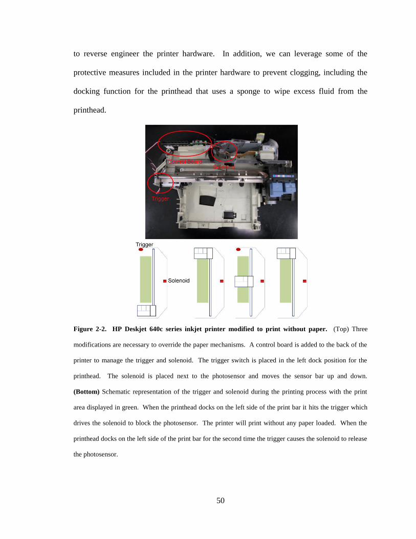
50
to reverse engineer the printer hardware. In addition, we can leverage some of the
protective measures included in the printer hardware to prevent clogging, including the
docking function for the printhead that uses a sponge to wipe excess fluid from the
printhead.
Figure 2-2. HP Deskjet 640c series inkjet printer modified to print without paper. (Top) Three
modifications are necessary to override the paper mechanisms. A control board is added to the back of the
printer to manage the trigger and solenoid. The trigger switch is placed in the left dock position for the
printhead. The solenoid is placed next to the photosensor and moves the sensor bar up and down.
(Bottom) Schematic representation of the trigger and solenoid during the printing process with the print
area displayed in green. When the printhead docks on the left side of the print bar it hits the trigger which
drives the solenoid to block the photosensor. The printer will print without any paper loaded. When the
printhead docks on the left side of the print bar for the second time the trigger causes the solenoid to release
the photosensor.

51
This approach to modifying inkjet printers has advantages and disadvantages.
First, the entire modification can be completed for less than $200. Approximately half of
that expense is for an interface board to properly control the timing between the trigger
switch and solenoid. The .NET Framework and Visual Studio Express Editions can be
downloaded free from Microsoft, eliminating the expense of licensing development
software. Second, we can use the protections built into the printer hardware to prevent
the printer from operating outside of its specifications. Third, the Graphics and Printer
objects allow biological structures to be created programmatically using computer-
assisted models, algorithms, or artificial intelligence (Figure 2-3). Finally, the software
can be built using a range of programming languages from Basic to C++, enabling
researchers to tailor their bioprinting systems to their level of engineering expertise.
Even with these capabilities, this system suffers from the issues related to inkjet
bioprinting and does not provide control over individual channels in the printhead.

52
2.3.4. Issues with Inkjet Bioprinting
Despite the numerous applications of inkjet bioprinting that have been described
in the literature, and the burgeoning field surrounding the technology, there are two major
issues that prevent single-cell inkjet bioprinting from reaching its full potential. The first
issue is the limited mobility of the printhead if no reverse engineering is performed. In
the normal configuration the printhead is limited to 8.5 inches on the X axis and the
length of the printhead on the Y axis. Thus, only biological structures of limited size can
be created with this type of bioprinting system. Second, as noted above, inkjet cartridges
suffer from low throughput. This is mainly due to deposition of salts in the microfluidic
channels during the printing process. This often occurs when evaporation of water from
the bio-ink drop leaves behind solid salts that block the channel orifice. Once the channel
Figure 2-3. Visual C++ code for programmatically creating a series of lines for vasculature
bioprinting. The Printer object contained in the Microsoft .NET Framework provides functions for
interacting with inkjet printers. This object provides a PrintPage that in turn provides a Graphics object for
creating the picture to be printed. In this case the user has provided the total size of the vasculature
(vasculature_size), the space between each blood vessel (vessel_spacing), the length of each blood vessel
(vessel_length), the cell type, and the number of layers to be bioprinted. The FillRectangle() function from
the Graphics object requires four arguments: color, X coordinate, Y coordinate, number of pixels in the X
direction, and number of pixels in the Y direction. Here we use a nested FOR loop to create a line using
one pixel at a time in the Y direction. The COLOR argument for the FillRectangle() function corresponds
to the cell type – for example, cells bioprinted from the red portion of the color cartridge would be
represented by the red (255, 0, 0) color programmatically. More layers can be added by setting the
HasMorePages property to TRUE. This type of programmatic bioprinting can be used to rapidly create
constructs with complex arrangements in each layer.

53
is clogged, it is virtually impossible to restore full functionality to that channel.
Furthermore, cellular debris and other contaminants can clog the microfluidic chambers
as well. As a result, inkjet cartridges typically can only print 400,000 cells per cartridge
before failure (Parzel et al, 2009). This throughput is too low to produce large tissue
constructs. Recently, Parzel et al. experimented with adding a chelating agent (EDTA) to
the bio-ink as an anti-aggregant and they were able to significantly increase the longevity
of inkjet cartridges (Parzel et al, 2009).
2.3.5. Creating a Custom Bioprinting System
One of the best ways to overcome the limitations of desktop inkjet printers is to
develop a specialized bioprinting system. For example, Lee et al. designed a system for
bioprinting fibroblasts and keratinocytes using microvalves instead of inkjet printheads
(Lee et al, 2010) and leveraged this design to bioprint neural structures (Lee et al, 2009).
Another type of system leverages extrusion printing to bioprint cells embedded in
hydrogels. These hydrogels form fused droplets to form biological structures (Moon et
al, 2010). Depending on the type of delivery system these custom designs can have
significantly different throughput and precision than desktop printers.
One of our areas of focus is the bioprinting of skin constructs in situ and high
throughput takes precedence over precise delivery for those applications. Our inkjet
valves sacrifice precision for throughput by delivering approximately 500 cells per drop.
In the context of bioprinting fibroblasts and keratinocytes, this design avoids the pitfalls
associated with single-cell inkjet bioprinting. This system is cartridge-based and allows

54
any cell type or biomaterial that can be packaged into a cartridge to be bioprinted in a
specific location in a wound (Figure 2-4).
2.4. Applications of Bioprinting
One of the main advantages of the cartridge-based delivery system is the ability to
bioprint many different substances by plugging in a new cartridge (Ilkhanizadeh et al,
2007; Pont-Lezica, 2009). Examples of this ability include repairing calvarial defects
using bone morphogenic protein-2 patterned in three dimensions (Cooper et al, 2010) or
directing the fate of stem cells by creating specialized microenvironments with growth
Figure 2-4. Schematic diagram of in situ skin bioprinter. (A) The printhead mounts on XYZ moveable
axes that are mounted to a portable frame. This portable system mounts over the patient bed or operating
table to bioprint skin cells directly in a wound. (B) Magnified view of the scanning system and printhead.
The scanning system scans a wound and creates a map of the wound for the printer to follow. This
printhead is cartridge-based so any material that can be packaged into a cartridge can be bioprinted in
specific locations directly in a wound. The printhead uses inkjet microvalves instead of thermal or
piezoelectric orifices to avoid problems with clogging. In this way the in situ skin bioprinter can bioprint
an exact copy of the skin that the patient is missing.

55
factors (Phillippi et al, 2008). The ability of bioprinting to create spatial patterns was
shown in the development of capillary networks generated from endothelial cells (Cui
and Boland, 2009) as well as the generation of bone constructs from bone marrow
stromal cells (Fedorovich et al, 2008). Drop-on-demand bioprinting allows the creation
of test structures for mechanistic and pharmaceutical testing. For example, a
microprinting system was used to develop liver tissue for metabolism studies (Chang et
al, 2011). We demonstrated that the inkjet printing system can be used for high-
throughput production of single-cell microparticles for high-throughput drug screening or
examining stem cell differentiation (Xu et al, 2008). In this case, the choice of hydrogel
was able to influence the formation of encapsulated cell droplets, resulting in an
inexpensive high-throughput method of producing single cell microparticles.
We have also shown that the properties of the thermal inkjet printhead allow the
bioprinter to act as a high-throughput transfection mechanism for transient transgene
expression (24-48 hours post-transfection; Xu et al, 2009). The inkjet process induces
transient membrane pores that close over the course of several hours (Cui et al, 2010; Xu
et al, 2009). We hypothesized that these pores are introduced through a combination of
the heat flux through the cell and the shear stress induced by pushing a cell through the
output orifice (Figure 2-5). The transient damage to the cell can be leveraged by
combining cells and a plasmid vector in the printhead such that the two components are
bioprinted together. During the bioprinting process, the transient cell damage causes the
plasmid to insert in the cell. Whether inkjet-mediated transfection leads to direct transfer
of DNA into the nucleus (e.g. nucleofection or lentiviral vector transduction: Trompeter
et al., 2003; Naldini et al., 1996) or relies on cell division for transgene nuclear transfer

56
(e.g. basic retroviral vector transduction or cationic liposome delivery: Miller et al., 1990;
Tseng et al., 1999) remains to be determined. In any cases, we have shown that inkjet
transfection is dependent on the size of the plasmid, the concentration of plasmid, and the
type of printhead used (Figure 2-6). The size of the plasmid must be compatible with the
size of the transient pores created in the cell membrane and with an efficient transfer into
the nucleus in order to lead to transgene expression. The transfection efficiency initially
increases with increasing levels of plasmid but further increases in concentration do not
increase the efficiency. Different inkjet printheads also have different transfection
efficiencies due to differences in the output orifices. While the transfection efficiency
was significantly lower than that of electroporation, the cell viability was significantly
higher than electroporation (Figure 2-7). More research is necessary to improve inkjet
bioprinting as a transfection method; however, the power of combining high-throughput
gene manipulation with targeted delivery cannot be understated. Although bioactive
factors can be precisely bioprinted in a construct, these factors will not be continually
produced by the biological construct and will eventually degrade. In contrast, stable
transfected cells are able to continually express bioactive factors to improve construct
development and tissue regeneration. Whether inkjet transfection leads to significant
levels of stable transfectants is not yet known. However, the fact that it provides for
efficient transient transgene expression suggests that, combined with the use of designed
site-specific endonucleases, it could be instrumental in the development of high-
throughput hazard-free protocols for efficient targeted transgene integration (Moehle et
al., 2008) or endogenous gene repair (Urnov et al., 2005), thereby leading to
breakthrough applications both for regenerative medicine (stable expression of integrated
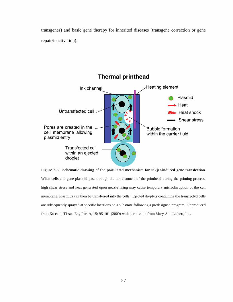
57
transgenes) and basic gene therapy for inherited diseases (transgene correction or gene
repair/inactivation).
Figure 2-5. Schematic drawing of the postulated mechanism for inkjet-induced gene transfection.
When cells and gene plasmid pass through the ink channels of the printhead during the printing process,
high shear stress and heat generated upon nozzle firing may cause temporary microdisruption of the cell
membrane. Plasmids can then be transferred into the cells. Ejected droplets containing the transfected cells
are subsequently sprayed at specific locations on a substrate following a predesigned program. Reproduced
from Xu et al, Tissue Eng Part A, 15: 95-101 (2009) with permission from Mary Ann Liebert, Inc.

58
Figure 2-6. Effects of the printing parameters and conditions on gene transfection. The higher
plasmid concentrations exhibited higher transfection efficiency (a). The use of the HP 29 ink cartridge
caused higher gene expression than the use of the HP 26 ink cartridge which has a larger nozzle size (b).
Compared with the larger plasmid, pIRES-VEGF-GFP, the smaller pmaxGFP plasmid exhibited higher
transfection efficiency of the porcine aortic endothelial (PAE) cells (c). Of note, transgene expression is
measured 24-48 hours post-transfection (transient expression condition). Reproduced from Xu et al, Tissue
Eng Part A, 15: 95-101 (2009) with permission from Mary Ann Liebert, Inc.

59
Figure 2-7. In vitro gene printing. (a) Electrophoreses analysis of printed plasmid DNAs. 1: Size marker;
2: printed pmaxGFP; 3: nonprinted pmaxGFP; 4: printed pIRES-VEGF-GFP; 5: nonprinted pIRES-VEGF-
GFP. The lower plasmid band is the supercoiled form and the upper is the nicked (single-stranded break)
form. (b–e) Morphologies of printed and nonprinted cells. The printed PAE cells exhibited normal
morphology on the collagen gels 2 days after printing (size bar = 5 µm) (b). A number of cells in the
printed samples exhibited strong cytoplasmic green fluorescence (c). The nonprinted cells (controls) also
showed normal morphology (size bar = 5 µm) (d), but were not detectably transfected with the GFP
plasmid (e). (f, g) Viability and transfection efficiency comparison of the inkjet transfection method with
other common gene transfection methods. Compared with the common chemical (Lipofectamine)– or
electroporation (Nucleofection)–associated method, the inkjet transfection method had higher cell viability
after transfection (f). The total transfection efficiency (combined with viability) of the inkjet method is
lower than that of the Nucleofection method but higher than the Lipofectamine method (g). Of note,
transgene expression is measured 24-48 hours post-transfection (transient expression condition).
Reproduced from Xu et al, Tissue Eng Part A, 15: 95-101 (2009) with permission from Mary Ann Liebert,
Inc.

60
2.5. Conclusions
Although great strides have been made in the field of drop-on-demand
biofabrication, much more work is necessary before the major obstacles are overcome.
Most notably, the field is still young and the comprehensive analyses of cell viability and
proliferation in various delivery matrices using different delivery methods have yet to be
performed. In the near future we expect to see biological structures engineered using a
variety of delivery methods tailored to one specific task. We have provided a primer for
researchers seeking to modify desktop inkjet printers for bioprinting purposes. However,
most researchers and commercial enterprises seeking to enter this field would do well to
choose a specific type of biological structure to engineer and customize a bioprinting
machine to those specifications. This field has significant potential and rapid progress in
engineering complex tissues is expected in the next few years.

61
References
Adissu HA, Asem EK, Lelievre SA (2007). Three-dimensional cell culture to model
epithelia in the female reproductive system. Reprod Sci, 14 (8 Suppl): 11-19.
Atala A (2004). Tissue engineering and regenerative medicine: concepts for clinical
application. Rejuvenation Res, 7: 15-31.
Atala A (2009). Engineering organs. Curr Opin Biotechnol, 20: 575-592.
Barron JA, Krizman DB, Ringeisen BR (2005). Laser printing of single cells: statistical
analysis, cell viability, and stress. Ann Biomed Eng, 33: 121-130.
Barron JA, Wu P, Ladouceur HD, Ringeisen BR (2004). Biological laser printing: a novel
technique for creating heterogeneous 3-dimensional cell patterns. Biomed
Microdevices, 6: 139-147.
Binder, K. W., Allen, A. J., Yoo, J. J., & Atala, A. (2011). Drop-on-demand inkjet
bioprinting: a primer. Gene Therapy and Regulation (accepted).
Boland T, Xu T, Damon B, Cui X (2006). Application of inkjet printing to tissue
engineering. Biotechnol J, 1: 910-917.
Bramfeldt H, Sabra G, Centis V, Vermette P (2010). Scaffold Vascularization: A
Challenge for Three-Dimensional Tissue Engineering. Curr Med Chem, 17: 3944-
3967.
Burg T, Cass CA, Groff R, Pepper M, Burg KJ (2010). Building off-the-shelf tissue-
engineered composites. Philos Transact A Math Phys Eng Sci, 368: 1839-1862.
Calvert P (2007). Materials science. Printing cells. Science, 318: 208-209.

62
Chang R, Nam J, Sun W (2008). Effects of dispensing pressure and nozzle diameter on
cell survival from solid freeform fabrication-based direct cell writing. Tissue Eng
Part A, 14: 41-48.
Chang RC, Emami K, Jeevarajan A, Wu H, Sun W (2011). Microprinting of Liver Micro-
organ for Drug Metabolism Study. Methods Mol Biol, 671: 219-238.
Cooper GM, Miller ED, Decesare GE, Usas A, Lensie EL, Bykowski MR, Huard J, Weiss
LE, Losee JE, Campbell PG (2010). Inkjet-based biopatterning of bone
morphogenetic protein-2 to spatially control calvarial bone formation. Tissue Eng
Part A, 16: 1749-1759.
Cui X, Boland T (2009). Human microvasculature fabrication using thermal inkjet printing
technology. Biomaterials, 30: 6221-6227.
Cui X, Dean D, Ruggeri ZM, Boland T (2010). Cell damage evaluation of thermal inkjet
printed Chinese hamster ovary cells. Biotechnol Bioeng, 106: 963-969.
Dash A, Inman W, Hoffmaster K, Sevidal S, Kelly J, Obach RS, Griffith LG, Tannenbaum
SR (2009). Liver tissue engineering in the evaluation of drug safety. Expert Opin
Drug Metab Toxicol, 5: 1159-1174.
Desai N, Alex A, AbdelHafez F, Calabro A, Goldfarb J, Fleischman A, Falcone T (2010).
Three-dimensional in vitro follicle growth: overview of culture models,
biomaterials, design parameters and future directions. Reprod Biol Endocrinol, 8:
119.
Fedorovich NE, Alblas J, de W, Jr., Hennink WE, Verbout AJ, Dhert WJ (2007).
Hydrogels as extracellular matrices for skeletal tissue engineering: state-of-the-art
and novel application in organ printing. Tissue Eng, 13: 1905-1925.

63
Fedorovich NE, de W, Jr., Verbout AJ, Alblas J, Dhert WJ (2008). Three-dimensional
fiber deposition of cell-laden, viable, patterned constructs for bone tissue printing.
Tissue Eng Part A, 14: 127-133.
Guillemot F, Souquet A, Catros S, Guillotin B (2010a). Laser-assisted cell printing:
principle, physical parameters versus cell fate and perspectives in tissue
engineering. Nanomedicine (Lond), 5: 507-515.
Guillemot F, Souquet A, Catros S, Guillotin B, Lopez J, Faucon M, et al. (2010b). High-
throughput laser printing of cells and biomaterials for tissue engineering. Acta
Biomater, 6: 2494-2500.
Ilkhanizadeh S, Teixeira AI, Hermanson O (2007). Inkjet printing of macromolecules on
hydrogels to steer neural stem cell differentiation. Biomaterials, 28: 3936-3943.
Jakab K, Neagu A, Mironov V, Forgacs G (2004a). Organ printing: fiction or science.
Biorheology, 41: 371-375.
Jakab K, Neagu A, Mironov V, Markwald RR, Forgacs G (2004b). Engineering biological
structures of prescribed shape using self-assembling multicellular systems. Proc
Natl Acad Sci USA, 101: 2864-2869.
Klebe RJ (1988). Cytoscribing: A method for micropositioning cells and the construction
of two- and three-dimensional synthetic tissues. Exp Cell Res, 179: 362-373.
Klebe RJ, Thomas CA, Grant GM, Grant A, Gosh P (1994). Cytoscription: Computer
controlled micropositioning of cell adhesion proteins and cells. Methods Cell Sci,
16: 189-192.
Khetani SR, Bhatia SN (2006). Engineering tissues for in vitro applications. Curr Opin
Biotechnol, 17: 524-531.

64
Lee W, Lee V, Polio S, Keegan P, Lee JH, Fischer K, Park JK, Yoo SS (2010). On-
demand three-dimensional freeform fabrication of multi-layered hydrogel scaffold
with fluidic channels. Biotechnol Bioeng, 105: 1178-1186.
Lee W, Pinckney J, Lee V, Lee JH, Fischer K, Polio S, Park JK, Yoo SS.(2009). Three-
dimensional bioprinting of rat embryonic neural cells. Neuroreport, 20: 798-803.
Mikos AG, Herring SW, Ochareon P, Elisseeff J, Lu HH, Kandel R, Schoen FJ, Toner M,
Mooney D, Atala A, Van Dyke ME, Kaplan D, Vunjak-Novakovic G (2006).
Engineering complex tissues. Tissue Eng, 12: 3307-3339.
Miller DG, Adam MA, Miller AD (1990). Gene transfer by retrovirus vectors occurs only
in cells that are actively replicating at the time of infection. Mol Cell Biol., 10:
4239-4242.
Mironov V, Boland T, Trusk T, Forgacs G, Markwald RR (2003). Organ printing:
computer-aided jet-based 3D tissue engineering. Trends Biotechnol, 21: 157-161.
Mironov V, Visconti RP, Kasyanov V, Forgacs G, Drake CJ, Markwald RR (2009). Organ
printing: tissue spheroids as building blocks. Biomaterials, 30: 2164-2174.
Moehle EA, Rock JM, Lee YL, Jouvenot Y, DeKelver RC, Gregory PD, Urnov FD,
Holmes MC (2007). Targeted gene addition into a specified location in the human
genome using designed zinc finger nucleases. Proc Natl Acad Sci U S A, 104:
3055-3060.
Moon S, Hasan SK, Song YS, Xu F, Keles HO, Manzur F, Mikkilineni S, Hong JW,
Nagatomi J, Haeggstrom E, Khademhosseini A, Demirci U (2010). Layer by layer
three-dimensional tissue epitaxy by cell-laden hydrogel droplets. Tissue Eng Part C
Methods, 16: 157-166.

65
Nair K, Gandhi M, Khalil S, Yan KC, Marcolongo M, Barbee K, Sun W (2009).
Characterization of cell viability during bioprinting processes. Biotechnol J, 4:
1168-1177.
Nakamura M, Kobayashi A, Takagi F, Watanabe A, Hiruma Y, Ohuchi K, Iwasaki Y,
Horie M, Morita I, Takatani S (2005). Biocompatible inkjet printing technique for
designed seeding of individual living cells. Tissue Eng, 11: 1658-1666.
Naldini L, Blömer U, Gallay P, Ory D, Mulligan R, Gage FH, Verma IM, Trono D (1996).
In vivo gene delivery and stable transduction of nondividing cells by a lentiviral
vector. Science, 272: 263-267.
Norotte C, Marga FS, Niklason LE, Forgacs G (2009). Scaffold-free vascular tissue
engineering using bioprinting. Biomaterials, 30: 5910-5917.
Parzel CA, Pepper ME, Burg T, Groff RE, Burg KJ (2009). EDTA enhances high-
throughput two-dimensional bioprinting by inhibiting salt scaling and cell
aggregation at the nozzle surface. J Tissue Eng Regen Med, 3: 260-268.
Phillippi JA, Miller E, Weiss L, Huard J, Waggoner A, Campbell P (2008).
Microenvironments engineered by inkjet bioprinting spatially direct adult stem
cells toward muscle- and bone-like subpopulations. Stem Cells, 26: 127-134.
Pont-Lezica RF (2009). Localizing proteins by tissue printing. Methods Mol Biol, 536: 75-
88.
Roth EA, Xu T, Das M, Gregory C, Hickman JJ, Boland T (2004). Inkjet printing for high-
throughput cell patterning. Biomaterials, 25: 3707-3715.

66
Smith CM, Stone AL, Parkhill RL, Stewart RL, Simpkins MW, Kachurin AM, Warren
WL, Williams SK (2004). Three-dimensional bioassembly tool for generating
viable tissue-engineered constructs. Tissue Eng, 10: 1566-1576.
Trompeter HI, Weinhold S, Thiel C, Wernet P, Uhrberg M (2003). Rapid and highly
efficient gene transfer into natural killer cells by nucleofection. J Immunol
Methods, 274: 245-256.
Tseng WC, Haselton FR, Giorgio TD (1999). Mitosis enhances transgene expression of
plasmid delivered by cationic liposomes. Biochim Biophys Acta, 1445: 53-64.
Urnov FD, Miller JC, Lee YL, Beausejour CM, Rock JM, Augustus S, Jamieson AC,
Porteus MH, Gregory PD and Holmes MC (2005). Highly efficient endogenous
human gene correction using designed zinc-finger nucleases. Nature, 435: 646-651.
Wilson WC, Jr., Boland T (2003). Cell and organ printing 1: protein and cell printers. Anat
Rec A Discov Mol Cell Evol Biol, 272: 491-496.
Xu T, Jin J, Gregory C, Hickman J, Boland T (2005). Inkjet printing of viable mammalian
cells. Biomaterials, 26: 93-99.
Xu T, Kincaid H, Atala A, Yoo J (2008). High throughput production of single cell
microparticles using an inkjet printing technology. J Manuf Sci Eng, 130: 021017.
Xu T, Petridou S, Lee EH, Roth EA, Vyavahare NR, Hickman JJ, Boland T (2004).
Construction of high-density bacterial colony arrays and patterns by the ink-jet
method. Biotechnol Bioeng, 85: 29-33.
Xu T, Gregory CA, Molnar P, Cui X, Jalota S, Bhaduri SB, Boland T (2006). Viability and
electrophysiology of neural cell structures generated by the inkjet printing method.
Biomaterials, 27: 3580-3588.

67
Xu T, Rohozinski J, Zhao W, Moorefield EC, Atala A, Yoo JJ (2009). Inkjet-mediated
gene transfection into living cells combined with targeted delivery. Tissue Eng Part
A, 15: 95-101.
Yamada KM, Cukierman E 2007). Modeling tissue morphogenesis and cancer in 3D. Cell,
130: 601-610.
Yeatts A, Fisher JP (2010). Tubular Perfusion System for the Long Term Dynamic Culture
of Human Mesenchymal Stem Cells. Tissue Eng Part C Methods, 2010 Dec 18
[Epub ahead of print].

68
CHAPTER 3
DEVELOPMENT OF A NOVEL DEVICE FOR IN SITU BIOPRINTING OF THE
SKIN
3.1. Design Goals
The ultimate design goal of the skin delivery system is to create a device that not
only bioprints skin cells in situ but also acts as an enabling technology for wound
therapies to reach the clinic. Thus, the first major design goal is to adapt the cartridge-
based design of desktop inkjet printers to the demands of in situ bioprinting. As shown in
Chapter 2, the cartridge design allows inkjet printers to precisely control the spatial
delivery of up to four different cell types at once. Bioprinting normal skin structures in
situ would require dozens of different cell types precisely arranged in three dimensions,
and expansion of each different cell type in vitro for tissue engineering applications
requires different media and supplemental growth factors. Furthermore, a majority of the
wound treatments discussed in Chapter 1 have not been used in tandem to achieve better
clinical outcomes. For example, scarless healing agents may need to be delivered to the
edges of the wound while the center of the wound is covered with a hydrogel that assists
in distribution and proliferation of skin cells. There is no delivery technique currently
available for wound treatment that can combine an arbitrary number of different skin cell
types and wound healing reagents to facilitate better wound healing. Properly designed,
the in situ skin bioprinter can provide this capability using a cartridge-based delivery
system.

69
Bioprinting different materials directly in a wound requires a method of
measuring the dimensions of the wound. We have opted to incorporate a wound
scanning system in the skin bioprinter to rapidly gather the required dimensional data for
bioprinting. A wound scanning system combined with the cartridge-based delivery
system would allow a physician to precisely position virtually any cell, biomaterial, or
adjunctive therapy in the wound bed. Thus, the goal of this aim is to test the core
components of the skin bioprinting system in a preliminary prototype.
3.2. Design Breakdown
The core components of the skin bioprinting system are the movement system, the
cartridge-based delivery system, and the controlling software. The scanning system is
not a core component in the preliminary prototype because the viability of bioprinting
skin cells in situ as a wound therapy must be verified before scaling the skin bioprinter to
a preclinical prototype. Therefore, developing a wound scanning system for in situ skin
bioprinting would not be an efficient use of resources if the bioprinting technique is not
viable.
We established the following design criteria for the preliminary prototype:
1. The system must be portable.
2. The system must be capable of at least 100 µm precision.
3. The delivery system must be cartridge-based and capable of delivering at least
two different cell types.
Each of these design criteria is intended to test a critical component of the preclinical
prototype in a simpler machine. First, portability is crucial to moving the skin bioprinter

70
to the patient for in situ bioprinting. A stationary system would require dedicated space
in the hospital or operating room, limiting the usefulness of the machine as a method of
rapidly treating fragile patients. Second, if the system is to precisely deliver material in a
wound bed it should be capable of moving to a precise location. Human cells typically
have a diameter between 20-30 µm; therefore, the movement system should be able to
move to a location with approximately 100 µm precision. Single-cell delivery techniques
are not viable for this application (Chapter 2, Section 3.3.1.2). As such, the movement
system does not need to be precise to 20-30 µm. Finally, the cartridge-based delivery
system should be capable of delivering at least fibroblasts and keratinocytes from
separate cartridges to test the viability of skin bioprinting as a method for treating skin
wounds.
3.3. Bioprinter v2.0
The skin bioprinter is based on a custom bioprinting system built for in vitro
applications. Bioprinter v1.0 was a position delivery system using stepper motors to
move an inkjet valve to a specific location and place a drop of material. The software for
this system converted a bitmap image into a path for the bioprinter to follow. While
functional, the capabilities of this system were extremely limited mainly due to the sparse
software features. Since the infrastructure for the movement system and delivery system
was already in place, this platform became the test bed for the major components of the
skin delivery system. By improving the software controlling the bioprinter, additional
features became available to improve the capabilities of the bioprinter and test the core
components of the skin delivery system in a murine model.
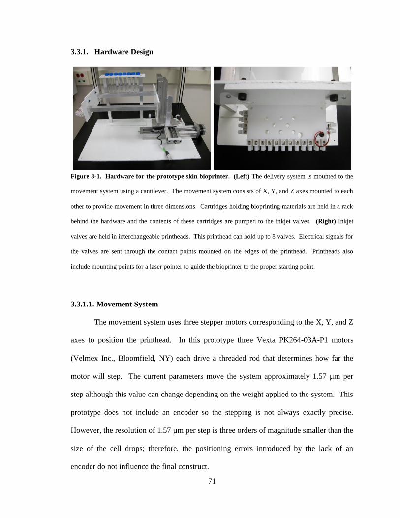
71
3.3.1. Hardware Design
3.3.1.1. Movement System
The movement system uses three stepper motors corresponding to the X, Y, and Z
axes to position the printhead. In this prototype three Vexta PK264-03A-P1 motors
(Velmex Inc., Bloomfield, NY) each drive a threaded rod that determines how far the
motor will step. The current parameters move the system approximately 1.57 µm per
step although this value can change depending on the weight applied to the system. This
prototype does not include an encoder so the stepping is not always exactly precise.
However, the resolution of 1.57 µm per step is three orders of magnitude smaller than the
size of the cell drops; therefore, the positioning errors introduced by the lack of an
encoder do not influence the final construct.
Figure 3-1. Hardware for the prototype skin bioprinter. (Left) The delivery system is mounted to the
movement system using a cantilever. The movement system consists of X, Y, and Z axes mounted to each
other to provide movement in three dimensions. Cartridges holding bioprinting materials are held in a rack
behind the hardware and the contents of these cartridges are pumped to the inkjet valves. (Right) Inkjet
valves are held in interchangeable printheads. This printhead can hold up to 8 valves. Electrical signals for
the valves are sent through the contact points mounted on the edges of the printhead. Printheads also
include mounting points for a laser pointer to guide the bioprinter to the proper starting point.

72
3.3.1.2. Delivery System
The cartridge-based delivery system is similar to that used in traditional inkjet
printing. Each cell type is loaded into an individual cartridge in the same way different
color inks would be contained in different cartridges. However, the printheads in the
novel device use pressure-based inkjet nozzles instead of the thermal or piezoelectric
microfluidic delivery devices used in traditional inkjet printers (Inkjet Valve Model L
MEK, Offshore Solutions Inc., Beaverton, OR). A pressure-based delivery system uses
three components: the pressure source, material reservoirs, and a delivery mechanism.
Air from the pressure source fills the reservoir and drives the material in the reservoir
into the delivery mechanism as it is needed. This method is superior to traditional inkjet
cartridges in the context of in situ printing because it separates the reservoir and delivery
mechanism. An inkjet cartridge marries the reservoir and delivery mechanism in a single
unit. If either the reservoir or delivery mechanism fails, the entire unit fails. Failure of
traditional inkjet cartridges is common in bioprinting due to clogging of the microfluidic
channels (Parzel et al., 2009). Furthermore, traditional inkjet cartridges would need to be
filled and sealed prior to printing. If the cartridge is filled with human cells, then failure
of the cartridge would lead to the loss of all cells contained in that cartridge. Our
pressure-based delivery system solves these issues. The reservoir and delivery
mechanism can be replaced individually should either component fail. Material is only
pumped to the delivery mechanism when it is needed, so failure of the delivery
mechanism does not lead to the loss of all material in the reservoir. In addition,
separation of the reservoir and printhead allows the same printhead to deliver multiple
different cell types or other reagents. The design also provides a method for easy

73
sterilization and maintenance by simply attaching a reservoir of sterilizing fluid or
cleaning fluid to the delivery mechanism (Binder et al., 2011).
3.3.1.3. Hardware Controllers
Control of the movement and delivery systems is comprised of three major tasks:
logic, motor control, and display control. Each of these tasks is encapsulated by a custom
control board. Logic is handled by a MC9S08JM60 (JM60) 8-bit microprocessor
(Freescale Semiconductor, Austin, TX) (Figure 3-2). This microprocessor runs the
software developed in assembly language and deployed using Freescale Codewarrior™.
The logic software converts data sent via USB or RS232 communications into useable
data for the movement controller and delivery system.
Data is sent as a series of 8 bytes representing the control sequence, valves to be
fired, high X register, low X register, high Y register, low Y register, high Z register, and
low Z register. The JM60 processor uses the control sequence to determine which
function to perform. 0x40 (64d) represents a cell drop, directing the controller to use the
X, Y, and Z coordinates to move to a specific location and fire the inkjet valves specified
by the valve byte. The valve byte is a hexadecimal representation of each valve to be
fired. Each valve is assigned one of eight bits for a total of 8 valves that can be used in
this representation. For example, valve 1 would be represented by 00000001b (0x1)
whereas firing valves 2 and 7 would be represented by 01000010b (0x9).
Movement is coordinated by splitting the each of the X, Y, and Z values into two
registers. Since the JM60 is an 8-bit processor, the maximum value for movement that
can be stored in one register is 256. This limitation prevents movement distances of

74
greater than 0.04 cm at one time. To overcome this limitation, the movement values were
split into high and low values for a total of 256*256 possible values. In this way the
motors can move up to 65,536 steps or approximately 10 cm at once. The software in the
JM60 maintains registers that track the current position of the motor. Comparing the
current location to the location provided by the X, Y, and Z values allows the processor
to determine how many steps to move to reach the specified location.
In addition to the functions used for skin bioprinting applications, alternate
control sequences can direct the high and low registers to transmit data for other
functions.

75
The motor controller is connected to the PTD outputs of the JM60 processor
(Figure 3-3). Since the motors are 6 wire bipolar steppers, each motor has four coil
drivers and two center taps connected to the 24 volt power supply. Once the JM60
calculates how many steps to move, it uses a clock signal to pulse the coils and drive the
motor. The microprocessor also determines the direction of movement and uses this
signal to drive the stepper motors forward or backward.
Figure 3-2. Schematic diagram of MC9S08JM60 microprocessor for bioprinting applications. The
processor and power components shown on the left drive the processing capabilities of the board. BDM
support allows a computer to connect directly to the microprocessor for debugging routines and to change
the programming of the board. USB and RS232 communications to the controlling computer connect to
the logic board. This board handles the data logic by parsing data passed by the computer into X, Y, and Z
coordinates and the inkjet valve to fire. PTA communicates with the decoder for the push buttons for
manual control of the motors and valves. PTC communicates with the LCD display to show status
information to the user. PTD communicates with the drivers for the motors. PTF communicates with the
drivers for the solenoid valves. PTG communicates with the switch decoder for the push buttons.

76
The display and control driver maintains the LCD display and decodes the manual
control buttons on the device controller (Figure 3-4). The PTA, PTC, PTF, and PTG
outputs from the JM60 processor output data to the display and determine the code to
operate when a valve is fired. The driver also allows the user to manually move the X, Y,
and Z axes instead of using software to create a motion profile.
Figure 3-3. Schematic diagram of the motor controllers for bioprinting applications. Each of the four
controllers connects to the PTD outputs of the JM60 microprocessor. This unit is capable of driving X, Y,
and Z motors as well as an additional motor to rotate the printhead for curved surfaces. The
microprocessor uses the clock signal to pulse the coils of the motors and step the motor shaft. A separate
signal determines if the motor steps clockwise or counterclockwise. These motors are driven by the 24 volt
power supply.

77
3.3.2. Software Design
Bioprinter v2.0 was designed as a test for the core software components of the
skin delivery system and as an all-purpose bioprinting machine for both in vitro and in
vivo applications. The software is event-based object-oriented C++ programming based
on the .NET Framework 2.0 (Microsoft Corporation, Redmond, WA). Object-oriented
programming separates different functions into different independent modules to ensure
that each major component can be altered without affecting the rest of the software.
Event-driven architecture uses event emitters to trigger changes in the program state
which are caught by event handlers. The overall architecture is a three-tier design with
each of the three major areas of communication separated into different modules (Figure
3-5). The Interface component handles all communications with the user. The Logic
component handles all communications among software components. The Database
component handles all communications between the software and the file system. All
other program components and communications are based on this main design.
The goal of this software architecture is to become the base for the preclinical
skin bioprinting prototype. Communications among the software components is designed
to use generic C++ objects such as strings and arrays. Although custom communications
objects would provide better communications for this specific application, Bioprinter
Figure 3-4. Schematic diagram of the display and control driver for bioprinting applications. This
custom driver connects to the PTA, PTC, PTF, and PTG outputs from the JM60 processor. PTA and PTG
connect to the decoder for the push buttons on the control panel. These buttons control X, Y, and Z
movement as well as providing the ability to reverse the movement of each axis. The valve open time and
atomizer spray time can also be controlled by the push buttons. PTC displays information to the user
including the valve open time, atomizer spray time, and which valve is currently firing. PTF drives the
solenoid valves using inductors.

78
v2.0 must provide methods for replacing every component in preparation for the
preclinical prototype. Therefore, using generic C++ objects for communications will
remove a layer of software implementation for the preclinical prototype. The final
prototype will use custom communications once the concepts of the skin delivery system
have been validated in preclinical experiments.
The three main components of the architecture are created and linked in the
main() function of the Bioprinter program (p. 173). As a result, resources for the
Interface, Logic, and Database components are constructed and maintained outside of any
other object. These resources are released only when all other routines exit and main()
Figure 3-5. Schematic representation of three-tier architecture for Bioprinter v2.0. Arrows indicate
direction of communication. The Interface component communicates with the user and relays information
to the Logic component. No other component can interact with the user and every component that needs to
send information to the user must do so through the communication in the Logic component. All
communication among the software components is handled by the Logic component. The Database
component handles all communication with the file system. The Printer Controller component
encapsulates the Printer component that handles communications with the bioprinting hardware. By
encapsulating the Printer component in the Printer Controller, the Printer communications can change
without affecting the Logic component. This initial design tests the core components of the skin delivery
system.
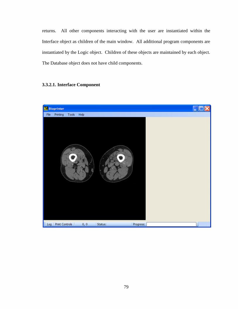
79
returns. All other components interacting with the user are instantiated within the
Interface object as children of the main window. All additional program components are
instantiated by the Logic object. Children of these objects are maintained by each object.
The Database object does not have child components.
3.3.2.1. Interface Component

80
Bioprinter v2.0 is backwards compatible with programs created using Bioprinter
v1.0. This design decision was made to validate the v2.0 software by creating the same
bioprinted structures made with v1.0. Since the v1.0 software parses bitmaps to
determine the bioprinting path, this functionality became the initial core of the Bioprinter
v2.0 program. This core was later expanded to include additional functions for general
purpose bioprinting.
Bioprinter v2.0 begins operation by running the Interface_Load routine (p. 175)
on the main form of the program. This routine prepares the rest of the program for proper
operation. The function searches for the default configuration listed in the file directory
under "Default Configuration.biocfg". Other configurations can be loaded by the user
manually after the software has finished loading the default configuration.
Figure 3-6. Main window of Bioprinter v2.0 with MRI image displayed. (Top) Four tasks are
available from the toolbar. File contains two commands: Open Image and Exit. Printing contains five
commands relating to the bioprinting process: Define Grid, Parse Image, Print Controls, Print, and
Automatic Printing. Tools contains seven commands for configurations: Set Port, Set Printer, Define
Edges, Set Scaling Factor, Clear Image, Motor Controls, and Bioprinter Configuration. Help contains the
About command which displays copyright information about this program. (Middle) The image work area
of the Bioprinter v2.0 program displaying a MRI slice of lower extremities. The location of the cursor
within this image is displayed as X, Y coordinates in the toolbar at the bottom of the window. (Bottom)
Tasks are available for bioprinting structures without using images. Log relays information from the
bioprinter to the user, keeping a record of all messages, errors, start times, pause times, and stop times.
Print Controls provides commands for rapidly bioprinting structures. Mouse cursor coordinates are
displayed along with the current status of the bioprinter. The Status label and Progress bar allow the user
to quickly determine the status of the bioprinter without needing to look in the Log.

81
Configurations are loaded by passing a System::Collections::ArrayList through the Logic
object and into the Database object for communication with the file system. The default
configuration includes the following items for each of the four possible motors in the
motor driver:
1. Axis
2. Zero Position
3. Minimum Position
4. Maximum Position
5. Maximum Velocity
6. Maximum Acceleration
These values function as bounds for the possible movements of the bioprinter and prevent
the bioprinting system from operating beyond its hardware limitations.
Images are loaded using the File->Open Image command. A variety of image
types can be loaded including bitmaps, Joint Photographic Experts Group (JPEG) images,
Graphics Interchange Format (GIF) images, Tagged Image File (TIF) images, and
Portable Network Graphics (PNG) images. The image is displayed as the background
image in the PictureBox that makes up the main window of the program interface. The
image is held in memory as the bitmap representation of the image regardless of the types
of image that is currently opened. This representation is required in the .NET 2.0
Framework because functions for parsing the pixel data in the System::Drawing
namespace are only available to bitmap images. In addition, the Interface component
allows the user to use multiple images to create a three-dimensional structure consisting
of varied two-dimensional layers. Each time a new image is opened the Interface

82
component will add a new layer to the bioprinted structure if the user requires additional
layers. Images are then parsed using the Printing->Parse Image selection.
Parsing an image uses the data format for Bioprinter v1.0 to maintain backward
compatibility (p. 179). However, additional features were added to improve the parsing
and add functions beyond what was available in the original software. First, the software
prompts the user to define the image dimensions in centimeters by providing the number
of image pixels that correspond to a certain number of centimeters. This conversion
allows the software to match the real dimensions of the image without requiring the user
to create images with thousands of individual pixels corresponding to single drops of
cells. In addition, the user can define the spacing between drops to create structures with
arbitrary resolutions. However, bitmap processing only uses integers in the .NET 2.0
Framework. Therefore, the drop spacing is converted from a double precision floating
point number provided by the user to an integer by multiplying the floating point drop
spacing by the number of pixels in one centimeter. This floating point arithmetic is
rounded to the next highest integer using the System::Math::Ceiling() function. The
Parse Image function then iterates through each pixel in the image to determine if it will
be part of the bioprinting path. This action is performed using a nested for loop to
evaluate pixels in each row and column. Iterations of the for loops are performed using
the drop spacing integer to skip any pixels that will not be part of the bioprinting path.
Each valid pixel is evaluated by checking to see if the pixel is black. In the Bioprinter
v1.0 software, black pixels indicated empty space. This relationship holds true for the
Bioprinter v2.0 software. If the pixel is not black, its X and Y values are added to a
System::Collections::ArrayList of valid points along with the sum of the red, green, and

83
blue values of the pixel in the format (X,Y)@0#SUM(Red,Green,Blue), where @ and #
are data spacers and 0 represents the size of a particular cell drop. This format allows the
user to define up to 762 possible cell types for bioprinting. The final pixels are sent to
the Logic component for further processing.
Although the Parse Image function can determine bioprinting paths for virtually
any image, large images are slow to process and the resulting paths are complicated. The
Printing->Define Grid function was added to reduce the time needed to parse these types
of images (p. 204). With this routine the user can break the image into discrete pieces of
arbitrary length and width (Figure 3-7). Grid information is provided by the child form
that determines the grid length and width from the user. Once this information is stored
in the program it becomes part of the Paint event that is fired when the main window
must be redrawn.
Figure 3-7. Main window of Bioprinter v2.0 with grid displayed over MRI image. The user defined a
16x16 pixel grid for the entire image. Each portion of the grid represents a separate bioprinting path.
Empty grids containing only black pixels are ignored during image parsing. This enhancement
significantly improves the time needed to parse an image.

84
After the image is parsed, each grid will become a separate bioprinting path. This
case is handled by the Parse Image function by using the same bitmap pixel examination
for an image with no grid. However, the pixels are now bounded by the edges of the
grid. Since each section of the grid corresponds to a separate bioprinting path, the time
needed to find the optimal bioprinting path is reduced by an amount proportional to the
number of grids. Although this algorithm significantly reduces the time needed to parse
an image and determine the optimal bioprinting path, it still parses significant amounts of
black pixels that contain no data, reducing its effectiveness in parsing large images.
To avoid parsing large amounts of pixels with no data, the Tools->Define Edges
function was added to the main form (p. 207). This algorithm uses the Image Processing
Lab software available under the GNU General Public License (Krillov, 2010) to
calculate the edges of an image. These edges are stored as an additional Bitmap in the
Interface object as an edge map (Figure 3-8).
Figure 3-8. Main window of Bioprinter v2.0 with edges of MRI image displayed. The Image
Processing Lab software is capable of detecting edges for nearly every anatomical feature in the MRI
image. These edges are used in the Bioprinter edge defining algorithm to determine the outer edges of the
displayed image to parse the image without examining the black pixels with no data.

85
Since the edge map has the same dimensions as the original image, the edges can
be overlaid on the original image and maintained in the Paint event in the same way that
the grid is redrawn as needed. In the Parse Image function, the algorithm only uses the
outer edges of the edge map. This is necessary because the purpose of the algorithm is to
exclude the black pixels outside of the image and not exclude information within the
image (Figure 3-9).
The edge map is used in the Parse Image algorithm to parse pixels only within the
outer edges. However, the outer edges are defined by lines that span more than one pixel.
Thus, the parsing algorithm traverses the edge map by row until it locates the innermost
Figure 3-9. Main window of Bioprinter v2.0 with outer edges of MRI image defined in memory. The
algorithm for determining the outer edges of an image successfully identifies the outer edge with over 95%
accuracy. Pixels incorrectly defined as outer edges are ignored in the parsing algorithm. This edge map
allows the software to ignore the large amount of empty space surrounding the areas of interest in the
image.

86
edge pixels of each row and uses the pixel information between those two edges as the
area to parse.
The final case of the Parse Image algorithm combines edges and grids to create
the most efficient algorithm for parsing bioprinting paths. In this case, only the area
inside the edges is gridded so each grid within the edges will be a separate bioprinting
path (Figure 3-10). This case for the parsing algorithm is a combination of the edge and
grid algorithms, bounding the examined pixels by both the defined edges and the grid.
Figure 3-10. Main window of Bioprinter v2.0 with MRI image overlaid with both edges and 16x16
pixel grid. The Define Grid function can operate within the edges defined by the edge map. The
combination of algorithms allows the Parse Image function to separate the bioprinting paths within the
edges for maximum efficiency in parsing. The bottom and right edges of the image are bounded by the
grid to provide a defined limit to the parsing algorithm.

87
Once the image has been parsed and the pixel data converted into a format
conducive to bioprinting, the data can be sent to the Logic object using the Printing-
>Print command. This command allows the user to define an offset to the X and Y data
which will move the beginning of the bioprinting path to a location defined by the user.
This offset allows the user to add a calibration device such as a laser pointer to ensure
that the bioprinter begins printing the image at a precisely repeatable location.
Together, these image parsing algorithms in Bioprinter v2.0 form the core
components of the imaging algorithms for the skin bioprinting system. The design goals
for the skin bioprinting system state that the system should be able to tailor therapy for
each individual wound. The image parsing algorithms provide a method of testing the
ability of the software to generate bioprinting paths for virtually any type of image.
Thus, testing and validation of the image parsing algorithms can be performed in a model
of the skin bioprinting system without requiring that the final system be assembled. In
addition to validation for the skin bioprinting system, this portion of the Interface object
can be used for general bioprinting purposes.
While image data is useful for applications where the bioprinter must follow a
defined path, creating images, edges, and grids for large structures can be time-
consuming. Some bioprinting applications, including skin bioprinting if the imaging
system is offline, do not require imaging techniques to operate. To provide greater
functionality to Bioprinter v2.0, the Print Controls button was added to the Interface (p.
220). The Print Controls button provides some functions that are available in the
Printing menu as well as allowing the user to perform various bioprinting tasks (Figure 3-

88
11). By placing these functions in an easily accessible menu the bioprinting interface can
be used to quickly create complex structures.
Figure 3-11. Main window of Bioprinter v2.0 with Print Controls menu displayed. Functions
available in the Printing menu are available on the left of the Print Controls menu. These buttons allow the
user to pause, resume, and stop the bioprinting process at any point during the experiment. Flush Line
causes the valve listed in the box to fire as long as the button is held. Set Dwell Time allows the user to
define the open time for the valves in software rather than needing push buttons on the hardware. Available
Commands lists the actions provided to the user: Print, Electrospin, Move, Sterilize, Flush Line, and
Live/Dead Assay. Each action requires specific parameters entered using the text boxes on the right. The
Do Command button sends the selected command and the user's parameters to the Logic object.

89
The Print Controls menu lists six actions available to the user:
1. Print
2. Electrospin
3. Move
4. Sterilize
5. Flush Line
6. Live/Dead Assay
These commands are held in a ListBox object. New commands can be easily added to
the Interface component by adding them to the end of the ListBox. The commands are
interpreted by the Printer Controller object; therefore, the Interface object only needs to
combine the command and its parameters in a way that can be easily parsed by the Printer
Controller. Each command requires a set of parameters that are provided by the text
boxes in the Print Controls menu. These parameters are provided to the Logic object by
the Do Command button (p. 220). Print creates a rectangle for rapid bioprinting without
using images to create layers. It requires that the user enter the X and Y dimensions of
the rectangle, the spacing between bioprinted drops, and the valve number to use.
Electrospin operates the additional electrospinning apparatus that can be used to improve
the mechanical properties of bioprinted constructs by adding electrospun polymers. This
apparatus is not used for skin bioprinting; therefore, the nuances of the electrospinning
system will not be discussed in detail in this work. Move uses the X, Y, and Z values
provided by the user to move the bioprinter to a specific point. Sterilize does not require
inputs from the user. As a standalone command, Sterilize is operated by the Printer
Controller object. Flush Line is an additional method of clearing the valve feed lines and

90
requires that the user define the valve number to be flushed. Live/Dead Assay is a
standalone command that is operated by the Printer Controller object. These commands
are discussed in further detail in section 3.4.2.5.
Since these commands are available in a ListBox object, they can also be used as
a method of generating complex constructs automatically (Figure 3-12).
Figure 3-12. Automatic printing menu of Bioprinter v2.0. (Left) Main display of the automatic
printing menu with a printing program loaded. Printing programs can be saved and loaded at any time and
their contents will be loaded into the ListBox at the bottom. Automatic printing programs are given an
experiment title and an author name displayed at the top of the screen. The Available Commands are
identical to the Print Controls menu on the main Bioprinter v2.0 window. (Right) Main display of the
automatic printing menu with an available command selected. Each parameter for the available commands
is set to appear and disappear as the user selects different commands. In this case, the user has selected to
print a rectangle. This selection brings up a height and width for the rectangle along with the drop spacing
and valve, similar to the Print command from the Print Controls menu.

91
Automatic printing enables the user to create complex constructs without constant
user input. It provides a method of testing the ease of use of the bioprinting system. Ease
of use is the purpose of the Interface component for Bioprinter v2.0 such that the
software can be modified with user input to form the Interface component for the skin
delivery system.
3.3.2.2. Logic Component
The Logic component acts as the communications controller for all other program
components. Its main functions are to instantiate resources for objects that do not interact
directly with the user, maintain proper thread control, and properly release resources for
all child objects when necessary. Bioprinter v2.0 operates on two separate threads with
the main thread running the interface and the secondary thread operating the bioprinter
hardware. Since the Logic object controls communication and threading it must ensure
that communications are presented to the proper thread to avoid resource conflicts. This
requires that all communications to the Interface object must be checked with an Invoke()
call to the interface thread. In this way the Logic object ensures that communications are
routed correctly to the proper threads. This method of communication only applies to
functions relaying information to the user. Most of the Logic functions merely pass
information to the proper objects. Pixel information from the image parsing algorithms is
passed to the Organ object, commands from the Print Controls and Automatic Printing
menus are passed to the Plotter Handler object, and filenames and data arrays are passed
to the Database object.

92
Instantiation of child objects is handled in the Logic constructor. When the main
program creates a Logic object, the resources for the child objects are automatically
allocated. This ensures that null reference exceptions do not occur except in rare
occasions. The Logic destructor releases these resources upon exiting the program. This
method of allocation and destruction prevents the software from attempting to access
resources that are not available and ensures that those resources are released at the proper
time.
The hardware thread that runs the Plotter Handler object is tightly controlled by
the Logic object. Thread handles are valuable system resources that are difficult to
recover if improperly allocated. The handle to the hardware thread is created only when
the bioprinting process needs to start, using a ParameterizedThreadStart delegate to pass
either the pixel data from the image parsing algorithm or commands from the Print
Controls and Automatic Printing menus. Crucially, the Logic object copies data from the
interface thread into new allocated memory before passing the data to the hardware
thread. This memory allocation prevents the hardware thread from accessing data on the
interface thread.
3.3.2.3. Database Component
The Database component is similar to the Logic component in that it only
performs a specific function. Database is responsible only for communications with the
file system. It only communicates with the Logic object to relay information to the user.
In the communications process the Database object does not require knowledge of the
contents it reads or writes to the file system. Instead, it uses a FileInfo object combined

93
with a StreamWriter to read or write the contents of generic
System::Collections::ArrayList objects. This method of interacting with the program and
the file system allows the contents of the ArrayLists to change without affecting the
functions in the Database object.
3.3.2.4. Organ, Organ Layer, and Grid Components
Data from the image parsing algorithm is stored by the Logic object in a child
object called Organ (p. 244). The Organ object is a representation in memory of the
three-dimensional structure defined by the user with the image parsing algorithm (Figure
3-13).
Figure 3-13. Schematic representation of the Organ object. An Organ object consists of a
System::Collections::ArrayList of Organ Layers corresponding to the image layers defined by the user in
the Interface component. Each Organ Layer in turn consists of an ArrayList of Grid objects corresponding
to the grids defined by the user in the interface. Each Grid object holds the pixel data for that grid arranged
as a directed graph. The Grid objects hold the X and Y data for the bioprinted structure while the Organ
Layer objects correspond to the Z axis.

94
Organ maintains knowledge of the Z axis for the bioprinted structure, exposing
methods for adding and deleting layers of the structure. In addition, Organ can direct any
OrganLayer to calculate the bioprinting path. This functionality enables the user to
bioprint the path for any layer or all layers at once. The Logic object only communicates
with the Organ object – it does not know that an Organ consists of OrganLayers.
Likewise, the Organ object does not know that an OrganLayer consists of Graph objects.
This separation of communications allows the implementation of the data objects to
change without affecting the rest of the software.
The OrganLayer object maintains a System::Collections::ArrayList of size equal
to the number of rows of grids in the image parsing algorithm (p. 244). Each ArrayList
row holds an ArrayList of size equal to the number of columns of grids in the image
parsing algorithm. This two-dimensional array represents the X and Y data for each Z
layer of the bioprinted structure. Thus, the bioprinting path for any grid can be calculated
with a function that takes as parameters the row and column numbers of that grid. In
addition, the bioprinting path for any grid can be calculated independently of one another.
OrganLayer is responsible for interpreting the data provided by image parsing algorithm
and converting it to X, Y, Cell Size, and Cell Type data for the Graph object.
OrganLayer does have knowledge of the implementation of the Graph object.
The Graph object represents the data from the image parsing algorithm as an
undirected graph (p. 255). The vertices (V) and edges (E) represent the pixel data and the
drop spacing, respectively. This undirected graph is not necessarily dense [|E| = O(|V|2)];
therefore, an adjacency list is the preferred method of representing the graph in memory
(Weiss, 2004a). The space requirement is O(|E| + |V|) instead of O(|V|2). For large

95
images with vertex numbers approaching 100,000 or more points an exponential space
requirement would quickly overwhelm the available memory. The adjacency list ensures
that the graph size is approximately linear with the number of vertices.
Graph implements a number of methods for finding and manipulating data. To
optimize searching through a large amount of data, each vertex is sorted by the X
coordinate first and then Y if the X coordinates between two points are identical. This
implementation provides O(V) performance for additions and O(log V) performance for
find operations and deletions (Weiss, 2004b). Deletions achieve logarithmic performance
by using the find algorithm to locate the node to delete.
Graph calculates a bioprinting path from the vertices using a variant of Dijkstra's
algorithm for undirected graphs. This is a greedy algorithm that chooses the shortest
distance to the next vertex at each evaluation, taking into account the cost of switching to
a different valve. The time performance of this algorithm is O(|V|). Briefly, at each point
the algorithm examines the cost of moving to each of the points in the adjacency list. The
lowest cost move becomes the next point and the first point is marked as already checked.
The marking operation is O(log V) time because it uses the find operation to locate the
proper vertex. The lowest cost point is first determined by comparing the cost to a
System::Double::MaxValue number representing the highest value that can be stored in a
32 bit computer. This ensures that the first comparison is always valid and will always
provide a path for the bioprinter to follow. This algorithm does not always find the
optimal shortest path through the graph but is guaranteed to find a path that traverses all
vertices. If the algorithm reaches a vertex with no vertices in the adjacency list it restarts

96
from the first unvisited node. In this way the algorithm can ensure that there will always
be a path for the bioprinter.
3.3.2.5. Plotter Handler
The Plotter Handler component implements the Printer Controller component
listed in the architecture schematic (Figure 3-5). It is listed as a plotter instead of a
printer because the implementation controls more than the bioprinter. The purpose of the
Plotter Handler object is to act as a communications barrier between the bioprinter and
the rest of the software. This encapsulation allows the direct interface to the bioprinter to
change without affecting the rest of the software. The communications barrier is crucial
to the design of the project – it alone enables Bioprinter v2.0 to become the foundation of
the clinical skin delivery system.
Plotter Handler creates the resources for the bioprinter and maintains all
communications with the bioprinter interface. No other component can directly interact
with the bioprinter and the bioprinter must send communications through Plotter Handler
to reach the Logic component. In addition, Plotter Handler parses the commands sent
from the Logic object into data that can be used by the bioprinter interface. After the user
has parsed an image, the Logic object directs the Organ object to create a bioprinting path
using the Organ Layer and Grid components. This path is sent to Plotter Handler in a
separate thread. Plotter Handler draws out the X, Y, and Z coordinates as well as the cell
type from this data and sends it to the bioprinter one point at a time. By sending the
points individually Plotter Handler provides program hooks to pause and stop the

97
printing process. These commands are available under the Print Controls menu in the
Interface component.
Plotter Handler also interprets the commands for automatic printing. Each
command is contained within its own subroutine. The master routine for automatic
printing is the Automatic Printing function that is exposed to the Logic object. This
function takes as its parameter the list of commands from the Interface menu. Plotter
Handler iterates through this list and calls its private subroutines to perform each task.
The commands have their own parameters that are required and will communicate to the
user if additional inputs are needed (p. 282). In addition, Plotter Handler can create its
own set of points for the bioprinter to follow (p. 292). This function operates when the
user bypasses the image parsing algorithm and uses the Print Controls menu to create a
bioprinted structure. This ability ensures that the software does not solely rely on the
Organ object to function correctly.
3.3.2.6. Plotter
Although it interacts with the bioprinting hardware, Plotter is the simplest
component of Bioprinter v2.0. It handles all direct communications with the bioprinter
and relays information to Plotter Handler. Plotter uses a System::IO::SerialPort to
communicate with the bioprinter at 9600 baud. All resources for the SerialPort are
maintained by the Plotter object in the constructor and destructor. This includes closing
the port upon destruction of the Plotter object; otherwise, no other software would be
able to access that port.

98
The most important function in the Plotter object is the Write command. Write
takes four integers as parameters. These integers have different meanings depending on
the command but Plotter has no knowledge of the different meanings. For example, the
operational code for printing sends the X, Y, and Z coordinates as well as the cell type
whereas the operational code for electrospinning sends the voltage and flow rate. These
commands are interpreted by the bioprinter hardware but use the same function in Plotter
to send the information to the bioprinter. The four integers are converted into
hexadecimal digits and divided into the high and low bytes for a total of 8 bytes sent to
the bioprinter. Once these bytes have been placed in an array they are written into the
SerialPort buffer for the bioprinting hardware. Plotter then uses a
System::Threading::EventWaitHandle to block the bioprinting thread until the hardware
signals completion of the cell drop, indicated by receiving the # sign as hexadecimal
0x23. The EventWaitHandle prevents Plotter Handler from sending additional
commands before the bioprinter has completed the assigned task.
3.4. Validation of Preliminary Prototype
Validation of the preliminary prototype was performed by ensuring that the
cartridge-based delivery system could provide accurate deposition of materials. A series
of bitmap images were created, representing cell drops at 1, 2, 5, and 10 mm apart. Laser
pointers were mounted in place of the inkjet valves and the distances between movements
were marked and measured with a digital micrometer. In each case the movement system
was able to precisely move to within 100 µm of the intended destination. These
measurements lose precision due to errors introduced in marking the laser pointer.

99
However, this validation demonstrated that the movement system operates in accordance
with the design goals. Validation of the inkjet valves was performed in conjunction with
the in situ skin bioprinting experiment discussed in Chapter 4.
3.5. Summary of Preliminary Prototype
The goal of this aim was to create a prototype skin bioprinter that could act as a
test bed for the core components of an in situ bioprinting system. To that end, we
developed a movement system capable of 1.57 µm precision, a cartridge-based delivery
system capable of delivering up to 8 different cell types, and software capable of
coordinating the hardware components. This prototype was validated in a murine wound
model (Chapter 4) and subsequently became the basis for a preclinical skin bioprinter
prototype (Chapter 5).

100
References
Binder, K. W., Zhao, W., Dice, D., Tan, J., Kang, H. W., Atala, A., & Yoo, J. J. (2011).
Development of an in situ skin bioprinter for extensive burn wounds. Nat
Biotechnol.(Submitted).
Krillov, A. (2010). Image Processing Lab. http://code.google.com/p/iplab/ [On-line].
Parzel, C. A., Pepper, M. E., Burg, T., Groff, R. E., & Burg, K. J. (2009). EDTA
enhances high-throughput two-dimensional bioprinting by inhibiting salt scaling
and cell aggregation at the nozzle surface. J Tissue Eng Regen.Med., 3, 260-268.
Weiss, M. A. (2004a). Graph Algorithms. In Data Structures & Algorithm Analysis in
C++ (pp. 327-389).
Weiss, M. A. (2004b). Trees. In Data Structures and Algorithm Analysis in C++ (pp.
121-179).

101
CHAPTER 4
IN SITU BIOPRINTING OF THE SKIN IN A MURINE MODEL
4.1. Disclaimer
Text of this chapter is reproduced from Binder et al., 2011.
4.2. Introduction
Using the prototype developed in Chapter 3, the feasibility of using the skin
delivery system to repair wounds was evaluated in a murine model. Although this animal
model is not identical to human skin, it is a low-cost model that will establish the concept
of the skin delivery system. In this experiment we bioprinted skin constructs of
fibroblasts and keratinocytes to repair skin wounds. During this process two major
aspects of the delivery system were tested. First, the ability of the skin delivery system to
control delivery of two different cell types was examined. This testing was performed to
validate the movement system, cartridge-based valve delivery system, and controlling
software for in situ bioprinting applications.
The second major aspect of the delivery system that was tested was the use of a
fibrin/type I collagen delivery matrix to act as scaffolding for the printed cells. As
described in Chapter 2, bioprinting macro-scale constructs currently requires scaffolding
to hold the printed cells in place. In this application cells were mixed with fibrinogen and
collagen and an equal amount of thrombin was bioprinted to convert the fibrinogen into
fibrin. We selected a fibrin/collagen matrix for three reasons. First, the

102
fibrinogen/collagen mixture is liquid and has a viscosity similar to water. Inkjet valves
must print a material similar to water to avoid malformed droplets. Although the initial
mixture is similar to water, addition of thrombin converts the liquid to a gel which will
serve as scaffolding. Second, fibrin and collagen both play important roles in normal
wound healing and therefore should assist the normal healing response. Third, fibrin and
type I collagen have already been used to create skin constructs and their properties are
well defined for this application (Grant et al., 2002; Otto et al., 1995).
In addition to testing these major aspects of the delivery system, the in vivo data
answered important questions about bioprinted skin constructs including:
1. Viability of printed skin cells.
2. Ability of printed layers to withstand the weight of additional printed
layers.
3. Ability of printed constructs to adhere to a wound bed.
4. Ability of printed constructs to withstand the bandaging process, including
bandage changes.
5. Time required for formation of skin tissue.
4.3. Methods
4.3.1. Cell Culture
All animal procedures were performed according to the protocols approved by the
Wake Forest University Health Sciences Animal Care and Use Committee. Human
fibroblasts used in the study were obtained from human foreskin and cultured in high
glucose Dulbecco’s modified Eagle’s medium (Gibco-BRL, Grand Island, NY) with 5%

103
fetal bovine serum and 1% antibiotic solution. Human keratinocytes were obtained from
ScienCell (Carlsbad, CA) and cultured in keratinocyte serum-free media (Gibco-BRL)
with 1% antibiotic solution. When sufficient cell numbers were reached in culture, cells
were trypsinized for 5 min and suspended in the printing solution, which was composed
of a mixture of 25 mg/mL fibrinogen and 1.1 mg/mL type I collagen in phosphate-
buffered saline.
4.3.2. Cell Viability
The viability of fibroblasts and keratinocytes after printing was evaluated by a
two-color fluorescence live/dead assay. Fibroblasts and keratinocytes were printed
separately in a 1 cm x 1 cm construct in a 6-well plate, 3 wells per cell type. Cell drops
were delivered at 2 mm intervals for a total of 25 drops per well. Viability was examined
at 10 minutes and 24 hours post-printing by adding 2 ml of viability testing solution (2
μM calcein AM and 4 μM ethidium homodimer (EthD-1; Molecular Probes, OR) in 10
ml Phosphate Buffered Saline (PBS)) to each sample. The samples were incubated for 30
min at 37°C followed by a rinse with PBS. Each of the 3 samples was viewed using a
fluorescent microscope at 100x magnification. Viability was calculated by examining 3
representative pictures per well with a minimum of 50 cells per field of view for a total of
9 samples examined per cell type. The number of live cells stained with calcein AM
(green) was counted and this number was compared to the total number of cells. This
experiment was also used to estimate the number of cells per inkjet drop. Immediately
after printing the number of viable cells in each sample was viewed under brightfield

104
microscopy. The total number of cells in each well was counted and divided by the total
number of cell drops.
4.3.3. Animal Model and Testing
The skin delivery system prototype was evaluated by creating a 3 x 2.5 cm (L x
W) full-thickness excisional skin defect on the dorsa of 36 female outbred athymic nude
(Nu/nu) mice (Charles River Laboratories, Raleigh, NC). This defect represents a wound
of approximately 50% TBSA. Mice were split into three groups of 12 animals. One
group received no treatment for the wounds, the second received fibrin and collagen
alone (matrix-only), and the final group was treated with a printed layer of human
fibroblasts followed by a printed layer of human keratinocytes. One layer of fibroblasts
(passage 8-12) was printed at 1 mm drop intervals, and this was followed by printing of
an equal amount of 20 IU/mL thrombin. The thrombin was allowed to react for 15
minutes before a layer of keratinocytes (passage 6-10) was printed, and this was again
followed by thrombin. Matrix-only mice received the same amount of fibrinogen
combined with collagen instead of cells, and this mixture was printed to form a dual layer
construct. Thrombin was printed onto each layer and allowed to react for 15 minutes.
Each wound was treated with antibiotic cream and covered with sterile cotton gauze
wrapped in surgical tape to prevent removal by the mouse.
4.3.4. Proof-of-Concept
As a proof-of-concept, fibroblasts and keratinocytes were prelabeled with the
fluorescent dyes PKH 26 (red) and PKH67 (green) (Sigma-Aldrich, St. Louis, CO),

105
respectively, and the labeled cells were printed on one additional mouse. This mouse,
along with one additional untreated mouse, was sacrificed at 1 week for retrieval of the
wound tissue in order to determine if the labeled cells were present in the construct. The
wound size for the experiment with labeled cells was 1.5 x 2 cm (L x W).
4.3.5. Wound Measurement
Wound size was measured weekly and was defined as the area in the wound that
was not covered by fully formed skin. Wound coverings were changed at 1 week and
removed at 3 weeks post-surgery. Four mice from each group were sacrificed at 1, 3, and
6 weeks post-surgery for histological analysis of the wound.
4.3.6. Histological Studies
Skin samples retrieved from the mice were fixed in 10% phosphate-buffered
formalin overnight at room temperature. Samples were dehydrated in a graded series of
ethanol concentrations, embedded in paraffin, and cut into 5 µm sections. Sections were
stained with hematoxylin and eosin, Masson’s Trichrome stain, mouse IgG1 anti-human
nuclear antigen (Pierce Biotechnology, Rockford, IL), and mouse IgG1 anti-HLA Class 1
ABC clone EMR8-5 (Abcam, Cambridge, MA). Briefly, immunohistochemistry was
performed by incubating sections in 3% hydrogen peroxide in methanol for 45 minutes,
followed by incubation in 10% horse serum in PBS for 45 minutes. Next, slides were
incubated in Vector Avidin Block (Vector Labs, Burlingame, CA) for 15 minutes
followed by Vector Biotin Block for 15 minutes.

106
Anti-human nuclear antigen slides were washed using buffer consisting of 0.1%
saponin in PBS. These slides were incubated in a 1:40 dilution of primary antibody with
0.1% saponin for 60 minutes followed by incubation in a 1:200 dilution of biotin-
conjugated horse anti-mouse IgG secondary antibody with 0.1% saponin for 30 minutes.
Biotin was labeled with horseradish peroxidase/streptavidin for 30 minutes and visualized
with NovaRed.
Anti-HLA slides were incubated in a 1:100 dilution of primary antibody for 24
hours at 4 degrees Celsius followed by incubation in a 1:200 dilution of biotin-conjugated
horse anti-mouse IgG secondary antibody. Biotin was labeled with horseradish
peroxidase/streptavidin for 30 minutes and visualized with NovaRed.
4.4. Results
4.4.1. Operation of the Skin Delivery System
A small-scale prototype of the skin delivery system was constructed with two
separate cartridges for fibroblasts and keratinocytes. This system was built using three
stepper motors with a spatial resolution of 1.57 µm/step. The system was pressurized
with 6.89 kPa of compressed air. Sterilization was performed by connecting cartridges of
70% ethanol followed by nano-filtered autoclaved water to clear the residual ethanol. A
sterilization command directs the printer to automatically flush the delivery system with
ethanol for 3 minutes followed by a water flush for 1 minute.
Cell cartridges were then connected for printing. We delivered single drops of
either fibroblasts or keratinocytes at precise 1 mm intervals because the inkjet valves
used in this experiment deliver 537 ± 113 cells per drop as indicated by the counting

107
experiment. A laser sight guided the user to the upper-left corner of the wound and the
distance from the laser to the first inkjet valve was used as a calibration that ensured
accurate and repeatable delivery of cells. A single layer of fibroblasts was printed and
then an equal amount of thrombin was printed on top of the cells to form a strong fibrin
gel. This gel was strong enough to withstand the weight of an additional layer of
keratinocytes. In addition, the strength of the gel prevented the cells from being pushed
off the sides of the mouse during the bandaging process. After printing, any remaining
cell residue in the printing system was flushed out with water and the system was
sterilized using ethanol.
4.4.2. Cell Viability
The Live/Dead Assay demonstrated that 90.85% ± 2.89 of fibroblasts and 80.14%
± 13.14 of keratinocytes were viable 10 minutes post-printing. 93.16% ± 1.79 of
fibroblasts and 82.34% ± 4.40 of keratinocytes were viable 24 hours post-printing. Cells
were able to attach to the culture dish after printing and displayed similar morphology to
normal cultures.
4.4.3. Proof-of-Concept with Prelabeled Skin Cells
The initial proof-of-concept experiment demonstrated that the preliminary skin
bioprinter prototype was capable of delivering two different types of skin cells directly in
a full-thickness skin wound. These cells formed a membrane over the wound at 1 week
post-printing, compared to the untreated wound which showed no evidence of skin
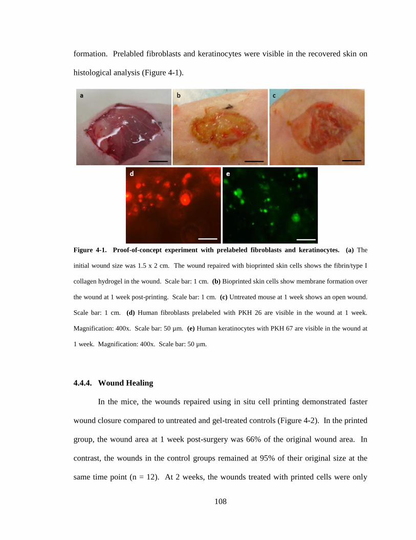
108
formation. Prelabled fibroblasts and keratinocytes were visible in the recovered skin on
histological analysis (Figure 4-1).
4.4.4. Wound Healing
In the mice, the wounds repaired using in situ cell printing demonstrated faster
wound closure compared to untreated and gel-treated controls (Figure 4-2). In the printed
group, the wound area at 1 week post-surgery was 66% of the original wound area. In
contrast, the wounds in the control groups remained at 95% of their original size at the
same time point (n = 12). At 2 weeks, the wounds treated with printed cells were only
Figure 4-1. Proof-of-concept experiment with prelabeled fibroblasts and keratinocytes. (a) The
initial wound size was 1.5 x 2 cm. The wound repaired with bioprinted skin cells shows the fibrin/type I
collagen hydrogel in the wound. Scale bar: 1 cm. (b) Bioprinted skin cells show membrane formation over
the wound at 1 week post-printing. Scale bar: 1 cm. (c) Untreated mouse at 1 week shows an open wound.
Scale bar: 1 cm. (d) Human fibroblasts prelabeled with PKH 26 are visible in the wound at 1 week.
Magnification: 400x. Scale bar: 50 µm. (e) Human keratinocytes with PKH 67 are visible in the wound at
1 week. Magnification: 400x. Scale bar: 50 µm.

109
15% of the original size, while the wounds in the control groups were 40% of the original
size (n = 8). Overall, printed skin cells were able to close the entire wound by 3 weeks
post-surgery compared to 5 weeks for both negative controls. Gross examination
revealed that every printed skin construct formed a clear membrane over the wound at 1
week (Figure 4-3). This membrane became more organized with time until the wound
was completely covered. Organization into fully-formed skin required approximately 10-
14 days.
Figure 4-2. Analysis of wound sizes over 6 weeks. The initial wound area was 7.5 cm2 (L x W: 3 x 2.5
cm). Printed skin constructs show a significantly reduced time to wound closure when compared to
untreated and fibrin/collagen controls. Printed skin closed the wound in 3 weeks compared to 5 weeks for
controls. Wound sizes were analyzed with one-way ANOVA. *p = 0.0000003, n = 12; †p = 0.0161, n = 8;
‡p = 0.0115, n = 8. 4,5,6 wks: n = 4, no statistical difference detected by ANOVA (p = 0.2). Data
presented as mean + standard deviation.
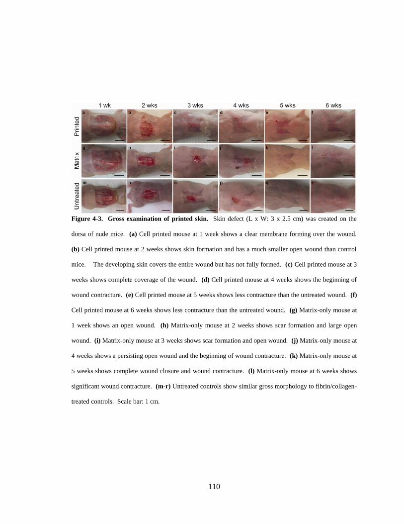
110
Figure 4-3. Gross examination of printed skin. Skin defect (L x W: 3 x 2.5 cm) was created on the
dorsa of nude mice. (a) Cell printed mouse at 1 week shows a clear membrane forming over the wound.
(b) Cell printed mouse at 2 weeks shows skin formation and has a much smaller open wound than control
mice. The developing skin covers the entire wound but has not fully formed. (c) Cell printed mouse at 3
weeks shows complete coverage of the wound. (d) Cell printed mouse at 4 weeks shows the beginning of
wound contracture. (e) Cell printed mouse at 5 weeks shows less contracture than the untreated wound. (f)
Cell printed mouse at 6 weeks shows less contracture than the untreated wound. (g) Matrix-only mouse at
1 week shows an open wound. (h) Matrix-only mouse at 2 weeks shows scar formation and large open
wound. (i) Matrix-only mouse at 3 weeks shows scar formation and open wound. (j) Matrix-only mouse at
4 weeks shows a persisting open wound and the beginning of wound contracture. (k) Matrix-only mouse at
5 weeks shows complete wound closure and wound contracture. (l) Matrix-only mouse at 6 weeks shows
significant wound contracture. (m-r) Untreated controls show similar gross morphology to fibrin/collagen-
treated controls. Scale bar: 1 cm.

111
4.4.5. Histological Analysis
Histological examination of retrieved skin constructs revealed pockets of cells at
1 week post-printing (Figure 4-4). This was expected, because our system delivered
approximately 500 cells per drop using the current prototype. One of the main
advantages of this printing system is rapid coverage of the wound center, which was
demonstrated by the increased cellularity observed in the center of the treated wounds
compared to negative controls. This histological finding supports the observation that a
clear membrane formed over the wounds that were printed with cells, and indicates that
cells were present in the wound but had not yet formed skin at this time point.
Complete closure of the printed wounds by 3 weeks was confirmed by
organization of the skin cells into a fully formed dermis and epidermis (Figure 4-4). In
all printed constructs the dermis contained a highly organized deep reticular layer and a
less-organized papillary layer. All five layers of epidermis were present.
Immunohistochemistry for human cells showed that human fibroblasts and keratinocytes
were still present within the dermis and epidermis of the wound center at 3 weeks (Figure
4-5). Human cells were also present in the surrounding mouse skin, and the number of
human cells present decreased with increasing distance from the wound center. At 6
weeks after treatment, the findings were similar to 3 weeks and the printed skin was more
organized than the skin from the negative controls.

112
Figure 4-4. Masson’s Trichrome examination of skin. (a) Printed skin at 1 week at the edge of the
wound shows pockets of cells integrating with the surrounding skin. The epidermis of the surrounding
undamaged skin blends seamlessly into the printed skin construct. (b) Printed skin at the center of the
wound shows increased cellularity compared to the negative controls, demonstrating the ability of the
printer to treat the entire wound. (c) Printed skin at 3 weeks at the center of the wound shows fully formed
skin. The dermis is organized with two distinct layers and proliferation of the epidermis is slowing as
demonstrated by the small stratum basale. (d) Printed skin at 6 weeks at the center of the wound shows
fully formed skin with organization of the dermis and epidermis. (e) Matrix-only skin at 1 week at the
wound edge shows no integration with the surrounding skin. (f) Matrix-only wound shows few cells and
almost exposes the underlying muscle. A thin layer of collagen is visible over the wound. (g) Matrix-only
wound at 3 weeks shows inflammation and granulation tissue in the wound center and no epidermal
coverage. (h) Matrix-only wound at 6 weeks shows dermis and epidermis but appears less organized than
the printed constructs. (i-l) Untreated controls show similar histological results to fibrin/collagen-treated
controls. Magnification: 100x. Scale bar: 100 µm.

113
Figure 4-5. Immunohistochemistry for human cells. (a) 200x magnification using anti-human nuclear
antigen shows printed skin at the center of the wound with human keratinocytes (brown nuclei) comprising
the epidermis and a mixture of human and mouse fibroblasts in the dermis. Scale bar: 100 µm. (b) 400x
magnification using anti-HLA ABC antibody shows printed skin at the center of the wound with human
keratinocytes (red membrane) comprising the epidermis. Scale bar: 50 µm. (c) 200x magnification of the
wound center using anti-human nuclear antigen shows persistence of human cells in the wound at 6 weeks.
Scale bar: 100 µm. (d) 400x magnification using anti-HLA ABC antibody shows human keratinocytes in
the wound at 6 weeks. Scale bar: 50 µm.

114
4.5. Discussion
Patients with extensive burn wounds present significant treatment challenges.
Difficulty in transporting critically injured patients, inadequate skin substitutes, and poor
cosmetic outcomes are the major problems associated with burn treatment. To overcome
these challenges, a new treatment method that can provide adequate wound coverage and
encourage healing for each individual patient is needed. In addition, because patient
survival is inversely proportional to the amount of time it takes to cover a burn, new
treatment methods must be capable of providing therapy quickly. Because bioprinting
can deliver specific cells to specific target areas in a defined configuration, our proposed
skin cell delivery system allows rapid production of patient-specific wound coverage
while simultaneously obviating the need for specialized manufacturing facilities and cell
culture materials at burn care centers. Our goal for this novel system is to provide rapid
coverage for burn wounds while providing better healing and cosmetic outcomes.
In order to demonstrate proof-of-concept, we began by using our model system to
print a bilayered skin construct consisting of fibroblasts and keratinocytes directly into a
full-thickness skin defect on a nude mouse. We embedded the cells in a matrix of
fibrinogen and type I collagen for three reasons. First, the formation of fibrin from the
reaction of fibrinogen and thrombin produces a strong gel that allows the cells to
maintain their position on the mouse even if the mouse moves. This is a crucial
advantage of our system over skin grafts and other types of artificial skin which can
become necrotic if patient movement tears the graft. Second, fibrin and type I collagen
have already been used to create skin constructs and their properties are well defined for
this application (Grant et al., 2002; Otto et al., 1995). Third, previous attempts to create

115
skin grafts made from autologous cells and artificial matrix in vitro have resulted in grafts
that are extremely fragile and difficult to transport (Pereira et al., 2007). Our
fibrin/collagen delivery matrix eliminates the need to transport a fragile autologous graft
and ensures that the valuable autologous cells will survive transfer to the patient.
After printing, prelabeled fibroblasts and keratinocytes were visible in the
construct 1 week post-printing, indicating that the cells remained in the wound area. We
confirmed that the printed cells remained in the defined wound area at later time points
using immunohistochemistry to differentiate between human and mouse cells in the
wound. Evaluation of the wound area over a 6 week period showed rapid closure of the
wound in the treated mice compared to the negative controls. At 2 weeks post-surgery,
the wounds in the printed mice were open only at the center, in the area of greatest body
curvature. There are three possible explanations for this phenomenon. First, although we
treated the center of the wound, the normal healing process will always begin at the
wound edge and move inward toward the center. Second, we used surgical gauze instead
of non-adherent burn bandages to cover the wounds. Cells can adhere to and infiltrate the
gauze, and we may have lost some of the printed keratinocytes during dressing changes
as a result. In subsequent experiments, we plan to replace the gauze with dressings
similar to those already in use for burn patients. Third, printed cell droplets may have
rolled off the curves of the body before the thrombin could be printed over the cells to
secure them in place. Our latest prototype eliminates this issue by replacing printed
thrombin with a thrombin atomizing nozzle, which creates fibrin more rapidly.
Histological analysis using Masson’s Trichrome staining confirmed the results of
gross examination by indicating that the printed skin constructs possessed a structure

116
similar to normal skin. The epidermis was the same thickness in both the printed
construct and normal tissue. There was a demarcation at the dermal-epidermal junction,
and the dermis in the printed construct appeared to be similar in composition to normal
tissue with both reticular and papillary dermis. This is important because it shows the
ability of the skin delivery system to print tissue that mimics the surrounding skin
structure. Immunohistochemistry for human cells demonstrated that these cells were
present in the wound up to 6 weeks post-printing.
This proof-of-concept experiment shows that in situ skin printing using this
delivery system is a viable method for rapidly generating skin constructs for extensive
wounds. Our system fulfills many of the criteria for an ideal skin substitute. Cells
printed using this system adhere intimately to the wound bed, provide a non-antigenic
microbial barrier, participate in normal host repair mechanisms, maintain elasticity and
long-term durability, display long-term mechanical and cosmetic function comparable to
split-thickness autografts, require a single operation, are inexpensive, and have minimal
storage requirements. The only ideal skin substitute characteristic that is not fulfilled by
this system is the requirement of indefinite storage, which is virtually impossible to
achieve with any living skin substitute. The cartridge system provides the ability to print
either autologous cells or allogeneic cells. Autologous cells require 2-5 weeks to grow in
culture (Pereira et al., 2007; Bello et al., 2001) and are ideal for immunologic reasons but
cannot be used for patients who need wound coverage immediately. However, the
cartridge system allows packing and shipping of allogeneic cells to burn centers which in
turn allows treatment of the wound as soon as the patient is stable and the wound has
undergone debridement, as demonstrated by previous uses of allogeneic skin cells for

117
burn coverage (Flasza et al., 2007; Kuroyanagi et al., 2004; Nunez-Gutierrez et al., 1996;
Rivas-Torres et al., 1996; Tanaka et al., 1999; Yamada et al., 2008; Yonezawa et al.,
2007). A skin biopsy could be taken at the time of the first treatment and later used for
skin resurfacing using one machine with different cartridges.
Additionally, our device may be suitable for treating critically injured patients
who cannot be easily transported, because the printer is designed to be portable and can
be brought to the patient. The device design allows treatment in virtually any hospital
bed or operating room because the system can be quickly transported wherever it is
needed.
Every patient has a different burn wound with different treatment needs. Our
system combines portability with the ability to customize treatment for each individual
wound. The imaging system is the first major component that allows this new system to
customize treatment in this manner. In this system, a laser scanner creates a map of the
patient’s wound. However, the modular design of the software allows any imaging
system to be easily attached to the printing system. In this way our system can quickly
assimilate new imaging technology; for example, recent experiments have tested the use
of orthogonal polarization spectral imaging and ultrasound to evaluate burn depth and
quality of healing (Goertz et al., 2010; Iwamoto et al., 2008). Thus, our system may be
able to provide burn diagnostics as well as burn treatment in one machine. In the future
we envision a device that provides information about the wound to a surgeon in the
operating room to determine how much of the patient’s native skin is viable, and then a
matching skin construct could be printed to fill in the damaged areas.

118
The second major component that allows custom treatment is the cartridge-based
delivery system. While the current study examined only the use of fibroblasts and
keratinocytes in skin printing, the design of the system allows for precise delivery of
additional cell types. These include but are not limited to dermal papilla cells,
melanocytes, and endothelial cells. Including these additional cell types could increase
the similarity between the normal skin structure and the printed construct and provide
both functional and cosmetic improvements over current treatment techniques, especially
with regard to pigmentation and hair follicles. We can also print antimicrobial agents
directly into the wound along with cells to combat infection and sepsis. The print
cartridges can also include factors aimed at improving the function of skin constructs
without any modifications to the system. These include scarless healing reagents, growth
factors, and protease inhibitors to maintain the longevity of other reagents. Any cell type
or reagent that can be packaged into a cartridge can be rapidly delivered to a specific
location on the patient. This property makes our system superior to most current burn
treatments because it eliminates the need for culturing cells and reagents together in a
skin construct prior to patient implantation. It also makes our system suitable for
deployment to forward combat hospitals, where it could be used to treat severely burned
soldiers and non-combatants who cannot be airlifted to burn care centers. In addition, our
system is not limited to delivery directly in the wound – it can also be used to resurface
an artificial skin substitute with cell therapy if a patient requires artificial therapy to
survive. Thus, our design provides a powerful new tool to augment current burn
therapies.

119
However, the current prototype has several areas for improvement related to the
cartridge-based delivery system. As noted previously, inkjet cartridges suffer from
severe clogging issues due to salt deposition in the microfluidic heads during printing.
Thus, single-cell precision for in situ skin printing is unlikely to become a reality until a
viable solution for clogging is found. We chose a pressure-based system to overcome
this problem but our current system is less precise than thermal or piezoelectric
microfluidic printing. Initially we chose to use inkjet valves due to their low cost, but
since we have demonstrated the viability of the in situ printing method we are working to
increase our delivery precision by reducing the valve nozzle diameter from 1.37 mm to
63 µm. Changing nozzle diameters creates a design tradeoff – high precision equals low
throughput and vice versa. Therefore, the final product will most likely include both high
throughput valves for delivering the abundant cell types such as fibroblasts and
keratinocytes and high precision valves for creating complex adnexal structures in situ.
This combination will create a novel treatment method that can provide skin coverage
and functional outcomes for patients with extensive burn wounds.
4.6. Conclusions
This chapter describes the design and use of a novel delivery system for in situ
bioprinting of the skin. The cartridge based system presented here can be easily
transported from patient to patient and can rapidly print skin constructs that mimic
normal skin. In this chapter, we have demonstrated that the concept of in situ skin
printing in mice is a viable technique. This work represents an important new step in
burn care for both the civilian and military populations.

120
References
Bello, Y. M., Falabella, A. F., & Eaglstein, W. H. (2001). Tissue-engineered skin.
Current status in wound healing. Am.J Clin.Dermatol., 2, 305-313.
Binder, K. W., Zhao, W., Dice, D., Tan, J., Kang, H. W., Atala, A., & Yoo, J. J. (2011).
Development of an in situ skin bioprinter for extensive burn wounds. Nat
Biotechnol.(Submitted).
Flasza, M., Kemp, P., Shering, D., Qiao, J., Marshall, D., Bokta, A., & Johnson, P. A.
(2007). Development and manufacture of an investigational human living dermal
equivalent (ICX-SKN). Regen.Med., 2, 903-918.
Goertz, O., Ring, A., Kohlinger, A., Daigeler, A., Andree, C., Steinau, H. U., & Langer,
S. (2010). Orthogonal polarization spectral imaging: a tool for assessing burn
depths? Ann.Plast Surg., 64, 217-221.
Grant, I., Warwick, K., Marshall, J., Green, C., & Martin, R. (2002). The co-application
of sprayed cultured autologous keratinocytes and autologous fibrin sealant in a
porcine wound model. Br.J Plast Surg., 55, 219-227.
Iwamoto, T., Saijo, Y., Hozumi, N., Kobayashi, K., Okada, N., Tanaka, A., &
Yoshizawa, M. (2008). High frequency ultrasound characterization of artificial
skin. Conf.Proc.IEEE Eng Med.Biol Soc., 2008:2185-8., 2185-2188.
Kuroyanagi, Y., Kubo, K., Matsui, H., Kim, H. J., Numari, S., Mabuchi, Y., & Kagawa,
S. (2004). Establishment of banking system for allogeneic cultured dermal
substitute. Artif.Organs., 28, 13-21.

121
Nunez-Gutierrez, H., Castro-Munozledo, F., & Kuri-Harcuch, W. (1996). Combined use
of allograft and autograft epidermal cultures in therapy of burns. Plast Reconstr
Surg., 98, 929-939.
Otto, W. R., Nanchahal, J., Lu, Q. L., Boddy, N., & Dover, R. (1995). Survival of
allogeneic cells in cultured organotypic skin grafts. Plast Reconstr Surg., 96, 166-
176.
Pereira, C., Gold, W., & Herndon, D. (2007). Review paper: burn coverage technologies:
current concepts and future directions. J Biomater Appl., 22, 101-121.
Rivas-Torres, M. T., Amato, D., rambula-Alvarez, H., & Kuri-Harcuch, W. (1996).
Controlled clinical study of skin donor sites and deep partial-thickness burns
treated with cultured epidermal allografts. Plast Reconstr Surg., 98, 279-287.
Tanaka, M., Nakakita, N., & Kuroyanagi, Y. (1999). Allogeneic cultured dermal
substitute composed of spongy collagen containing fibroblasts: evaluation in
animal test. J Biomater Sci Polym Ed., 10, 433-453.
Yamada, N., Uchinuma, E., & Kuroyanagi, Y. (2008). Clinical trial of allogeneic cultured
dermal substitutes for intractable skin ulcers of the lower leg. J Artif.Organs., 11,
100-103.
Yonezawa, M., Tanizaki, H., Inoguchi, N., Ishida, M., Katoh, M., Tachibana, T.,
Miyachi, Y., Kubo, K., & Kuroyanagi, Y. (2007). Clinical study with allogeneic
cultured dermal substitutes for chronic leg ulcers. Int.J Dermatol., 46, 36-42.

122
CHAPTER 5
IN SITU BIOPRINTING OF THE SKIN IN A PRECLINICAL MODEL
5.1. Introduction
As demonstrated in Chapter 4, in situ bioprinting of fibroblasts and keratinocytes
is a viable method for repairing skin wounds. However, the experiment in mice revealed
several areas for improvement. First, bioprinting drops of cells with drops of thrombin
created constructs that were much thicker in situ than in our in vitro tests. This method of
generating skin constructs doubles the water volume of the final construct. The extra
water can escape from the construct in vitro by rolling away from the construct; however,
the edges of the wound bed in vivo prevent this loss of water. Ultimately, this flaw
results in a severe loss of spatial precision. The murine experiment also revealed flaws in
the method of sterilizing and cleaning the feed lines for the inkjet valves. Cleaning the
lines required empty cartridges that could act as a pass-through for air to reach the valves.
A better cartridge design would add the ability to clean the lines without having to
change cartridges.
Finally, the generic bioprinting software was not suited to the demands of skin
bioprinting. The skin delivery system must have knowledge of the structure of skin in
order to properly bioprint skin. A better software design would allow the bioprinter to
create dermal and epidermal structures programmatically rather than forcing the user to
create bitmap images for different structures. This chapter details the improvements

123
made to the initial in situ bioprinting prototype to create a preclinical prototype suitable
for large wounds, and the validation of this system in a preclinical animal model.
5.2. Design Goals
We established the following criteria for the novel system to account for the
difficulties associated with treating patients with large wounds:
1. The system must be portable and capable of being quickly transported to
patients with extensive burn wounds.
2. The system must accommodate a wide range of body types.
3. The system should be capable of tailoring cell therapy to an individual
patient’s specific needs.
4. The system should be easily sterilized.
5. The system allows for repeated treatments.
6. Maintenance of the system is easy and inexpensive.
Design goals 1 and 2 were accomplished using a mobile lightweight frame on
which an XYZ plotting system was mounted. The dimensions of the system are large
enough to cover the torso of an average patient but small enough to easily pass through
most doorframes. Once the system is in position over the patient, powerful locks prevent
movement of the frame while printing cells, thus preserving both the mobility of the
system and its delivery precision. The XYZ axes contribute to delivery precision by
using a belt-driven plotting system capable of 100 µm movements. The X and Y axes are
mounted in an H configuration on the frame and the Z axis is mounted to the XY axes.
This configuration ensures that the majority of the machine weight over the patient is

124
safely secured to the frame. In addition, the independent Z axis allows the delivery
system to track with the curvature of the patient’s body, thus accommodating many
different body types.
Tailoring cell therapy to individual patients was accomplished by combining a
wound scanning system with the cartridge-based delivery system developed and tested in
Chapters 3 and 4. The laser scanner gathers length, width, and depth data about the
wound. Conversion of this data into a functional wound map enables the software to
determine the exact cell composition and thickness of different areas of skin. For
example, a wound encompassing part of the back, the side of the torso, and part of the
chest requires thick skin on the back and thinner skin on the side and chest. The
automation provided by the laser scanner and movement axes ensures that printing the
correct skin composition and thickness is repeatable in a complex wound across the back
and chest. This technology also eliminates human error in generating new skin with a
limited resource such as cells.
Ease of sterilization was accomplished by implementing the proposed
improvements to the printhead, discussed in section 5.3.2. Briefly, in this prototype
sterilization cartridges can be connected to the system without requiring additional empty
cartridges to clear the sterilization fluid. Furthermore, the preclinical prototype allows
the user to clean the feed lines without needing to use additional cartridges. This design
also provides methods for repeated treatments by removing the major obstacles to
replacing cartridges after performing bioprinting. Finally, this new design makes
maintenance of the system much easier than in the initial prototype.

125
5.3. Hardware Design
Figure 5-1. Concept design of the skin delivery system. (a) Trimetric view of system demonstrating in
situ skin printing. A cartridge-based delivery system (1) and laser scanner (2) are mounted on an
independent Z axis (6) which is mounted on a fixed XY platform (4,5). The XY platform is mounted on a
mobile frame (3) that fits over the patient bed. (b) Patient perspective of the skin delivery system
demonstrating multiple rows of nozzles (1) for high-throughput coverage of large wounds. (c-f) Operation
of the skin delivery system. The laser scanner passes over the wound to create a map of the missing skin.
This map is translated into a dermis and epidermis which are printed using fibroblasts and keratinocytes,
respectively. Images courtesy of LabTV (National Defense Education Program, Washington, D.C.).
Reproduced from (Binder et al., 2011).

126
5.3.1. Movement System
The movement system was custom designed and built by Applied Motion
Products, Inc. (Watsonville, CA) and Nook Industries, Inc. (Cleveland, OH). The X and
Y axes are driven by an ELZU belt motor system while the Z axis is driven by an ELSZ
belt motor system (Figure 5-2). Two HT-23 stepper motors drive the ELZU at 1.8°/step
and one HT-17 stepper motor drives the ELSZ.
Figure 5-2. Movement system hardware schematic. (a) The ELZU belt motor system is arranged in an
H configuration to put most of the system weight on the frame. The dual HT-23 stepper motors are shown
on the left with the directional arrows. Crosshairs indicate pulleys that maneuver the belts around the X
and Y axes. The belts are connected such that the X axis moves when the motors spin in opposite
directions. The Y axis moves when the motors spin in the same direction. Moving to a specific point is
represented by the equation Xmotor = XCartesian + YCartesian and Ymotor = XCartesian – YCartesian. (b) The ELSZ belt
drives in one direction only. The HT-17 motor attaches to the gears on the box attached to the belt. (c) The
completed system measures 3 ft (X) x 2 ft (Y) x 1.5 ft (Z). Each axis is equipped with limit switches that
provide methods to stop the motors when the carriage reaches the end of the axis. In addition, encoders
attached to the motors signal the number of steps that the motor moves.

127
5.3.2. Delivery System
The delivery system was improved to overcome the obstacles outlined in section
5.1 (Figure 5-3). First, the cartridge system was outfitted with clean air feeds and waste
Figure 5-3. Skin Delivery System cartridges, printhead, and flow schematic. (a) Each cartridge has a
pressure inlet and an outlet connected two 3-way stopcocks. All connections are made using Luer locks to
prevent disconnection. Manipulating the stopcock inlets and outlets directs the flow of material to different
locations. This cartridge setup can hold up to six different materials. The rear central tube remains empty
to act as a source of clean air. The large tubes on the right are waste reservoirs. (b) Side view of printhead.
This particular printhead uses four inkjet valves connected in pairs to provide rapid delivery of the contents
of a cartridge. The laser pointer is visible on the left. (c) Top view of printhead. The two atomizing
nozzles are visible between the pairs of inkjet valves. Electrical connections are made using the connectors
mounted to the edges of the printhead. (d) Flow schematic demonstrating the possible paths for material to
flow through the delivery system. (Red) Material from the cartridge defaults to moving straight through
the primary stopcock to the printhead. (Green) Manipulating the stopcock directions shunts material from
the cartridge into the waste reservoir. This enables the user to quickly rid the machine of all material in the
cartridge. (Yellow) Clean air flows from the empty tube to the printhead. This enables the user to clean
the feed lines without needing to use a separate empty cartridge.

128
reservoirs to assist with cleaning and sterilizing the feed lines. Instead of using a single
output for each cartridge, the upgraded delivery system uses dual three-way stopcocks
connected to each cartridge to direct the flow of material. The dual stopcocks provide
two inlets fed by the cartridge and the clean air and two outlets leading to the printhead
and waste reservoir. Clean air allows the user to quickly clear the feed lines to the inkjet
valves while the waste reservoir clears the feed line in the cartridge.
The printhead is interchangeable with printheads from the initial prototype;
therefore, the results of in situ skin bioprinting in a murine model can be directly
translated to the preclinical prototype. However, the inkjet valves that bioprinted
thrombin were replaced with atomizing nozzles mounted between the valves. These
nozzles spray thrombin over a wide area, cross-linking much of the bioprinted construct
at once. The atomizers eliminate the resolution errors that occurred when thrombin was
bioprinted in equal amounts with the fibrinogen/type I collagen solution.
5.3.3. Scanning System
The scanning system uses a NextEngine® (NextEngine Inc., Santa Monica, CA)
laser scanning system to gather length, width, and depth information about a wound.
This desktop 3D scanner has dimensions 8.8 in (X) x 3.6 in (Y) x 10.9 in (Z). The
scanner uses an array of lasers combined with dual 3.0 megapixel RGB (red, green, blue)
cameras to gather three-dimensional data. The resolution of the scanner is 400 dots-per-
inch (DPI) in Macro Mode and 150 DPI in Wide Mode. Once the data has been acquired
the ScanStudio™ software included with the scanner converts the data into an STL
model. Unfortunately, the NextEngine scanner does not include application

129
programming interfaces to integrate the scanner directly into the skin delivery system
software. Instead, the STL model is converted into a series of XYZ lines by software
graciously developed by Dr. Hyun-Wook Kang. These lines are transformed by first
creating a model surface of the STL data. Next, this surface is converted into a negative
model that corresponds to the model surface. The height of this negative is defined by
the user. This step is required because the skin delivery system is not bioprinting the
model defined by the laser scanner; rather, it needs to bioprint the negative model that fits
within the scanned area. After the negative model has been created it is converted into a
series of Z layers of thickness defined by the user. Each of these layers is overlaid with a
series of XY lines that represent the area to be bioprinted. Finally, these XY lines along
with the Z layers are converted to plain text to be imported into the skin delivery system
software (Figure 5-4).
Figure 5-4. Sample output of laser scanner integrated with
skin delivery system. (Top) A surface measurement is converted
into a three-dimensional object model representing the negative
model of the measured surface. This model is sliced into layers along the Z axis and each layer is overlaid
with lines representing the printing path. These lines are converted into generic text that is imported into
the skin delivery system. (Right) Sample output from the laser scanner. This generic interface provides a
Z value for each layer and the start and end positions in X Y coordinates for each line to be printed.

130
5.4. Software Design
5.4.1. Interface Component
The major components of Bioprinter v2.0 did not significantly change in the
upgrade to the preclinical prototype. This is a major advantage of object-oriented
programming in that existing code can be ported to new applications without affecting
the rest of the program. Each of the components was converted from a generic
bioprinting object to a code specifically designed for skin bioprinting. The Interface
component maintains backwards compatibility with the image parsing algorithms
Figure 5-5. Skin delivery system software schematic. The three-tier design present in Bioprinter v2.0
was upgraded to include the new components for the preclinical prototype skin bioprinter. Arrows indicate
direction of communication. (Red) Major components taken from Bioprinter v2.0 are able to
accommodate the new system without significant changes due to the object-oriented architecture. (Green)
Hardware components now include the scanning system in addition to the printing system. (Purple)
Encapsulating components include an upgrade of the Organ object and the new Printhead object that
maintains data for each valve and the cell types connected to the cartridges. (Blue) Data components hold
the data for each object. The encapsulating components separate the data components from the rest of the
software and allow the data components to change without affecting other components.

131
described in Chapter 3. However, Interface now uses those algorithms as specific
methods to create skin constructs.
Since Interface is backwards compatible with Bioprinter v2.0, it allows the user to
bioprint skin constructs using either the scale prototype developed in Chapter 3 or the
preclinical prototype developed in this chapter. This option is presented to the user upon
starting the program in the Interface_Load function (p. 325). In similar fashion to the
Bioprinter v2.0 Load function, this function also pulls the default system configuration
and the default printhead into memory. These configuration files are created using the
upgraded configuration form (Figure 5-6).
Figure 5-6. Skin delivery system configuration manager. This form allows the user to change
acceleration and velocity settings for the Applied Motion motors. The X and Y motors are listed together
because the two motors must always run at the same speeds. The serial port numbers for the hardware
communications are stored in drop down boxes on the left. Dwell times for the valves are stored as text as
are the offsets for the laser pointer. Each value has specific ranges that are checked when the user saves or
loads a configuration.

132
The default configuration contains the following information in plain text stored in a
*.sdscfg file:
1. Valve serial port number
2. Plotter serial port number
3. Dwell time for inkjet valves
4. Dwell time for atomizing valves
5. Laser pointer X offset
6. Laser pointer Y offset
7. Wait status represented as a Boolean value
8. X and Y axis acceleration, revolutions/sec/sec
9. X and Y axis maximum acceleration, rev/sec/sec
10. X and Y axis deceleration, rev/sec/sec
11. X and Y axis jog acceleration, rev/sec/sec
12. X and Y axis jog deceleration, rev/sec/sec
13. X and Y axis jog speed, rev/sec
14. X and Y axis change speed, rev/sec/sec
15. X and Y axis velocity, rev/sec
16. Z axis acceleration, revolutions/sec/sec
17. Z axis maximum acceleration, rev/sec/sec
18. Z axis deceleration, rev/sec/sec
19. Z axis jog acceleration, rev/sec/sec
20. Z axis jog deceleration, rev/sec/sec
21. Z axis jog speed, rev/sec

133
22. Z axis change speed, rev/sec/sec
23. Z axis velocity, rev/sec
The serial port numbers and the dwell times are used by the Plotter object to establish
communications with the bioprinting system. The laser pointer offsets are used by the
parsing algorithms to determine the starting point for the skin construct to be bioprinted.
The wait status is used in communications with the bioprinting system and will be
discussed in section 5.4.7. All of the acceleration, deceleration, and velocity values must
be sent to the controllers for the Applied Motion motors before movement begins or the
movement system may exhibit unexpected behavior.
Figure 5-7. Skin delivery system configuration manager for printhead development. (Left)
Parameters for creating printhead configuration are arranged by rows. For each row the user defines the
number of valves on a row and the spacing between these valves. Valves on a row are subdivided into sets
that define the cell type for that set. For example, a row consisting of valves that bioprint fibroblasts would
be one set of fibroblasts. (Right) Sample printhead configuration showing 5 rows of valves.

134
The default printhead is stored in a *.sdsphd file. The information for each valve
is stored in plain text in the following format: valve set, X location (cm), Y location (cm),
cell type. Each entry is delineated by a | symbol acting as a data spacer. Configuring a
printhead (Figure 5-7) requires the use of the Printhead and Valve objects (p. 333)
discussed in 5.4.5.
Upgrades to the Interface object also include modifications to the Print Controls
menu to facilitate bioprinting skin structures (Figure 5-8). Chief among these
modifications is the addition of the laser scanner data to the bioprinting system. Since the
NextEngine scanner does not provide application programming interfaces to integrate the
scanner in the software, this option signals the Database object to import the scanner data
from the text file discussed in section 5.3.3. As previously described, the laser scanner
data is split into layers along the Z axis. The Print Controls menu requires the user to
define the depth along the Z axis at which the dermis and epidermis split. All layers
below this depth are bioprinted using dermal components and all layers above this depth
are bioprinted using epidermal components. Another major change to the Print Controls
menu is the Available Cell Types menu that is populated by importing the cell types
defined by the Printhead object. This menu enables the user to choose which cell types
to bioprint without needing to define the specific valves to use. Furthermore, this menu
allows the software to determine how to bioprint adnexal structures such as hair follicles
and pigment. Selecting one of these components in the Available Cell Types menu
prompts the user to define additional values for the number of bioprinted cell drops in the
adnexal structure and additional spacing between these cell drops. For example,
bioprinting hair follicles may require single fibroblast cell drops spaced 1 mm apart with

135
four drops of dermal papilla cells spaced 4 mm apart. The Print Controls menu provides
this functionality, facilitating the transition of the skin delivery system from a method of
bioprinting fibroblasts and keratinocytes to an enabling technology to bring new wound
therapies to the clinic.
Figure 5-8. Main window of Skin Delivery System with Print Controls menu displayed. (Left) The
controls for manipulating the operation of the bioprinting system remain the same as Bioprinter v2.0.
(Right) The Available Commands were reduced to operations required for skin bioprinting. The Available
Cell Types CheckedListBox replaces the parameters that were present in Bioprinter v2.0. The Available
Cell Types are populated by reading the attached cell types from the Printhead. The Do Command
algorithm passes to the path algorithms the cell types to be bioprinted. Data from the scanning system is
imported to the bioprinting system by selecting the Use Laser Scanner Data option. This option requires
the user to set the depth of the dermal/epidermal split.

136
5.4.2. Logic Component
Most of the Logic component remained unchanged in the transition from
Bioprinter v2.0 to Skin Delivery System. The object still acts as a communications hub
among the software components and maintains proper thread control for the interface
thread and the hardware thread. The only major changes were the conversion of the
Organ object to the Skin object and the addition of the Printhead object as a child object
of the Logic component.
5.4.3. Database Component
Similar to the Logic component, the Database component remained mostly
unchanged in the program transition. New functions for saving and opening the
Printhead object were added (p. 356). The major addition to the Database component
was the interaction with the text file from the laser scanner in Database_Open Skin Map
(p. 358). This function takes as parameters the file path of the text file and the Skin
object from the Logic component. The Database object interprets the text file (Figure 5-
4), instructing the Skin object to add a new layer each time a "Z Layer" line is reached
along with the depth value of that layer. Within each layer, the Database object parses
the start and end positions of each line from the XY data and instructs the Skin object to
add a new line to the current Z layer. The running time of this algorithm is linear with
respect to the number of lines in the scanner data.

137
5.4.4. Skin, SkinLayer, and PathLine Components
The Skin object is similar to the Organ object discussed in Chapter 3. Each Skin
object is composed of SkinLayer objects representing the Z layers of the data from the
laser scanner. The major difference between Organ and Skin is that the Skin object
maintains information about the skin construct that is relevant to bioprinting skin.
Specifically, the Skin object determines which Z layers correspond to the dermis and
epidermis defined by the user with the dermal/epidermal split value (p. 361). Skin
maintains the list of Z layers in a System::Collections::ArrayList of SkinLayer objects.
The SkinLayer object maintains the XY data for a Z layer in a
System::Collections::ArrayList of PathLine object. A PathLine object holds the start and
end points for a line from the laser scanner data. SkinLayer generates a bioprinting path
from these lines in the SkinLayer_ProcessLayer by taking as parameters the spacing
between cell drops, the cell types to be bioprinted, and the Printhead object holding the
data for the physical locations of the inkjet valves (p. 370). The algorithm begins by
getting the maximum values for the X and Y locations of the valves for each different cell
type. These values are used to determine when a valve passes beyond the boundary of
the current PathLine. The function iterates through each PathLine and imposes the
physical locations of the valves for each cell type on the line. Each point at which a
valve is successfully placed on a line is added to the bioprinting path in the format
(X,Y)ValveNumber[. Each valve that is fired at a specific point is separated from the
other valves by the [ symbol. All valves in the printhead could potentially be fired at one
time. This generic format enables the Plotter Handler object to interpret the data from
the Skin object with minimal alterations to the existing Plotter Handler object. The Skin

138
object iterates through each SkinLayer object to gather the bioprinting paths for each
layer.
5.4.5. Printhead and Valve Components
As previously indicated, the Printhead component maintains the data for different
printheads. Since the delivery system printheads are interchangeable (section 5.3.2), the
ability to store and retrieve printhead information makes switching from a high-
throughput printhead to a high-precision printhead as simple as loading a different
printhead file. The Printhead object exposes methods for storing and manipulating Valve
objects. Valve objects store the following information for each inkjet valve:
1. Valve number – 32 bit integer
2. Valve set number – 32 bit integer
3. X location (cm) – 32 bit double precision floating point
4. Y location (cm) – 32 bit double precision floating point
5. X location (pixels) – 32 bit double precision floating point
6. Y location (pixels) – 32 bit double precision floating point
7. Cell type – System::String
Each of these values is provided by the configuration manager in the Interface
component. Printhead arranges the valves by rows and can return the valves by row, set,
or cell type (p. 370).

139
5.4.6. Plotter Handler Component
Since Plotter Handler does not have knowledge of the hardware interface with the
bioprinter, most of the code did not change in the upgrade to Skin Delivery System. One
major change was the ability to bioprint using multiple valves simultaneously. This
addition takes the form of a do…while loop to iterate through the valve numbers provided
by the Skin object and pass them to the Plotter object (p. 386). The rest of the algorithm
for bioprinting a series of points did not change.
Another major upgrade to the Plotter Handler component lied in the
CreateEvenlySpacedPoints algorithm (p. 393). The purpose of this function is to provide
a method for the user to bypass the image parsing and laser scanning algorithms.
Therefore, the code for bioprinting adnexal structures such as hair follicles and
melanocytes must be duplicated from the parsing algorithm in the SkinLayer object. The
major difference between the CreateEvenlySpacedPoints algorithm and the SkinLayer
algorithm is that CreateEvenlySpacedPoints is free to place points wherever they are
needed instead of being wedded to the laser scanner data. Thus, this algorithm can use
the Printhead data to create the bioprinting path for a skin construct programmatically.
5.4.7. Plotter Component
The encapsulation of the Plotter component in the architecture of Bioprinter v2.0
enabled the interactions with the hardware to change without affecting the rest of the
program. The first major change in hardware communications was the addition of a
second System::IO::SerialPort object. This new serial port communicates with the
Applied Motion movement system while the existing serial port communicates with the

140
custom hardware that drives the delivery system. Crucially, the Applied Motion system
cannot interact with the serial port buffer that was used in Bioprinter v2.0. Therefore, the
software reads and writes data directly to the input/output stream for the SerialPort object
(p. 416). When the program initiates any movement, the Plotter object ensures that the
Initialize function transmits the configuration settings for each motor to the Applied
Motion system (p. 434). This safety check ensures that the motors do not exhibit
unexpected behavior.
Movement is achieved by implementing the conversion equations for the motors
(Figure 5-2). There are two different types of move commands. The first is a continuous
move or jog. In this case, Plotter sends the DI (direction) command to the movement
system to set the proper direction followed by the CJ (commence jog) command to start
the jog (p. 422). The stop command consists of sending the SJ (stop jog) command
followed by SP0 (set position) which sets the current position to be 0 (p. 424). Without
the SP0 command the movement system would move back to its original location before
beginning the next move. The second type of move is a discrete move for bioprinting
purposes. This command uses the FL (feed to length) command to move the motor a
specified number of steps instead of using a continuous move.
The Write function is similar to the existing function from Bioprinter v2.0 with
the exception of the valves to use for bioprinting (p. 426). Skin Delivery System can use
more than one valve simultaneously and the upgraded Write routine reflects this
functionality. The valve numbers passed by the Plotter Handler object bitshift the
number 1 by the valve number to create a binary representation of the valve numbers for
up to 8 valves. For example, valve 2 would be represented by 00000010b whereas valves

141
3 and 7 would be represented as 01000100b. These values are passed to the hardware
controlling the delivery system after the movement system has completed its move. It is
only in the Write algorithm that the offsets for the laser pointer are applied to the location
of the move. This encapsulation enables the rest of the program to forego knowledge of
the hardware implementation while still producing viable bioprinting paths. Write can
also operate the hardware for Bioprinter v2.0.
After the data has been sent to the hardware (p. 434), the Plotter object waits in a
manner defined by the user. This definition comes from the user selecting Block or Poll
in the configuration manager. Block uses a System::Threading::EventWaitHandle to
block the current thread until the movement system signals completion of the move. Poll
sends status requests to the movement system to determine if the move is complete. Both
types of waiting achieve the same goal. Block is faster but is susceptible to interruptions
in communications. Poll is significantly slower than Block but can alert the user to
problems with the movement system immediately.
5.5. Summary of Preclinical Prototype
In this aim we designed a device for in situ skin bioprinting in a preclinical model.
The upgraded prototype now includes a scanning system to gather length, width, and
depth information about a wound to guide the delivery system. The flaws of the delivery
system used in the murine model were addressed; the new delivery system is much easier
to sterilize and provides more accurate delivery than the previous prototype.

142
5.6. Preclinical Study
5.6.1. Methods
5.6.1.1. Animal Model
All animal studies were performed according to protocols approved by the Wake
Forest University Health Sciences Animal Care and Use Committee (WFUHS ACUC)
and the United States Army Medical Research and Materiel Command Animal Care and
Use Review Office (USAMRMC ACURO). This experiment was performed in a
porcine wound model because porcine skin is similar to human skin. The bioprinting
procedure was divided into two stages. In the first stage skin from the shoulder area was
removed using a dermatome for preparation of fibroblasts and keratinocytes for
bioprinting. After expanding these cells in culture, four full-thickness 10 cm x 10 cm
wounds were excised through the panniculus carnosus layer of the thoracic dorsa on the
animals (Figure 5-9). This wound size was chosen to simulate the conditions of a large
skin wound where the wound edges are sufficiently far apart that they cannot interact.
Each wound received a different treatment: no treatment, fibrin/type I collagen only,
allogeneic fibroblasts and keratinocytes embedded in fibrin/type I collagen, and
autologous fibroblasts and keratinocytes embedded in fibrin/type I collagen. Wounds
were bandaged with non-adherent Tefla bandages, sterile gauze, Ioban™ adhesive wound
dressing (3M, St. Paul, MN), and Coban™ elastic wrap (3M). Wound size, contracture,
and re-epithelialization were measured weekly using a digital camera at a fixed focal
length. Bandages were changed weekly and animals were monitored daily for signs of
infection and damage to the bandages.

143
5.6.1.2. Skin Cell Isolation
Skin tissue was placed in Gibco® DMEM high glucose medium (Invitrogen Life
Sciences, Carlsbad, CA) with 10% fetal bovine serum (FBS) and 10%
penicillin/streptomycin/amphotericin B (PSA) after harvesting from the animal. The
harvest area was shaved prior to harvesting skin and remaining hairs were manually
removed with forceps prior to cell isolation. Tissue was kept at 4°C until cell isolation
began. The skin was trimmed to ensure 2-3 mm thickness throughout the tissue. After
trimming, skin was rinsed with 10% PSA in sterile phosphate-buffered saline (PBS)
twice followed by a rinse with 1% PSA in PBS. Each piece of skin was cut using a
sterile scalpel into sections measuring approximately 5 mm x 5 mm because smaller
pieces are more conducive to separation of the dermis and epidermis. These pieces of
skin tissue were placed in Dispase II solution (Roche Applied Science, Indianapolis, IN)
in a 50 mL conical tube at 4°C for 16 hours. Each tube was agitated during the isolation
Figure 5-9. Schematic representation of wound sites in the preclinical model. Skin was first removed
from the area just above the shoulder using a dermatome (Skin Biopsy Site). One site was used to gather
cells with the second site remaining untouched in the event that more cells needed to be harvested. After
skin cells were prepared for bioprinting, four areas of thoracic dorsal skin measuring 10 cm x 10 cm were
excised through the panniculus carnosus layer (Wound Area).
144
process to improve absorption of dispase into the skin. Once the dispase digestion was
complete the dermis and epidermis in each piece of skin were manually separated using
sterile forceps.
Dermal fibroblasts were obtained by immersing the pieces of dermis in a solution
of 0.35% type I collagenase in DMEM high glucose with 1% PSA for 60 minutes with
agitation. Agitation continued until there were no visible pieces of tissue. The tissue
slurry was passed through a 100 µm cell strainer to obtain a cell suspension. Finally, the
cell suspension was plated on tissue culture dishes using a culture medium consisting of
DMEM high glucose, 10% FBS, and 1% PSA.
Epidermal keratinocytes were obtained by immersing the pieces of epidermis in a
solution of Gibco® TrpLE at 37°C for 15 minutes. An equal amount of Gibco®
Keratinocyte Serum Free Medium (KSFM) was added to neutralize the enzyme. Cells
were obtained by gentle agitation of this suspension. Too much agitation results in
damage to the cells of the stratum basale and too little agitation prevents isolation of
proliferative keratinocytes. As discussed in Chapter 1, proliferative keratinocytes are
positive for keratin 14. The tissue slurry was passed through a 100 µm cell strainer to
obtain a cell suspension. Keratinocytes must be centrally plated to facilitate growth.
5.6.1.3. Cell Preparation
Initial tests bioprinting a 10 cm x 10 cm skin construct in vitro demonstrated that
the printhead designed for the murine experiments did not have a throughput high enough
to complete the bioprinting procedure in a reasonable amount of time. A bilayered 100
cm2 skin construct took 120 minutes to bioprint with the dual valve system used in

145
Chapter 3. Therefore, a high throughput printhead (Figure 5-3) was developed to
overcome this issue. This printhead feeds a single cell type through four valves
simultaneously to complete a 100 cm2 bilayered skin construct in approximately 45
minutes.
Unlike the murine experiment, the fibroblasts and keratinocytes used in this
experiment cannot be recovered from the skin construct with immunohistochemistry.
The autologous cells have no markers distinct from the native tissue. Prelabeling the
bioprinted cells is the only way to visualize these cells within the skin construct. Prior to
bioprinting, cells were prelabeled with Molecular Probes® CM-DiI (Invitrogen Life
Sciences, Carlsbad, CA). DiI, CM-DiI, DiO, and DiD are lipophilic carbocyanine
membrane intercalators. CM-DiI was chosen for this study because it does not
photobleach and is stable in cell membranes through aldehyde fixation by incorporation
of a chloromethyl substitute. However, cell division dilutes the amount of CM-DiI in the
membrane, reducing the emitted fluorescence over time. Cells were prelabeled with CM-
DiI by removing the culture medium from each plate and adding 50 uL CM-DiI solution
to 10 mL sterile PBS at 37°C. Cells were incubated with CM-DiI for 20 minutes. After
the initial incubation, cells were washed with 10 mL PBS by adding the PBS and
incubating for 10 minutes. This PBS was removed and replaced with culture medium.
Cells were returned to the incubator until they were prepared for bioprinting.
Fibroblasts and keratinocytes were prepared for bioprinting by detaching the cells
from the tissue culture plates by incubating with 10 mL Gibco® 0.05% trypsin in
ethylenediaminetetraacetic acid (EDTA) for 6 minutes at 37°C. Cells were centrifuged at
1500 rpm for 5 minutes to obtain a cell pellet. Simultaneously, bovine plasma fibrinogen

146
type I-S (Sigma-Aldrich, St. Louis, MO) was prepared at 50 mg/mL in PBS and rat tail
type I collagen (BD Biosciences, San Jose, CA) was prepared at 2 mg/mL in PBS. Equal
amounts fibrinogen and type I collagen were combined to create a hydrogel solution with
final concentrations of 25 mg/mL fibrinogen and 1 mg/mL type I collagen. Cell pellets
for one cell type (e.g. autologous fibroblasts) were combined into one cartridge and the
final pellet was resuspended in 12 mL fibrinogen/type I collagen. Thrombin extracted
from bovine plasma (Sigma-Aldrich) was prepared at 50 IU/mL in PBS.
5.6.1.4. Wound Creation and Bioprinting Procedure
Prior to surgery, the printhead, cartridges, and tubing were sterilized with 70%
ethanol by leaving the tubing system and valves filled with ethanol overnight and
flushing with 70% ethanol and autoclaved nanopure water immediately prior to printing.
The inkjet valves cannot be placed in a steam autoclave because they melt. The valves are
also completely airtight when not electrically open (otherwise the valves would
constantly drip cells even when turned off) so gas sterilization cannot penetrate the inside
of the valve. No part of the printer was in direct contact with the animal at any point
during the printing procedure. Surgical procedures were performed with steam
autoclaved instruments and personnel who had contact with the wound area scrubbed for
surgery and wore sterile surgical gowns and gloves.
All experiments in animals were performed aseptically under general anesthesia.
The animals were first sedated and anesthetized with a combination of 20 mg/kg
ketamine, 2 mg/kg xylazine, and 1 mg/kg acepromazine. Anesthesia was maintained
using inhaled 3% isoflurane via endotracheal tube. The wound areas were depilated by

147
shaving before surgery. Dorsal skin was cleaned with water and soap and sterilized with
β-iodine and 70% alcohol. For the creation of the defect, 4 skin wounds were created by
removing 10 x 10 cm of full thickness skin in the central back along the thoracic and
lumbar area. Incisions were made along the wound edges with a surgical blade to the
panniculus carnosus layer and the overlying skin was excised. The wound edges were
tattooed at 5 cm intervals.
Subsequently, the wound area was placed under a portable bioprinter and dermal
cells and matrices were directly bioprinted onto the wound bed. One layer of 10 million
fibroblasts (1.0 x 10⁵ cells/cm
2) was bioprinted at 2 mm intervals between drops with
thrombin sprayed from the atomizing nozzles simultaneously to form a fibrin/type I
collagen hydrogel. 15 minutes was allotted to allow complete conversion of fibrinogen to
fibrin. One layer of 10 million keratinocytes was bioprinted above the fibroblast layer.
The wounds were covered with topical antibiotic cream, Tefla® non-adherent bandages,
Ioban, elastic bandages, and stockinettes. Pain management after the excisional model
consisted of a transdermal fentanyl patch placed on the cervical dorsum or rear flank 24
hours prior to surgery, buprenorphine injection given 6-8 hours post-surgery, and oral
carprofen for 3-5 days.
5.6.1.5. Histology
After euthanasia, 12 mm punch biopsies were taken from the centers of each
wound. These skin samples were fixed in 10% phosphate-buffered formalin overnight at
room temperature. Samples were dehydrated in a graded series of ethanol concentrations,

148
embedded in paraffin, and cut into 5 µm sections. Sections were stained with
hematoxylin and eosin or 4',6-diamidino-2-phenylindole (DAPI).
5.6.2. Results and Discussion
5.6.2.1. Operation of the Skin Delivery System
The skin delivery system achieved nearly every design goal set in section 5.2.
The portable design allowed us to easily move the system to and from the operating
room. Moving the source of air pressure was much more difficult than moving the
delivery system; this flaw will be corrected in a future prototype. We were able to use
the cartridge-based delivery system to precisely deliver autologous and allogeneic
fibroblasts and keratinocytes in a fibrin/type I collagen matrix by attaching different cell
cartridges as necessary. However, the delivery system was not able to maintain
bioprinted cells on areas of significant curvature even with the addition of the atomizing
nozzles for thrombin delivery.
Although we were able to map the wounds with a laser scanner (Figure 5-10), the
breathing motion of the animals resulted in inconsistent depth measurements. The final
output of the laser scanner combined a sine wave with the wound map; these signals
cannot be separated from each other. These errors did not significantly affect the final
output in this experiment because these wounds have a uniform depth and defined edges.
However, the scanning system will need to be upgraded and corrected in the next
prototype.

149
5.6.2.2. Wound Healing Analysis
Wounds were imaged weekly at a fixed focal distance during bandage changes.
Wound size, contracture, and re-epithelialization were evaluated using ImageJ software
(National Institutes of Health, Bethesda, MD). Statistical analysis was performed in the
S-Plus statistical analysis package (TIBCO Software Inc., Palo Alto, CA) using one-way
analysis of variance (ANOVA) followed by Tukey's range test.
Full-thickness skin wounds repaired by bioprinting 10 million autologous
fibroblasts and 10 million autologous keratinocytes showed complete re-epithelialization
at 8 weeks. These skin constructs showed formation of epithelium in the center of the
wound at 2 weeks (Figure 5-11). Keratinocytes in these skin buds proliferated over the
course of 8 weeks to completely cover the wound. The formation of proliferative
Figure 5-10. Operation of the skin delivery system. (a) The laser scanner completes a pass over a full-
thickness excisional wound on the dorsum of a pig. The wound is approximately 5 mm deep. Data from
the laser scanner is converted to create a map for bioprinting skin. (b) A laser pointer guides the printhead
to the upper left corner of the wound to begin bioprinting. This particular printhead is designed for high-
throughput delivery of fibroblasts and keratinocytes in a large wound. Four inkjet valves deliver cells and
two atomizers deliver thrombin for cross-linking fibrinogen.
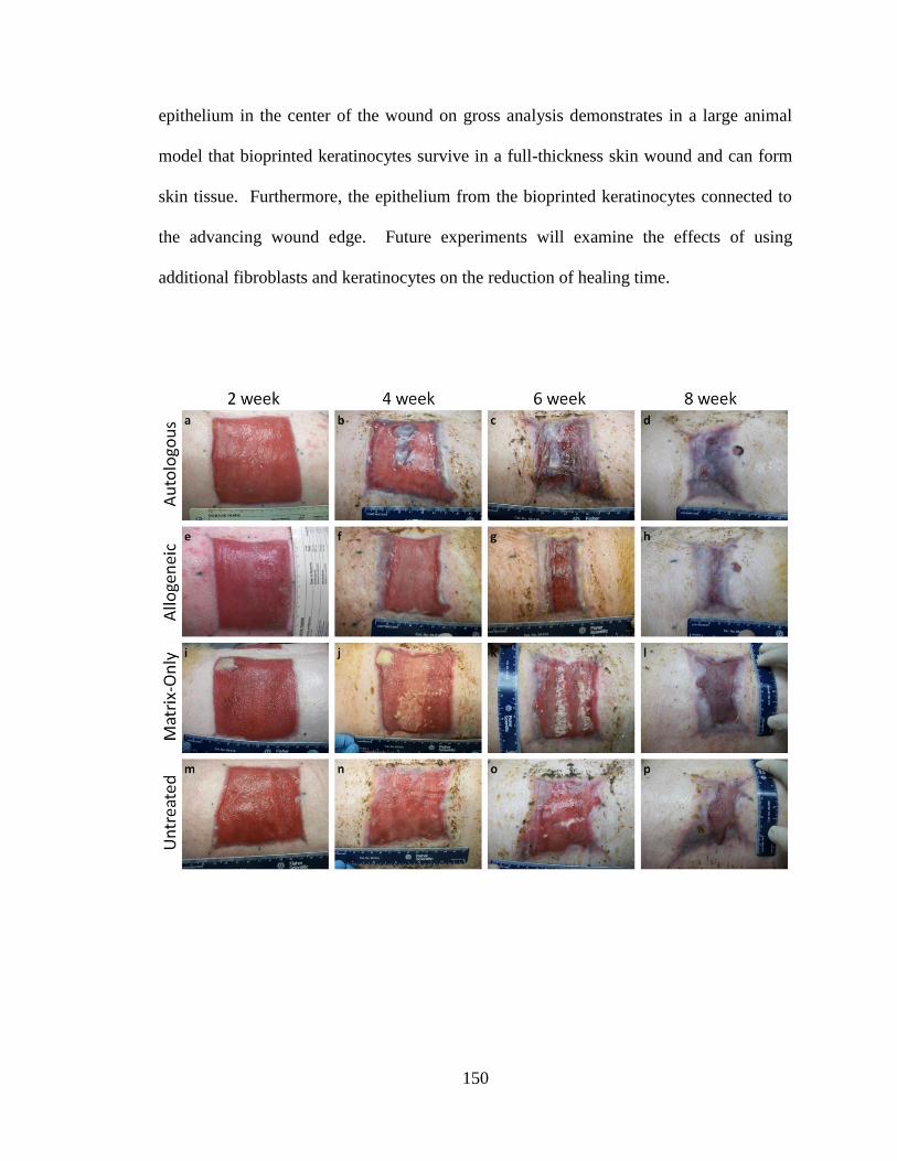
150
epithelium in the center of the wound on gross analysis demonstrates in a large animal
model that bioprinted keratinocytes survive in a full-thickness skin wound and can form
skin tissue. Furthermore, the epithelium from the bioprinted keratinocytes connected to
the advancing wound edge. Future experiments will examine the effects of using
additional fibroblasts and keratinocytes on the reduction of healing time.

151
However, similar results were not seen with bioprinted allogeneic fibroblasts and
keratinocytes. New epithelium was not evident in the wound center nor did the wound
edge advance faster than the negative controls. Neither the fibrin/type I collagen negative
control nor the untreated control healed at 8 weeks. One fibrin/collagen control wound
increased slightly in size at 1 week and one untreated wound greatly contracted at 4
weeks, resulting in wound size data that was skewed high for the fibrin/collagen group
and skewed low for the untreated group. These effects are pronounced due to the low
sample size.
Wound size is a measure of the advancing tissue from the undamaged surrounding
skin (Figure 5-12). No statistically significant differences were detected in the wound
sizes with the exception of the 4 week data; however, the power of this study was not
high enough to avoid type II errors. The increase in wound size in the one fibrin/collagen
control wound is likely due to confounding effects from the animal damaging the wound
edge. Without that outlier there are no statistically significant differences in the wound
sizes at any time points. This result indicates that bioprinting 10 million fibroblasts and
10 million keratinocytes does not affect healing from the surrounding normal skin on the
wound edge. There are two possible explanations for this result. First, the bioprinted
Figure 5-11. Comparison of four different wound treatments over 8 weeks. Treatment groups:
autologous fibroblasts and keratinocytes, allogeneic fibroblasts and keratinocytes, fibrin/type I collagen
alone, and no treatment. (a-d) Circles of epithelialization are present in the centers of the wounds treated
with autologous fibroblasts and keratinocytes. These areas increased in size over 8 weeks to cover the
entire wound area. (e-h) Treatment with allogeneic cells showed no statistically significant difference in
epithelialization over negative controls; however, prelabeled allogeneic fibroblasts and keratinocytes were
present in the wound. (i-p) Wounds treated with fibrin/type I collagen alone and wounds that received no
treatment did not achieve full epithelialization at 8 weeks.

152
fibroblasts and keratinocytes may not affect proliferation of the wound edge. This is
unlikely because of the wide array of growth factors and cytokines produced by skin cells
in a wound bed (Chapter 1). Second, the number of bioprinted cells may have been too
low to affect the surrounding tissue. This explanation is most likely given the 6-8 weeks
required to fully epithelialize the wound with autologous cells in this experiment. If the
bioprinted cells healed the wounds faster, then the cells from the wound edge would not
need to proliferate into the wound. Future experiments will use more fibroblasts and
keratinocytes to examine the effect of cell number on proliferation of the wound edge.
Figure 5-12. Analysis of wound sizes over 8 weeks. Wound size was measured using ImageJ software to
evaluate the total area encompassed by the wound edges including new epithelialization. The initial wound
size was 100 c m2. Data were analyzed by one-way ANOVA followed by Tukey's range test on statistically
significant ANOVA tests. Significance was defined as p < 0.05, n = 3. ^: significant versus fibrin/type I
collagen (matrix-only) negative control. Wound size was not significantly different across treatment
groups with the exception of the matrix-only group at 4 weeks. Overall, wound size was not significantly
affected by treatment with skin cells. This expected result indicates that bioprinting 10 million fibroblasts
and 10 million keratinocytes did not significantly affect advancement of the wound edge from the
surrounding normal tissue. Data presented as mean + standard deviation.
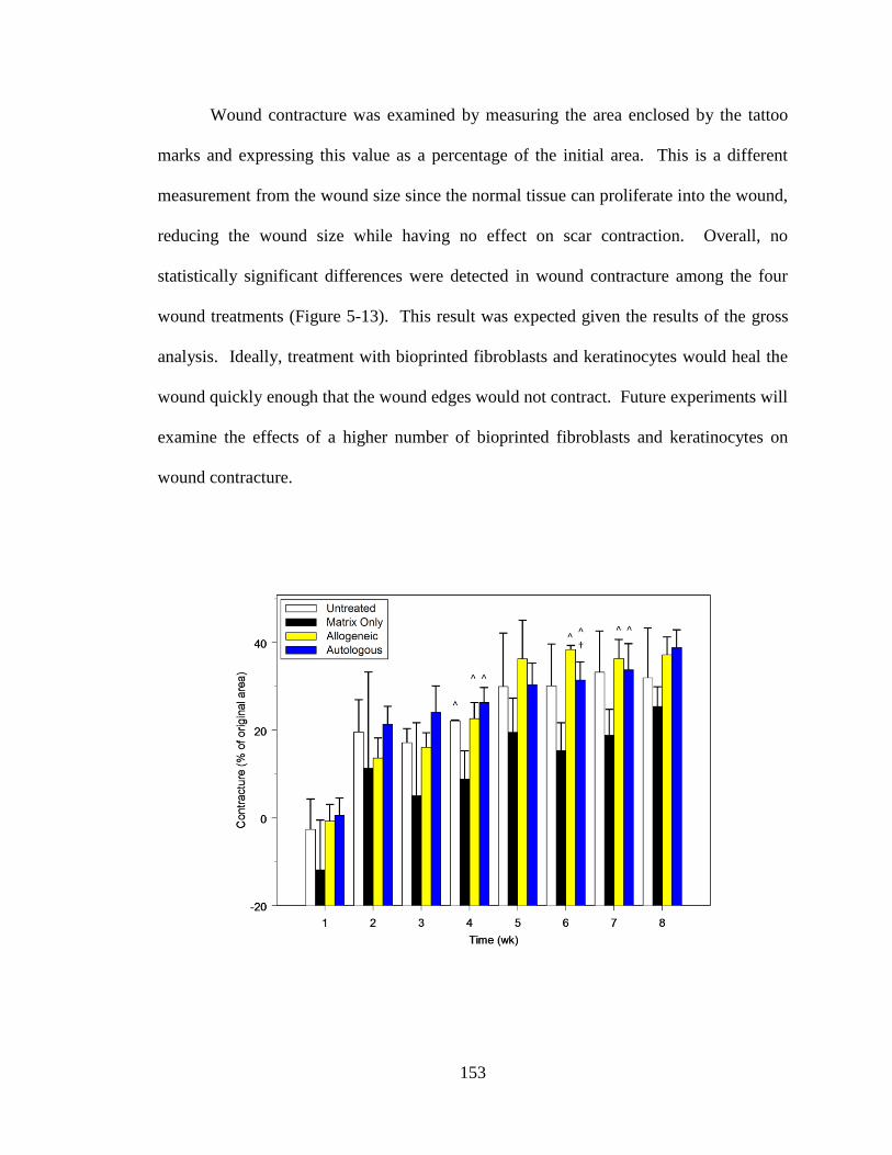
153
Wound contracture was examined by measuring the area enclosed by the tattoo
marks and expressing this value as a percentage of the initial area. This is a different
measurement from the wound size since the normal tissue can proliferate into the wound,
reducing the wound size while having no effect on scar contraction. Overall, no
statistically significant differences were detected in wound contracture among the four
wound treatments (Figure 5-13). This result was expected given the results of the gross
analysis. Ideally, treatment with bioprinted fibroblasts and keratinocytes would heal the
wound quickly enough that the wound edges would not contract. Future experiments will
examine the effects of a higher number of bioprinted fibroblasts and keratinocytes on
wound contracture.

154
In contrast to the wound size and contracture, wound epithelialization was
significantly higher when treated with bioprinted autologous fibroblasts and keratinocytes
(Figure 5-14). Epithelialization was examined by using ImageJ to measure the areas of
epithelial tissue visible on gross images including the epithelium from the advancing
wound edge. These results confirmed the gross analysis, showing that bioprinting skin
cells is a viable method of producing new skin for extensive wounds.
Figure 5-13. Analysis of wound contracture over 8 weeks. Wound contracture was measured by using
ImageJ software to evaluate the area encompassed by the wound tattoos compared to the initial area of 100
cm2. Data were analyzed by one-way ANOVA followed by Tukey's range test on statistically significant
ANOVA tests. Significance was defined as p < 0.05, n = 3. ^: significant versus fibrin/type I collagen
(matrix-only) negative control. †: significant versus allogeneic bioprinting treatment. Overall, treatment
with 10 million bioprinted fibroblasts and 10 million bioprinted keratinocytes did not significantly affect
wound contracture versus negative controls. This result was expected because the wound sizes were not
significantly different. Data presented as mean + standard deviation.

155
5.6.2.3. Histological Analysis
Histological samples taken from the centers of the wounds at 8 weeks showed
fully formed dermis and epidermis with the exception of the fibrin/type I collagen treated
wounds (Figure 5-15). These findings are consistent with the gross analysis (Figure 5-
11). Dermal papillae and rete ridges were visible, indicating that the bioprinted
fibroblasts and keratinocytes were able to produce the proper skin structure for this area
of the body.
Prelabeled autologous fibroblasts and keratinocytes were visible by fluorescence
analysis with DAPI counterstaining (Figure 5-16), indicating that the bioprinted skin cells
were responsible for the re-epithelialization seen on gross analysis. Allogeneic
keratinocytes were not visible although allogeneic fibroblasts could be seen. Again, this
finding is consistent with the gross results where the wound treated with allogeneic
fibroblasts and keratinocytes did not show statistically significant re-epithelialization
over negative controls. There are three possible explanations for this finding. First, the
Figure 5-14. Analysis of wound epithelialization over 8 weeks. Epithelialization was measured using
ImageJ software to evaluate areas of new epithelium formation including advancement of the wound edge.
These data are expressed as percentages of the total wound area. Data were analyzed by one-way ANOVA
followed by Tukey's range test on statistically significant ANOVA tests. Significance was defined as p <
0.05, n = 3. *: significant versus untreated negative control. ^: significant versus fibrin/type I collagen
(matrix-only) negative control. †: significant versus allogeneic bioprinting treatment. Overall, treatment
by bioprinting 10 million autologous and 10 million autologous keratinocytes demonstrated significantly
increased epithelialization over all other treatment groups. This result corroborates the gross analysis
showing areas of new epithelialization in the center of the wound. Data presented as mean + standard
deviation.

156
CM-DiI in the prelabeled allogeneic keratinocytes may have diluted to levels not visible
by fluorescence imaging due to cell division. This is unlikely considering the relative
lack of re-epithelialization and the visibility of prelabeled autologous keratinocytes.
Second, the number of bioprinted skin cells may have been too low to create skin from
allogeneic cells. Finally, cultures of keratinocytes may have been contaminated with
antigen-presenting cells (APCs) from the epidermis. Although allogeneic fibroblasts and
keratinocytes can be used to repair skin wounds, the presence of APCs would induce an
immune response to these cells. Fibroblasts are weakly immunogenic due to the lack of
CD28 ligand and would not be eliminated by the host immune response as quickly as the
keratinocytes. Lack of re-epithelialization with bioprinted allogeneic fibroblasts and
keratinocytes is likely due to a combination of too few cells and destruction of the cells
that were present. However, treatment with autologous skin cells was able to close the
wound with full re-epithelialization from bioprinted cells.
Figure 5-15. Hematoxylin and eosin evaluation of four
different wound treatments at 8 weeks. H&E stain of biopsies
taken from the wound center show the presence of fully formed
epithelial tissue in three of four treatments. The fibrin/type I
collagen treatment (matrix-only) did not show epithelium
formation, corroborating the gross analysis. Magnification: 50x.
Scale bar: 50 µm.

157
5.7. Conclusions
The goal of this aim was to create a skin bioprinter capable of repairing wounds in
a preclinical porcine model by using a scanning system to image the wound and bioprint
the missing skin cells. The skin bioprinter achieved most of the design goals we
established. It is a portable system capable of accommodating a wide range of body
types and can precisely deliver up to 8 different cell types in situ. The system can be
easily sterilized, used repeatedly, and is easy to maintain in working condition. However,
the imaging system did not perform to expectations during in vivo testing due to the
breathing motion of the patient. This issue will be corrected by replacing the laser
scanner with an imaging system that can take instantaneous snapshots of the wound and
create the wound map (Chapter 6).
Wounds repaired with autologous fibroblasts and keratinocytes demonstrated
increased epithelialization over all other treatments, although no statistically significant
Figure 5-16. Histological comparison of four different wound
treatments at 8 weeks. Histological sections were counterstained
with 4',6-diamidino-2-phenylindole (DAPI), a compound that
intercalates in DNA and fluoresces blue. Bioprinted fibroblasts
and keratinocytes were prelabeled with red fluorescent CM-DiI.
These prelabeled cells are visible in the center of the wound for the
autologous treatment. Only prelabeld fibroblasts are visible in the
allogeneic treatment. Magnification: 50x. Scale bar: 50 µm.

158
differences in wound size or contracture were detected. However, the power of this study
is too low to avoid type II errors. Prelabeled autologous fibroblasts and keratinocytes as
well as allogeneic fibroblasts were visible in the wound at 8 weeks, demonstrating that
bioprinted skin cells can survive, proliferate, and form skin tissue in an
immunocompetent large wound model. Although wounds were successfully repaired
with bioprinted skin cells, significant optimization is needed before in situ skin
bioprinting can be a viable technique for repair of human wounds. These optimizations
are discussed in Chapter 6.

159
References
Binder, K. W., Zhao, W., Dice, D., Tan, J., Kang, H. W., Atala, A., & Yoo, J. J. (2011).
Development of an in situ skin bioprinter for extensive burn wounds. Nat
Biotechnol.(Submitted).

160
CHAPTER 6
CONCLUSIONS AND FUTURE WORK
6.1. Introduction
This report has demonstrated that in situ skin bioprinting is a viable technique for
repair of full-thickness skin wounds. We developed a skin bioprinter capable of
delivering the contents of up to 8 different cartridges directly in a wound and showed that
fibroblasts and keratinocytes can be bioprinted in situ. These skin cells were able to
regenerate the dermis and epidermis in both a murine and porcine full-thickness
excisional wound model.
Based on our experience with in situ skin bioprinting in the porcine model, we
have determined that the original skin bioprinter design is not as effective as possible for
delivering large amounts of skin cells. The current device developed and tested in
Chapter 5 requires 20-30 minutes to bioprint one layer of skin cells at 100 cm2. Thus,
several hours will be required to repair the full depth of a full-thickness 100 cm2 wound.
This treatment time does not provide any advantage over cell spraying. Furthermore, the
current skin bioprinter requires mixing skin cells and hydrogels prior to bioprinting. This
process requires preparation time in a sterile cell culture field and presents significant
challenges for storing skin cells embedded in a hydrogel. In addition, even with
atomizing nozzles spraying cross-linker the skin bioprinter still has issues delivering cells
on curved surfaces. Finally, a new imaging system that does not have issues scanning the
surface of a breathing patient is needed to achieve our stated design goals.

161
6.2. Clinical Prototype
6.2.1. Hardware
The new design is based on vector dispensing instead of position dispensing.
Briefly, position dispensing is the current process which moves the printhead to a specific
point, delivers the cells, and moves to the next point. This process of moving and
Figure 6-1. Concept design of delivery system for the clinical skin bioprinter. (Left) Hydrogels and
cross-linkers are separate from the cartridges. They are now stored in large (1 liter) containers outside of
the cartridge. (Center) Cartridges are loaded into a motorized storage unit that locks a cartridge into a
connection with the hydrogel container. This storage unit is kept at 37°C. This unit can hold up to 20
different 10 mL cartridges. (Right) Two pumps (black) draw either hydrogel or cross-linker into nozzles
for bioprinting. A mixing chamber (blue) is mounted above one pump. This chamber draws the hydrogel
through the connected cartridge, ensuring that all contents in the cartridge are drawn into the chamber.
The mixed cells and hydrogel are then pumped through the nozzle for bioprinting. The two delivery pumps
operate simultaneously to deliver hydrogel and cross-linker at the same time. This provides more time for
the cross-linking reaction. This design overcomes the issues present in the preclinical prototype.

162
stopping at each specific point increases treatment time for a full-thickness wound. This
drawback to our current in situ skin bioprinting method was not apparent in our murine
model because the size of the wound on the mice was not large enough to show this flaw.
When scaled to the porcine model, this flaw became apparent even with the high
throughput printhead developed in Chapter 5.
Vector dispensing is an alternate delivery method that continuously delivers skin
cells and matrix instead of stopping to deliver the payload. The new delivery system will
turn on the delivery pumps when the printhead is over the wound and will deliver skin
cells in lines of varying widths across the wound. In this way we can leverage a much
higher movement speed in the motors achieving wound coverage at a rate of 5
cm/second/line. The resolution of the delivery system is dependent on the number of
lines to be bioprinted. We can deliver lines up to 0.5 - 1 cm wide for extremely fast
coverage; however, further testing is required to determine the full operating range of the
printhead.
Our current system and the system in the proposal are based on air pressure
driving the printhead. The new vector dispensing design does not use an outside pressure
source to drive the delivery system. Instead, the pressure is provided by internal pumps
that draw skin cells and matrix from cartridges inserted in the manifold. This new design
is self-contained and has a much smaller form factor than the preclinical prototype. Also,
in the new design the skin cells and matrix are in separate cartridges and are mixed in a
chamber prior to bioprinting. This allows us to package skin cells and matrix in separate
cartridges for easier storage. In addition, this new design allows mixing of skin cells and
various different matrices or growth factors at run-time in novel ways.
163
The cross-linker is its own cartridge and is sprayed on the hydrogel at the same
time that the skin cells are bioprinted. Delivering the hydrogel and cross-linker at the
same time will help bioprint skin cells on curved surfaces by providing more time for the
cross-linking reaction. The extra speed gained from vector dispensing will also enable
the clinical prototype to perform a pre-spray with cross-linker, allowing the cross-linking
reaction to begin as soon as the hydrogel impacts the wound surface. Furthermore, the
new design will incorporate a rotational motor and swivel on the delivery system to track
curved surfaces.
Due to the issues with the imaging system, we have evaluated the Kinect® system
from the Microsoft Corporation (Redmond, WA) for depth imaging. The Kinect is
$150/unit and provides infrared and visible light imaging at 30 frames/second. The form
factor is significantly smaller than any other imaging system we have evaluated in both
volume and mass. Open-source drivers have been developed for this system under the
GNU license. We are in the process of designing software based on the Kinect system
for integration into the skin bioprinter. This has several advantages over using the
commercial system used in the preclinical prototype. First, the application programming
interfaces are readily available and are written in accessible C++, unlike the NextEngine
system. Second, the speed of the scan is fast enough that the breathing of the patient will
not interfere with the scan. Finally, the Kinect data can be integrated directly in our
proprietary software. Commercial scanning systems require multiple conversion steps to
make the scanned data useable. The Kinect system is motorized so in the future we may
be able to use multiple systems to gather three-dimensional data very quickly for less
than a quarter of the price of a traditional 3D scanner.

164
6.2.2. Software
The software design for the clinical prototype follows a similar design to the
preclinical prototype (Figure 6-2). The major change to the software architecture is the
addition of a database holding the bioprinting parameters for materials loaded in the
cartridges. This library will provide a scripting language for parameters such as:
1. Type of matrix to use for a material
2. Density of material in a delivery volume
3. Acceptable resolution for each material
Figure 6-2. Clinical prototype software schematic. The software from the preclinical prototype
(Chapter 5) will be upgraded for clinical use. The major change for the clinical software is placement of
the bioprinting parameters in a separate database rather than maintaining this information in the Printhead
object. This library of parameters enables the addition of new cell types or biomaterials without needing to
hard-code parameters in the software. Adding a new cell type to the skin bioprinter would only require
adding an additional plugin to the library. This design will vastly increase the power of the skin bioprinter
as a method of incorporating new wound therapies as they become available.

165
4. How to bioprint each material
5. Acceptable combinations of materials
In the preclinical prototype this information was hard-coded in the software (Appendix
B). By encapsulating these parameters in a separate library, new cartridges can be added
without affecting the rest of the software. Combined with the updated hardware, the
clinical software will enable the skin bioprinter to become a powerful tool for
incorporating new wound therapies as they become available.
6.3. Analysis of Skin Bioprinting
6.3.1. Optimization of Bioprinting Parameters
There are two major parameters for printing cells: the delivery matrix and the cell
density. Our delivery method uses a mixture of fibrin and type I collagen because these
materials have already been used for delivery of skin cells. This matrix is biocompatible,
quickly degrades, and traps various growth factors as a fibrin clot would. However, the
mixture of fibrinogen and collagen has not been optimized for bioprinting fibroblasts and
keratinocytes. The proliferation of skin cells in various concentrations of fibrinogen and
collagen must be quantified to determine the best delivery matrix for fibroblasts and
keratinocytes. Furthermore, alternative hydrogels such as hyaluronic acid should be
examined as delivery vehicles for skin bioprinting due to their wound healing properties
(Chapter 1).
A detailed analysis of skin cell proliferation at various cell densities has not been
performed. A low number of cells may result in slow growth due to a lack of paracrine
signaling whereas a high number of cells can cause contact inhibition and reduced

166
growth. The effects of varying cell densities and matrices on cell proliferation will be
examined by using MTT proliferation assays. A single quantifiable outcome for cell
proliferation will provide a method to compare proliferation characteristics among
different cell densities and matrices.
A calibration curve for each cell type will be performed without delivery matrix
to establish baseline proliferation values. The calibration experiment will be performed
in a 96 well plate with one delivery volume of cells at varying cell numbers per volume.
After establishing baseline proliferation values, the proliferation effects of cell spacing
and number of cells per delivery volume will be quantified for each concentration of
delivery matrix. Each experiment will be performed in triplicate 96 well plates. The
delivery system can be programmed to deliver cells and MTT reagent in multiple plates
for a total of 288 samples. 96 well plates can hold 2 lines of cells at 2 mm spacing. 1
sample per plate will be used without cells to act as a negative control for the assay.
Proliferation data will be analyzed with a Matrix X Cell Density factorial analysis-of-
variance (ANOVA) test. Since pairwise comparisons will not be as useful in this context
as examinations of all statistically significant differences, Scheffé's test is more powerful
than Tukey's range test. The statistical power of the study will change based on the
number of matrices and cell densities tested. However, the ease at which the bioprinter
can be programmed to perform these assays enables more plates to be added if necessary.
If the treatments fail to show a significant difference in proliferation then more 96 well
plates can be added to increase the statistical power of the study. One potential pitfall in
this experiment is spectrophotometer interference from the matrix, which can block the

167
color emitted from formazan crystals. In that case, the matrix can be degraded just prior
to performing the MTT assay.
The combination of cell density and matrix that shows the highest proliferation
for any cell type will be used in subsequent experiments. These parameters will be stored
in the software parameter library for future use. Performing this analysis for each cell
type will provide crucial information about proper cell therapy for large wounds.
6.3.2. Global Gene Expression Analysis
Global gene expression profiles provide information about underlying
physiological mechanisms that may not be apparent from gross and histological analysis.
Global expression profiles have never been performed on bioprinted cells. By
performing this basic analysis, cellular changes as a result of bioprinting can be evaluated
and used as a guide for future experiments and therapies. Furthermore, a comprehensive
gene expression analysis comparing autologous and allogeneic wound repair has not been
performed. Thus, this analysis will provide essential information about the fundamental
cellular processes involved with in situ skin bioprinting.
Skin biopsies should be taken at 1, 2, 3, 4, 6, 8, 12, 16, 20, and 24 weeks. These
time points allow examination of critical healing pathways in the inflammatory,
proliferation, and remodeling phases of wound healing. Spacing the biopsies at later time
points will avoid repeated damage to the wound site by the biopsy process. Initial
identification of differentially expressed genes will be performed using one-way analysis
of variance with Student’s t-test and a false discovery rate of 0.05 using the Benjamini-
Hochberg correction. These genes will be examined in clusters and pathways and

168
referenced to corresponding human pathways. The four treatments – untreated, matrix-
only, allogeneic repair, and autologous repair – will be compared to identify specific
molecular pathways impacted by each treatment and also compared to normal skin. The
presence of skin cells in a wound will alter the healing process, ideally completely
covering the wound in less time than the negative controls take to heal. Although the
healing skin will be examined histologically, there may be subtle differences in activated
or repressed molecular pathways that would not be visible by histological examination.
Thus, analysis of global gene expression will reveal temporal shifts in gene expression.
The untreated group will demonstrate the native repair process and act as a
baseline control. Gene expression from the other treatments that is not significantly
different from the untreated wound can be attributed to the native repair process.
Measuring gene expression in the wound treated with fibrin/collagen will identify any
expression changes that are the result of the delivery matrix. By subtracting the gene
expression from these two negative controls, the specific healing pathways of allogeneic
and autologous fibroblasts and keratinocytes can be examined. Since the bioprinted
fibroblasts and keratinocytes will be creating skin tissue de novo, we expect to see a large
increase in expression of genes associated with the epidermal barrier, cell-cell adhesion
molecules, and extracellular matrix deposition including production of the stratum basale.
These expression profiles will be separated using hierarchical clustering based on
temporal and treatment factors. The clusters can then be subjected to enrichment analysis
to identify the biological processes associated with each cluster.
Allogeneic fibroblasts are already used in cell therapy for humans. However, to
the best of our knowledge the fundamental cellular processes underlying allogeneic cell

169
therapy in large wounds have never been studied. If the skin delivery system is to be
used without an autologous cell source then these fundamental processes must be
examined. Furthermore, subtle differences in allogeneic versus autologous repair can be
identified and used to develop novel therapies aimed at improving wound healing.
Therefore, this experiment will provide a wealth of basic information that will drive
future research in bioprinting skin.
6.3.3. Bioprinting Adnexal Structures In Situ
One of the major problems with current treatments for large wounds is the lack of
hair follicles and pigment (Chapter 1). Theoretically, the skin bioprinter has the
capability to overcome these problems by bioprinting hair follicles and melanocytes in a
skin construct. The anatomy of the hair follicle requires different reconstruction
techniques than fibroblasts, keratinocytes, or melanocytes. Cells within hair follicles are
not distributed evenly over a large area; rather, they are organized into discrete units with
relatively even distribution of units over a large area. Hypothetically, proper hair can be
generated for different body locations, age groups, and genders by bioprinting dermal
papilla cells at varying densities. Previous experiments have demonstrated that hair shaft
thickness and length is in part determined by dermal papilla cell number and volume,
with hairs becoming longer with increasing cell number (Elliott et al., 1999). This
experiment will examine hair formation both macroscopically and microscopically to
determine how changing the density of dermal papilla cells affects both the formation of
follicles and the speed of hair growth. The precise bioprinting capabilities of the skin
delivery system offer a unique opportunity to determine how seeding of dermal papilla

170
cells affects the number of follicles produced. By printing the cells in units in a specified
pattern across the full-thickness skin defect, the ability of cells to form multiple follicles
can be determined. For example, if a single unit of dermal papilla cells is printed at 5
mm intervals and one hair follicle is observed at the location of the unit, then the cells
organized into a single functioning unit. However, if multiple follicles are observed, then
the printed cells organized into multiple functioning units. This experiment therefore will
determine both the functional capabilities of printed dermal papilla cells and their ability
to form multiple hair follicles. This is an important result because matching normal skin
requires the correct number of hairs in addition to the correct type of hair. If the cells
organize into multiple follicles then the seeding density must be adjusted to accommodate
the proper location on the body.
Unlike hair follicles, melanocytes are present in a relatively even distribution
across the epidermis, in a ratio of 10 to 40 keratinocytes per melanocyte. In this case, cell
distribution is more accurately measured as cells per square centimeter. We hypothesize
that bioprinting melanocytes in varying densities can regenerate proper pigmentation for
a variety of skin colors, as demonstrated by seeding of cultured skin substitutes with
melanocytes (Swope et al., 2002).
The skin bioprinter can extend wound therapy beyond hair follicles and pigment.
It is possible that the blood vessels, nerves, and glands present in normal skin could be
regenerated by incorporating cartridges of stem cells. By providing a delivery method for
virtually any possible cell type, the skin bioprinter can assimilate new wound
technologies as they become available.

171
6.4. Final Conclusions
The cartridge-based design of the skin bioprinter enables virtually any cell type,
macromolecule, or biomaterial to be bioprinted directly in a wound. Possible
experiments employing this technology are virtually limitless, extending from scarless
healing reagents to growth factors to stem cells. We have demonstrated in this
dissertation that in situ bioprinting of fibroblasts and keratinocytes is a viable method of
generating dermis and epidermis in full-thickness skin wounds. If we can create
functional skin using multiple cell types then our technology could be used not only for
repair of large wounds but also for regeneration of old wounds that already have scars.
Therefore, in situ skin bioprinting is a valuable addition to the armamentarium combating
large wounds.

172
References
Elliott, K., Stephenson, T. J., & Messenger, A. G. (1999). Differences in hair follicle
dermal papilla volume are due to extracellular matrix volume and cell number:
implications for the control of hair follicle size and androgen responses. J Invest
Dermatol., 113, 873-877.
Swope, V. B., Supp, A. P., & Boyce, S. T. (2002). Regulation of cutaneous pigmentation
by titration of human melanocytes in cultured skin substitutes grafted to athymic
mice. Wound.Repair Regen., 10, 378-386.

173
APPENDIX A
BIOPRINTER V2.0 SOFTWARE
A.1. MAIN
using namespace Bioprinter;
[STAThreadAttribute]
int main(array<System::String ^> ^args)
{
// Enabling Windows XP visual effects before any controls are created
Application::EnableVisualStyles();
Application::SetCompatibleTextRenderingDefault(false);
// Create the three main components
Interface ^ui = gcnew Interface();
Logic ^logic = gcnew Logic();
Database ^database = gcnew Database();
// Link the components
ui->SetLogic(logic);
logic->SetInterface(ui);
logic->SetDatabase(database);

174
database->SetLogic(logic);
// Create the main window and run it
Application::Run(ui);
delete ui;
delete logic;
delete database;
return 0;
}

175
A.2. INTERFACE_LOAD
// Load the default configuration into memory
ArrayList ^configuration = gcnew ArrayList();
m_logic->OpenConfiguration(Environment::CurrentDirectory
+ "\\Default Configuration.biocfg", configuration);
if (configuration->Count > 0)
{
this->m_configurationform->LoadConfiguration(configuration);
}
else
{
::MessageBox::Show("Default configuration is invalid.", "Bioprinter: Error");
}
delete configuration;

176
A.3. INTERFACE_OPEN IMAGE
if (this->OpenFileDialog->ShowDialog() ==
System::Windows::Forms::DialogResult::OK)
{
try
{
if (m_layer >= 0 && m_picturemap)
{
if (::MessageBox::Show("Do you want to add an additional layer to the
printed object?", "Bioprinter", ::MessageBoxButtons::YesNo) ==
::DialogResult::Yes)
{
m_layer++;
}
}
if (m_picturemap) delete m_picturemap;
this->PictureBox->Image = Drawing::Image::FromFile(
this->OpenFileDialog->FileName);
// A Bitmap is required to get the pixel data
m_picturemap = gcnew Bitmap(this->PictureBox->Image);
// Clear the memory so everything can be reset
m_useedges = false;

177
m_definingedges = false;
m_gridrows = -1;
m_gridcolumns = -1;
m_numberofrows = 1;
m_numberofcolumns = 1;
for (int i = 0; i < m_rowgrid->Count; i++)
{
Line ^line = safe_cast<Line ^> (m_rowgrid[i]);
if (line->point1) delete line->point1;
if (line->point2) delete line->point2;
if (line->point3) delete line->point3;
if (line->point4) delete line->point4;
}
m_rowgrid->Clear();
for (int i = 0; i < m_columngrid->Count; i++)
{
Line ^line = safe_cast<Line ^> (m_columngrid[i]);
if (line->point1) delete line->point1;
if (line->point2) delete line->point2;
if (line->point3) delete line->point3;
if (line->point4) delete line->point4;
}
m_columngrid->Clear();

178
m_rowedges->Clear();
m_columnedges->Clear();
// Set the PictureBox size
this->PictureBox->Size = this->PictureBox->Image->Size;
}
catch (OutOfMemoryException ^)
{
System::Windows::Forms::MessageBox::Show("Invalid image file.",
"Bioprinter: Error");
}
}

179
A.4. INTERFACE_PARSE IMAGE
try
{
// Quick test to see if an image is open
if (!m_picturemap)
{
throw gcnew System::NullReferenceException;
}
if (System::Windows::Forms::MessageBox::Show("Do you wish to parse the image?",
"Bioprinter", MessageBoxButtons::YesNo) == ::DialogResult::Yes)
{
double pixeldistance = 1;
double centimeterdistance = 1;
double dropspacingdouble = 1;
// Get the parse image options
if (m_parseimageform->ShowDialog() == ::DialogResult::OK)
{
pixeldistance = m_parseimageform->PixelDistance;
centimeterdistance = m_parseimageform->CentimeterDistance;
dropspacingdouble = m_parseimageform->DropSpacing;
m_logic->SetCentimeterDistance(centimeterdistance);
m_logic->SetPixelDistance(pixeldistance);

180
}
// Convert the drop spacing to pixels using pixeldistance and centimeterdistance
// and subtract because the the picture starts from pixel 0
int dropspacing = Convert::ToInt32(System::Math::Ceiling(
(pixeldistance * dropspacingdouble)) / centimeterdistance);
if (dropspacing == 0)
{
dropspacing = 1;
}
// Update the status
this->ChangeStatus("Parsing image...");
// Force a redraw of the form
this->Refresh();
System::Drawing::Color ^pixelcolor;
String ^points = gcnew String("");
ArrayList ^allpoints = gcnew ArrayList();
this->ProgressBar->Visible = true;
// First check to see if the user defined their own edges. If they did
// not, then use the edges of the picture as the edges for the grid.
if (!m_useedges && m_rowedges->Count == 0 &&
m_columnedges->Count == 0)

181
{
this->ProgressBar->Maximum = this->PictureBox->Size.Width;
// If the user did not define a grid then we need to make a simple grid
if ((m_rowgrid->Count == 0) && (m_columngrid->Count == 0))
{
// Process the image and create a string for each row of points.
// Add this string to an ArrayList for large pictures.
int i = 0;
for (i; i < PictureBox->Size.Width; i += dropspacing)
{
int j = 0;
for (j; j < PictureBox->Size.Height; j += dropspacing)
{
pixelcolor = m_picturemap->GetPixel(i,j);
if (!(pixelcolor->R <= 1 && pixelcolor->B <= 1
&& pixelcolor->G <= 1))
{
points += "(" + i.ToString() + "," + j.ToString() + ")@0#" +
(pixelcolor->R + pixelcolor->B + pixelcolor->G).ToString();
}
}
// Check the edge in case we missed it
182
if (j - dropspacing < PictureBox->Size.Height - 1)
{
pixelcolor = m_picturemap->GetPixel(i,PictureBox->Size.Height - 1);
if (!(pixelcolor->R <= 1 && pixelcolor->B <= 1
&& pixelcolor->G <= 1))
{
points += "(" + i.ToString() + "," + j.ToString() + ")@0#" +
(pixelcolor->R + pixelcolor->B + pixelcolor->G).ToString();
}
}
if (points != "")
{
allpoints->Add(points);
}
points = "";
this->ProgressBar->Increment(1);
}
// Check the last row in case we missed it
if (i - dropspacing < PictureBox->Size.Width - 1)
{
int j = 0;

183
for (j; j < PictureBox->Size.Height; j += dropspacing)
{
pixelcolor = m_picturemap->GetPixel(PictureBox->Size.Width-1,j);
if (!(pixelcolor->R <= 1 && pixelcolor->B <= 1
&& pixelcolor->G <= 1))
{
points += "(" + (PictureBox->Size.Width-1).ToString() + "," +
j.ToString() + ")@0#" + (pixelcolor->R + pixelcolor->B +
pixelcolor->G).ToString();
}
}
// Check the edge in case we missed it
if (j - dropspacing < PictureBox->Size.Height - 1)
{
pixelcolor = m_picturemap->GetPixel(PictureBox->Size.Width-
1,PictureBox->Size.Height - 1);
if (!(pixelcolor->R <= 1 && pixelcolor->B <= 1
&& pixelcolor->G <= 1))
{
points += "(" + (PictureBox->Size.Width-1).ToString() + "," +
j.ToString() + ")@0#" + (pixelcolor->R + pixelcolor->B +
pixelcolor->G).ToString();

184
}
}
if (points != "")
{
allpoints->Add(points);
}
points = "";
this->ProgressBar->Increment(1);
}
m_logic->SimpleGrid(m_layer, allpoints);
}
// The user defined a grid but no edges (thus, the entire picture has a grid).
// Here we need to use the grid to fill in the appropriate points
else
{
this->ProgressBar->Maximum = (m_rowgrid->Count-1) *
(m_columngrid->Count-1);
// First create the organ object
ArrayList ^rowscolumns = gcnew ArrayList();

185
// Subtract 1 from the row count to account for the top edge
for (int i = 0; i < m_rowgrid->Count - 1; i++)
{
// Subtract 1 from the column count for the left edge
rowscolumns->Add(m_columngrid->Count - 1);
}
m_logic->CreateGrid(m_layer, rowscolumns);
delete rowscolumns;
// Now parse the image. The top and left corners of each grid
// mark the beginning of a new set of points. This ensures that
// every point is covered except for the bottom and right edge
// which are covered in a special case.
// Holds the current row
Line ^row = safe_cast<Line ^> (m_rowgrid[1]);
// Holds the current column
Line ^column = safe_cast<Line ^> (m_columngrid[1]);
int i = 0;
int j = 0;
int lasti = 0;
int lastj = 0;
186
int rowpos = 1; // Holds the position in the row grid, must start at
// the second line (since the first is the left edge of the picture)
int columnpos = 1; // Holds the position in the column grid
// Process the image and create a string for each row of points.
// Add this string to an ArrayList for large pictures.
while (rowpos < m_rowgrid->Count)
{
for (columnpos; columnpos < m_columngrid->Count; columnpos++)
{
column = safe_cast<Line ^> (m_columngrid[columnpos]);
while(j < row->point2->Y)
{
while (i < column->point2->X)
{
pixelcolor = m_picturemap->GetPixel(i,j);
if (!(pixelcolor->R <= 1 && pixelcolor->B <= 1
&& pixelcolor ->G <= 1))
{
points += "(" + i.ToString() + "," +
j.ToString() + ")@0#" + (pixelcolor->R +
pixelcolor->B + pixelcolor->G).ToString();
}
i += dropspacing;

187
}
allpoints->Add(points);
points = "";
i = lasti;
j += dropspacing;
}
lasti = column->point2->X;
i = lasti;
// Call down to the Logic object to add the points
m_logic->Grid(m_layer, rowpos - 1, columnpos - 1, allpoints);
this->ProgressBar->Increment(1);
j = lastj;
points = "";
allpoints->Clear();
}
lastj = row->point2->Y;
rowpos++;
if (rowpos < m_rowgrid->Count)

188
{
row = safe_cast<Line ^> (m_rowgrid[rowpos]);
}
columnpos = 1;
column = safe_cast<Line ^> (m_columngrid[columnpos]);
points = "";
allpoints->Clear();
}
}
}
// The user defined edges. We need to use them to parse the image
else
{
// The user defined edges but not a grid. Here we need to use
// the edges but not apply a grid to the whole picture. This is almost
// the same as the case with just a grid except the row and
// column starting positions will need to be at the edges.
if ((m_rowgrid->Count == 0) && (m_columngrid->Count == 0))
{

189
::Drawing::Point ^firstpoint = safe_cast<::Drawing::Point ^>
(m_rowedges[0]);
::Drawing::Point ^secondpoint = safe_cast<::Drawing::Point ^>
(m_rowedges[1]);
this->ProgressBar->Maximum = safe_cast<::Drawing::Point ^>
(m_rowedges[m_rowedges->Count-1])->Y - firstpoint->Y;
int i = 0;
int j = dropspacing - 2*dropspacing;
// Traverse the edges by rows
for (int k = 1; k < m_rowedges->Count; k++)
{
firstpoint = safe_cast<::Drawing::Point ^> (m_rowedges[k-1]);
secondpoint = safe_cast<::Drawing::Point ^> (m_rowedges[k]);
// Make sure we're obeying the drop spacing
while ((j + dropspacing > firstpoint->Y)
&& (k < m_rowedges->Count-1))
{
k++;
firstpoint = safe_cast<::Drawing::Point ^>
(m_rowedges[k-1]);

190
secondpoint = safe_cast<::Drawing::Point ^>
(m_rowedges[k]);
}
if (k == m_rowedges->Count-1)
{
break;
}
// Check for duplicate points and skip them
while ((firstpoint->X == secondpoint->X)
&& (firstpoint->Y == secondpoint->Y))
{
k++;
firstpoint = safe_cast<::Drawing::Point ^>
(m_rowedges[k-1]);
secondpoint = safe_cast<::Drawing::Point ^>
(m_rowedges[k]);
}
i = firstpoint->X;
j = firstpoint->Y;
// Make sure we only connect points on one row

191
if (j == secondpoint->Y)
{
while (i <= secondpoint->X)
{
pixelcolor = m_picturemap->GetPixel(i,j);
if (!(pixelcolor->R <= 1 && pixelcolor->B
<= 1 && pixelcolor->G <= 1))
{
points += "(" + i.ToString() + "," +
j.ToString() + ")@0#" + (pixelcolor
->R + pixelcolor->B + pixelcolor
->G).ToString();
}
i += dropspacing;
}
// Make sure we don't add double points at the
// beginning of rows.
// This occurs when two edge points are next to
// each other at the beginning of a row.
if (allpoints->Count > 0)
{

192
if (points != "" && safe_cast<String ^>
(allpoints[allpoints->Count - 1]) != "")
{
if (points->Substring(0, points->IndexOf(")") + 1)
== safe_cast<String ^> (allpoints[allpoints-
>Count - 1])->Substring(0, points-
>IndexOf(")") + 1))
{
try
{
points = points->Remove(0, points-
>IndexOf("(", points->IndexOf(")")));
}
catch (System::ArgumentOutOfRangeException^)
{
points = "";
}
}
}
}
allpoints->Add(points);
points = "";

193
this->ProgressBar->Increment(1);
}
}
m_logic->SimpleGrid(m_layer, allpoints);
}
// The user defined a grid and edges. This is the most complicated case, where the edges
// of the grid need to correspond to the user's defined edges, not the edges of the graph.
else
{
// First create the organ object
ArrayList ^rowscolumns = gcnew ArrayList();
Line ^row;
Line ^column;
int numcolumns = 0;
int i = 0;
for (i; i < m_rowgrid->Count; i++)
{
row = safe_cast<Line ^> (m_rowgrid[i]);
for (int j = 0; j < m_columngrid->Count; j++)
{

194
column = safe_cast<Line ^> (m_columngrid[j]);
// Traverse the columns and add 1 for every grid
if (column->point1->X <= row->point4->X)
{
// Account for blank space in a column
if (j <= m_columngrid->Count - 2)
{
if (column->point1->X != safe_cast<Line ^>
(m_columngrid[j+1])->point1->X)
{
numcolumns++;
}
}
else
{
if (column->point1->X == safe_cast<Line ^>
(m_columngrid[j-1])->point1->X)
{
numcolumns++;
}
}
}
}

195
// If there is blank space on a row make sure we don't add twice the
// number of rows
if (i <= m_rowgrid->Count - 2)
{
if (row->point1->Y != safe_cast<Line ^> (m_rowgrid[i+1])->point1->Y)
{
// Add one for the edge
//numcolumns++;
rowscolumns->Add(numcolumns);
numcolumns = 0;
}
// Make sure we don't add twice the number of columns
if (row->point1->Y == safe_cast<Line ^> (m_rowgrid[i+1])->point1->Y)
{
numcolumns = 0;
}
}
// Check if the last row has already been added. If not, add the new number of
// grids.
else
{

196
if (row->point1->Y == safe_cast<Line ^> (m_rowgrid[i-1])->point1->Y)
{
// Add one for the edge
//numcolumns++;
rowscolumns->Add(numcolumns);
numcolumns = 0;
}
}
}
m_logic->CreateGrid(m_layer, rowscolumns);
this->ProgressBar->Maximum = (rowscolumns->Count * safe_cast<int>
(rowscolumns[0]));
// Now parse the image. The top and left corners of each grid
// mark the beginning of a new set of points. This ensures that
// every point is covered except for the bottom and right edge
// which are covered in a special case.
row = safe_cast<Line ^> (m_rowgrid[0]); // Holds the current row
int rowpos = 0; // Holds the position in the row grid, must start at the second line (since
// the first is the left edge of the picture)
// Make sure we go to the second row to avoid the top edge

197
int k = 0;
for (k; k < m_rowgrid->Count; k++)
{
if (row->point1->Y != safe_cast<Line ^> (m_rowgrid[k])->point1->Y)
{
break;
}
}
row = safe_cast<Line ^> (m_rowgrid[k]);
rowpos = k;
column = safe_cast<Line ^> (m_columngrid[0]); // Holds the current column
int columnpos = 0; // Holds the position in the column grid
// Make sure we go to the second row to avoid the left edge
int t = 0;
for (t; t < m_columngrid->Count; t++)
{
if (column->point1->X != safe_cast<Line ^> (m_columngrid[t])->point1->X)
{
break;
}
}
column = safe_cast<Line ^> (m_columngrid[t]);
columnpos = t;

198
i = safe_cast<Line ^> (m_columngrid[0])->point1->X;
int j = safe_cast<Line ^> (m_rowgrid[0])->point1->Y;
int lasti = safe_cast<Line ^> (m_columngrid[0])->point1->X;
int lastj = safe_cast<Line ^> (m_rowgrid[0])->point1->Y;
int rowcolumnposrow = 0;
int rowcolumnposcolumn = 0;
// Start processing the image and create a string for each row of points.
// Add this string to an ArrayList to save on space for large pictures.
while (rowcolumnposrow < rowscolumns->Count)
{
while (rowcolumnposcolumn<safe_cast<int>(rowscolumns[rowcolumnposrow]))
{
if (columnpos < m_columngrid->Count)
{
column = safe_cast<Line ^> (m_columngrid[columnpos]);
}
while (j < row->point2->Y)
{
while (i < column->point2->X)
{
pixelcolor = m_picturemap->GetPixel(i,j);
199
if (!(pixelcolor->R <= 1 && pixelcolor->B <= 1 &&
pixelcolor->G <= 1))
{
points += "(" + i.ToString() + "," + j.ToString() +
")@0#" + (pixelcolor->R + pixelcolor->B +
pixelcolor->G).ToString();
}
i += dropspacing;
}
allpoints->Add(points);
points = "";
i = lasti;
j += dropspacing;
}
// Account for blank space on a column or multiple columns on a single X
if (columnpos <= m_columngrid->Count - 2)
{
if (column->point1->X != safe_cast<Line ^>
(m_columngrid[columnpos+1])->point1->X)
{
columnpos++;
200
}
else
{
for (columnpos; columnpos < m_columngrid->Count;
columnpos++)
{
if (column->point1->X != safe_cast<Line ^>
(m_columngrid[columnpos])->point1->X)
{
break;
}
}
}
}
lasti = column->point2->X;
i = lasti;
// Call down to the Logic object to add the points
m_logic->Grid(m_layer, rowcolumnposrow, rowcolumnposcolumn, allpoints);
this->ProgressBar->Increment(1);
j = lastj;
points = "";

201
allpoints->Clear();
rowcolumnposcolumn++;
if (rowcolumnposcolumn == 9 && rowcolumnposrow == 2)
{
int q = 0;
}
}
lastj = safe_cast<Line ^> (m_rowgrid[rowpos])->point2->Y;
j = lastj;
// If there is blank space on a row make sure we don't only count half the number of rows
if (rowpos <= m_rowgrid->Count - 2)
{
if (row->point1->Y != safe_cast<Line ^> (m_rowgrid[rowpos+1])->point1->Y)
{
rowpos++;
}
else
{
for (rowpos; rowpos < m_rowgrid->Count; rowpos++)
{
if (row->point1->Y != safe_cast<Line ^> (m_rowgrid[rowpos])-
>point1->Y)

202
{
break;
}
}
}
}
if (rowpos < m_rowgrid->Count)
{
row = safe_cast<Line ^> (m_rowgrid[rowpos]);
}
i = safe_cast<Line ^> (m_columngrid[0])->point1->X;
columnpos = t;
column = safe_cast<Line ^> (m_columngrid[columnpos]);
points = "";
allpoints->Clear();
rowcolumnposrow++;
rowcolumnposcolumn = 0;
}
delete rowscolumns;

203
}
}
delete points;
delete allpoints;
this->ProgressBar->Value = this->ProgressBar->Minimum;
this->ProgressBar->Visible = false;
this->ChangeStatus("");
}
}
catch (System::NullReferenceException ^)
{
this->ProgressBar->Value = this->ProgressBar->Minimum;
this->ProgressBar->Visible = false;
::MessageBox::Show("Please open an image before parsing.", "Bioprinter:
Error");
}

204
A.5. INTERFACE_DEFINE GRID
try
{
// Quick test to see if there's an open image file
// Throws System::NullReferenceException if no file is open
if (!m_picturemap)
{
throw gcnew System::NullReferenceException;
}
this->m_definegridform->ResetForm();
if (this->m_definegridform->ShowDialog(this) ==
System::Windows::Forms::DialogResult::OK)
{
m_gridrows = Convert::ToUInt32(m_definegridform->GetRows());
m_gridcolumns = Convert::ToUInt32(m_definegridform->GetColumns());
m_useedges = m_definegridform->GetEdges();
if (m_gridrows == 0)
{
m_rowgrid->Clear();
}
if (m_gridcolumns == 0)

205
{
m_columngrid->Clear();
}
if (m_gridrows > this->PictureBox->Image->Height)
{
::MessageBox::Show("Row size too large. Setting row size to picture
height.", "Bioprinter: Error");
}
if (m_gridcolumns > this->PictureBox->Image->Width)
{
::MessageBox::Show("Columns size too large. Setting column size to
picture width.", "Bioprinter: Error");
}
if (m_useedges == true && m_rowedges->Count == 0 && m_columnedges-
>Count == 0)
{
::MessageBox::Show("No edges defined. Using picture edges to define
the grid.", "Bioprinter: Error");
m_useedges = false;
}

206
this->DefineGrid();
}
}
catch (System::NullReferenceException ^)
{
::MessageBox::Show("Please open a valid image file before defining grid.",
"Bioprinter: Error");
}
catch (Exception ^e)
{
this->ReportError(e->Message);
}

207
A.6. INTERFACE_DEFINE EDGES
// Start the image processing toolbox
try
{
// Quick test to see if the PictureBox actually has an image, will throw
System::NullReferenceException if there is no image.
if (!m_picturemap)
{
throw gcnew System::NullReferenceException;
}
if (::MessageBox::Show("Do you want to run the image processing toolbox?",
"Bioprinter", ::MessageBoxButtons::YesNo) == ::DialogResult::Yes)
{
this->ImageProcessingProcess->Start(String::Concat(m_filepath, "\\Image
Processing\\iplab.exe"));
}
// Use the edge image to create a new bitmap for edge parsing
if (this->OpenFileDialog->ShowDialog() == ::DialogResult::OK)
{
// Update the program status
this->ChangeStatus("Defining edges...");
// Force a redraw of the form

208
this->Refresh();
// Create the new bitmap
::Drawing::Bitmap ^edgemap = gcnew Bitmap(::Image::FromFile(this-
>OpenFileDialog->FileName));
// Make sure the picture edges line up. If not, the algorithm will crash.
if ((edgemap->Width != m_picturemap->Width) || (edgemap->Height !=
m_picturemap->Height))
{
delete edgemap;
throw gcnew System::OutOfMemoryException;
}
System::Drawing::Color ^pixelcolor;
System::Drawing::Color ^realpicturecolor;
bool rowfirstpoint = false;
bool columnfirstpoint = false;
// Parse the edge map and place the edge points into the member m_edges
// This is done by ignoring any black space on the left of the first non-black
// pixel on any row. On that same row, the algorithm ignores all pixels until it
// reaches the next black pixel or the image edge. The pixel directly before the
// black pixel is the next part of the edge.
209
this->ProgressBar->Maximum = 2*(edgemap->Size.Height * edgemap-
>Size.Width);
this->ProgressBar->Visible = true;
// Check the rows
for (int i = 0; i < edgemap->Size.Height; i++)
{
for (int j = 0; j < edgemap->Size.Width; j++)
{
pixelcolor = edgemap->GetPixel(j,i);
realpicturecolor = m_picturemap->GetPixel(j,i);
if (!(pixelcolor->R <= 1 && pixelcolor->B <= 1 && pixelcolor-
>G <= 1) && !rowfirstpoint)
{
// Make sure this point isn't black on the actual picture
if (!(realpicturecolor->R <= 1 && realpicturecolor->B <=
1 && realpicturecolor->G <= 1))
{
// Make sure we don't add duplicates
if (m_rowedges->Count > 0)
{
if (!((i == safe_cast<::Point ^>
(m_rowedges[m_rowedges->Count-1])->X) &&
210
j == safe_cast<::Point ^>
(m_rowedges[m_rowedges->Count-1])->Y))
{
m_rowedges>Add(gcnew::Drawing::Point(j,i));
rowfirstpoint = true;
}
}
else
{
m_rowedges->Add(gcnew ::Drawing::Point(j,i));
rowfirstpoint = true;
}
}
}
// One point has been found on the row so skip everything until the next black point
if ((pixelcolor->R <= 1 && pixelcolor->B <= 1 && pixelcolor->G <= 1) &&
rowfirstpoint)
{
// Check to make sure this point isn't white on the actual picture.
// If it is, then this isn't a true edge point.
if (realpicturecolor->R <= 1 && realpicturecolor->B <= 1 && realpicturecolor-
>G <= 1)

211
{
// Make sure we don't add duplicates
if (m_rowedges->Count > 0)
{
if (!((i == safe_cast<::Point ^> (m_rowedges[m_rowedges-
>Count-1])->X) && j == safe_cast<::Point ^>
(m_rowedges[m_rowedges->Count-1])->Y))
{
m_rowedges->Add(gcnew ::Drawing::Point(j-1,i));
}
}
else
{
m_rowedges->Add(gcnew ::Drawing::Point(j-1,i));
}
// We found another point so update rowfirstpoint
rowfirstpoint = false;
}
}
// Check the right edge

212
if (((!(pixelcolor->R <= 1 && pixelcolor->B <= 1 && pixelcolor->G <= 1) &&
!rowfirstpoint) || ((pixelcolor->R <= 1 && pixelcolor->B <= 1 && pixelcolor->G
<= 1) && rowfirstpoint)) && j == edgemap->Size.Width -1)
{
// Make sure we don't add duplicates
if (m_rowedges->Count > 0)
{
if (!((i == safe_cast<::Point ^> (m_rowedges[m_rowedges->Count-1])-
>X) && j == safe_cast<::Point ^> (m_rowedges[m_rowedges-
>Count-1])->Y))
{
m_rowedges->Add(gcnew ::Drawing::Point(j,i));
}
}
else
{
m_rowedges->Add(gcnew ::Drawing::Point(j,i));
}
}
this->ProgressBar->Increment(1);
}

213
rowfirstpoint = false;
}
// Check the columns
for (int i = 0; i < edgemap->Size.Width; i++)
{
for (int j = 0; j < edgemap->Size.Height; j++)
{
pixelcolor = edgemap->GetPixel(i,j);
realpicturecolor = m_picturemap->GetPixel(i,j);
if (!(pixelcolor->R <= 1 && pixelcolor->B <= 1 && pixelcolor->G <= 1)
&& !columnfirstpoint)
{
// Make sure this pixel isn't black on the actual picture
if (!(realpicturecolor->R <= 1 && realpicturecolor->B <= 1 &&
realpicturecolor->G <= 1))
{
// Make sure we don't add duplicates
if (m_columnedges->Count > 0)
{
if (!((i == safe_cast<::Point ^>
(m_columnedges[m_columnedges->Count-1])->X)

214
&& j == safe_cast<::Point ^>
(m_columnedges[m_columnedges->Count-1])->Y))
{
m_columnedges->Add(gcnew ::Drawing::Point(i,j));
columnfirstpoint = true;
}
}
else
{
m_columnedges->Add(gcnew ::Drawing::Point(i,j));
columnfirstpoint = true;
}
}
}
// One point has been found on the column so skip everything until the next black point
else if ((pixelcolor->R <= 1 && pixelcolor->B <= 1 && pixelcolor->G <= 1) &&
columnfirstpoint)
{
// Check to make sure this point isn't white on the actual picture.
// If it is, then this isn't a true edge point.
if (realpicturecolor->R <= 1 && realpicturecolor->B <= 1 && realpicturecolor-
>G <= 1)

215
{
// Make sure we don't add duplicates
if (m_columnedges->Count > 0)
{
if (!((i == safe_cast<::Point ^> (m_columnedges[m_columnedges-
>Count-1])->X) && j == safe_cast<::Point ^>
(m_columnedges[m_columnedges->Count-1])->Y))
{
m_columnedges->Add(gcnew ::Drawing::Point(i,j-1));
}
}
else
{
m_columnedges->Add(gcnew ::Drawing::Point(i,j-1));
}
// We did find another point so update columnfirstpoint
columnfirstpoint = false;
}
}
// Check the bottom edge
if (((!(pixelcolor->R <= 1 && pixelcolor->B <= 1 && pixelcolor->G <= 1) &&
!columnfirstpoint) || ((pixelcolor->R <= 1 && pixelcolor->B <= 1 &&

216
pixelcolor->G <= 1) && columnfirstpoint)) && j == edgemap-
>Size.Height-1)
{
// Make sure we don't add duplicates
if (m_columnedges->Count > 0)
{
if (!((i == safe_cast<::Point ^> (m_columnedges[m_columnedges-
>Count-1])->X) && j == safe_cast<::Point ^>
(m_columnedges[m_columnedges->Count-1])->Y))
{
m_columnedges->Add(gcnew ::Drawing::Point(i,j));
}
}
else
{
m_columnedges->Add(gcnew ::Drawing::Point(i,j));
}
}
this->ProgressBar->Increment(1);
}
columnfirstpoint = false;
}

217
this->ProgressBar->Visible = false;
this->ProgressBar->Value = this->ProgressBar->Minimum;
this->ChangeStatus("");
delete edgemap;
// Force a redraw of the picture
this->PictureBox->Refresh();
}
}
catch (System::OutOfMemoryException ^)
{
::MessageBox::Show("Invalid image file or image dimensions do not match
current image.", "Bioprinter: Error");
}
catch (System::NullReferenceException ^)
{
::MessageBox::Show("Please open an image before attempting to define edges.",
"Bioprinter: Error");
}
catch (Exception ^e)
{
this->ReportError(e->Message);
}

218
A.7. INTERFACE_PRINT
// Quick test to see if an image is open
bool exception = false;
try
{
if (!m_picturemap)
{
throw gcnew System::NullReferenceException;
}
}
catch (System::NullReferenceException^)
{
exception = true;
::MessageBox::Show("Please open an image before printing.", "Bioprinter: Error");
}
if (!exception)
{
if (::MessageBox::Show("Are you sure you want to print the image?", "Bioprinter",
::MessageBoxButtons::YesNo) == ::DialogResult::Yes)
{
if (::MessageBox::Show("Is the current position the starting position?",
"Bioprinter", ::MessageBoxButtons::YesNo) == ::DialogResult::Yes)

219
{
m_logic->SetZeroToCurrentPosition();
}
this->ProgressBar->Value = this->ProgressBar->Minimum;
if (m_rowgrid->Count * m_columngrid->Count > 0)
{
this->ProgressBar->Maximum = (m_rowgrid->Count-1) *
(m_columngrid->Count-1);
this->ProgressBar->Visible = true;
this->PrintProgressLabel->Visible = true;
}
this->ChangeStatus("Printing...");
m_logic->Print();
}
}

220
A.8. INTERFACE_DO COMMAND
// Parse each of the commands to get them into a usable String form
// Separate each of the parameters by | because | cannot be used in a file name
// Command List:
// Print|Shape|Parameter 1|Parameter 1 unit|Parameter 2|Parameter 2
unit|Drop spacing|Two Valves|
// Electrospin|Time (sec)|Voltage|Z Distance|Flow Rate|X Distance|Y
Distance
// Move|X Distance|Y Distance|Z Distance
// Sterilize
ArrayList ^command = gcnew ArrayList();
try
{
if (this->AvailableCommandsListBox->SelectedItem == "Print")
{
Convert::ToDouble(this->XDistanceTextBox->Text);
Convert::ToDouble(this->YDistanceTextBox->Text);
Convert::ToDouble(this->DropSpacingTextBox->Text);
command->Add(gcnew String("Print|Rectangle|"
+ this->XDistanceTextBox->Text + "|cm|"
+ this->YDistanceTextBox->Text + "|cm|"
+ this->ValveComboBox_2->SelectedItem->ToString() + "|"
221
+ this->DropSpacingTextBox->Text + "|" + this->ThrombinCheckBox-
>Checked + "|"));
}
else if (this->AvailableCommandsListBox->SelectedItem == "Electrospin")
{
Convert::ToDouble(this->TimeTextBox->Text);
Convert::ToDouble(this->FlowRateTextBox->Text);
Convert::ToDouble(this->VoltageTextBox->Text);
Convert::ToDouble(this->ZDistanceTextBox->Text);
Convert::ToDouble(this->YDistanceTextBox->Text);
Convert::ToDouble(this->XDistanceTextBox->Text);
// Convert time to seconds
double time = 0;
if (this->TimeComboBox->SelectedItem->ToString()->Contains("sec"))
{
time = Convert::ToDouble(this->TimeTextBox->Text);
}
else if (this->TimeComboBox->SelectedItem->ToString()->Contains("min"))
{
time = Convert::ToDouble(this->TimeTextBox->Text) * 60;
}
else if (this->TimeComboBox->SelectedItem->ToString()->Contains("hr"))

222
{
time = Convert::ToDouble(this->TimeTextBox->Text) * 3600;
}
else if (this->TimeComboBox->SelectedItem->ToString()->Contains("day"))
{
time = Convert::ToDouble(this->TimeTextBox->Text) * 86400;
}
command->Add(gcnew String("Electrospin|" + time.ToString() + "|"
+ this->VoltageTextBox->Text + "|"
+ this->ZDistanceTextBox->Text + "|" + this->FlowRateTextBox->Text
+ "|" + this->XDistanceTextBox->Text + "|" + this->YDistanceTextBox-
>Text + "|"));
}
else if (this->AvailableCommandsListBox->SelectedItem == "Move")
{
Convert::ToDouble(this->XDistanceTextBox->Text);
Convert::ToDouble(this->YDistanceTextBox->Text);
Convert::ToDouble(this->ZDistanceTextBox->Text);
command->Add(gcnew String("Move|" + this->XDistanceTextBox->Text + "|"
+ this->YDistanceTextBox->Text + "|" +this->ZDistanceTextBox->Text
+ "|"));

223
}
else if (this->AvailableCommandsListBox->SelectedItem == "Sterilize")
{
command->Add(gcnew String("Sterilize|"));
}
else if (this->AvailableCommandsListBox->SelectedItem == "Live/Dead Assay")
{
command->Add(gcnew String("LiveDeadAssay|" + this->ValveComboBox_2-
>SelectedItem->ToString() + "|"));
}
m_logic->AutomaticPrinting(command);
}
catch (System::ArgumentOutOfRangeException^)
{
::MessageBox::Show("A required field is invalid or empty.", "Bioprinter:
Error");
}
catch (System::ArgumentNullException^)
{
}
catch (Exception^)
{

224
::MessageBox::Show("A required field is invalid or empty.", "Bioprinter:
Error");
}
finally
{
delete command;
}

225
A.9. INTERFACE_DEFINE GRID
// If the user does not want to use the defined edges, partition the entire
// picture
if (!m_useedges)
{
m_rowgrid->Clear();
m_columngrid->Clear();
int i = 0;
for (i; i < this->PictureBox->Height; i += m_gridrows)
{
Line ^line = gcnew Line();
line->point1 = gcnew System::Drawing::Point(0, i);
line->point2 = gcnew System::Drawing::Point(this->PictureBox->Width,
i);
line->point3 = gcnew System::Drawing::Point(0, i);
line->point4 = gcnew System::Drawing::Point(this->PictureBox->Width,
i);
m_rowgrid->Add(line);
}
// Bound the lower edge of the graph if it was skipped
if (i - m_gridrows < this->PictureBox->Height)
{

226
Line ^line = gcnew Line();
line->point1 = gcnew System::Drawing::Point(0, this->PictureBox-
>Height);
line->point2 = gcnew System::Drawing::Point(this->PictureBox->Width,
this->PictureBox->Height);
line->point3 = gcnew System::Drawing::Point(0, this->PictureBox-
>Height);
line->point4 = gcnew System::Drawing::Point(this->PictureBox->Width,
this->PictureBox->Height);
m_rowgrid->Add(line);
}
int j = 0;
for (j; j < this->PictureBox->Width; j += m_gridcolumns)
{
Line ^line = gcnew Line();
line->point1 = gcnew System::Drawing::Point(j, 0);
line->point2 = gcnew System::Drawing::Point(j, this->PictureBox-
>Height);
line->point3 = gcnew System::Drawing::Point(j, 0);
line->point4 = gcnew System::Drawing::Point(j, this->PictureBox-
>Height);
m_columngrid->Add(line);

227
}
// Bound the right edge of the graph if it was skipped
if (j - m_gridcolumns < this->PictureBox->Width)
{
Line ^line = gcnew Line();
line->point1 = gcnew System::Drawing::Point(this->PictureBox->Width,
0);
line->point2 = gcnew System::Drawing::Point(this->PictureBox->Width,
this->PictureBox->Height);
line->point3 = gcnew System::Drawing::Point(this->PictureBox->Width,
0);
line->point4 = gcnew System::Drawing::Point(this->PictureBox->Width,
this->PictureBox->Height);
m_columngrid->Add(line);
}
}
// The user defined edges and wants the grid only within those edges.
// Instead of gridding within the entire image we need to use the edges from
// the area of interest.
else
{
228
m_rowgrid->Clear();
m_columngrid->Clear();
int rowpos = 1;
int minpointmaxpointpos = 0; // Holds the position within the minpoints and
maxpoints list
int rowgridpos = safe_cast<::Point ^> (m_rowedges[1])->Y;
::Point ^rowpoint1;
::Point ^rowpoint2;
ArrayList ^minpoints = gcnew ArrayList(); // Holds a list of the minimum points
ArrayList ^maxpoints = gcnew ArrayList(); // Holds a list of the maximum points
::Point ^minpoint = gcnew ::Point(m_picturemap->Size.Width, m_picturemap-
>Size.Height);
::Point ^maxpoint = gcnew ::Point(0,0);
// First we need to find the minimum and maximum points for
// each section of the image
for (int i = 1; i < m_rowedges->Count; i++)
{
rowpoint2 = safe_cast<::Point ^> (m_rowedges[i]);
rowpoint1 = safe_cast<::Point ^> (m_rowedges[i-1]);
if (rowpoint1->X < minpoint->X)
{
minpoint->X = rowpoint1->X;

229
minpoint->Y = rowpoint1->Y;
}
if (rowpoint2->X > maxpoint->X)
{
maxpoint->X = rowpoint2->X;
maxpoint->Y = rowpoint2->Y;
}
// Account for black space
if (rowpoint2->Y - rowpoint1->Y > m_gridrows)
{
minpoints->Add(gcnew ::Point(minpoint->X, minpoint->Y));
maxpoints->Add(gcnew ::Point(maxpoint->X, maxpoint->Y));
minpoint->X = m_picturemap->Size.Width;
minpoint->Y = m_picturemap->Size.Height;
maxpoint->X = 0;
maxpoint->Y = 0;
}
}
// Make sure min and max points were added
minpoints->Add(gcnew ::Point(minpoint->X, minpoint->Y));

230
maxpoints->Add(gcnew ::Point(maxpoint->X, maxpoint->Y));
for (rowpos; rowpos < m_rowedges->Count; rowpos++)
{
rowpoint2 = safe_cast<::Point ^> (m_rowedges[rowpos]);
rowpoint1 = safe_cast<::Point ^> (m_rowedges[rowpos-1]);
if (rowpoint1->Y == rowgridpos)
{
// We found the correct row, now we need to traverse the points
// on this row until we reach the end
for (rowpos; rowpos < m_rowedges->Count; rowpos++)
{
rowpoint2 = safe_cast<::Point ^> (m_rowedges[rowpos]);
rowpoint1 = safe_cast<::Point ^> (m_rowedges[rowpos-
1]);
if (rowpoint1->Y != rowgridpos)
{
break;
}
if (rowpoint2->Y == rowpoint1->Y)
{
Line ^line = gcnew Line();

231
line->point1 = gcnew
System::Drawing::Point(rowpoint1->X, rowpoint1->Y);
line->point2 = gcnew System::Drawing::Point(rowpoint2-
>X, rowpoint2->Y);
line->point3 = gcnew
System::Drawing::Point(safe_cast<::Point^>
(minpoints[minpointmaxpointpos])->X,
safe_cast<::Point^> (minpoints[minpointmaxpointpos])-
>Y);
line->point4 = gcnew
System::Drawing::Point(safe_cast<::Point^>
(maxpoints[minpointmaxpointpos])->X,
safe_cast<::Point^> (maxpoints[minpointmaxpointpos])-
>Y);
m_rowgrid->Add(line);
// Skip the next edge point so the algorithm doesn't grid
black points
rowpos++;
}
}
rowgridpos += m_gridrows;
}

232
// Account for large amounts of black space
else
{
if (rowpoint2->Y - rowpoint1->Y > m_gridrows)
{
rowgridpos = rowpoint2->Y;
minpointmaxpointpos++;
}
}
}
// Now we do the same thing for the columns
minpoints->Clear();
maxpoints->Clear();
minpoint->X = m_picturemap->Size.Width;
minpoint->Y = m_picturemap->Size.Height;
maxpoint->X = 0;
maxpoint->Y = 0;
minpointmaxpointpos = 0;
int columnpos = 1;
int columngridpos = safe_cast<::Point ^> (m_columnedges[1])->X;

233
::Point ^columnpoint1;
::Point ^columnpoint2;
for (int i = 1; i < m_columnedges->Count; i++)
{
columnpoint2 = safe_cast<::Point ^> (m_columnedges[i]);
columnpoint1 = safe_cast<::Point ^> (m_columnedges[i-1]);
if (columnpoint1->Y < minpoint->Y)
{
minpoint->X = columnpoint1->X;
minpoint->Y = columnpoint1->Y;
}
if (columnpoint2->Y > maxpoint->Y)
{
maxpoint->X = columnpoint2->X;
maxpoint->Y = columnpoint2->Y;
}
// Account for black space
if (columnpoint2->X - columnpoint1->X > m_gridcolumns)
{
minpoints->Add(gcnew ::Point(minpoint->X, minpoint->Y));

234
maxpoints->Add(gcnew ::Point(maxpoint->X, maxpoint->Y));
minpoint->X = m_picturemap->Size.Width;
minpoint->Y = m_picturemap->Size.Height;
maxpoint->X = 0;
maxpoint->Y = 0;
}
}
minpoints->Add(gcnew ::Point(minpoint->X, minpoint->Y));
maxpoints->Add(gcnew ::Point(maxpoint->X, maxpoint->Y));
for (columnpos; columnpos < m_columnedges->Count; columnpos++)
{
columnpoint2 = safe_cast<::Point ^> (m_columnedges[columnpos]);
columnpoint1 = safe_cast<::Point ^> (m_columnedges[columnpos-1]);
if (columnpoint1->X == columngridpos)
{
// We found the correct column, now we need to traverse the points
// on this column until we reach the end
for (columnpos; columnpos < m_columnedges->Count;
columnpos++)
{

235
columnpoint2 = safe_cast<::Point ^>
(m_columnedges[columnpos]);
columnpoint1 = safe_cast<::Point ^>
(m_columnedges[columnpos-1]);
if (columnpoint1->X != columngridpos)
{
break;
}
if (columnpoint2->X == columnpoint1->X)
{
Line ^line = gcnew Line();
line->point1 = gcnew
System::Drawing::Point(columnpoint1->X,
columnpoint1->Y);
line->point2 = gcnew
System::Drawing::Point(columnpoint2->X,
columnpoint2->Y);
line->point3 = gcnew
System::Drawing::Point(safe_cast<::Point^>
(minpoints[minpointmaxpointpos])->X,
safe_cast<::Point^>
(minpoints[minpointmaxpointpos])->Y);

236
line->point4 = gcnew
System::Drawing::Point(safe_cast<::Point^>
(maxpoints[minpointmaxpointpos])->X,
safe_cast<::Point^>
(maxpoints[minpointmaxpointpos])->Y);
m_columngrid->Add(line);
// Skip the next edge point so the algorithm doesn't
grid black points
columnpos++;
}
}
columngridpos += m_gridcolumns;
}
// Account for large amounts of black space
else
{
if (columnpoint2->X - columnpoint1->X > m_gridcolumns)
{
columngridpos = columnpoint2->X;
minpointmaxpointpos++;
}

237
}
}
// Bound the right edge
int max = 0;
this->PrintProgressLabel->Visible = true;
if (safe_cast<Line ^> (m_rowgrid[0])->point4->X > safe_cast<Line ^>
(m_rowgrid[m_rowgrid->Count-1])->point4->X)
{
max = safe_cast<Line ^> (m_rowgrid[0])->point4->X;
}
else
{
max = safe_cast<Line ^> (m_rowgrid[m_rowgrid->Count-1])->point4-
>X;
}
if (columngridpos - m_gridcolumns < safe_cast<Line ^> (m_rowgrid[m_rowgrid-
>Count-1])->point4->X)
{
Line ^line = gcnew Line();
line->point1 = gcnew System::Drawing::Point(max,
safe_cast<Line ^> (m_columngrid[m_columngrid->Count-1])-
>point3->Y);

238
line->point2 = gcnew System::Drawing::Point(max,
safe_cast<Line ^> (m_columngrid[m_columngrid->Count-1])-
>point4->Y);
line->point3 = gcnew System::Drawing::Point(safe_cast<Line ^>
(m_columngrid[m_columngrid->Count-1])->point3->X,
safe_cast<Line ^> (m_columngrid[m_columngrid->Count-1])-
>point3->Y);
line->point4 = gcnew System::Drawing::Point(safe_cast<Line ^>
(m_columngrid[m_columngrid->Count-1])->point4->X,
safe_cast<Line ^> (m_columngrid[m_columngrid->Count-1])-
>point4->Y);
m_columngrid->Add(line);
}
// Make sure to get the bottom edge
if (safe_cast<Line ^> (m_columngrid[0])->point4->Y > safe_cast<Line ^>
(m_columngrid[m_columngrid->Count-1])->point4->Y)
{
max = safe_cast<Line ^> (m_columngrid[0])->point4->Y;
}
else
{

239
max = safe_cast<Line ^> (m_columngrid[m_columngrid->Count-1])-
>point4->Y;
}
if (rowgridpos - m_gridrows < safe_cast<Line ^> (m_columngrid[m_columngrid-
>Count-1])->point4->Y)
{
Line ^line = gcnew Line();
line->point1 = gcnew System::Drawing::Point(safe_cast<Line ^>
(m_rowgrid[m_rowgrid->Count-1])->point3->X, max);
line->point2 = gcnew System::Drawing::Point(safe_cast<Line ^>
(m_rowgrid[m_rowgrid->Count-1])->point4->X, max);
line->point3 = gcnew System::Drawing::Point(safe_cast<Line ^>
(m_rowgrid[m_rowgrid->Count-1])->point3->X,
safe_cast<Line ^> (m_rowgrid[m_rowgrid->Count-1])->point3-
>Y);
line->point4 = gcnew System::Drawing::Point(safe_cast<Line ^>
(m_rowgrid[m_rowgrid->Count-1])->point4->X,
safe_cast<Line ^> (m_rowgrid[m_rowgrid->Count-1])->point4-
>Y);
m_rowgrid->Add(line);
}
delete minpoint;

240
delete maxpoint;
delete minpoints;
delete maxpoints;
}
// Force a redraw of the picture
this->PictureBox->Refresh();

241
A.10. LOGIC_CREATE GRID
// CreateGrid defines a single layer with a complex grid
// layer is the layer number
// rowscolumns is an ArrayList containing ints. Each entry corresponds to a row and the
// int in that entry refers to the number of columns in that row.
void Logic::CreateGrid(int layer, ArrayList ^rowscolumns)
{
if (layer+1 > m_organ->GetNumberOfLayers())
{
m_organ->AddLayer(layer);
}
m_organ->CreateGrid(layer, rowscolumns);
}
A.11. LOGIC_GRID
// Grid passes down to the Organ object to fill in a specific grid
void Logic::Grid(int layer, int row, int column, ArrayList ^points)
{
m_organ->FillGrid(layer, row, column, points);
}

242
A.12. LOGIC_PRINT
// Print calls down to the printer to print the construct. This is performed on a different
thread.
void Logic::Print()
{
try
{
m_plotterhandler->OpenPort();
m_interface->ShowGraphProgress(true);
m_organ->AllPaths(0);
m_interface->ShowGraphProgress(false);
ArrayList ^allpoints = m_organ->GetAllPaths();
try
{
if (!m_senddata->IsAlive)
{
m_senddata = gcnew Thread(gcnew
ParameterizedThreadStart(m_plotterhandler,
&PlotterHandler::SendPoints));
}
m_senddata->Start(allpoints);
}
catch (System::NullReferenceException ^)

243
{
m_senddata = gcnew Thread(gcnew
ParameterizedThreadStart(m_plotterhandler,
&PlotterHandler::SendPoints));
m_senddata->Start(allpoints);
}
}
catch (Exception ^e)
{
this->ReportError(e);
}
}

244
A.13. ORGAN_CREATE ORGAN
// CreateOrgan sets up the ArrayList of OrganLayers with the correct number of printing
// layers
void Organ::CreateOrgan(int numlayers)
{
for (int i = 0; i < numlayers; i++)
{
OrganLayer ^layer = gcnew OrganLayer();
m_organ->Add(layer);
}
}
A.14. ORGAN_CREATE GRID
// CreateGrid passes down to the OrganLayer object to grid a particular layer
void Organ::CreateGrid(int layer, ArrayList ^rowscolumns)
{
safe_cast<OrganLayer ^> (m_organ[layer])->CreateGrid(rowscolumns);
}

245
A.15. ORGAN_FILL GRID
void Organ::FillGrid(int layer, int row, int column, ArrayList ^points)
{
safe_cast<OrganLayer ^> (m_organ[layer])->FillGrid(row, column, points);
}
A.16. ORGAN_ALL PATHS
// AllPaths searches each layer to get the shortest paths through each part of the layer
void Organ::AllPaths(double celltypeswitch)
{
m_paths->Clear();
for (int i = 0; i < m_organ->Count; i++)
{
safe_cast<OrganLayer ^> (m_organ[i])->AllPaths(celltypeswitch);
m_paths->Add(safe_cast<OrganLayer ^> (m_organ[i])->GetAllPaths());
}
}

246
A.17. ORGAN_GET ALL PATHS
// GetAllPaths returns all of the paths through each layer
ArrayList ^Organ::GetAllPaths()
{
return m_paths;
}
A.18. ORGAN_SINGLE PATH
// SinglePath calculates the shortest path in one layer and returns it
ArrayList ^Organ::SinglePath(int layer, double celltypeswitch)
{
safe_cast<OrganLayer ^> (m_organ[layer])->AllPaths(celltypeswitch);
return safe_cast<OrganLayer ^> (m_organ[layer])->GetAllPaths();
}

247
A.19. ORGANLAYER_CREATE GRID
// CreateGrid makes the two dimensional array representation of the layer.
// numrows is the number of rows in the array.
// numcolumns is the number of columns in the array.
void OrganLayer::CreateGrid(ArrayList ^rowscolumns)
{
for (int i = 0; i < rowscolumns->Count; i++)
{
ArrayList ^grid = gcnew ArrayList(safe_cast<int> (rowscolumns[i]));
ArrayList ^path = gcnew ArrayList(safe_cast<int> (rowscolumns[i]));
m_layer->Add(grid);
m_paths->Add(path);
}
}

248
A.20. ORGANLAYER_FILL GRID
// row corresponds to the row in the grid
// column corresponds to the column in the grid
// points is a String object in the format
// "(x1,y1)@Cellsize#Celltype(x2,y2)@Cellsize#Celltype..." representing
the points that need to be added to the Graph object.
void OrganLayer::FillGrid(int row, int column, ArrayList ^allpoints)
{
// Create the graph
Graph ^cellgrid = gcnew Graph();
// Start parsing the points and add them to the graph
// Declare variables
int currentpoint = 0; // Holds the position of the current point
int comma = 0; // Holds the position of ,
int paranthesis = 0; // Holds the position of )
int cellsizestart = 0; // Holds the position of @
int cellsizeend = 0; // Holds the position of #
double cellsize = 0;
double x = 0;
double y = 0;
String ^celltype = "";
String ^points = "";

249
for (int i = 0; i < allpoints->Count; i++)
{
// Reset variables
points = safe_cast<String ^> (allpoints[i]);
currentpoint = 0;
comma = 0;
paranthesis = 0;
cellsizestart = 0;
cellsizeend = 0;
cellsize = 0;
x = 0;
y = 0;
celltype = "";
if (points != "")
{
while (currentpoint != -1)
{
comma = points->IndexOf(",", currentpoint);
paranthesis = points->IndexOf(")", currentpoint);
cellsizestart = points->IndexOf("@", currentpoint);
cellsizeend = points->IndexOf("#", currentpoint);

250
cellsize = Convert::ToDouble(points-
>Substring(cellsizestart + 1, cellsizeend -
cellsizestart - 1));
x = Convert::ToDouble(points->Substring(currentpoint + 1,
comma - currentpoint - 1));
y = Convert::ToDouble(points->Substring(comma + 1,
paranthesis - comma - 1));
currentpoint = points->IndexOf("(", currentpoint + 1);
if (currentpoint == -1)
{
celltype = points->Substring(cellsizeend + 1);
}
else
{
celltype = points->Substring(cellsizeend + 1,
currentpoint - cellsizeend - 1);
}
cellgrid->AddCell(cellsize, x, y, celltype);
}
}

251
}
// The graph is created, now create its adjacency list
cellgrid->CreateAdjacencyList();
// Now put the graph in the correct location
try
{
safe_cast<ArrayList ^> (m_layer[row])[column] = cellgrid;
}
catch (System::ArgumentOutOfRangeException ^)
{
safe_cast<ArrayList ^> (m_layer[row])->Add(cellgrid);
}
}

252
A.21. ORGANLAYER_ALL PATHS
// AllPaths traverses the entire grid and adds each shortest path to the member m_paths
void OrganLayer::AllPaths(double celltypeswitch)
{
ArrayList ^row;
for (int i = 0; i < m_paths->Count; i++)
{
row = safe_cast<ArrayList ^> (m_paths[i]);
row->Clear();
for (int j = 0; j < safe_cast<ArrayList ^> (m_layer[i])->Count; j++)
{
row->Add(Path(i, j, celltypeswitch));
}
}
}

253
A.22. ORGANLAYER_GET ALL PATHS
// GetAllPaths returns the shortest paths in the grid
ArrayList ^OrganLayer::GetAllPaths()
{
return m_paths;
}
A.23. ORGANLAYER_PATH
// Path calls down to the Graph object to return the shortest path for a grid
ArrayList ^OrganLayer::Path(int row, int column, double celltypeswitch)
{
return safe_cast<Graph ^> (safe_cast<ArrayList ^> (m_layer[row])[column])-
>Path(celltypeswitch);
}

254
A.24. GRAPH_ADD CELL
// AddCell simply creates a header list of cells. Adjacency will be calculated later when
// the printed area is divided into a grid. Cells in this are sorted by x coordinate
// first, then y if x is identical. This allows binary search functions to operate on
// the list.
void Graph::AddCell(double cellsize, double x, double y, String ^celltype)
{
// We might be adding a large number of cells so call the garbage collector
System::GC::Collect();
System::GC::WaitForPendingFinalizers();
if (m_graph->Count == 0)
{
ArrayList ^newcell = gcnew ArrayList();
newcell->Add(gcnew Cell(cellsize, x, y, celltype));
m_graph->Add(newcell);
}
else
{
Cell ^newcell = gcnew Cell(cellsize, x, y, celltype);
InsertCell(newcell);
}
}

255
A.25. GRAPH_CREATE ADJACENCY LIST
// CreateAdjacencyList uses the list of headers to create an adjacency list. It sets
// adjacency preferentially by y coordinates (i.e. row) and attempts to connect points
// between rows
void Graph::CreateAdjacencyList()
{
// We might be adding a large number of cells so call the garbage collector
System::GC::Collect();
System::GC::WaitForPendingFinalizers();
// Declare variables
int lastrow = 0;
int nextrow = 0;
int lastrowend = 0;
int nextrowend = 0;
double x1 = 0;
double y1 = 0;
double x2 = 0;
double y2 = 0;
double cellsize = 0; // Needed to create copies of cells
String ^celltype = ""; // Needed to create copies of cells
ArrayList ^header1; // Holds the current adjacency list
ArrayList ^header2; // Holds the next adjacency list
ArrayList ^rows = gcnew ArrayList();

256
rows->Add(lastrow);
for (int i = 1; i < m_graph->Count; i++)
{
header1 = safe_cast<ArrayList ^> (m_graph[i]);
x1 = safe_cast<Cell ^> (header1[0])->GetXCoordinate();
y1 = safe_cast<Cell ^> (header1[0])->GetYCoordinate();
header2 = safe_cast<ArrayList ^> (m_graph[i-1]);
x2 = safe_cast<Cell ^> (header2[0])->GetXCoordinate();
y2 = safe_cast<Cell ^> (header2[0])->GetYCoordinate();
if (x1 == x2)
{
// Connect the two nearest points on one row
header1->Add(safe_cast<Cell^> (header2[0]));
header2->Add(safe_cast<Cell^> (header1[0]));
}
// New row
else
{
lastrow = i-1;
rows->Add(lastrow);

257
lastrow++; // Set equal to i
rows->Add(lastrow);
}
}
rows->Add(m_graph->Count - 1); // End of last row
// Connect the rows
for (int j = 3; j < rows->Count; j += 2)
{
// Each pair of points in the rows list represents a row. j is the end
// of the current row, j-1 is the beginning of the current row, j-2 is the end
// of the last row, and j-3 is the beginning of the last row. The ends need
// to be connected and the middle points will be connected
lastrow = Convert::ToInt32(rows[j-3]);
lastrowend = Convert::ToInt32(rows[j-2]);
nextrow = Convert::ToInt32(rows[j-1]);
nextrowend = Convert::ToInt32(rows[j]);
// Connect the row beginnings
header1 = safe_cast<ArrayList ^> (m_graph[nextrow]);
x1 = safe_cast<Cell ^> (header1[0])->GetXCoordinate();
y1 = safe_cast<Cell ^> (header1[0])->GetYCoordinate();

258
header2 = safe_cast<ArrayList ^> (m_graph[lastrow]);
x2 = safe_cast<Cell ^> (header2[0])->GetXCoordinate();
y2 = safe_cast<Cell ^> (header2[0])->GetYCoordinate();
header1->Add(safe_cast<Cell^> (header2[0]));
header2->Add(safe_cast<Cell^> (header1[0]));
// Connect the row ends (but don't connect again if there's only one point
// on a row)
if (!((lastrow == lastrowend) && (nextrow == nextrowend)))
{
header1 = safe_cast<ArrayList ^> (m_graph[nextrowend]);
x1 = safe_cast<Cell ^> (header1[0])->GetXCoordinate();
y1 = safe_cast<Cell ^> (header1[0])->GetYCoordinate();
header2 = safe_cast<ArrayList ^> (m_graph[lastrowend]);
x2 = safe_cast<Cell ^> (header2[0])->GetXCoordinate();
y2 = safe_cast<Cell ^> (header2[0])->GetYCoordinate();
header1->Add(safe_cast<Cell^> (header2[0]));
header2->Add(safe_cast<Cell^> (header1[0]));
}
// The rest of the nodes need to be connected as
// much as possible. Nodes with no corresponding nodes in the next row
259
// will not be connected
lastrow++; // Already connected the beginning of the row, increment to
the next position
nextrow++; // Already connected the beginning of the row
while ((lastrow < lastrowend) && (nextrow < nextrowend))
{
header1 = safe_cast<ArrayList ^> (m_graph[nextrow]);
x1 = safe_cast<Cell ^> (header1[0])->GetXCoordinate();
y1 = safe_cast<Cell ^> (header1[0])->GetYCoordinate();
header2 = safe_cast<ArrayList ^> (m_graph[lastrow]);
x2 = safe_cast<Cell ^> (header2[0])->GetXCoordinate();
y2 = safe_cast<Cell ^> (header2[0])->GetYCoordinate();
header1->Add(safe_cast<Cell^> (header2[0]));
header2->Add(safe_cast<Cell^> (header1[0]));
lastrow++;
nextrow++;
}
}
rows->Clear();
delete rows;
}

260
A.26. GRAPH_DELETE CELL
// DeleteCell locates a cell by position and deletes it. The cell's adjacency list determines
// which other nodes require deletion. They can easily be found using a binary search.
void Graph::DeleteCell(double x, double y)
{
// Find the cell in the header list
int position = FindCell(x, y);
int adjacentposition = 0;
Cell ^adjacentcell;
ArrayList ^header = safe_cast<ArrayList ^> (m_graph[position]);
// Find the cells in the header cell's adjacency list and remove the header cell from
// the adjacency list
for (int i = 0; i < header->Count; i++)
{
adjacentcell = safe_cast<Cell ^> (header[i]);
adjacentposition = FindCell(adjacentcell->GetXCoordinate(),
adjacentcell->GetYCoordinate());
ArrayList ^adjacentheader = safe_cast<ArrayList ^>
(m_graph[adjacentposition]);
// Iterate through the adjacent header looking for the cell to be deleted
for (int j = 0; j < adjacentheader->Count; j++)
261
{
if (x == safe_cast<Cell ^> (adjacentheader[j])->GetXCoordinate()
&& y == safe_cast<Cell ^> (adjacentheader[j])-
>GetYCoordinate())
{
adjacentheader->RemoveAt(j);
break;
}
}
}
// Delete the cell
header->Clear();
m_graph->RemoveAt(position);
}

262
A.27. GRAPH_INSERT CELL
// InsertCell inserts cells into the list linearly so that binary searches can be used
// later on. The graph is sorted by x and then y.
void Graph::InsertCell(Cell ^cell)
{
bool inserted = false;
double x = cell->GetXCoordinate();
double xcompare1 = 0;
for (int i = 0; i < m_graph->Count; i++)
{
xcompare1 = safe_cast<Cell ^> (safe_cast<ArrayList ^> (m_graph[i])[0])-
>GetXCoordinate();
// x coordinates are equal so iterate through y coordinates until the correct
spot is reached.
if (x == xcompare1)
{
double y = cell->GetYCoordinate();
double ycompare1 = 0;
for (int j = i; j < m_graph->Count; j++)
{
ycompare1 = safe_cast<Cell ^> (safe_cast<ArrayList ^>
(m_graph[j])[0])->GetYCoordinate();
// Out of the current x values

263
if (x != safe_cast<Cell ^> (safe_cast<ArrayList ^>
(m_graph[j])[0])->GetXCoordinate())
{
ArrayList ^newheader = gcnew ArrayList();
newheader->Add(cell);
m_graph->Insert(j, newheader);
inserted = true;
break;
}
// Duplicate, do nothing
if ((y == ycompare1 && x == xcompare1))
{
inserted = true;
break;
}
// If y is less than the current position, insert at the current
position
if ((y < ycompare1)
&& (x == xcompare1))
{
ArrayList ^newheader = gcnew ArrayList();
newheader->Add(cell);

264
m_graph->Insert(j, newheader);
inserted = true;
break;
}
}
// Reached the end without inserting
if (!inserted)
{
ArrayList ^newheader = gcnew ArrayList();
newheader->Add(cell);
m_graph->Add(newheader);
inserted = true;
break;
}
break;
}
// If x is less than the current position, insert at the current position
if (x < xcompare1)
{
ArrayList ^newheader = gcnew ArrayList();

265
newheader->Add(cell);
m_graph->Insert(i, newheader);
inserted = true;
break;
}
}
// Reached the end of the list without inserting
if (!inserted)
{
ArrayList ^newheader = gcnew ArrayList();
newheader->Add(cell);
m_graph->Add(newheader);
}
}

266
A.28. GRAPH_FIND CELL
// FindCell locates a cell in the header list using a binary algorithm, returning the
// location in the list
int Graph::FindCell(double x, double y)
{
int low = 0;
int high = m_graph->Count - 1;
int mid = 0;
double xcompare = 0;
double ycompare = 0;
while (low <= high)
{
mid = (low + high) / 2;
// Check the x value first
xcompare = safe_cast<Cell ^> (safe_cast<ArrayList ^>
(m_graph[mid])[0])->GetXCoordinate();
if (xcompare < x)
{
low = mid + 1;
}
else if (xcompare > x)
{

267
high = mid - 1;
}
else
{
// x values are equal, check for the y value
if (y > safe_cast<Cell ^> (safe_cast<ArrayList ^>
(m_graph[mid])[0])->GetYCoordinate())
{
for (int i = mid; i < m_graph->Count; i++)
{
ycompare = safe_cast<Cell ^> (safe_cast<ArrayList
^> (m_graph[i])[0])->GetYCoordinate();
if (x != safe_cast<Cell ^> (safe_cast<ArrayList ^>
(m_graph[i])[0])->GetXCoordinate())
{
break;
}
if (y == ycompare)
{
return i;
}
}

268
}
// Check backward from mid
if (y < safe_cast<Cell ^> (safe_cast<ArrayList ^>
(m_graph[mid])[0])->GetYCoordinate())
{
for (int j = mid; j >= 0; j--)
{
ycompare = safe_cast<Cell ^> (safe_cast<ArrayList
^> (m_graph[j])[0])->GetYCoordinate();
if (x != safe_cast<Cell ^> (safe_cast<ArrayList ^>
(m_graph[j])[0])->GetXCoordinate())
{
break;
}
if (y == ycompare)
{
return j;
}
}
}

269
return mid;
}
}
return -1;
}

270
A.29. GRAPH_SHORTEST PATH
// ShortestPath implements the Dijkstra algorithm to find the shortest path in an
// undirected graph. It is a greedy algorithm, therefore its solution may not be the most
// optimal solution for the graph.
void Graph::ShortestPath(int startposition, double celltypeswitch)
{
// Declare variables
String ^path = gcnew String("");
bool novertex = true; // Checks to see if you run into a dead end
int known = 0; // Incremented every time a node is marked as known
int minpath = 0; // Holds the point of minimum cost in an adjacency list
int nextnode = startposition; // Holds the position in the header list of the next
node to be searched
double mincost = System::Double::MaxValue; // Holds the minimum cost of an
adjacency list
double cost = 0;
double x1 = 0;
double y1 = 0;
double x2 = 0;
double y2 = 0;
String ^celltype1;
String ^celltype2;
ArrayList ^header;

271
// When all nodes are known then the algorithm is finished
while (known < m_graph->Count)
{
// Get the current node
header = safe_cast<ArrayList ^> (m_graph[nextnode]);
x1 = safe_cast<Cell ^> (header[0])->GetXCoordinate();
y1 = safe_cast<Cell ^> (header[0])->GetYCoordinate();
celltype1 = safe_cast<Cell ^> (header[0])->GetCellType();
this->MarkAsKnown(x1, y1);
path += "(" + x1.ToString() + "," + y1.ToString() + ")" + celltype1;
known++;
// Every 300 points push the string set on the list of paths.
// This prevents any one string from becoming too large to parse quickly.
if (known % 300 == 0)
{
String ^newpath = gcnew String(path);
m_path->Add(newpath);
path = "";
}
// It's the last node, push the string set on the list of paths
272
else if (known == m_graph->Count)
{
String ^newpath = gcnew String(path);
m_path->Add(newpath);
}
for (int i = 1; i < header->Count; i++)
{
// First check if the cell has already been visited
if (!safe_cast<Cell ^> (header[i])->IsKnown())
{
// At least one vertex hasn't been visited so update novertex
novertex = false;
x2 = safe_cast<Cell ^> (header[i])->GetXCoordinate();
y2 = safe_cast<Cell ^> (header[i])->GetYCoordinate();
celltype2 = safe_cast<Cell ^> (header[i])->GetCellType();
cost = this->CalculateDistance(x1, y1, x2, y2);
// Check if cell type will be switched. If so, add the cost for
// switching cells
if (celltype1 != celltype2)
{
cost += celltypeswitch;

273
}
if (cost < mincost)
{
mincost = cost;
minpath = i;
}
}
}
if (novertex)
{
// It's a dead end. Check to make sure we're not at the last node
if (known != m_graph->Count)
{
// If we're not at the last node then we need to start a new path
// by creating a new starting point based on nodes that haven't been
// visited. We'll select the first unvisited node as the starting point.
// Even if the system has to repeatedly redo its starting point, it will
// at least finish every node. Hopefully, the printer will not need to
// move to a far away area if this method needs to be invoked.
for (int j = 0; j < m_graph->Count; j++)
{
274
if (!safe_cast<Cell ^> (safe_cast<ArrayList ^>
(m_graph[j])[0])->IsKnown())
{
nextnode = j;
novertex = true;
mincost = System::Double::MaxValue;
break;
}
}
}
}
// A vertex was found, continue down that path
else
{
// Set the next node and reset the minimum cost
nextnode = FindCell(safe_cast<Cell ^> (header[minpath])-
>GetXCoordinate(),
safe_cast<Cell ^> (header[minpath])->GetYCoordinate());
novertex = true;
mincost = System::Double::MaxValue;
}
}

275
delete path;
}

276
A.30. GRAPH_MARK AS KNOWN
// MarkAsKnown iterates through the graph to list each instance of a vertex as known.
// It is essentially the same function as DeleteCell.
void Graph::MarkAsKnown(double x, double y)
{
// Find the cell in the header list
int position = FindCell(x, y);
int adjacentposition = 0;
Cell ^adjacentcell;
ArrayList ^header = safe_cast<ArrayList ^> (m_graph[position]);
// Find the cells in the header cell's adjacency list and remove the header cell from
// the adjacency list
for (int i = 0; i < header->Count; i++)
{
adjacentcell = safe_cast<Cell ^> (header[i]);
adjacentposition = FindCell(adjacentcell->GetXCoordinate(),
adjacentcell->GetYCoordinate());
ArrayList ^adjacentheader = safe_cast<ArrayList ^>
(m_graph[adjacentposition]);
// Iterate through the adjacent header looking for the cell to be deleted
for (int j = 0; j < adjacentheader->Count; j++)

277
{
if (x == safe_cast<Cell ^> (adjacentheader[j])->GetXCoordinate()
&& y == safe_cast<Cell ^> (adjacentheader[j])-
>GetYCoordinate())
{
safe_cast<Cell ^> (adjacentheader[j])->SetKnown(true);
break;
}
}
}
// Mark the cell as known.
safe_cast<Cell ^> (header[0])->SetKnown(true);
}

278
A.31. PLOTTERHANDLER_SEND POINTS
void PlotterHandler::SendPoints(Object ^allpoints)
{
m_plotter->Flush();
// Reset the plotter
m_plotter->Reset();
m_printing = true;
m_pauseprinting = false;
m_stopprinting = false;
ArrayList ^point = safe_cast<ArrayList ^> (allpoints);
ArrayList ^rowpoints;
ArrayList ^columnpoints;
ArrayList ^gridpoints;
// Parse the string into its respective points. It should be in the format
// "(x1,y1)celltype(x2,y2)celltype"
try
{
for (int i = 0; i < point->Count; i++)
{
// Break if we need to stop printing
if (m_stopprinting)
{

279
break;
}
rowpoints = safe_cast<ArrayList ^> (point[i]);
for (int q = 0; q < rowpoints->Count; q++)
{
// Break if we need to stop printing
if (m_stopprinting)
{
break;
}
columnpoints = safe_cast<ArrayList ^> (rowpoints[q]);
for (int k = 0; k < columnpoints->Count; k++)
{
// Break if we need to stop printing
if (m_stopprinting)
{
break;
}
280
gridpoints = safe_cast<ArrayList ^>
(columnpoints[k]);
this->PrintPoints(true, gridpoints);
m_logic->ReportProgress(q, k);
}
}
}
m_printing = false;
if (m_stopprinting)
{
m_logic->ReportError("Printer was stopped before completing the
print job.");
}
else
{
m_logic->ReportEndPrint();
}
//m_plotter->Flush();
m_plotter->ClosePort();
}

281
catch (ThreadAbortException ^)
{
m_plotter->ClosePort();
//this->ReportError(e);
}
catch (Exception ^e)
{
m_plotter->ClosePort();
this->ReportError(e);
}
}

282
A.32. PLOTTERHANDLER_AUTOMATIC PRINTING
void PlotterHandler::AutomaticPrinting(Object ^commandlist)
{
m_plotter->Flush();
// Reset the plotter
m_plotter->Reset();
m_printing = true;
m_pauseprinting = false;
m_stopprinting = false;
int separatorposition = 0;
String ^command = ""; // Holds the current command
String ^commandsubstring = "";
String ^shapestring = "";
String ^electrospinstring = "";
ArrayList ^commands = safe_cast<ArrayList ^> (commandlist);
ArrayList ^shape = gcnew ArrayList(); // Holds a shape in case it's repeated - this
prevents repeated allocation of ArrayLists
ArrayList ^electrospin = gcnew ArrayList();
try
{

283
for (int i = 0; i < commands->Count; i++)
{
// Pause if we need to pause
if (m_pauseprinting)
{
this->pauseprintingwaithandle->Reset();
this->pauseprintingwaithandle->WaitOne();
}
// Break if we need to stop printing
if (m_stopprinting)
{
break;
}
command = safe_cast<String ^> (commands[i]);
separatorposition = 0;
// Command information should be separated by "|"
separatorposition = command->IndexOf("|", 0);
commandsubstring = command->Substring(0, separatorposition);
if (commandsubstring == "Print")

284
{
this->Print(separatorposition, command, shapestring,
shape);
}
else if (commandsubstring == "Electrospin")
{
this->Electrospin(separatorposition, command,
electrospinstring, electrospin);
}
else if (commandsubstring == "Wait")
{
this->Wait(separatorposition, command);
}
else if (commandsubstring == "Move")
{
this->Move(separatorposition, command);
}
else if (commandsubstring == "Flush")
{
this->FlushLine(separatorposition, command);
}
else if (commandsubstring == "Prep")
{

285
this->PrepLine(separatorposition, command);
}
else if (commandsubstring == "Sterilize")
{
this->Sterilize();
}
else if (commandsubstring == "LiveDeadAssay")
{
this->LiveDeadAssay(separatorposition, command);
}
else if (commandsubstring == "Pause")
{
m_logic->ChangeStatus("Printing paused.");
this->pauseprintingwaithandle->Reset();
this->pauseprintingwaithandle->WaitOne();
}
}
if (m_stopprinting)
{
m_logic->ReportError("Printer was stopped before completing the
print job.");

286
}
else
{
m_logic->ReportEndPrint();
}
}
catch (ThreadAbortException ^)
{
m_plotter->ClosePort();
//this->ReportError(e);
}
catch (Exception ^e)
{
m_plotter->ClosePort();
this->ReportError(e);
}
finally
{
m_logic->ChangeStatus("");
m_printing = false;
m_plotter->ClosePort();
delete shape;

287
delete electrospin;
}
}

288
A.33. PLOTTERHANDLER_PRINT POINTS
void PlotterHandler::PrintPoints(bool convertdistance, ArrayList ^pointstoprint)
{
// Declare variables
int currentpoint = 0; // Holds the position of the current point
int comma = 0; // Holds the position of ,
int paranthesis = 0; // Holds the position of )
int x = 0;
int y = 0;
String ^celltype = "";
String ^points = "";
for (int j = 0; j < pointstoprint->Count; j++)
{
// Break if we need to stop printing
if (m_stopprinting)
{
break;
}
// Reset variables
points = safe_cast<String ^> (pointstoprint[j]);
currentpoint = 0;

289
comma = 0;
paranthesis = 0;
x = 0;
y = 0;
celltype = "";
if (points != "")
{
while (currentpoint != -1)
{
// Pause if we need to pause
if (m_pauseprinting)
{
this->pauseprintingwaithandle->Reset();
this->pauseprintingwaithandle->WaitOne();
}
// Break if we need to stop printing
if (m_stopprinting)
{
break;
}

290
comma = points->IndexOf(",", currentpoint);
paranthesis = points->IndexOf(")", currentpoint);
x = Convert::ToInt32(points->Substring(currentpoint + 1,
comma - currentpoint - 1));
y = Convert::ToInt32(points->Substring(comma + 1,
paranthesis - comma - 1));
if (convertdistance)
{
x = Convert::ToInt32(m_plotter-
>ConvertCMDistance(x*m_centimeterdistance /
m_pixeldistance, "X"));
y = Convert::ToInt32(m_plotter-
>ConvertCMDistance(y*m_centimeterdistance /
m_pixeldistance, "Y"));
}
currentpoint = points->IndexOf("(", currentpoint + 1);
if (currentpoint == -1)
{
celltype = points->Substring(paranthesis + 1);
}
else

291
{
celltype = points->Substring(paranthesis + 1,
currentpoint - paranthesis - 1);
}
m_plotter->Write(Convert::ToInt32(celltype), x, y, 0);
// Check for the debug handle
if (m_debugwait)
{
debugwaithandle->Reset();
debugwaithandle->WaitOne();
}
}
}
}
}

292
A.34. PLOTTERHANDLER_CREATE EVENLY SPACED POINTS
// CreateEvenlySpacedPoints uses the provided x and y distances to create a list of points
// covering the entire area using pointdistance to determine the distance between points.
// These points are pushed into the provided ArrayList.
// Twodrops is a boolean indicating whether the system should print from the first valve
// and print in the same place using the second valve. Distancebetweendrops determines
// how the printer should place the drops at the same point.
void PlotterHandler::CreateEvenlySpacedPoints(int celltype, double startdistance, double
pointdistance, double xdistance, double ydistance, bool twodrops, double
distancebetweendrops, ArrayList ^points)
{
if (xdistance != 0 && ydistance != 0)
{
// We might be adding a large number of points so call the garbage
collector
System::GC::Collect();
System::GC::WaitForPendingFinalizers();
int secondcelltype = celltype % 2 + 1;
double xd = 0;
double yd = 0;
int x = 0;
int y = 0;

293
double xiterator = startdistance;
double yiterator = 0;
xdistance += startdistance;
ydistance += 0;
String ^point = gcnew String("");
while (xiterator <= xdistance)
{
yd = 0;
yiterator = 0;
xd = m_plotter->ConvertCMDistance(xiterator, "X");
x = Convert::ToInt32(xd);
while (yiterator <= ydistance)
{
yd = m_plotter->ConvertCMDistance(yiterator, "Y");
y = Convert::ToInt32(yd);
point += "(" + x.ToString() + "," + y.ToString() + ")" +
celltype.ToString();
yiterator += pointdistance;
}

294
// Add the string at the end of every line
String ^newpoint = gcnew String(point);
points->Add(newpoint);
point = "";
// Make sure we don't go one drop too far since we got out of the
last loop
yiterator -= pointdistance;
if (!twodrops)
{
xiterator += pointdistance;
secondcelltype = celltype;
}
else
{
if (celltype == 1)
{
xiterator -= distancebetweendrops;
}
else
{

295
xiterator += distancebetweendrops;
}
secondcelltype = celltype % 2 + 1;
}
xd = m_plotter->ConvertCMDistance(xiterator, "X");
x = Convert::ToInt32(xd);
// Go in reverse down the next row
while (yiterator >= 0)
{
yd = m_plotter->ConvertCMDistance(yiterator, "Y");
y = Convert::ToInt32(yd);
point += "(" + x.ToString() + "," + y.ToString() + ")" +
secondcelltype.ToString();
yiterator -= pointdistance;
}
// Add the string at the end of every line
String ^newpoint2 = gcnew String(point);
points->Add(newpoint2);

296
point = "";
if (twodrops)
{
if (celltype == 1)
{
xiterator += distancebetweendrops;
}
else
{
xiterator -= distancebetweendrops;
}
}
xiterator += pointdistance;
}
delete point;
}
}

297
A.35. PLOTTERHANDLER_PRINT
void PlotterHandler::Print(int separatorposition, String ^command, String ^shapestring,
System::Collections::ArrayList ^shape)
{
// Check if we're printing an image or a shape
if (command->Substring(separatorposition + 1, command->IndexOf("|",
separatorposition + 1) - separatorposition - 1) == "Image")
{
}
else if (command->Substring(separatorposition + 1, command->IndexOf("|",
separatorposition + 1) - separatorposition - 1) == "Rectangle")
{
if (shapestring != command)
{
shapestring = command;
shape->Clear();
separatorposition = command->IndexOf("|", separatorposition +
1);
// Get the x distance
double x = Convert::ToDouble(command-
>Substring(separatorposition + 1, command->IndexOf("|",
separatorposition + 1) - separatorposition - 1));

298
separatorposition = command->IndexOf("|", separatorposition +
1);
// Get the x units
separatorposition = command->IndexOf("|", separatorposition +
1);
// Get the y distance
double y = Convert::ToDouble(command-
>Substring(separatorposition + 1, command->IndexOf("|",
separatorposition + 1) - separatorposition - 1));
separatorposition = command->IndexOf("|", separatorposition +
1);
// Get the y units
separatorposition = command->IndexOf("|", separatorposition +
1);
// Get the valve
int celltype = Convert::ToInt32(command-
>Substring(separatorposition + 1, command->IndexOf("|",
separatorposition + 1) - separatorposition - 1));
separatorposition = command->IndexOf("|", separatorposition +
1);
// Get the drop spacing

299
double dropspacing = Convert::ToDouble(command-
>Substring(separatorposition + 1, command->IndexOf("|",
separatorposition + 1) - separatorposition - 1));
separatorposition = command->IndexOf("|", separatorposition +
1);
// Get the boolean representing printing two valves at once
String ^twodropsstring = command->Substring(separatorposition +
1, command->IndexOf("|", separatorposition + 1) -
separatorposition - 1);
bool twodrops = false;
if (twodropsstring == "True")
{
twodrops = true;
}
this->CreateEvenlySpacedPoints(celltype, 0, dropspacing, x, y,
twodrops, 1.5, shape);
}
// Move the Z axis back into position
m_plotter->Write(765, 0, 0, 0);
separatorposition = command->IndexOf("|", 0);

300
m_logic->ReportLog("Printing: " + command-
>Substring(separatorposition + 1, command->IndexOf("|",
separatorposition + 1)));
m_logic->ChangeStatus("Printing");
this->PrintPoints(false, shape);
m_logic->ReportLog("Printing completed.");
}
}

301
A.36. PLOTTERHANDLER_ELECTROSPIN
void PlotterHandler::Electrospin(int separatorposition, String ^command, String
^electrospinstring, System::Collections::ArrayList ^electrospin)
{
// The first part of the electrospin command is the time
double time = Convert::ToDouble(command->Substring(separatorposition + 1,
command->IndexOf("|", separatorposition + 1) - separatorposition - 1));
separatorposition = command->IndexOf("|", separatorposition + 1);
// Get the voltage
double voltage = Convert::ToDouble(command->Substring(separatorposition + 1,
command->IndexOf("|", separatorposition + 1) - separatorposition - 1));
voltage = m_plotter->ConvertVoltage(voltage);
separatorposition = command->IndexOf("|", separatorposition + 1);
// Get the Z distance
double z = Convert::ToDouble(command->Substring(separatorposition + 1,
command->IndexOf("|", separatorposition + 1) - separatorposition - 1));
separatorposition = command->IndexOf("|", separatorposition + 1);
// Get the flow rate
double flowrate = Convert::ToDouble(command->Substring(separatorposition +
1, command->IndexOf("|", separatorposition + 1) - separatorposition - 1));
separatorposition = command->IndexOf("|", separatorposition + 1);
// Get the X distance
302
double x = Convert::ToDouble(command->Substring(separatorposition + 1,
command->IndexOf("|", separatorposition + 1) - separatorposition - 1));
separatorposition = command->IndexOf("|", separatorposition + 1);
// Get the Y distance
double y = Convert::ToDouble(command->Substring(separatorposition + 1,
command->IndexOf("|", separatorposition + 1) - separatorposition - 1));
separatorposition = command->IndexOf("|", separatorposition + 1);
// If we haven't seen this string before then we need to create a path for the spinner
if (electrospinstring != command)
{
electrospinstring = command;
electrospin->Clear();
this->CreateEvenlySpacedPoints(765, 1, 0.1, x, y, false, 0, electrospin);
}
// Set the timer interval in msec
m_electrospintimer->Interval = time*1000;
// Convert the z distance from centimeters
z = m_plotter->ConvertCMDistance(z, "Z");
// Get the system into position
m_plotter->Write(1, 0, 0, Convert::ToInt32(z));

303
// Start the timer
m_logic->ReportLog("Electrospinning started.");
m_logic->ChangeStatus("Electrospinning");
// Start the voltage
m_plotter->Write(128, Convert::ToInt32(voltage), 0, 0);
m_electrospinning = true;
m_electrospintimer->Start();
// Continue spinning and moving along the path in electrospin while
// the timer is running. Once we reach the end of the path we follow
// the path in reverse.
while (m_electrospinning)
{
// Break if we need to stop printing
if (m_stopprinting)
{
m_electrospintimer->Stop();
m_electrospinning = false;
break;
}

304
// Declare variables
int currentpoint = 0; // Holds the position of the current point
int comma = 0; // Holds the position of ,
int paranthesis = 0; // Holds the position of )
int x = 0;
int y = 0;
String ^celltype = "";
String ^points = "";
for (int j = 0; j < electrospin->Count; j++)
{
// Break if electrospinning stops
if (!m_electrospinning)
{
break;
}
// Break if we need to stop printing
if (m_stopprinting)
{
break;
}
305
// Reset variables
points = safe_cast<String ^> (electrospin[j]);
currentpoint = 0;
comma = 0;
paranthesis = 0;
x = 0;
y = 0;
celltype = "";
if (points != "")
{
while (currentpoint != -1)
{
// Break if electrospinning stops
if (!m_electrospinning)
{
break;
}
// Pause if we need to pause
if (m_pauseprinting)
{
this->pauseprintingwaithandle->Reset();
this->pauseprintingwaithandle->WaitOne();

306
}
// Break if we need to stop printing
if (m_stopprinting)
{
break;
}
comma = points->IndexOf(",", currentpoint);
paranthesis = points->IndexOf(")", currentpoint);
x = Convert::ToInt32(points-
>Substring(currentpoint + 1, comma -
currentpoint - 1));
y = Convert::ToInt32(points->Substring(comma +
1, paranthesis - comma - 1));
currentpoint = points->IndexOf("(", currentpoint +
1);
if (currentpoint == -1)
{
celltype = points->Substring(paranthesis +
1);
}

307
else
{
celltype = points->Substring(paranthesis +
1, currentpoint - paranthesis - 1);
}
m_plotter->Write(Convert::ToInt32(celltype), x, y,
Convert::ToInt32(z));
}
}
}
// Go backward
for (int k = electrospin->Count - 1; k >= 0; k--)
{
// Break if electrospinning stops
if (!m_electrospinning)
{
break;
}
// Break if we need to stop printing
if (m_stopprinting)
308
{
break;
}
// Reset variables
points = safe_cast<String ^> (electrospin[k]);
points = ReversePoints(points);
currentpoint = 0;
comma = 0;
paranthesis = 0;
x = 0;
y = 0;
celltype = "";
if (points != "")
{
while (currentpoint < points->Length)
{
// Break if electrospinning stops
if (!m_electrospinning)
{
break;
}

309
// Pause if we need to pause
if (m_pauseprinting)
{
this->pauseprintingwaithandle->Reset();
this->pauseprintingwaithandle->WaitOne();
}
// Break if we need to stop printing
if (m_stopprinting)
{
break;
}
comma = points->IndexOf(",", currentpoint);
paranthesis = points->IndexOf(")", currentpoint);
celltype = ReversePoints(points-
>Substring(currentpoint, paranthesis -
currentpoint));
String ^reversedy = ReversePoints(points-
>Substring(paranthesis + 1, comma -
paranthesis - 1));
y = Convert::ToInt32(reversedy);

310
currentpoint = points->IndexOf("(", currentpoint +
1);
String ^reversedx = ReversePoints(points-
>Substring(comma + 1, currentpoint -
comma - 1));
x = Convert::ToInt32(reversedx);
currentpoint++;
m_plotter->Write(Convert::ToInt32(celltype), x, y,
Convert::ToInt32(z));
}
}
}
}
// Turn off the voltage
m_plotter->Reset();
m_electrospintimer->Stop();
m_logic->ReportLog("Electrospinning stopped.");
}

311
A.37. PLOTTERHANLDER_WAIT
void PlotterHandler::Wait(int separatorposition, String ^command)
{
// Time should always be in seconds
double time = Convert::ToDouble(command->Substring(separatorposition + 1,
command->IndexOf("|", separatorposition + 1) - separatorposition - 1));
m_logic->ReportLog("Begin waiting.");
m_logic->ChangeStatus("Waiting...");
// Use pauseprintingwaithandle to stop the thread
this->pauseprintingwaithandle->Reset();
this->pauseprintingwaithandle-
>WaitOne(System::TimeSpan::FromSeconds(time), false);
m_logic->ReportLog("End waiting.");
}

312
A.38. PLOTTERHANDLER_MOVE
void PlotterHandler::Move(int separatorposition, String ^command)
{
double x = Convert::ToDouble(command->Substring(separatorposition + 1,
command->IndexOf("|", separatorposition + 1) - separatorposition - 1));
separatorposition = command->IndexOf("|", separatorposition + 1);
double y = Convert::ToDouble(command->Substring(separatorposition + 1,
command->IndexOf("|", separatorposition + 1) - separatorposition - 1));
separatorposition = command->IndexOf("|", separatorposition + 1);
double z = Convert::ToDouble(command->Substring(separatorposition + 1,
command->IndexOf("|", separatorposition + 1) - separatorposition - 1));
x = m_plotter->ConvertCMDistance(x, "X");
y = m_plotter->ConvertCMDistance(y, "Y");
z = m_plotter->ConvertCMDistance(z, "Z");
m_logic->ReportLog("Moving to position - X: " +
Convert::ToInt32(x).ToString() + " Y: " + Convert::ToInt32(y).ToString()
+ " Z: " + Convert::ToInt32(z).ToString());
m_plotter->Write(765, Convert::ToInt32(x), Convert::ToInt32(y),
Convert::ToInt32(z));
}

313
A.39. PLOTTERHANDLER_FLUSH LINE
void PlotterHandler::FlushLine(int separatorposition, String ^command)
{
// Get the valve
int valve = Convert::ToInt32(command->Substring(separatorposition + 1,
command->IndexOf("|", separatorposition + 1) - separatorposition - 1));
// We need to wait for the user to be ready
m_logic->UserOKNeeded("A flush command has been reached for line " +
valve.ToString() + ".\nPlease disconnect the current reservoir and replace
it with air.");
userokwaithandle->Reset();
userokwaithandle->WaitOne();
m_logic->ReportLog("Flushing line " + valve.ToString());
// Flush sends 100 points into the plotter to remove all junk in the line
for (int i = 0; i < 500; i++)
{
m_plotter->Write(valve, 0, 0, 0);
}
}

314
A.40. PLOTTERHANDLER_PREP LINE
void PlotterHandler::PrepLine(int separatorposition, String ^command)
{
// Get the valve
int valve = Convert::ToInt32(command->Substring(separatorposition + 1,
command->IndexOf("|", separatorposition + 1) - separatorposition - 1));
// We need to wait for the user to be ready
m_logic->UserOKNeeded("A prep command has been reached for line " +
valve.ToString() + ".\nPlease connect the next reservoir.");
userokwaithandle->Reset();
userokwaithandle->WaitOne();
m_logic->ReportLog("Prepping line " + valve.ToString());
// Prep sends 30 points into the plotter to get the line ready with the next reagent
for (int i = 0; i < 200; i++)
{
m_plotter->Write(valve, 0, 0, 0);
}
}

315
A.41. PLOTTERHANDLER_STERILIZE
void PlotterHandler::Sterilize()
{
// Sterilize flushes all lines for 3 minutes with a sterilizing solution and
// 1 minute with water
m_logic->UserOKNeeded("A systemwide sterilize command has been
reached.\nPlease attach sterilizing solution to all reservoirs.");
userokwaithandle->Reset();
userokwaithandle->WaitOne();
m_logic->ReportLog("Sterilizing system...");
m_logic->ChangeStatus("Sterilizing...");
m_sterilizing = true;
// Set the timer in msec
m_sterilizetimer->Interval = 180000;
m_sterilizetimer->Start();
while (m_sterilizing)
{
// Pause if we need to pause
if (m_pauseprinting)
{
this->pauseprintingwaithandle->Reset();
316
this->pauseprintingwaithandle->WaitOne();
}
// Break if we need to stop printing
if (m_stopprinting)
{
break;
}
m_plotter->Write(1, 0, 0, 0);
m_plotter->Write(2, 0, 0, 0);
}
m_sterilizetimer->Stop();
if (!m_stopprinting)
{
// Now tell the user to attach a water reservoir
m_logic->UserOKNeeded("A systemwide sterilize command is nearly
complete.\nPlease attach sterile water to all reservoirs.");
userokwaithandle->Reset();
userokwaithandle->WaitOne();
m_sterilizing = true;

317
// Set the timer in msec
m_sterilizetimer->Interval = 60000;
m_sterilizetimer->Start();
while (m_sterilizing)
{
// Pause if we need to pause
if (m_pauseprinting)
{
this->pauseprintingwaithandle->Reset();
this->pauseprintingwaithandle->WaitOne();
}
// Break if we need to stop printing
if (m_stopprinting)
{
break;
}
m_plotter->Write(1, 0, 0, 0);
m_plotter->Write(2, 0, 0, 0);
}
m_sterilizetimer->Stop();

318
m_logic->ReportLog("Sterilization complete.");
}
}

319
A.42. PLOTTER_WRITE
// The format for writing to the plotter is one NULL value followed by
// color, x, y, and z.
void Plotter::Write(int color, int x, int y, int z)
{
if (color != 128)
{
if ((color % 765 == 0) || (color == 1))
{
m_writedata[0] = NULL;
m_writedata[1] = Convert::ToChar(1);
}
else
{
m_writedata[0] = NULL;
m_writedata[1] = Convert::ToChar(2);
}
}
else
{
m_writedata[0] = NULL;
m_writedata[1] = Convert::ToChar(128);
}

320
// Break each of the data points into high and low bytes for 16 bit transactions
array<unsigned char, 1> ^hexconversion = gcnew array<unsigned char, 1> (4);
int division = x / 16;
int remainder = x % 16;
int position = 3;
hexconversion[position] = Convert::ToChar(remainder);
position--;
while (position >= 0)
{
remainder = division % 16;
division = division / 16;
hexconversion[position] = Convert::ToChar(remainder);
position--;
}
// Shift the upper digit left by 4 bits and use bitwise OR to get the final number
m_writedata[2] = hexconversion[0] << 4 | hexconversion[1];
m_writedata[3] = hexconversion[2] << 4 | hexconversion[3];
division = y / 16;
remainder = y % 16;
position = 3;

321
hexconversion[position] = Convert::ToChar(remainder);
position--;
while (position >= 0)
{
remainder = division % 16;
division = division / 16;
hexconversion[position] = Convert::ToChar(remainder);
position--;
}
// Shift the upper digit left by 4 bits and use bitwise OR to get the final number
m_writedata[4] = hexconversion[0] << 4 | hexconversion[1];
m_writedata[5] = hexconversion[2] << 4 | hexconversion[3];
division = z / 16;
remainder = z % 16;
position = 3;
hexconversion[position] = Convert::ToChar(remainder);
position--;
while (position >= 0)
{

322
remainder = division % 16;
division = division / 16;
hexconversion[position] = Convert::ToChar(remainder);
position--;
}
// Shift the upper digit left by 4 bits and use bitwise OR to get the final number
m_writedata[6] = hexconversion[0] << 4 | hexconversion[1];
m_writedata[7] = hexconversion[2] << 4 | hexconversion[3];
m_port->Write(m_writedata, 0, 8);
// Continue to block the thread while any motor is not in the stopped state
allmotorsstoppedwaithandle->Reset();
if (!allmotorsstoppedwaithandle->WaitOne(System::TimeSpan::FromMinutes(1),
false))
{
m_handler->ReportError("A timeout occurred while waiting for the
printer to signal a cell drop.\nPausing printing.\nPlease examine the
printer for possible errors.");
m_handler->PausePrinting();
}
}

323
APPENDIX B
SKIN DELIVERY SYSTEM SOFTWARE
B.1. MAIN
using namespace SkinDeliverySystem;
[STAThreadAttribute]
int main(array<System::String ^> ^args)
{
// Enabling Windows XP visual effects before any controls are created
Application::EnableVisualStyles();
Application::SetCompatibleTextRenderingDefault(false);
// Create the three main components
Interface ^ui = gcnew Interface();
Logic ^logic = gcnew Logic();
Database ^database = gcnew Database();
// Link the components
ui->SetLogic(logic);
logic->SetInterface(ui);
logic->SetDatabase(database);

324
database->SetLogic(logic);
// Create the main window and run it
Application::Run(ui);
delete ui;
delete logic;
delete database;
return 0;
}

325
B.2. INTERFACE_LOAD
private: System::Void Interface_Load(System::Object^ sender, System::EventArgs^ e)
{
// Load the default configuration into memory
if (m_plotterselectform->ShowDialog() == ::DialogResult::OK)
{
m_logic->SetPlotter(m_plotterselectform->PlotterType);
}
m_configurationform->LoadPlotterSettings(Environment::CurrentDirectory +
"\\Default Configuration.sdscfg");
m_configurationform->LoadPrinthead(Environment::CurrentDirectory +
"\\Default Printhead.sdsphd");
this->PopulateCellTypes();
}

326
B.3. INTERFACE_POPULATE CELL TYPES
void PopulateCellTypes()
{
int position = 0;
this->AvailableCellTypesListBox->Items->Clear();
String ^celltypes = m_logic->GetPrintheadCellTypes();
while (position < celltypes->Length)
{
this->AvailableCellTypesListBox->Items->Add(gcnew String(celltypes-
>Substring(position, celltypes->IndexOf("|", position) - position)));
position = celltypes->IndexOf("|", position) + 1;
}
delete celltypes;
}

327
B.4. INTERFACE_DO COMMAND
// Parse each of the commands to get them into a usable String form
// Separate each of the parameters by | because | cannot be used in a file name
// Command List:
// Print|Shape|Parameter 1|Parameter 1 unit|Parameter 2|Parameter 2
unit|Drop spacing
// Move|X Distance|Y Distance|Z Distance
// Sterilize
ArrayList ^command = gcnew ArrayList();
try
{
if (this->UseLaserScannerCheckbox->Checked && !this-
>UseLaserScannerCheckbox->Checked)
{
if (this->OpenLaserScannerData->ShowDialog() == ::DialogResult::OK)
{
m_logic->CreateSkin(this->OpenLaserScannerData->FileName);
// Generate the cell types
String ^celltypes = gcnew String("");
for (int i = 0; i < this->AvailableCellTypesListBox-
>CheckedItems->Count; i++)
{

328
celltypes += this->AvailableCellTypesListBox-
>CheckedItems[i]->ToString() + ",";
}
m_logic->PrintSkin(Convert::ToDouble(this-
>DermalEpidermalJunctionTextBox->Text),
Convert::ToDouble(this->DropSpacingTextBox->Text),
celltypes);
}
}
else
{
if (this->AvailableCommandsListBox->SelectedItem == "Print")
{
// Generate the cell types
String ^celltypes = gcnew String("");
for (int i = 0; i < this->AvailableCellTypesListBox-
>CheckedItems->Count; i++)
{
celltypes += this->AvailableCellTypesListBox-
>CheckedItems[i]->ToString() + ",";
}

329
if (celltypes->Contains("Dermal Papilla") || celltypes-
>Contains("Melanocyte"))
{
m_skinstructuresform->PrintHair = celltypes-
>Contains("Dermal Papilla");
m_skinstructuresform->PrintPigment = celltypes-
>Contains("Melanocyte");
m_skinstructuresform->ResetForm();
if (m_skinstructuresform->ShowDialog() ==
::DialogResult::OK)
{
if (m_skinstructuresform->PrintHair)
{
celltypes += m_skinstructuresform-
>FollicleSpacing + ",";
celltypes += m_skinstructuresform-
>FollicleDrops + ",";
}
if (m_skinstructuresform->PrintPigment)
{
celltypes += m_skinstructuresform-
>PigmentSpacing + ",";
330
celltypes += m_skinstructuresform-
>PigmentDrops + ",";
}
}
}
Convert::ToDouble(this->XDistanceTextBox->Text);
Convert::ToDouble(this->YDistanceTextBox->Text);
Convert::ToDouble(this->DropSpacingTextBox->Text);
command->Add(gcnew String("Print|Rectangle|"
+ this->XDistanceTextBox->Text + "|cm|"
+ this->YDistanceTextBox->Text + "|cm|"
+ celltypes + "|"
+ this->DropSpacingTextBox->Text + "|"));
}
else if (this->AvailableCommandsListBox->SelectedItem == "Move")
{
Convert::ToDouble(this->XDistanceTextBox->Text);
Convert::ToDouble(this->YDistanceTextBox->Text);
Convert::ToDouble(this->ZDistanceTextBox->Text);

331
command->Add(gcnew String("Move|" + this-
>XDistanceTextBox->Text + "|"
+ this->YDistanceTextBox->Text + "|" +this-
>ZDistanceTextBox->Text + "|"));
}
else if (this->AvailableCommandsListBox->SelectedItem == "Sterilize")
{
command->Add(gcnew String("Sterilize|"));
}
m_logic->AutomaticPrinting(command);
}
}
catch (System::ArgumentOutOfRangeException^)
{
::MessageBox::Show("A required field is invalid or empty.", "Skin Delivery
System: Error");
}
catch (System::ArgumentNullException^)
{
}

332
catch (Exception^)
{
::MessageBox::Show("A required field is invalid or empty.", "Skin Delivery
System: Error");
}
finally
{
delete command;
}

333
B.5. CONFIGURATIONFORM_GATHER PLOTTER SETTINGS
// For keeping track of which object caused an exception
System::Windows::Forms::TextBox ^exception;
try
{
this->ValvePortComboBox->SelectAll();
settings->Add(gcnew String(this->ValvePortComboBox->Text));
this->PlotterPortComboBox->SelectAll();
settings->Add(gcnew String(this->PlotterPortComboBox->Text));
// Make sure the ports are not identical
if (settings[0] == settings[1])
{
throw gcnew System::NullReferenceException;
}
exception = this->DwellTimeTextBox;
Convert::ToInt32(this->DwellTimeTextBox->Text);
settings->Add(this->DwellTimeTextBox->Text);
exception = this->ThrombinDwellTimeTextBox;
Convert::ToInt32(this->ThrombinDwellTimeTextBox->Text);
settings->Add(this->ThrombinDwellTimeTextBox->Text);

334
exception = this->LaserPointerXOffsetTextBox;
Convert::ToDouble(this->LaserPointerXOffsetTextBox->Text);
settings->Add(this->LaserPointerXOffsetTextBox->Text);
exception = this->LaserPointerYOffsetTextBox;
Convert::ToDouble(this->LaserPointerYOffsetTextBox->Text);
settings->Add(this->LaserPointerYOffsetTextBox->Text);
// We only need one value for block or poll since they are mutually exclusive
settings->Add(this->BlockRadioButton->Checked.ToString());
// Check the values of the various motor parameters and make sure they are in
range
double parameter = 0;
// Acceleration, 0.167 to 5461.167 revs/sec/sec
exception = this->AccelerationXYTextBox;
parameter = Convert::ToDouble(this->AccelerationXYTextBox->Text);
if (parameter < 0.167 || parameter > 5461.167)
{
throw gcnew IndexOutOfRangeException("Parameter must be between
0.167 and 5461.167.");
335
}
settings->Add(this->AccelerationXYTextBox->Text);
exception = this->AccelerationZTextBox;
parameter = Convert::ToDouble(this->AccelerationZTextBox->Text);
if (parameter < 0.167 || parameter > 5461.167)
{
throw gcnew IndexOutOfRangeException("Parameter must be between
0.167 and 5461.167.");
}
settings->Add(this->AccelerationZTextBox->Text);
// Max acceleration, 0.167 to 5461.167 revs/sec/sec
exception = this->MaxAccelerationXYTextBox;
parameter = Convert::ToDouble(this->MaxAccelerationXYTextBox->Text);
if (parameter < 0.167 || parameter > 5461.167)
{
throw gcnew IndexOutOfRangeException("Parameter must be between
0.167 and 5461.167.");
}
settings->Add(this->MaxAccelerationXYTextBox->Text);
exception = this->MaxAccelerationZTextBox;

336
parameter = Convert::ToDouble(this->MaxAccelerationZTextBox->Text);
if (parameter < 0.167 || parameter > 5461.167)
{
throw gcnew IndexOutOfRangeException("Parameter must be between
0.167 and 5461.167.");
}
settings->Add(this->MaxAccelerationZTextBox->Text);
// Deceleration, 0.167 to 5461.167 revs/sec/sec
exception = this->DecelerationXYTextBox;
parameter = Convert::ToDouble(this->DecelerationXYTextBox->Text);
if (parameter < 0.167 || parameter > 5461.167)
{
throw gcnew IndexOutOfRangeException("Parameter must be between
0.167 and 5461.167.");
}
settings->Add(this->DecelerationXYTextBox->Text);
exception = this->DecelerationZTextBox;
parameter = Convert::ToDouble(this->DecelerationZTextBox->Text);
if (parameter < 0.167 || parameter > 5461.167)
{

337
throw gcnew IndexOutOfRangeException("Parameter must be between
0.167 and 5461.167.");
}
settings->Add(this->DecelerationZTextBox->Text);
// Jog acceleration, 0.167 to 5461.167 revs/sec/sec
exception = this->JogAccelerationXYTextBox;
parameter = Convert::ToDouble(this->JogAccelerationXYTextBox->Text);
if (parameter < 0.167 || parameter > 5461.167)
{
throw gcnew IndexOutOfRangeException("Parameter must be between
0.167 and 5461.167.");
}
settings->Add(this->JogAccelerationXYTextBox->Text);
exception = this->JogAccelerationZTextBox;
parameter = Convert::ToDouble(this->JogAccelerationZTextBox->Text);
if (parameter < 0.167 || parameter > 5461.167)
{
throw gcnew IndexOutOfRangeException("Parameter must be between
0.167 and 5461.167.");
}
settings->Add(this->JogAccelerationZTextBox->Text);

338
// Jog deceleration, 0.167 to 5461.167 revs/sec/sec
exception = this->JogDecelerationXYTextBox;
parameter = Convert::ToDouble(this->JogDecelerationXYTextBox->Text);
if (parameter < 0.167 || parameter > 5461.167)
{
throw gcnew IndexOutOfRangeException("Parameter must be between
0.167 and 5461.167.");
}
settings->Add(this->JogDecelerationXYTextBox->Text);
exception = this->JogDecelerationZTextBox;
parameter = Convert::ToDouble(this->JogDecelerationZTextBox->Text);
if (parameter < 0.167 || parameter > 5461.167)
{
throw gcnew IndexOutOfRangeException("Parameter must be between
0.167 and 5461.167.");
}
settings->Add(this->JogDecelerationZTextBox->Text);
// Jog speed, 0.0042 to 133.3333 revs/sec, resolution 0.0042 rev/sec
exception = this->JogSpeedXYTextBox;
parameter = Convert::ToDouble(this->JogSpeedXYTextBox->Text);

339
if (parameter < 0.0042 || parameter > 133.3333)
{
throw gcnew IndexOutOfRangeException("Parameter must be between
0.0042 and 133.3333.");
}
if (!(this->modulus(parameter, 0.0042) <= 0.000000001))
{
throw gcnew IndexOutOfRangeException("Parameter must be a multiple
of 0.0042.");
}
settings->Add(this->JogSpeedXYTextBox->Text);
exception = this->JogSpeedZTextBox;
parameter = Convert::ToDouble(this->JogSpeedZTextBox->Text);
if (parameter < 0.0042 || parameter > 133.3333)
{
throw gcnew IndexOutOfRangeException("Parameter must be between
0.0042 and 133.3333.");
}
if (!(this->modulus(parameter, 0.0042) <= 0.000000001))
{
throw gcnew IndexOutOfRangeException("Parameter must be a multiple
of 0.0042.");
340
}
settings->Add(this->JogSpeedZTextBox->Text);
// Change speed for feed to double sensor command, 0.0042 to 133.3333 revs/sec,
resolution 0.0042 rev/sec
exception = this->ChangeSpeedXYTextBox;
parameter = Convert::ToDouble(this->ChangeSpeedXYTextBox->Text);
if (parameter < 0.0042 || parameter > 133.3333)
{
throw gcnew IndexOutOfRangeException("Parameter must be between
0.0042 and 133.3333.");
}
if (!(this->modulus(parameter, 0.0042) <= 0.000000001))
{
throw gcnew IndexOutOfRangeException("Parameter must be a multiple
of 0.0042.");
}
settings->Add(this->ChangeSpeedXYTextBox->Text);
exception = this->ChangeSpeedZTextBox;
parameter = Convert::ToDouble(this->ChangeSpeedZTextBox->Text);
if (parameter < 0.0042 || parameter > 133.3333)
{

341
throw gcnew IndexOutOfRangeException("Parameter must be between
0.0042 and 133.3333.");
}
if (!(this->modulus(parameter, 0.0042) <= 0.000000001))
{
throw gcnew IndexOutOfRangeException("Parameter must be a multiple
of 0.0042.");
}
settings->Add(this->ChangeSpeedZTextBox->Text);
// Velocity, 0.0042 to 133.3333 revs/sec, resolution 0.0042 rev/sec
exception = this->VelocityXYTextBox;
parameter = Convert::ToDouble(this->VelocityXYTextBox->Text);
if (parameter < 0.0042 || parameter > 133.3333)
{
throw gcnew IndexOutOfRangeException("Parameter must be between
0.0042 and 133.3333.");
}
if (!(this->modulus(parameter, 0.0042) <= 0.000000001))
{
throw gcnew IndexOutOfRangeException("Parameter must be a multiple
of 0.0042.");
}

342
settings->Add(this->VelocityXYTextBox->Text);
exception = this->VelocityZTextBox;
parameter = Convert::ToDouble(this->VelocityZTextBox->Text);
if (parameter < 0.0042 || parameter > 133.3333)
{
throw gcnew IndexOutOfRangeException("Parameter must be between
0.0042 and 133.3333.");
}
if (!(this->modulus(parameter, 0.0042) <= 0.000000001))
{
throw gcnew IndexOutOfRangeException("Parameter must be a multiple
of 0.0042.");
}
settings->Add(this->VelocityZTextBox->Text);
// No exceptions so return true
return true;
}
catch (System::NullReferenceException^)
{

343
::MessageBox::Show("Valve port and plotter port cannot be identical.", "Skin
Delivery System: Error");
}
catch (System::FormatException^e)
{
::MessageBox::Show("Entry for " + exception->Name->Remove(exception-
>Name->Length-7) + " is invalid.\n" + e->Message, "Skin Delivery
System: Error");
}
catch (System::IndexOutOfRangeException^e)
{
::MessageBox::Show("Entry for " + exception->Name->Remove(exception-
>Name->Length-7) + " is out of range.\n" + e->Message, "Skin Delivery
System: Error");
}
return false;

344
B.6. CONFIGURATIONFORM_NUMBER OF ROWS CHANGED
try
{
if (this->NumberOfRowsTextBox->Text != "")
{
unsigned int numberofrows = Convert::ToUInt32(this-
>NumberOfRowsTextBox->Text);
// Zero is not a valid number of rows
if (numberofrows == 0)
{
throw gcnew System::FormatException;
}
// Try to keep as many rows unchanged as possible. If the new number is
// less than the previous number then remove the additional items from
// m_headconfiguration
if (this->CurrentRowComboBox->Items->Count > numberofrows)
{
if (m_headconfiguration->Count > 0)
{
for (unsigned int i = this->CurrentRowComboBox->Items-
>Count - 1; i >= numberofrows ; i--)
{

345
if (m_headconfiguration->RowExists(i))
{
m_headconfiguration->DeleteRow(i);
}
}
}
}
// Add the correct number of rows
if (numberofrows > m_headconfiguration->Count)
{
for (unsigned int i = m_headconfiguration->Count; i <
numberofrows; i++)
{
m_headconfiguration->AddRow();
}
}
this->CurrentRowComboBox->Items->Clear();
for (unsigned int i = 0; i < numberofrows; i++)
{
this->CurrentRowComboBox->Items->Add(gcnew
String(i.ToString()));

346
this->CurrentRowComboBox->SelectedIndex = 0;
}
}
}
catch (System::FormatException^)
{
// Remove the offending text
this->NumberOfRowsTextBox->Text = this->NumberOfRowsTextBox->Text-
>Remove(this->NumberOfRowsTextBox->Text->Length-1, 1);
::MessageBox::Show("Invalid entry for number of rows. Must be a non-negative
integer.", "Skin Delivery System: Error");
}

347
B.7. CONFIGURATIONFORM_NUMBER OF VALVE SETS CHANGED
try
{
if (this->NumberOfValveSetsTextBox->Text != "")
{
unsigned int numberofrows = Convert::ToUInt32(this-
>NumberOfValveSetsTextBox->Text);
// Zero is not a valid number of sets
if (numberofrows == 0)
{
throw gcnew System::FormatException;
}
// Try to keep as many rows unchanged as possible. If the new number is
// less than the previous number then remove the additional items from
// m_headconfiguration
if (this->SetComboBox->Items->Count > numberofrows)
{
for (unsigned int i = this->SetComboBox->Items->Count - 1; i >=
numberofrows ; i--)
{
}
}

348
this->SetComboBox->Items->Clear();
for (unsigned int i = 0; i < numberofrows; i++)
{
this->SetComboBox->Items->Add(gcnew String(i.ToString()));
this->SetComboBox->SelectedIndex = 0;
}
}
}
catch (System::FormatException^)
{
// Remove the offending text
this->NumberOfValveSetsTextBox->Text = this->NumberOfValveSetsTextBox-
>Text->Remove(this->NumberOfValveSetsTextBox->Text->Length-1,
1);
::MessageBox::Show("Invalid entry for number of sets. Must be a non-negative
integer.", "Skin Delivery System: Error");
}

349
B.8. CONFIGURATIONFORM_SET CHANGED
// Populate SetValveNumbersTextBox and CelltypeTextBox
this->SetValveNumbersTextBox->Clear();
this->CelltypeTextBox->Clear();
// The following implementation uses the Valve class
int foundvalues = 0;
Valve ^valve;
ArrayList ^currentrow = m_headconfiguration[Convert::ToInt32(this-
>CurrentRowComboBox->Text)];
for (int i = 0; i < currentrow->Count; i++)
{
valve = safe_cast<Valve^> (currentrow[i]);
if (valve->ValveSet == Convert::ToInt32(this->SetComboBox->SelectedItem-
>ToString()))
{
// Make sure not to add an extra line break
foundvalues++;
if (foundvalues > 1)
{
this->SetValveNumbersTextBox->Text += "\r\n";
}
this->SetValveNumbersTextBox->Text += i.ToString();

350
this->CelltypeTextBox->Text = valve->Celltype;
}
}

351
B.9. CONFIGURATIONFORM_DISTANCE CHANGED
try
{
m_headconfiguration->ClearRow(Convert::ToInt32(this-
>CurrentRowComboBox->Text));
// Add the first valve
m_headconfiguration->AddValve(Convert::ToInt32(this-
>CurrentRowComboBox->Text), Convert::ToDouble(this-
>FirstValveXDistanceTextBox->Text), Convert::ToDouble(this-
>FirstValveYDistanceTextBox->Text));
// First determine if there is supposed to be equal spacing between valves
if (this->EqualSpacingBetweenValvesCheckBox->Checked == true)
{
// Add the subsequent valves while adding the valve spacing to each one
for (int i = 1; i < Convert::ToDouble(this->NumberOfValvesTextBox-
>Text); i++)
{
m_headconfiguration->AddValve(Convert::ToInt32(this-
>CurrentRowComboBox->Text), Convert::ToDouble(this-
>DistanceTextBox->Text)*i+Convert::ToDouble(this-
>FirstValveXDistanceTextBox->Text),
Convert::ToDouble(this->FirstValveYDistanceTextBox-
>Text));

352
}
}
else
{
double lastx = Convert::ToDouble(this->FirstValveXDistanceTextBox-
>Text);
// The valves are not equally spaced. Here we need to read each line of
// DistanceTextBox to add the valves
for (int i = 0; i < this->DistanceTextBox->Lines->Length; i++)
{
m_headconfiguration->AddValve(Convert::ToInt32(this-
>CurrentRowComboBox->Text), Convert::ToDouble(this-
>DistanceTextBox->Lines[i])+lastx,
Convert::ToDouble(this->FirstValveYDistanceTextBox-
>Text));
lastx += Convert::ToDouble(this->DistanceTextBox->Lines[i]);
}
}
// Force a redraw of the form
this->Refresh();
}
catch (System::FormatException^)

353
{
::MessageBox::Show("A required field is invalid or empty.", "Skin Delivery
System: Error");
}

354
B.10. CONFIGURATIONFORM_SET VALVES
try
{
// All valve sets require a cell type
if (this->CelltypeTextBox->Text == "")
{
throw gcnew System::FormatException;
}
// First check if all valves are part of the same set
if (this->SetComboBox->Items->Count == 1)
{
for (int i = 0; i < m_headconfiguration-
>RowCount(Convert::ToInt32(this->CurrentRowComboBox-
>Text)); i++)
{
m_headconfiguration->UpdateValve(Convert::ToInt32(this-
>CurrentRowComboBox->Text), i, Convert::ToInt32(this-
>SetComboBox->Text), this->CelltypeTextBox->Text);
}
}
else
{
for (int i = 0; i < this->SetValveNumbersTextBox->Lines->Length; i++)

355
{
m_headconfiguration->UpdateValve(Convert::ToInt32(this-
>CurrentRowComboBox->Text), Convert::ToInt32(this-
>SetValveNumbersTextBox->Lines[i]),
Convert::ToInt32(this->SetComboBox->Text), this-
>CelltypeTextBox->Text);
}
}
// Force a redraw of the form
this->Refresh();
}
catch (System::FormatException^)
{
::MessageBox::Show("A required field is invalid or empty.", "Skin Delivery
System: Error");
}
catch (System::ArgumentOutOfRangeException^)
{
::MessageBox::Show("A valve number is outside of the allowable valve numbers
for this set.", "Skin Delivery System: Error");
}

356
B.11. DATABASE_OPEN PRINTHEAD
try
{
FileInfo fi(filename);
StreamReader ^opensr = fi.OpenText();
String ^readline;
int i = 0;
while (readline = opensr->ReadLine())
{
if (!(readline->Contains("Printhead")))
{
printhead->SetRow(i, readline);
i++;
}
}
opensr->Close();
}
catch (Exception^e)
{
m_logic->ReportError(e);
}

357
B.12. DATABASE_SAVE PRINTHEAD
try
{
FileInfo fi(filename);
StreamWriter ^savesw = fi.CreateText();
// Save the printhead configuration
savesw->WriteLine("Printhead:");
for (int i = 0; i < printhead->Count - 1; i++)
{
savesw->WriteLine(printhead->GetRow(i));
}
// Last one, don't write additional white space
savesw->Write(printhead->GetRow(printhead->Count-1));
savesw->Close();
}
catch (System::Exception ^e)
{
m_logic->ReportError(e);
}

358
B.13. DATABASE_OPEN SKIN MAP
try
{
int commaposition = 0;
int leftparenthesis = 0;
double startpointx = 0;
double startpointy = 0;
double endpointx = 0;
double endpointy = 0;
FileInfo fi(filename);
StreamReader ^opensr = fi.OpenText();
String ^readline;
while (readline = opensr->ReadLine())
{
if (readline != "")
{
if (readline->Contains("Z Value"))
{
skinmap->AddLayer(Convert::ToDouble(readline-
>Substring(readline->IndexOf(":")+1))*0.1);
}
if (readline->Contains("Start Position"))

359
{
leftparenthesis = readline->IndexOf("(");
commaposition = readline->IndexOf(",");
startpointx = Convert::ToDouble(readline-
>Substring(leftparenthesis + 1, commaposition -
leftparenthesis - 1))*0.1;
startpointy = Math::Abs(Convert::ToDouble(readline-
>Substring(commaposition + 1, readline-
>IndexOf(")") - commaposition - 1)))*0.1;
leftparenthesis = readline->IndexOf("(", leftparenthesis +
1);
commaposition = readline->IndexOf(",", leftparenthesis);
endpointx = Convert::ToDouble(readline-
>Substring(leftparenthesis + 1, commaposition -
leftparenthesis - 1))*0.1;
endpointy = Math::Abs(Convert::ToDouble(readline-
>Substring(commaposition + 1, readline-
>IndexOf(")", leftparenthesis) - commaposition -
1)))*0.1;
skinmap->AddLine(startpointx, startpointy, endpointx,
endpointy);
}
}

360
}
opensr->Close();
}
catch (System::Exception ^e)
{
m_logic->ReportError(e);
}

361
B.14. SKIN_ADD LINE
void Skin::AddLine(double startpointx, double startpointy, double endpointx, double
endpointy)
{
safe_cast<SkinLayer^> (m_skin[m_skin->Count - 1])->AddLine(startpointx,
startpointy, endpointx, endpointy);
}
B.15. SKIN_PROCESS SKIN
void Skin::ProcessSkin(double junction, double pointdistance, System::String ^celltypes,
Printhead ^head)
{
SkinLayer ^currentlayer;
// Fill the paths
for (int j = 0; j < m_skin->Count; j++)
{
m_paths->Add(gcnew ArrayList());
}
for (int i = 0; i < m_skin->Count; i++)
{
currentlayer = safe_cast<SkinLayer^> (m_skin[i]);
if (currentlayer->Z <= junction)

362
{
currentlayer->ProcessLayer(pointdistance, "Fibroblast,Thrombin,",
head, safe_cast<ArrayList^> (m_paths[i]));
}
else
{
currentlayer->ProcessLayer(pointdistance,
"Thrombin,Keratinocyte,", head, safe_cast<ArrayList^>
(m_paths[i]));
}
}
}

363
B.16. SKINLAYER_ADD LINE
void SkinLayer::AddLine(double startpointx, double startpointy, double endpointx,
double endpointy)
{
m_pathlines->Add(gcnew Pathline(startpointx, startpointy, endpointx,
endpointy));
}
B.17. SKINLAYER_PROCESS LAYER
void SkinLayer::ProcessLayer(double pointdistance, String ^celltype, Printhead ^head,
ArrayList ^points)
{
// We might be adding a large number of points so call the garbage collector
System::GC::Collect();
System::GC::WaitForPendingFinalizers();
int ymaxcheck = 0;
int numberofpoints = 0;
double xoffset = 0;
double yoffset = 0;
double x = 0;
double y = 0;

364
double totalxmax = 0;
double xdistance = 0;
double ydistance = 0;
Pathline ^currentline;
String ^point = gcnew String("");
ArrayList ^celltypes = gcnew ArrayList();
// Get all the different cell types
int commaposition = 0;
while (commaposition < celltype->Length)
{
celltypes->Add(head->GetAllValvesInSet(celltype-
>Substring(commaposition, celltype->IndexOf(",",
commaposition) - commaposition)));
commaposition = celltype->IndexOf(",", commaposition) + 1;
}
Valve ^currentvalve = safe_cast<Valve^> (safe_cast<ArrayList^>
(celltypes[1])[0]);
// We need to set the corner valve as the 0,0 position by subtracting the offset
xoffset = currentvalve->X;
yoffset = currentvalve->Y;

365
// Create a new array to hold the row being printed for each valve set
array<int> ^rowholder = gcnew array<int> (celltypes->Count);
// Create a new array to hold the max x values for each valve row
array<double> ^xmax = gcnew array<double> (celltypes->Count);
// Create a new array to hold the differences in y values between rows
array<double> ^ymax = gcnew array<double> (celltypes->Count);
// Fill the arrays
Array::Clear(rowholder, 0, rowholder->Length - 1);
Array::Clear(xmax, 0, xmax->Length - 1);
Array::Clear(ymax, 0, ymax->Length - 1);
// Find the y differences
for (int e = 0; e < celltypes->Count; e++)
{
ArrayList ^checkvalve = safe_cast<ArrayList^> (celltypes[e]);
for (int f = 0; f < checkvalve->Count; f++)
{
Valve ^valve = safe_cast<Valve^> (checkvalve[f]);
if (valve->Y > ymax[e])
{
ymax[e] = valve->Y;
}
}

366
}
for (int g = 0; g < celltypes->Count; g++)
{
for (int r = 0; r < m_pathlines->Count; r++)
{
Array::Clear(xmax, 0, xmax->Length - 1);
// First we need to update xdistance
currentline = safe_cast<Pathline^> (m_pathlines[r]);
xdistance = currentline->EndPoint->X;
// Iterate through these valves and find the ones with the largest x distance
ArrayList ^valvecheck = safe_cast<ArrayList^> (celltypes[g]);
for (int q = 0; q < valvecheck->Count; q++)
{
Valve ^valve = safe_cast<Valve^> (valvecheck[q]);
if (valve->X + xdistance - xoffset > xmax[g])
{
xmax[g] = xdistance + (valve->X - xoffset) + (valve->X -
xoffset);
}
if (valve->X + xdistance - xoffset > totalxmax)
{

367
totalxmax = xdistance + valve->X - xoffset;
}
}
// Update x and y
x = currentline->StartPoint->X;
y = currentline->StartPoint->Y + ymax[g] - yoffset;
// Here we do our checks. Two potential pitfalls exist in this algorithm.
// First check the y value of the current row and see if we
// need to start printing the next set of valves in the printhead from the
// beginning of the for loop.
// Second, determine if the y distance between the current row and
// the last row is greater than the distance between valve sets. In that case
// we need to restart the entire for loop from the point at which the second
// valve row should have been printed but skip the first valve row.
while (x <= xdistance)
{
point += "(" + x.ToString() + "," + y.ToString() + ")";
ArrayList ^row = safe_cast<ArrayList ^> (celltypes[g]);
for (int j = 0; j < row->Count; j++)
{
currentvalve = safe_cast<Valve^> (row[j]);

368
if (x + (currentvalve->X - xoffset) <= xmax[g])
{
point += currentvalve-
>ValveNumber.ToString()+"[";
}
}
x += pointdistance;
numberofpoints++;
if (numberofpoints == 300)
{
points->Add(gcnew String(point));
point = "";
}
}
if (point != "")
{
points->Add(gcnew String(point));
point = "";
}
}
}

369
delete point;
delete celltypes;
delete rowholder;
delete xmax;
delete ymax;
}

370
B.18. PRINTHEAD_ROW EXISTS
bool Printhead::RowExists(int row)
{
try
{
if (m_headconfiguration[row])
{
return true;
}
return false;
}
catch (System::ArgumentOutOfRangeException^)
{
return false;
}
}

371
B.19. PRINTHEAD_ROW COUNT
int Printhead::RowCount(int row)
{
try
{
return safe_cast<ArrayList^> (m_headconfiguration[row])->Count;
}
catch (System::ArgumentOutOfRangeException^)
{
return 0;
}
}

372
B.20. PRINTHEAD_ADD VALVE
void Printhead::AddValve(int row, double x, double y)
{
try
{
safe_cast<ArrayList^> (m_headconfiguration[row])->Add(gcnew
Valve(x,y));
}
catch (System::ArgumentOutOfRangeException^)
{
}
}
void Printhead::AddValve(int row, int valveset, double x, double y, String ^celltype)
{
try
{
safe_cast<ArrayList^> (m_headconfiguration[row])->Add(gcnew
Valve(valveset, x, y, celltype));
}
catch (System::ArgumentOutOfRangeException^)
{
}
}

373
B.21. PRINTHEAD_CONVERT CENTIMETERS TO PIXELS
void Printhead::ConvertCentimetersToPixels()
{
// Iterate through each valve and convert its centimeter distances to pixels
Valve ^valve;
ArrayList ^currentrow;
for (int i = 0; i < m_headconfiguration->Count; i++)
{
currentrow = safe_cast<ArrayList^> (m_headconfiguration[i]);
for (int j = 0; j < currentrow->Count; j++)
{
valve = safe_cast<Valve^> (currentrow[j]);
valve->X_Pixel = (valve->X * m_pixeldistance) /
m_centimeterdistance;
valve->Y_Pixel = (valve->Y * m_pixeldistance) /
m_centimeterdistance;
}
}
}

374
B.22. PRINTHEAD_GET ROW
// GetRow gets the valves on a row and outputs them in the following format:
// valveset,x,y,celltype|valveset,x,y,celltype|...
String ^Printhead::GetRow(int row)
{
try
{
m_row = "";
ArrayList ^currentrow = safe_cast<ArrayList^>
(m_headconfiguration[row]);
Valve ^currentvalve;
for (int i = 0; i < currentrow->Count; i++)
{
currentvalve = safe_cast<Valve^> (currentrow[i]);
m_row += currentvalve->ValveSet.ToString() + "," +
currentvalve->X.ToString() + "," + currentvalve-
>Y.ToString() + "," + currentvalve->Celltype + "|";
}
return m_row;
}
catch (System::ArgumentOutOfRangeException^)
{

375
return "";
}
}

376
B.23. PRINTHEAD_SET ROW
// SetRow takes an input string and parses it into valves using the format
// valveset,x,y,celltype|valveset,x,y,celltype|...
void Printhead::SetRow(int row, String ^valves)
{
try
{
if (row > m_headconfiguration->Count - 1)
{
m_headconfiguration->Add(gcnew ArrayList());
}
// Initialize variables
ArrayList ^currentrow = safe_cast<ArrayList^>
(m_headconfiguration[row]);
int separatorposition = 0;
int commaposition1 = 0;
int commaposition2 = 0;
int valveset = 0;
double x = 0;
double y = 0;
while (separatorposition < valves->Length)

377
{
// Find comma 1
commaposition1 = valves->IndexOf(',', separatorposition);
// valveset is the substring between separatorposition and comma1
valveset = Convert::ToInt32(valves->Substring(separatorposition,
commaposition1 - separatorposition));
// Find comma 2
commaposition2 = valves->IndexOf(',', commaposition1 + 1);
// x is the substring between commaposition1 and commaposition2
x = Convert::ToDouble(valves->Substring(commaposition1 + 1,
commaposition2 - commaposition1 - 1));
// Find comma 3
commaposition1 = valves->IndexOf(',', commaposition2 + 1);
// y is the substring between commaposition2 and commaposition1
y = Convert::ToDouble(valves->Substring(commaposition2 + 1,
commaposition1 - commaposition2 - 1));
// Find |
separatorposition = valves->IndexOf('|', separatorposition);
// celltype is the substring between commaposition 1 and
separatorposition
currentrow->Add(gcnew Valve(valveset, x, y, valves-
>Substring(commaposition1 + 1, separatorposition -
commaposition1 - 1)));

378
separatorposition++;
}
}
catch (System::ArgumentOutOfRangeException^)
{
}
}

379
B.24. PRINTHEAD_GET CELL TYPES
// GetCellTypes provides a list of all the different cell types included in this
// Printhead object delimited by |
String ^Printhead::GetCellTypes()
{
String ^celltypes = gcnew String("");
ArrayList ^currentrow;
for (int i = 0; i < m_headconfiguration->Count; i++)
{
currentrow = safe_cast<ArrayList^> (m_headconfiguration[i]);
for (int j = 0; j < currentrow->Count; j++)
{
if (celltypes->IndexOf(safe_cast<Valve^> (currentrow[j])-
>Celltype) == -1)
{
celltypes += safe_cast<Valve^> (currentrow[j])->Celltype
+ "|";
}
}
}
return celltypes;
}

380
B.25. PRINTHEAD_GET ALL VALVES IN SET
// GetAllValvesInSet takes a cell type as its parameter and returns an ArrayList
// containing all valves in that set
ArrayList ^Printhead::GetAllValvesInSet(String ^set)
{
int valvecounter = 0;
ArrayList ^setlist = gcnew ArrayList();
Valve ^valve;
ArrayList ^currentrow;
for (int i = 0; i < m_headconfiguration->Count; i++)
{
currentrow = safe_cast<ArrayList ^> (m_headconfiguration[i]);
for (int j = 0; j < currentrow->Count; j++)
{
valve = safe_cast<Valve ^> (currentrow[j]);
if (valve->Celltype == set)
{
setlist->Add(gcnew Valve(valvecounter, valve->ValveSet,
valve->X, valve->Y, valve->X_Pixel, valve-
>Y_Pixel, valve->Celltype));
}
valvecounter++;
}

381
}
return setlist;
}

382
B.26. PLOTTERHANDLER_SEND POINTS
void PlotterHandler::SendPoints(Object ^allpoints)
{
m_plotter->Flush();
m_printing = true;
m_pauseprinting = false;
m_stopprinting = false;
ArrayList ^point = safe_cast<ArrayList ^> (allpoints);
ArrayList ^rowpoints;
ArrayList ^columnpoints;
ArrayList ^gridpoints;
// Parse the string into its respective points. It should be in the format
// "(x1,y1)celltype(x2,y2)celltype"
try
{
for (int i = 0; i < point->Count; i++)
{
// Break if we need to stop printing
if (m_stopprinting)
{
break;
}

383
rowpoints = safe_cast<ArrayList ^> (point[i]);
for (int q = 0; q < rowpoints->Count; q++)
{
// Break if we need to stop printing
if (m_stopprinting)
{
break;
}
columnpoints = safe_cast<ArrayList ^> (rowpoints[q]);
for (int k = 0; k < columnpoints->Count; k++)
{
// Break if we need to stop printing
if (m_stopprinting)
{
break;
}
gridpoints = safe_cast<ArrayList ^>
(columnpoints[k]);

384
this->PrintPoints(true, gridpoints);
m_logic->ReportProgress(q, k);
}
}
}
m_printing = false;
if (m_stopprinting)
{
m_logic->ReportError("Printer was stopped before completing the
print job.");
}
else
{
m_logic->ReportEndPrint();
}
m_plotter->ClosePort();
}
catch (ThreadAbortException ^)
{
m_plotter->ClosePort();

385
}
catch (Exception ^e)
{
m_plotter->ClosePort();
this->ReportError(e);
}
}

386
B.27. PLOTTERHANDLER_PRINT POINTS
void PlotterHandler::PrintPoints(bool convertdistance, ArrayList ^pointstoprint)
{
// Declare variables
int currentpoint = 0; // Holds the position of the current point
int comma = 0; // Holds the position of ,
int paranthesis = 0; // Holds the position of )
int x = 0;
int y = 0;
int lastbracketposition = 0;
int bracketposition = 0;
bool donotprint = false;
double xd = 0;
double yd = 0;
String ^celltype = "";
String ^points = "";
ArrayList ^celltypes = gcnew ArrayList();
m_logic->SetProgressBar(m_totalpoints, 1);
for (int j = 0; j < pointstoprint->Count; j++)
{
// Break if we need to stop printing

387
if (m_stopprinting)
{
break;
}
// Reset variables
points = safe_cast<String ^> (pointstoprint[j]);
currentpoint = 0;
comma = 0;
paranthesis = 0;
x = 0;
y = 0;
celltype = "";
if (points != "")
{
while (currentpoint != -1)
{
// Pause if we need to pause
if (m_pauseprinting)
{
this->pauseprintingwaithandle->Reset();
this->pauseprintingwaithandle->WaitOne();

388
}
// Break if we need to stop printing
if (m_stopprinting)
{
break;
}
comma = points->IndexOf(",", currentpoint);
paranthesis = points->IndexOf(")", currentpoint);
xd = Convert::ToDouble(points->Substring(currentpoint +
1, comma - currentpoint - 1));
yd = Convert::ToDouble(points->Substring(comma + 1,
paranthesis - comma - 1));
if (convertdistance)
{
x = Convert::ToInt32(m_plotter-
>ConvertCMDistance(xd, "X"));
y = Convert::ToInt32(m_plotter-
>ConvertCMDistance(yd, "Y"));
}
else
{

389
x = Convert::ToInt32(xd);
y = Convert::ToInt32(yd);
}
currentpoint = points->IndexOf("(", currentpoint + 1);
if (currentpoint == -1)
{
try
{
celltype = points->Substring(paranthesis +
1);
celltypes->Clear();
lastbracketposition = -1;
bracketposition = celltype->IndexOf("[", 0);
do
{
celltypes->Add(gcnew
String(celltype-
>Substring(lastbracketposition + 1,
bracketposition - lastbracketposition
- 1)));
lastbracketposition =
bracketposition;
390
bracketposition = celltype-
>IndexOf("[", lastbracketposition +
1);
} while (bracketposition != -1);
}
catch (System::ArgumentOutOfRangeException^)
{
// Empty point, don't print
donotprint = true;
}
}
else
{
try
{
celltype = points->Substring(paranthesis +
1, currentpoint - paranthesis - 1);
celltypes->Clear();
lastbracketposition = -1;
bracketposition = celltype->IndexOf("[", 0);
do
{

391
celltypes->Add(gcnew
String(celltype-
>Substring(lastbracketposition + 1,
bracketposition - lastbracketposition
- 1)));
lastbracketposition =
bracketposition;
bracketposition = celltype-
>IndexOf("[", lastbracketposition +
1);
} while (bracketposition != -1);
}
catch (System::ArgumentOutOfRangeException^)
{
// Empty point, don't print
donotprint = true;
}
}
if (!donotprint)
{
m_plotter->Write(celltypes, x, y, 0);
m_logic->ShowProgress();

392
}
donotprint = false;
// Check for the debug handle
if (m_debugwait)
{
debugwaithandle->Reset();
debugwaithandle->WaitOne();
}
}
}
}
delete celltypes;
}

393
B.28. PLOTTERHANDLER_CREATE EVENLY SPACED POINTS
// CreateEvenlySpacedPoints uses the provided x and y distances to create a list of points
// covering the entire area using pointdistance to determine the distance between points.
// These points are pushed into the provided ArrayList.
void PlotterHandler::CreateEvenlySpacedPoints(String ^celltype, double startdistance,
double pointdistance, double xdistance, double ydistance, ArrayList ^points)
{
if (xdistance != 0 && ydistance != 0)
{
// We might be adding a large number of points so call the garbage
collector
System::GC::Collect();
System::GC::WaitForPendingFinalizers();
m_totalpoints = 0;
bool onecelltype = false; // Determines if we're only printing fibroblasts or
keratinocytes
int numberofpoints = 0;
int x = 0;
int y = 0;
double xd = 0;
double yd = 0;
double xoffset = System::Double::MaxValue;

394
double yoffset = System::Double::MaxValue;
double xiterator = startdistance;
double yiterator = 0;
double totalymax = 0;
double folliclespacing = 0;
double follicledrops = 0;
double pigmentspacing = 0;
double pigmentdrops = 0;
double xdistancebetweenvalves = 0; // If we're using two valves for one
cell type
double maxxdistancebetweenvalves = 0;
xdistance += startdistance;
ydistance += 0;
String ^point = gcnew String("");
ArrayList ^celltypes = gcnew ArrayList();
Valve ^currentvalve;
// Get all the different cell types
int commaposition = 0;
int check = 0;
int celltypecheck = 0;
String ^celltypesub;
while (commaposition < celltype->Length)
395
{
celltypesub = celltype->Substring(commaposition, celltype-
>IndexOf(",", commaposition) - commaposition);
if (celltypesub->Contains("Follicle"))
{
if (check < 1)
{
folliclespacing = Convert::ToDouble(celltypesub-
>Substring(celltypesub->IndexOf("e")+1));
check++;
}
else
{
follicledrops = Convert::ToDouble(celltypesub-
>Substring(celltypesub->IndexOf("e")+1));
check = 0;
}
}
else if (celltypesub->Contains("Pigment"))
{
if (check < 1)

396
{
pigmentspacing = Convert::ToDouble(celltypesub-
>Substring(celltypesub->IndexOf("t")+1));
check++;
}
else
{
pigmentdrops = Convert::ToDouble(celltypesub-
>Substring(celltypesub->IndexOf("t")+1));
check = 0;
}
}
else
{
celltypes->Add(m_logic->GetPrinthead()-
>GetAllValvesInSet(celltypesub));
if (!celltypesub->Contains("Thrombin"))
{
celltypecheck++;
}
}
commaposition = celltype->IndexOf(",", commaposition) + 1;

397
}
if (celltypecheck == 1)
{
// There's only one cell type being printed which means we can
// double up on the valves
if (xdistance > 2)
{
onecelltype = true;
}
}
// We need to set the corner valve as the 0,0 position
xoffset = 1;
yoffset = 1;
// Create a new array to hold the max y values for each valve row
array<double> ^ymax = gcnew array<double> (celltypes->Count);
// Fill the array with 0s
for (int r = 0; r < ymax->Length; r++)
{
ymax[r] = 0;
}

398
// Iterate through these valves and find the ones with the largest y distance
for (int k = 0; k < celltypes->Count; k++)
{
ArrayList ^valvecheck = safe_cast<ArrayList^> (celltypes[k]);
for (int q = 0; q < valvecheck->Count; q++)
{
Valve ^valve = safe_cast<Valve^> (valvecheck[q]);
if (valve->Y + ydistance - yoffset > ymax[k])
{
ymax[k] = ydistance + (valve->Y - yoffset) +
(valve->Y - yoffset);
}
if (valve->Y + ydistance - yoffset > totalymax)
{
totalymax = ydistance + valve->Y - yoffset;
}
if (q>0)
{
if (onecelltype)
{

399
xdistancebetweenvalves = valve->X -
safe_cast<Valve^>(valvecheck[q-
1])->X;
double checkdistance = valve->X -
safe_cast<Valve^>(valvecheck[0])-
>X;
if (checkdistance >
maxxdistancebetweenvalves)
{
maxxdistancebetweenvalves =
checkdistance;
}
}
}
}
}
while (xiterator <= xdistance)
{
numberofpoints = 0;
yd = 0;
yiterator = 0;

400
xd = m_plotter->ConvertCMDistance(xiterator, "X");
x = Convert::ToInt32(xd);
while (yiterator <= totalymax)
{
yd = m_plotter->ConvertCMDistance(yiterator, "Y");
y = Convert::ToInt32(yd);
point += "(" + x.ToString() + "," + y.ToString() + ")";
// Add the valves
for (int i = 0; i < celltypes->Count; i++)
{
ArrayList ^row = safe_cast<ArrayList ^>
(celltypes[i]);
for (int j = 0; j < row->Count; j++)
{
currentvalve = safe_cast<Valve^> (row[j]);
if (currentvalve->Celltype == "Dermal
Papilla")
{

401
if (((xiterator + (currentvalve->X - xoffset))
<= xdistance) && (yiterator -
(currentvalve->Y - yoffset) >= 0)
&& ((yiterator + (currentvalve->Y -
yoffset)) <= ymax[i]))
{
if (modulus(xiterator, folliclespacing) <=
0.00000001)
{
if (modulus(yiterator, folliclespacing) <=
0.0000001)
{
for (int k = 0; k < follicledrops; k++)
{
point += "(" + x.ToString() + "," +
y.ToString() + ")" + currentvalve-
>ValveNumber.ToString()+"[";
m_totalpoints++;
}
}
}
}

402
}
else if (currentvalve->Celltype == "Melanocyte")
{
// Melanocyte valve is offset from the dermal
// papilla valve by 2 cm
if (((xiterator + (currentvalve->X - xoffset - 2)) <=
xdistance) && (yiterator - (currentvalve->Y
- yoffset) >= 0) &&((yiterator +
(currentvalve->Y - yoffset)) <= ymax[i]))
{
if (modulus(xiterator, pigmentspacing) <=
0.00000001)
{
if (modulus(yiterator, pigmentspacing) <=
0.0000001)
{
for (int k = 0; k < pigmentdrops; k++)
{
point += "(" + (x-m_plotter-
>ConvertCMDistance(2, "X")).ToString() +
"," + y.ToString() + ")" + currentvalve-
>ValveNumber.ToString()+"[";

403
m_totalpoints++;
}
}
}
}
}
else
{
// Don't use the second valve if there is more than
// one cell type
if (j>0)
{
if (onecelltype)
{
if (((xiterator + (currentvalve->X - xoffset)) <=
xdistance) && (yiterator - (currentvalve->Y
- yoffset) >= 0) && ((yiterator +
(currentvalve->Y - yoffset)) <= ymax[i]))
{
point += currentvalve-
>ValveNumber.ToString()+"[";
404
m_totalpoints++;
}
}
}
else
{
if (((xiterator + (currentvalve->X - xoffset)) <=
xdistance) && (yiterator - (currentvalve->Y
- yoffset) >= 0) &&((yiterator +
(currentvalve->Y - yoffset)) <= ymax[i]))
{
point += currentvalve-
>ValveNumber.ToString()+"[";
m_totalpoints++;
}
}
}
}
}
numberofpoints++;

405
// Cut off at 300 points to make sure the strings don't get
// too large
if (numberofpoints == 300)
{
String ^newpoint = gcnew String(point);
points->Add(newpoint);
point = "";
numberofpoints = 0;
}
yiterator += pointdistance;
}
// Make sure we don't go one drop too far since we got out of the
// last loop
yiterator -= pointdistance;
if ((modulus(xiterator, xdistancebetweenvalves) <= 0.00000001)
&& onecelltype && xiterator > 0)
{
xiterator += maxxdistancebetweenvalves;
}
xiterator += pointdistance;

406
xd = m_plotter->ConvertCMDistance(xiterator, "X");
x = Convert::ToInt32(xd);
if (xiterator > xdistance)
{
points->Add(point);
break;
}
// Go in reverse down the next row
while (yiterator >= 0)
{
yd = m_plotter->ConvertCMDistance(yiterator, "Y");
y = Convert::ToInt32(yd);
point += "(" + x.ToString() + "," + y.ToString() + ")";
// Add the valves
for (int i = 0; i < celltypes->Count; i++)
{
ArrayList ^row = safe_cast<ArrayList ^>
(celltypes[i]);
for (int j = 0; j < row->Count; j++)
{

407
currentvalve = safe_cast<Valve^> (row[j]);
if (currentvalve->Celltype == "Dermal Papilla")
{
if (((xiterator + (currentvalve->X - xoffset))
<= xdistance) && (yiterator -
(currentvalve->Y - yoffset) >= 0) &&
((yiterator + (currentvalve->Y - yoffset)) <=
ymax[i]))
{
if (modulus(xiterator, folliclespacing) <=
0.00000001)
{
if (modulus(yiterator, folliclespacing) <=
0.00000001)
{
for (int k = 0; k < follicledrops; k++)
{
point += "(" + x.ToString() + "," +
y.ToString() + ")" + currentvalve-
>ValveNumber.ToString()+"[";
m_totalpoints++;

408
}
}
}
}
}
else if (currentvalve->Celltype == "Melanocyte")
{
if (((xiterator + (currentvalve->X - xoffset - 2)) <=
xdistance) && (yiterator - (currentvalve->Y
- yoffset) >= 0) && ((yiterator +
(currentvalve->Y - yoffset)) <= ymax[i]))
{
if (modulus(xiterator, pigmentspacing) <=
0.00000001)
{
if (modulus(yiterator, pigmentspacing) <=
0.00000001)
{
for (int k = 0; k < pigmentdrops; k++)
{
point += "(" + (x-m_plotter->ConvertCMDistance

409
(2, "X")).ToString() + "," + y.ToString() + ")" +
currentvalve->ValveNumber.ToString()+"[";
m_totalpoints++;
}
}
}
}
}
else
{
if (j > 0)
{
if (onecelltype)
{
if (((xiterator + (currentvalve->X - xoffset)) <= xdistance)
&& (yiterator - (currentvalve->Y - yoffset) >= 0)
&& ((yiterator + (currentvalve->Y - yoffset)) <=
ymax[i]))
{
point += currentvalve-
>ValveNumber.ToString()+"[";

410
m_totalpoints++;
}
}
}
else
{
if (((xiterator + (currentvalve->X - xoffset)) <= xdistance)
&& (yiterator - (currentvalve->Y - yoffset) >= 0)
&& ((yiterator + (currentvalve->Y - yoffset)) <=
ymax[i]))
{
point += currentvalve->ValveNumber.ToString()+"[";
m_totalpoints++;
}
}
}
}
}
numberofpoints++;

411
// Cut off at 300 points to make sure the strings don't get
// too large
if (numberofpoints == 300)
{
String ^newpoint = gcnew String(point);
points->Add(newpoint);
point = "";
numberofpoints = 0;
}
yiterator -= pointdistance;
}
points->Add(point);
point = "";
if ((modulus(xiterator, xdistancebetweenvalves) <= 0.00000001)
&& onecelltype && xiterator > 0)
{
xiterator += maxxdistancebetweenvalves;
}
xiterator += pointdistance;
}

412
delete point;
delete celltypes;
delete ymax;
}
}

413
B.29. PLOTTERHANDLER_MODULUS
double PlotterHandler::modulus(double a, double b)
{
// Double precision modulus does not work if a and b are equal
if (Math::Abs(a-b) < 0.000000000001)
{
return 0;
}
int result = static_cast<int>( a / b );
return a - static_cast<double>( result ) * b;
}

414
B.30. PLOTTER_SET PORT
void Plotter::SetPort()
{
try
{
m_valveport->PortName = m_plottersettings->ValvePort;
if (!m_plotterswitch)
{
m_plotterport->PortName = m_plottersettings->PlotterPort;
if (!m_plotterport->IsOpen)
{
m_plotterport->Open();
m_plotterstream = m_plotterport->BaseStream;
// Set the parameters
this->Initialize();
}
else
{
m_plotterstream = m_plotterport->BaseStream;
}
m_plotterport->Close();
}

415
}
catch (System::InvalidOperationException ^e)
{
m_handler->ReportError(e->Message);
}
catch (System::ArgumentOutOfRangeException ^e)
{
m_handler->ReportError(e->Message);
}
catch (System::ArgumentException ^e)
{
m_handler->ReportError(e->Message);
}
catch (System::UnauthorizedAccessException ^e)
{
m_handler->ReportError(e->Message);
}
catch (System::IO::IOException ^e)
{
m_handler->ReportError(e->Message);
}
}

416
B.31. PLOTTER_OPEN PORT
bool Plotter::OpenPort(bool initialize)
{
try
{
if (!m_valveport->IsOpen)
{
m_valveport->Open();
m_valvestream = m_valveport->BaseStream;
}
else
{
m_valvestream = m_valveport->BaseStream;
}
// Initialize the system on startup if using the desktop system
m_writedata[0] = Convert::ToChar(128);
m_writedata[1] = NULL;
// We need to break each of the data points into high and low bytes for 16
// bit transactions
array<unsigned char, 1> ^hexconversion = gcnew array<unsigned char,
1> (4);
int division = m_plottersettings->ThrombinDwellTime / 16;

417
int remainder = m_plottersettings->ThrombinDwellTime % 16;
int position = 3;
hexconversion[position] = Convert::ToChar(remainder);
position--;
while (position >= 0)
{
remainder = division % 16;
division = division / 16;
hexconversion[position] = Convert::ToChar(remainder);
position--;
}
// Shift the upper digit left by 4 bits and use bitwise OR to get the final
// number
m_writedata[2] = hexconversion[0] << 4 | hexconversion[1];
m_writedata[3] = hexconversion[2] << 4 | hexconversion[3];
// We need to break each of the data points into high and low bytes for 16
// bit transactions
division = m_plottersettings->DwellTime / 16;
remainder = m_plottersettings->DwellTime % 16;
position = 3;

418
hexconversion[position] = Convert::ToChar(remainder);
position--;
while (position >= 0)
{
remainder = division % 16;
division = division / 16;
hexconversion[position] = Convert::ToChar(remainder);
position--;
}
// Shift the upper digit left by 4 bits and use bitwise OR to get the final
// number
m_writedata[4] = hexconversion[0] << 4 | hexconversion[1];
m_writedata[5] = hexconversion[2] << 4 | hexconversion[3];
m_writedata[6] = NULL;
m_writedata[7] = NULL;
m_valveport->Write(m_writedata, 0, 8);

419
if (!m_plotterswitch)
{
if (!m_plotterport->IsOpen)
{
m_plotterport->Open();
m_plotterstream = m_plotterport->BaseStream;
// Set the parameters
if (initialize) this->Initialize();
}
else
{
m_plotterstream = m_plotterport->BaseStream;
}
}
return true;
}
catch (System::InvalidOperationException ^e)
{
m_handler->ReportError(e->Message);
}
catch (System::ArgumentOutOfRangeException ^e)
{

420
m_handler->ReportError(e->Message);
}
catch (System::ArgumentException ^e)
{
m_handler->ReportError(e->Message);
}
catch (System::UnauthorizedAccessException ^e)
{
m_handler->ReportError(e->Message);
}
catch (System::IO::IOException ^e)
{
m_handler->ReportError(e->Message);
}
return false;
}

421
B.32. PLOTTER_CLOSE PORT
void Plotter::ClosePort()
{
if (m_valveport->IsOpen)
{
m_writedata[0] = Convert::ToChar(64);
for (int i = 1; i < 8; i++)
{
m_writedata[i] = NULL;
}
m_valveport->Write(m_writedata, 0, 8);
m_valveport->Close();
}
if (m_plotterport->IsOpen)
{
m_plotterport->Close();
}
m_lastx = 0;
m_lasty = 0;
}

422
B.33. PLOTTER_JOG
void Plotter::Jog(String ^axis, int direction)
{
if (!m_plotterswitch)
{
if (axis == "X")
{
// Set the direction
direction = -direction;
this->SendToAppliedMotionPlotter("1DI"+direction.ToString());
this->SendToAppliedMotionPlotter("2DI"+direction.ToString());
// Send the jog command to the first axis
this->SendToAppliedMotionPlotter("1CJ");
this->SendToAppliedMotionPlotter("2CJ");
}
else if (axis == "Y")
{
// Set the direction
this->SendToAppliedMotionPlotter("1DI"+direction.ToString());
direction = -direction;
this->SendToAppliedMotionPlotter("2DI"+direction.ToString());
// Send the jog command to the second axis
this->SendToAppliedMotionPlotter("1CJ");

423
this->SendToAppliedMotionPlotter("2CJ");
}
else if (axis == "Z")
{
// Set the direction
this->SendToAppliedMotionPlotter("3DI"+direction.ToString());
// Send the jog command to the third axis
this->SendToAppliedMotionPlotter("3CJ");
}
}
}

424
B.34. PLOTTER_STOP JOG
void Plotter::StopJog(String ^axis)
{
if (!m_plotterswitch)
{
if (axis == "X")
{
// Send the jog command to the first axis
this->SendToAppliedMotionPlotter("1SJ");
this->SendToAppliedMotionPlotter("2SJ");
// Define this position as the zero position
this->SendToAppliedMotionPlotter("1SP0");
this->SendToAppliedMotionPlotter("2SP0");
}
else if (axis == "Y")
{
// Send the jog command to the second axis
this->SendToAppliedMotionPlotter("1SJ");
this->SendToAppliedMotionPlotter("2SJ");
// Define this position as the zero position
this->SendToAppliedMotionPlotter("1SP0");
this->SendToAppliedMotionPlotter("2SP0");
}

425
else if (axis == "Z")
{
// Send the jog command to the third axis
this->SendToAppliedMotionPlotter("3SJ");
// Define this position as the zero position
this->SendToAppliedMotionPlotter("3SP0");
}
this->WaitForBuffer();
}
}

426
B.35. PLOTTER_WRITE
// The format for writing to the plotter is one NULL value followed by
// color, x, y, and z.
void Plotter::Write(ArrayList ^valves, int x, int y, int z)
{
// For the Applied Motion plotter
if (!m_plotterswitch)
{
// Deliver the cells
m_writedata[0] = Convert::ToChar(128);
unsigned char valve = 0;
for (int i = 0; i < valves->Count; i++)
{
valve = 1 << Convert::ToInt32(safe_cast<String^> (valves[i])) |
valve;
}
m_writedata[1] = valve;
// We need to break each of the data points into high and low bytes for 16
// bit transactions
array<unsigned char, 1> ^hexconversion = gcnew array<unsigned char,
1> (4);
int division = m_plottersettings->ThrombinDwellTime / 16;
int remainder = m_plottersettings->ThrombinDwellTime % 16;

427
int position = 3;
hexconversion[position] = Convert::ToChar(remainder);
position--;
while (position >= 0)
{
remainder = division % 16;
division = division / 16;
hexconversion[position] = Convert::ToChar(remainder);
position--;
}
// Shift the upper digit left by 4 bits and use bitwise OR to get the final
// number
m_writedata[2] = hexconversion[0] << 4 | hexconversion[1];
m_writedata[3] = hexconversion[2] << 4 | hexconversion[3];
// We need to break each of the data points into high and low bytes for 16
// bit transactions
division = m_plottersettings->DwellTime / 16;
remainder = m_plottersettings->DwellTime % 16;
position = 3;
hexconversion[position] = Convert::ToChar(remainder);

428
position--;
while (position >= 0)
{
remainder = division % 16;
division = division / 16;
hexconversion[position] = Convert::ToChar(remainder);
position--;
}
// Shift the upper digit left by 4 bits and use bitwise OR to get the final
// number
m_writedata[4] = hexconversion[0] << 4 | hexconversion[1];
m_writedata[5] = hexconversion[2] << 4 | hexconversion[3];
m_writedata[6] = NULL;
m_writedata[7] = NULL;
// For the Applied Motion plotter
this->MoveX(x + Convert::ToInt32(this-
>ConvertCMDistance(m_plottersettings->LaserPointerXOffset,
"X")));
429
this->MoveY(y + Convert::ToInt32(this-
>ConvertCMDistance(m_plottersettings->LaserPointerYOffset,
"Y")));
//this->SendToAppliedMotionPlotter("3FP"+z.ToString());
this->WaitForBuffer();
m_valveport->Write(m_writedata, 0, 8);
allmotorsstoppedwaithandle->Reset();
if (!allmotorsstoppedwaithandle-
>WaitOne(System::TimeSpan::FromSeconds(10), false))
{
m_handler->ReportError("A timeout occurred while waiting for
the printer to signal a cell drop.\nPausing printing.\nPlease
examine the printer for possible errors.");
m_handler->PausePrinting();
}
//this->WaitOnMoveComplete();
delete hexconversion;
}

430
else
{
// Deliver the cells
m_writedata[0] = 64;
unsigned char valve = 0;
for (int i = 0; i < valves->Count; i++)
{
valve = 1 << Convert::ToInt32(safe_cast<String^> (valves[i])) |
valve;
}
m_writedata[1] = valve;
// We need to break each of the data points into high and low bytes for 16
// bit transactions
array<unsigned char, 1> ^hexconversion = gcnew array<unsigned char,
1> (4);
int division = x / 16;
int remainder = x % 16;
int position = 3;
hexconversion[position] = Convert::ToChar(remainder);
position--;

431
while (position >= 0)
{
remainder = division % 16;
division = division / 16;
hexconversion[position] = Convert::ToChar(remainder);
position--;
}
// Shift the upper digit left by 4 bits and use bitwise OR to get the final
// number
m_writedata[2] = hexconversion[0] << 4 | hexconversion[1];
m_writedata[3] = hexconversion[2] << 4 | hexconversion[3];
division = y / 16;
remainder = y % 16;
position = 3;
hexconversion[position] = Convert::ToChar(remainder);
position--;
while (position >= 0)
{
remainder = division % 16;
division = division / 16;

432
hexconversion[position] = Convert::ToChar(remainder);
position--;
}
// Shift the upper digit left by 4 bits and use bitwise OR to get the final
// number
m_writedata[4] = hexconversion[0] << 4 | hexconversion[1];
m_writedata[5] = hexconversion[2] << 4 | hexconversion[3];
division = z / 16;
remainder = z % 16;
position = 3;
hexconversion[position] = Convert::ToChar(remainder);
position--;
while (position >= 0)
{
remainder = division % 16;
division = division / 16;
hexconversion[position] = Convert::ToChar(remainder);
position--;
}

433
// Shift the upper digit left by 4 bits and use bitwise OR to get the final
// number
m_writedata[6] = hexconversion[0] << 4 | hexconversion[1];
m_writedata[7] = hexconversion[2] << 4 | hexconversion[3];
m_handler->ReportLog(gcnew String(m_writedata[0].ToString() + "," +
m_writedata[1].ToString() + "," + m_writedata[2].ToString() + ","
+ m_writedata[3].ToString() + "," + m_writedata[4].ToString() +
"," + m_writedata[5].ToString() + "," + m_writedata[6].ToString()
+ "," + m_writedata[7].ToString()));
m_valveport->Write(m_writedata, 0, 8);
allmotorsstoppedwaithandle->Reset();
if (!allmotorsstoppedwaithandle-
>WaitOne(System::TimeSpan::FromSeconds(15), false))
{
m_handler->ReportError("A timeout occurred while waiting for
the printer to signal a cell drop.\nPausing printing.\nPlease
examine the printer for possible errors.");
m_handler->PausePrinting();
}
}
}
434
B.36. PLOTTER_INITIALIZE
// Currently hardcoded parameters but will be subject to change in the future.
// These parameters will be set by the user.
void Plotter::Initialize()
{
try
{
// PR command for Ack/Nack commands
this->SendToAppliedMotionPlotter("1PR4");
this->SendToAppliedMotionPlotter("2PR4");
this->SendToAppliedMotionPlotter("3PR4");
// Acceleration, 0.167 to 5461.167 revs/sec/sec
this->SendToAppliedMotionPlotter("1AC"+m_plottersettings-
>XYAcceleration.ToString());
this->SendToAppliedMotionPlotter("2AC"+m_plottersettings-
>XYAcceleration.ToString());
this->SendToAppliedMotionPlotter("3AC"+m_plottersettings-
>ZAcceleration.ToString());
// Max acceleration, 0.167 to 5461.167 revs/sec/sec
this->SendToAppliedMotionPlotter("1AM"+m_plottersettings-
>XYMaxAcceleration.ToString());
this->SendToAppliedMotionPlotter("2AM"+m_plottersettings-
>XYMaxAcceleration.ToString());

435
this->SendToAppliedMotionPlotter("3AM"+m_plottersettings-
>ZMaxAcceleration.ToString());
// Deceleration, 0.167 to 5461.167 revs/sec/sec
this->SendToAppliedMotionPlotter("1DE"+m_plottersettings-
>XYDeceleration.ToString());
this->SendToAppliedMotionPlotter("2DE"+m_plottersettings-
>XYDeceleration.ToString());
this->SendToAppliedMotionPlotter("3DE"+m_plottersettings-
>ZDeceleration.ToString());
// Jog acceleration, 0.167 to 5461.167 revs/sec/sec
this->SendToAppliedMotionPlotter("1JA"+m_plottersettings-
>XYJogAcceleration.ToString());
this->SendToAppliedMotionPlotter("2JA"+m_plottersettings-
>XYJogAcceleration.ToString());
this->SendToAppliedMotionPlotter("3JA"+m_plottersettings-
>ZJogAcceleration.ToString());
// Jog deceleration, 0.167 to 5461.167 revs/sec/sec
this->SendToAppliedMotionPlotter("1JL"+m_plottersettings-
>XYJogDeceleration.ToString());
this->SendToAppliedMotionPlotter("2JL"+m_plottersettings-
>XYJogDeceleration.ToString());
this->SendToAppliedMotionPlotter("3JL"+m_plottersettings-
>ZJogDeceleration.ToString());

436
// Jog speed, 0.0042 to 133.3333 revs/sec, resolution 0.0042 rev/sec
this->SendToAppliedMotionPlotter("1JS"+m_plottersettings-
>XYJogSpeed.ToString());
this->SendToAppliedMotionPlotter("2JS"+m_plottersettings-
>XYJogSpeed.ToString());
this->SendToAppliedMotionPlotter("3JS"+m_plottersettings-
>ZJogSpeed.ToString());
// Change speed for feed to double sensor command, 0.0042 to 133.3333
// revs/sec, resolution 0.0042 rev/sec
this->SendToAppliedMotionPlotter("1VC"+m_plottersettings-
>XYChangeSpeed.ToString());
this->SendToAppliedMotionPlotter("2VC"+m_plottersettings-
>XYChangeSpeed.ToString());
this->SendToAppliedMotionPlotter("3VC"+m_plottersettings-
>ZChangeSpeed.ToString());
// Velocity, 0.0042 to 133.3333 revs/sec, resolution 0.0042 rev/sec
this->SendToAppliedMotionPlotter("1VE"+m_plottersettings-
>XYVelocity.ToString());
this->SendToAppliedMotionPlotter("2VE"+m_plottersettings-
>XYVelocity.ToString());
this->SendToAppliedMotionPlotter("3VE"+m_plottersettings-
>ZVelocity.ToString());

437
this->SendToAppliedMotionPlotter("1MO1");
this->SendToAppliedMotionPlotter("2MO1");
this->SendToAppliedMotionPlotter("3MO1");
this->WaitForBuffer();
}
catch (System::ArgumentException^)
{
m_plotterswitch = true;
m_handler->ReportError("A timeout occurred while initializing the
plotting system.\nSwitching to alternative system.");
}
catch (System::FormatException^)
{
m_handler->ReportError("Plotter error.\nPlease check the log for further
details.");
}
}

438
B.37. PLOTTER_SEND TO APPLIED MOTION PLOTTER
void Plotter::SendToAppliedMotionPlotter(String ^command)
{
array<unsigned char, 1> ^commandconversion = gcnew array<unsigned char, 1>
(command->Length+1);
for (int i = 0; i < command->Length; i++)
{
commandconversion[i] = Convert::ToByte(command[i]);
}
commandconversion[command->Length] = 0x0D;
m_handler->ReportLog(command);
m_plotterstream->Write(commandconversion, 0, command->Length+1);
delete commandconversion;
}

439
B.38. PLOTTER_WAIT FOR BUFFER
void Plotter::WaitForBuffer()
{
if (!m_plotterswitch)
{
// Wait for the buffer to clear
// Bufferstatus will be set by the event handler for DataReceived below
m_bufferstatus = 0;
m_waitonbuffer = true;
int count = 0;
do
{
m_bufferstatus = 0;
this->SendToAppliedMotionPlotter("BS");
Thread::Sleep(500);
count++;
if (count == 500) throw gcnew System::ArgumentException;
} while (m_bufferstatus % 63 != 0);
m_waitonbuffer = false;
}
}

440
B.39. PLOTTER_WAIT ON MOVE COMPLETE
void Plotter::WaitOnMoveComplete()
{
if (!m_plotterswitch)
{
if (m_plottersettings->WaitStatus)
{
// Continue to block the thread while any motor is not in the
// stopped state
allmotorsstoppedwaithandle->Reset();
if (!allmotorsstoppedwaithandle-
>WaitOne(System::TimeSpan::FromMinutes(1), false))
{
m_handler->ReportError("A timeout occurred while
waiting for the printer to signal a cell
drop.\nPausing printing.\nPlease examine the
printer for possible errors.");
m_handler->PausePrinting();
}
}
else
{
// The user has selected polling as the wait status

441
do
{
m_bufferstatus = 0;
this->SendToAppliedMotionPlotter("IO");
Thread::Sleep(100);
} while (m_bufferstatus != 00000010);
}
}
}

442
B.40. PLOTTER_ON DATA RECEIVED
String ^data = gcnew String("");
int read = 0;
do
{
read = m_plotterstream->ReadByte();
if (read != 13)
{
data += Convert::ToChar(read);
}
} while (read != 13 && read != -1);
m_handler->ReportLog(data);
if (m_waitonbuffer)
{
try
{
// Drive 3 sometimes throws garbage returns. Use Contains to determine
// if the data is valid
if (data->Contains("1BS") || data->Contains("2BS") || data-
>Contains("3BS"))
{
443
int num = Convert::ToInt32(data->Substring(data-
>IndexOf('=')+1));
if (num <= 63)
{
m_bufferstatus += num;
}
}
}
catch (System::FormatException^)
{
}
}
delete data;

444
CURRICULUM VITAE
EDUCATION:
06/2006 – present: Wake Forest University
Doctor of Medicine
Doctor of Philosophy, Molecular Genetics & Genomics
Expected completion: May 2013
08/2002 – 05/2006: University of Virginia School of Engineering and Applied Science
Bachelor of Science Magna cum Laude; Biomedical Engineering
major; Computer Science minor
Cumulative GPA 3.611; Dean’s List seven semesters
PROFESSIONAL MEMBERSHIPS:
07/2006 – 06/2010: American Medical Association
10/2005 – present: Tau Beta Pi Engineering Honors Society
10/2005 – present: Golden Key International Honor Society
04/2004 – present: National Society of Collegiate Scholars
PATENTS:
Binder K.W., Zhao W., Dice D., Xu T., Atala A., & Yoo J.J. Device for in situ
bio-printing of skin. United States Patent Application 12/986,812.

445
ACADEMIC AWARDS:
1/2011: Second Place Poster Award, Armed Forces Institute of Regenerative
Medicine Annual Conference (Clearwater, FL).
1/2010: Best Presentation, Armed Forces Institute of Regenerative Medicine
Annual Conference – Burn Repair (St. Petersburg, FL).
11/2009: Student Basic Science Gold Award, Wake Forest University Baptist
Medical Center Department of Surgical Sciences Research Day (Winston-Salem,
NC).
1/2009: Best Presentation, Armed Forces Institute of Regenerative Medicine
Annual Conference – Burn Repair (St. Petersburg, FL).
10/2008: First Place Poster Award, North Carolina Tissue Engineering and
Regenerative Medicine Conference (Research Triangle Park, NC).
BIBLIOGRAPHY:
Thesis:
Binder, K.W. (2006). A computational model for studying the integrated
response of multiple vascular adaptations during exercise. Bachelor of Science,
University of Virginia.

446
Journal Articles:
Orlando G., Wood K.J., de Coppi P., Aboobaker A., Baptista P., Binder K.W.,
Holmes J.H., Bitar K.N., Breuer C., Christ G., Macchiarini P., Saul J., Shapira-
Schweitzer K., Seliktar D., Burnett L., Mirmalek-Sani S.H., Farney A., Opara E., Rogers
J., Smith T., Solomon D., Stratta R.J., Van Dyke M., Yoo J.J., Zhan Y., Atala A., &
Soker S. (2011). Regenerative medicine and general surgery. Annals of Surgery
(submitted).
Binder K.W., Allen A.J., Yoo J.J., & Atala A. (2011). Drop-on-demand inkjet
bioprinting – a primer. Gene Therapy and Regulation (accepted).
Binder K.W., Zhao W., Dice D., Tan J., Kang H., Atala A., & Yoo J.J. (2011).
Development of a novel device for in situ bioprinting of the skin. Nature Biotechnology
(submitted).
Binder K.W., Murfee W.L., Song J., Laughlin M.H., & Price R.J. (2007).
Computational network model prediction of hemodynamic alterations due to arteriolar
remodeling in interval sprint trained skeletal muscle. Microcirculation 14(3):181-92.

447
Scientific Presentations:
In situ bioprinting of the skin for burns. 2010 Tissue Engineering and
Regenerative Medicine International Society North America Conference (Orlando, FL).
In situ bioprinting of the skin. 2010 Wake Forest Institute for Regenerative
Medicine Research Update (Winston-Salem, NC).
In situ bioprinting of the skin. 2010 Wake Forest University Molecular Genetics
and Genomics Seminar Series (Winston-Salem, NC).
A novel device for in situ bioprinting of the skin. 2010 Armed Forces Institute of
Regenerative Medicine Annual Conference (St. Petersburg, FL).
In situ bioprinting of the skin for burns. 2010 Armed Forces Institute of
Regenerative Medicine Annual Conference (St. Petersburg, FL). Best Presentation –
Burn Repair.
In situ bioprinting of the skin. 2009 Wake Forest Institute for Regenerative
Medicine Research Update (Winston-Salem, NC).
In situ bioprinting of the skin for burns. 2009 North Carolina Tissue Engineering
and Regenerative Medicine Conference (Winston-Salem, NC).

448
Generation of durable tissue constructs using a novel hybrid printing system.
2009 Tissue Engineering and Regenerative Medicine International Society World
Congress (Seoul, Republic of Korea).
In situ bioprinting of the skin. 2009 Wake Forest University Molecular Genetics
and Genomics Seminar Series (Winston-Salem, NC).
In situ bioprinting of the skin for burns. 2009 Wake Forest Institute for
Regenerative Medicine Annual Conference (Asheville, NC).
In situ bioprinting of the skin for burns. 2009 Armed Forces Institute of
Regenerative Medicine Annual Conference (St. Petersburg, FL). Best Presentation –
Burn Repair.
Generation of durable tissue constructs using a novel hybrid printing system.
2008 Wake Forest University Molecular Genetics and Genomics Seminar Series
(Winston-Salem, NC).

449
Scientific Exhibits:
A novel device for in situ bioprinting of the skin. 2011 Armed Forces Institute of
Regenerative Medicine Annual Conference (Clearwater, FL). Second Place Poster
Award.
A novel device for in situ bioprinting of the skin. 2010 Tissue Engineering and
Regenerative Medicine International Society North America Conference (Orlando, FL).
In situ bioprinting of the skin for burns. 2010 North Carolina Tissue Engineering
and Regenerative Medicine Conference (Research Triangle Park, NC).
In situ bioprinting of the skin for burns. 2010 Wake Forest University Baptist
Medical Center Department of Surgical Sciences Research Day (Winston-Salem, NC).
A novel device for in situ bioprinting of the skin. 2010 Translational
Regenerative Medicine Forum (Winston-Salem, NC).
In situ bioprinting of the skin for burns. 2010 Translational Regenerative
Medicine Forum (Winston-Salem, NC).
In situ bioprinting of the skin. 2010 Wake Forest University Graduate Student
Research Day (Winston-Salem, NC).

450
A novel device for in situ bioprinting of the skin. 2010 Wake Forest Institute for
Regenerative Medicine Annual Conference (Pinehurst, NC).
In situ bioprinting of the skin for burns. 2010 Wake Forest Institute for
Regenerative Medicine Annual Conference (Pinehurst, NC).
A novel device for in situ bioprinting of the skin. 2010 Armed Forces Institute of
Regenerative Medicine Annual Conference (St. Petersburg, FL).
In situ bioprinting of the skin for burns. 2010 Armed Forces Institute of
Regenerative Medicine Annual Conference (St. Petersburg, FL).
In situ bioprinting of the skin for burns. 2009 Wake Forest University Baptist
Medical Center Department of Surgical Sciences Research Day (Winston-Salem, NC).
Student Basic Science Gold Award.
In situ bioprinting of the skin for burns. 2009 Tissue Engineering and
Regenerative Medicine International Society World Congress (Seoul, Republic of
Korea).
In situ bioprinting of the skin for burns. 2009 Wake Forest Institute for
Regenerative Medicine Annual Conference (Asheville, NC).

451
Generation of durable tissue constructs using a novel hybrid printing system.
2009 Wake Forest Institute for Regenerative Medicine Annual Conference (Asheville,
NC).
High-throughput production of single-cell microparticles using inkjet printing
technology. 2009 Wake Forest Institute for Regenerative Medicine Annual Conference
(Asheville, NC).
Generation of durable tissue constructs using a novel hybrid printing system.
2008 Wake Forest University Baptist Medical Center Department of Surgical Sciences
Research Day Winston-Salem, NC).
High-throughput production of single-cell microparticles using inkjet printing
technology. 2008 Wake Forest University Baptist Medical Center Department of
Surgical Sciences Research Day (Winston-Salem, NC).
Generation of durable tissue constructs using a novel hybrid printing system.
2008 North Carolina Tissue Engineering and Regenerative Medicine Conference
(Research Triangle Park, NC). First Place Poster Award.
High-throughput production of single-cell microparticles using inkjet printing
technology. 2008 North Carolina Tissue Engineering and Regenerative Medicine
Conference (Research Triangle Park, NC).

452
Fabrication of cartilage constructs using a novel hybrid printing system. 2007
Wake Forest University Medical Student Research Day (Winston-Salem, NC).
Invited Presentations:
In situ bioprinting of the skin for burns. 2010 American College of Surgeons
Annual Conference (Washington, D.C.).
Computational prediction of hemodynamic alterations due to arteriolar
adaptations in trained muscle. 2006 Annual Meeting of the Biomedical Engineering
Society (Chicago, IL).