Embed Size (px)
Citation preview

1
Abstract— One of the most important requirements of repairing and maintaining of pipelines is the ability to monitor and evaluate the pipe’s interior. In this paper, a novel apparatus to traverse pipes is introduced. The mechanism employs three independent rubber track units which are circumferentially spaced out 120 degree apart symmetrically. The apparatus employs an active mode to adapt to a wide range of pipeline diameters from 250 mm to 350 mm. However, this range can be easily extended by increasing the length of the robot’s linkages. It has also the capability of traversing vertical, horizontal and curved pipes. Further, it can passively pass over small obstacles of the interior surface of the pipes and navigate through various elbow joints in the piping system with the help of the special design of the springed arms. Moreover, a novel autonomous adjusting algorithm is presented to assist the operator in better regulation of the contact force without utilizing any force sensor. Finally, a prototype unit is built and tested in different situations. A pan and tilt camera is also mated on the robot.
Key Words— In-pipe inspection, Robot design, Active pipe-diameter adaptability, Tractive force adjusting;
1. Introduction One of the most important requirements of repairing and maintaining of pipelines is the ability to monitor and evaluate the pipes’ interior. Such interest often exists where prior nondestructive testing has been identified to have caused internal corrosion problems and where a visual confirmation is desired before performing corrective actions and /or expanding capital costs. Visual inspection is also important where build-up of iron oxide, scale and / or foreign deposits are suspected of causing a loss of flow, and where nondestructive pipe thickness testing cannot provide the necessary diagnostic information. Furthermore, it is useful when the pipeline is out of reach as in underground pipelines. Physically cutting out one or more small sample sections of the pipe is the most common method employed in such cases. However, attached to that method is the high cost of replacement and the associated downtime. Due to the typical variations in corrosion rate or deposit buildup found between different pipe locations, it is questionable, as well as very risky, to extend the results from the analysis of one area alone to the whole pipe. The present work relates to an apparatus known in the industry as a pipe crawler. Pipe crawlers are frequently used to deploy monitoring equipment including sensors and/or cameras to monitor the pipe integrity and to help diagnose needed repair or maintenance. This work deals with the design and prototyping of an apparatus that traverses pipes for inspection, cleaning and or examination of the piping system. Typically, such devices include a testing probe, sensor, or camera carried by a support structure that travels through the piping system being inspected. Many devices have been developed and are being used to traverse piping systems [1,16].
In-pipe inspection crawler adaptable to the pipe interior diameter
Majid M. Moghadam Assistant Professor,Tarbiat Modares University, Jalal Al. Ahmad Ave. Tehran, Iran
Mohammadreza Arbabtafti Ph.D. student, Tarbiat Modares University, Jalal Al. Ahmad Ave. Tehran, Iran
Ali R. Hadi Ph.D. student, Tehran University, Tehran, Iran

2
While such pipe crawlers are advantageous in that they allow for the in-situ cleaning, examination, inspection of piping systems, they are not without their disadvantages. Many original locomotion concepts have been proposed to solve the numerous technical difficulties associated with the changes in pipe diameters, presence of vertical pipes, various elbow and “tee” joints and the energy supply. The simple mechanisms that permit movement only in horizontal pipes [1-4] have the difficulty of producing necessary friction force to continue moving in far distances in the pipes. Since they need to provide sufficient motive force to pull extensive lengths of their power and signal cables. Furthermore, another important drawback of these pipe crawlers is that they cannot traverse vertical and curved pipes. These difficulties have been solved in some ways in the past [5-16]. One way is to utilize elastic objects such as a spring to press the wheels to the pipe wall [5-8], which provides the necessary pre-load and friction force to the driving wheels in an inclined or a vertical pipe. These robots consist of two parts; mainly front and back wheels. These two parts articulated by a flexible link or by a universal joint that allows the robot to match itself with curves and bends and negotiate them. Driving motion can be provided by a set of wheels moving parallel to the axis of the pipe [5] or by the helical-drive type that tilted wheels rotating about the axis of the pipe providing forward propulsion in the manner of a turning screw [6-8]. Although this ways also has theirs own drawback that the robots were designed for one size of pipe diameter [5,6], and some of them were adaptable to small change of pipe diameter [7,8], because of the limitation of the radial adjustable range of those spring. Yet more complex vehicles are those which use serpentine motions [9-11] or “inch-worm” mechanisms [12-14] for propulsion in horizontal/vertical as well as curved pipes. These solutions have shown promises but remain experimental because of the complexity of the mechanisms. A “serpentine robot” is a multi-segment mechanism that derives propulsion from wheels, legs, or tracks on each segment. A “serpentine robot” provides steering abilities in curved pipes and necessary pre-load against the pipe wall by relative motion of its segments using powered connecting joints. While an “inch-worm” mechanism is made up of several units, which are able to work in radial and axial contraction–extension. In some cases they utilize specially designed walking mechanisms for negotiating the horizontal/vertical as well as curved pipes [15,16]. Walking mechanisms offer complex discrete, rather than simple continuous pipe wall contact. In this paper, we propose a new mechanism for an apparatus that has the capability of traversing horizontal as well as vertical pipes using three independent rubber track units pressed against the pipe interior walls in equilateral configuration. In addition, the apparatus has been successfully demonstrated to have actively adapted to changing diameters. The mechanism is designed for inspection of pipes of 250 to 350 millimeters in diameter. Furthermore, the crawler can passively navigate through various elbow joints and passes over small obstacles of the interior surface of the pipes and small diameter change contained in most piping systems utilizing springed arms. Also the mechanism benefits from the active pipe-diameter adaptability. The rest of the paper is organized as follows. Section 2 presents the mechanism description. Section 3 describes the mechanism design. Section 4 describes the design of the rear arms. Section 5 presents the robot hardware while section 6 explains the control of the robot. Section 7 explains prototyping and test results. Section 8 comprises a discussion. Section 9 summarizes the major contributions of the paper. 2. Mechanism Description Fig. 1 shows the equivalent planner mechanism of the robot. Links (4,4',4") and links (5,5',5") have the same lengths and are parallel. As a result, a parallel-crank mechanism is assembled and links (6,6',6") remain parallel to their prior orientations. Thus as in the Fig. 1 when link 2 moves horizontally, links (6,6',6") make only translational motion. Lets call the links (6,6',6") as a “tracked unit”, the links (3,3',3",4,4',4",5,5',5") as the “arm” and the links (1,2) as the “chassis” in the remainder of this paper.

3
Fig. 1. Equivalent planner mechanism of the robot
If the links are deployed in a tripod format around the link 1, this will result in a spatial mechanism as shown in Fig. 2. Now, if we consider that a device with the above mechanism is deployed in a pipe in a way that links “tracked units” be parallel to the pipe axis, then assuming the slider link(2) is the driver, the “tracked units” will have translational motion parallel to the pipe axis and are pushed against the internal surface of the pipe. Furthermore, if “tracked units” are able to drive independently then the device will move forward and backward within the pipe. As shown in Fig. 2 three double arms are parallel to each other and have no effect on altering of the degrees of freedom of the device. They only increase the structural stability of the device.
Fig. 2. Assembly of final mechanism As shown in Fig. 3 the links (3,3',3") are connected to links (7,7',7") through slider joints respectively. Using spring in the slider joints, the device will be adapted to the pipe diameter. This gives the robot more flexibility that will be discussed later in the paper. The figure also shows one of the tracked units of the device as it is being assembled. Parts of the device are listed below: 1. Rear chassis (rear fixer platform) 2. Front chassis (front fixer platform) 3. Rear springed arm 4,5. Front arms 6. Tracked unit 7. Adjusting screw 8. Nut 9. Gearbox 10. Adjusting motor

4
11. Main shaft of camera and sensor mechanism 12. Fixture platform 13. Pulley
Fig. 3. Mechanism device, assembled with one of the tracked units
The robot can adapt itself to the pipe diameter by turning the adjusting screw to expand or to retract the linkage pair, thereby rising or lowering the tracked units. The robot can traverse horizontal and vertical pipes of 250 to 350 mm in diameter and it can crawl in horizontal pipes up to 600 mm in diameter, mounting two of its tracked units in the bottom of the pipe.
Each tracked unit has its independent motion. This allows the modular design of the system which is preferable in the industry and field applications. Consequently, the working ranges can be easily widened by increasing the length of rear and front arms. In the tracked units each dc gear motor transfers its power through a right angle gearbox to the driver pulley as shown in Fig. 4. Then the pulley moves a belt and the friction between the track and the inner surface of the pipe causes the whole system to move forward. All parts are listed below as shown in Fig. 4: 1. Side wall of tracked unit 2. Side wall of take up pulley mechanism 3. Driver motor 4. Right angle gearbox comprising bevel gear 5. Gearbox 6. Driver pulley 7. Caring and return idler roller
Fig. 4. Tracked unit and its part 3. Design of the Mechanism

5
The first limitation in the design of the crawler is the pipe diameter. Mainly, the design becomes more difficult as the pipe diameter decreases. Pipes with the diameters of 25 to 1500 mm are widely used in industry. However, one can see that pipes with diameters less than 800 mm can not be inspected by the human and need to be inspected by the robots. On the other hand, renewing the old pipe lines with small diameter about 25 to 125 mm are not as expensive as the pipes with larger diameter about 125 to 800 mm and a visual confirmation is required before performing corrective actions and /or expending capitol costs. Our robot has been designed to traverse pipes above 250 mm in diameter. The most critical condition occurs when the robot is ascending and or descending a vertical pipe as there should be adequate friction between the track and the inner surface of the pipe to support the robot and the cable weight. The adjusting motor provides each of the parallelogram tracked sets with enough contact pressure to the inner surface of the pipe's wall. In doing so the forces and the adjusting motor torque is analyzed as follows. 3.1. Force analysis in ascending a vertical pipe As in Fig. 5, R is the radius of the pipe, Hf denotes the distance between the central axis of the inspection robot to the supporting point B, Hr also denotes the distance between the central axis of the inspection robot to the supporting point C, Ht is the width of the tracked unit, Lr and Lf are the lengths of rear and front links respectively. L is the adjustable distance, 1α is the angle between rear links and axis X, 1F denotes the force in the front links, 2F denotes the force in the rear links and N is the normal force between the driving track belts and the pipe wall which is also called normal force.
Fig. 5. A parallelogram tracked unit of pipe diameter adaptive mechanism
Let TF denotes the required tractive force, which must be provided by the friction force between each tracks’ belt and the pipe wall. If the coefficient of friction between the driving tracks’ belt and pipe wall is µ , then the normal force is:
µ×=
3TFN (1)
Using this force and assuming equal forces in the front arms, the force in each arm can be calculated as follows:
=×+×⇒=−=×−×⇒=
∑∑
NFFFNgMFFF
Y
X
1122
1122
sin4sin201cos4cos20
ααµαα (2)

6
( )( )
( )( )
+−−=
+−+
=
21
112
21
221
sin2sin1cos
sin4sin1cos
αααµα
αααµα
gMNNF
gMNNF (3)
According to the Fig.5 1α and 2α can be derived using the following relations:
2sin 1HtLfHfR ++= α (4)
2sin 2HtLrHrR ++= α (5)
If we estimate the weight of the robot and the cable to be 15 Kg, then the required tractive force in ascending a vertical pipe is about 150 N. So the friction force between each track and the pipe wall must be close to 50 N in the critical situation. Fig. 6 shows the forces in the rear and front arms in climbing a vertical pipe for different diameters according to Eq. (3). The forces are expected to be more critical in pipes with smaller diameters as shown in Fig. 6.
Fig. 6. Forces in rear and front arms in climbing a vertical pipe with different diameters
3.2. Torque analysis of the adjusting motor Since the adjusting motor provides the required tractive force, the output torque of the adjusting motor is derived according to the required tractive force. Let SF denotes the trust force in the adjusting screw. As track belts reach the pipe wall, the central axis of the robot nearly
overlaps the central axis of the pipe and only L, Lr and 2α can be changed during the adjustment of tractive force. Then, the adjustable distance L is:
2coscos 12 DLfLrL ++= αα (6)
Differentiating both sides of Eq. (5) and (6) yields:
×−=
=×+
LrLrLLrLr
222
222
sincos0cossin
αδααδδ
αδααδ (7)
Canceling out 2δα and solving for Lδ and Lrδ from Eq. (7) we get:
22
22
2 coscossincos
αδ
αα
αδδLrLrL =
+×= (8)
Applying principle of virtual displacement yields:

7
02 =×+× LFLrF S δδ (9)
Substituting Eq. (8) into Eq. (9), the trust force in the adjusting screw is: 22 cosα×= FFS (10) The force is shown in Fig. 9 with respect to different pipe diameters in ascending vertical pipe i.e. in the critical situation. Then the required output torque of adjusting motor can be written as:
−
+×=
PddPdFTSm
mSmS µπ
πµ (11)
Where Sµ denotes the coefficient of friction between the adjusting screw and nut. P and md denotes the lead and the median diameter of the adjusting screw respectively.
Fig. 7. Trust force in adjusting screw Forces in rear and front arms in climbing the vertical pipe with different diameter
Using Eqs. (1), (3), (10) and (11) the output torque of the adjusting motor can be derived according to the required tractive force. The forces and torque’s amount is used in designing all parts including gears and shafts and in selecting the appropriate adjusting motor.
4. Design of rear arms
Flexibility of the robot in the pipes is increased by the special design of the rear arms. It consists of a cylinder and a piston, containing a spring inside; adding a one DOF joint. In practice, the inner surface of the pipe may contain deposits, seams and particles and the robot should be able to pass over them. Further, the robot should navigate through moderate angle elbow joints and it can be accomplished by the help of the spring deflection of the rear arms. 4.1. Passing through obstacles As the front arms making a parallel-crank, the tracked units always remain parallel to the pipe axis. In Fig. 8 the performance of the device passing over an obstacle of height h is illustrated. As it is shown, to pass over an obstacle, it requires to deflect the rear arms springs by ΔL=L1-L2.

8
Fig. 8. Mechanism flexibility concept
Assume that the central axis of the robot overlaps with the central axis of the pipe while one tracked unit passing a small obstacle. In other words suppose that while one tracked unit passing a small obstacle the other tracked units springs do not deflect. Assume h is the height of obstacle. Then:
2/sin 1 trf HLHhR ++=− α (12)
( ) 2/sin 2 trr HHhRL −−−=α (13)
212 coscos DLLL fr −−= αα (14)
Using equations (13) and (14) the length of the rear arm is derived as:
( )( ) ( )221
2 cos2/ DLLHHhRLr ftr −−+−−−= α (15)
Deriving 1α from Eq. (12) and putting in Eq. (15) we the new length of the rear arms and consequently the deflection of rear arm with respect to obstacle height. Fig. 9 shows the deflection of the rear arm with respect to obstacle height in different pipe diameters. It can be seen that the deflection of the rear arms increases as the pipe diameter increases. Passing over a 5 mm height obstacle in a 350 mm diameter pipe needs a deflection of 8.52 mm in the rear arm. This is considered in the design of the rear arms.
Fig. 9. Deflection of rear arm with respect to obstacle height in different pipe diameter
4.2. Passing through elbow Few reports are presented of adaptability to traverse through curved pipelines in the literature. Choi and Ryew presented that a mono segment in-pipe robot in a pipeline may be simply modeled as a cylindrical segment [5]. Fig. 10 shows a cross section of cylindrical segment in two successive steps in an arbitrary elbow with curveγ as the angle of curvature. In this figure the length of each tracked unit is considered to be h. As it is shown, the tracked unit has two points of contacts to the upper part of the bend and one point of contact with the lower part of the bend. This forces the diameter of the robot to decrease as the robot traverse into the bend. This condition resembles the situation in which each tracked unit must negotiate with an obstacle or should move in the pipe with reduced diameter

9
Fig. 10. Elbow passing concept
Moreover, the robot motion is simulated inside of pipes for different conditions as the elbowed pipes (Fig. 11). Deflection of the springs in the rear arms are recorded while traversing an elbowed pipe of 250mm in diameter. Deflection of the most deflected spring among them is shown in Fig. 12. The rear arm’s length is about 115 mm while traversing a horizontal pipe which is reduced to 107 mm while passing through an elbow. So the required deflection of the spring is about 8 mm in worse case which is smaller than the allowable deflection (14mm) in our design. Therefore, the robot can pass through moderate angle elbowed joints by deflecting the rear arm. Indeed, the robot passively adjusts itself to the pipe diameter. Even though, the robot can travel through more harsh bends by decreasing its diameter by the adjusting screw.
Fig. 11. Motion simulation of the robot passing through an elbow
105
110
115
120
125
0.0 0.1 0.2 0.3 0.4 0.5 0.6 0.7 0.8 0.9 1.0 1.1 1.2 1.3 1.4 1.5 1.6
L (mm) vs. time (s)
Fig. 12. Spring deflection of a rear arm in a 250 mm pipe diameter
5. Robot Hardware The hardware building blocks of the robot are illustrated in Fig. 13. These include an operating system and a power system which are placed on a control station outside of the pipe and the robot parts which are embedded in the robot body. The robot parts (dashed block) comprise of locally control system and the driving and vision systems which are mounted on the robot. The robot motion is controlled through a joystick commanded by an operator while monitoring inside of the pipe.

10
Fig. 13. Hardware structure of the robot
Fig. 14. Graphical User Interface of the robot

11
DC gear motors operate as the robot actuators. The control strategy is implemented through a PWM (Pulse Width Modulation) which is provided by the microprocessor based system. The communication protocol RS-485 implemented between the control station and the robot. It supports a safe communication along the distance considered in this work (100 m). The general design of the electronic boards in this system is microcontroller-based. The selected microcontroller is ATMEGA128. By receiving the command block data sent by the I/O board from the operating system, the microcontroller handles the hardware mounted on the robot. A vision camera is used to monitor the pipeline interior. The analog signal of the video camera is sent via the cable to the outside station and the images are displayed on a monitor. Furthermore, a two DOF pan and tilt mechanism is used to move the camera in its place. The command unit is prepared to transfer operator commands to the robot. This unit consists of a two-axis joystick, a keyboard and the software Graphical User Interface (GUI) that control all the devices mounted on the robot. The joystick communicates with the PC through USB port. Each button of the joystick is assigned for a specific task. Fig. 14 illustrates the GUI of the control station. The GUI uses Windows XP as the platform and coded with Visual C++. It provides information about the motion, CCD camera image, operation menus such as robot speed, motors’ current, pipe diameter, etc.
6. Control of the robot Generally the operator drives the robot through the Graphical User Interface and a joystick. However, the contact force can be controlled in an autonomous or a non-autonomous mode. The general block diagram of regulating the contact force is presented in Fig.15. The non-autonomous mode is used when the pipe diameter is known piori without any substantial changes. In this mode the operator sets the pipe diameter (2R) and the desired contact force (N) as two input parameters through the GUI. Consequently, the force in the rear arms can be calculated using Eq. (3). So the rear arm deflection is:
KFLr ×=∆ 2 (16) Where 2F is the force in rear arms and K is the stiffness of the springs. Using this, we calculate the new rL of the rear arms. Further, the length of the adjusting screw (L) is derived using Eqs. 4 ,5 and 6.
Therefore, the desired position of the adjusting motor dθ is calculated according to the length of the adjusting screw (L). Then a PID controller will adjust the motor to the desired position and the desired contact force is achieved. This mode is shown in Fig. 15. In contrast, in an autonomous mode the robot adapt itself to varying pipe diameter. In this mode, the contact force between the robot and the pipe wall is regulated continually while traversing the pipe. This mode also facilitates the motion through curves. 6.2. Autonomous mode At the beginning of the autonomous mode, the adjusting motor increases the robot diameter in order to reach the pipe wall. During the expansion, the motor current mi is measured continuously and compare to a desired value which is iiM ∆+ . Mi is the mean current of adjusting motor while expanding the mechanism without any contact to the pipe wall. Increasing the mean current by i∆ , indicate the contact to the pipe wall and a deflection in the rear springed arm. In this case, the pipe diameter can be estimated using adjusting motor position 0θ . Because the adjusting motor position 0θ is related to the length of the adjusting screw (L) and equations (4) ,(5) and (6) are used to calculate R as the estimated pipe diameter. Also tilt information of the robot helps to calculate the suitable contact force N which is required for navigation. The grater the pipe slope, the more contact force is required. The desired torque of the adjusting motor can be estimated using estimated pipe diameter and contact force (section 3.2). Consequently, the desired current di of the adjusting motor can be estimated through the required output torque. The desired current is then used as a reference to reach the desired contact force in every pipe diameter as it is shown in Fig. 15. Since the adjusting screw is a self locking mechanism, the trust force exerted to the adjusting screw doesn’t generate any torque upon to the adjusting motor unless the motor shaft starts rotating. It means that the contact force remains constant while the motor is turned off and the proper mean motor current should be monitored while increasing the robot diameter. Moreover, as the pipe diameter changes, the contact force will vary. Thus, the robot diameter should be controlled all the time in order to set the contact force in a desired value. The authors introduce a particular algorithm to deal with this problem. In the proposed algorithm, the first loop runs the motor for a small amount of θ∆ incrementing the contact force. During the rotation the mean current mi is measured to be evaluated by the desired value di . The routine is repeated as long as it reaches the desired value; i.e. dm ii > as it is shown in Fig. 15.
12
However, the pipe diameter may vary during the course of traversing and there is no feedback of such changes unless the motor shaft starts increasing the robot diameter. So, another loop should run in this stage to generate such a feedback. The routine runs the motor backward for a small amount θ∆2 . It decreases the contact force, and the first routine comes into action again to estimate the contact force. In doing so, the mean current of adjusting motor can be monitored continually and the robot can navigate pipes with varying diameters while holding a good contact force and traction. As an illustrative example, consider a pipe with a decreasing diameter during the navigation. The first routine starts increasing the diameter by rotating the adjusting screw forward for a small amount of θ∆ . The mean current reaches the desired value. Now the second routine will decrease the diameter. In the second routine, the adjusting screw rotates backward for θ∆2 . In this case, in comparison with a pipe with constant diameter, the mean current reaches to the desired value sooner. As long as the pipe diameter is decreasing, these 2 routines run consecutively. The overall result is the decrease of the robot diameter which provides a suitable adaptability to the pipe diameter.
Fig. 15. General block diagram for regulating the contact force; Autonomous and Non-autonomous mode
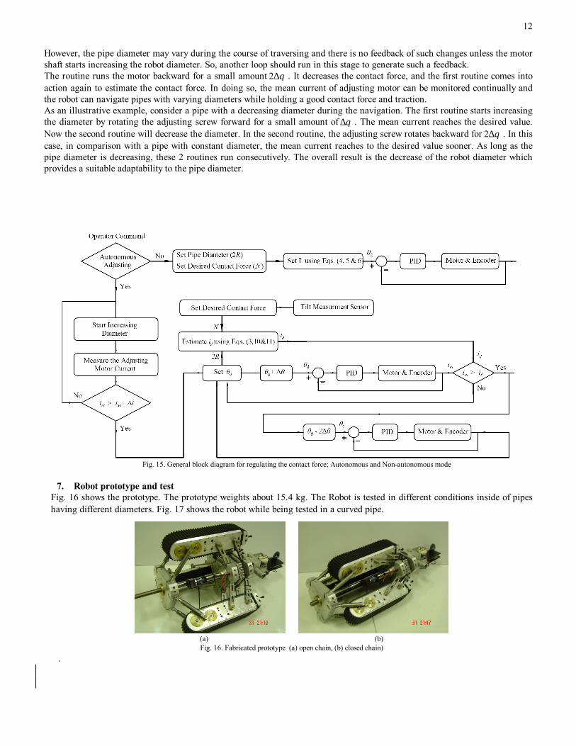
7. Robot prototype and test
Fig. 16 shows the prototype. The prototype weights about 15.4 kg. The Robot is tested in different conditions inside of pipes having different diameters. Fig. 17 shows the robot while being tested in a curved pipe.
(a) (b) Fig. 16. Fabricated prototype (a) open chain, (b) closed chain)
.

13
Fig. 17. Field experiment inside a curved pipe
7.1. Active locomotion and autonomous adjusting To check the algorithm performance introduced in section 6, an experimental setup is provided. In the setup, few rubber obstacles are stuck to the interior surface of a straight pipe. The obstacles are placed circumferentially in 120° apart to decrease the pipe diameter locally. Fig 18 shows a schematic of the setup. In the first stage (point 1), the robot enters the pipe without an obstacle. In the second stage (point 2), the robot passes through a 5 mm obstacle and adapts itself to the new pipe diameter. In the third phase (point 3), the obstacle is passed and the robot reaches to its initial size once again. Finally, in the forth part (point 4), the robot reaches to 10 mm obstacles and decreases its diameter to adapt with this size. Fig 19 and 20 illustrate the result of the autonomous adjusting algorithm while passing the test setup. They show the position of the adjusting motor for Δθ as 100 and 50 degrees respectably.
Fig.18. Schematic of the test bed for autonomous adjusting algorithm
Fig.19. Autonomous adjusting algorithm results while passing over the setup shown in Fig 18 (Δθ=100°)

14
Fig.20. Autonomous adjusting algorithm results while passing over the setup shown in Fig. 18 (Δθ=50°)
The five divisions of the graphs in Fig. 19 and 20 correspond to the passing through parts one to five shown in the figure 18 respectively. In parts 2 and 4, the robot reaches the obstacles and adapts itself to the new pipe diameter. After passing the obstacles, the robot diameter increases again. As can be seen in figure 18, the second obstacle is higher than the first one. This can be seen in Fig. 19 and 20 where the robot size in part 4 is decreased more than part 2. The value of Δθ in the autonomous adjusting algorithm affect the adaptability time as can be seen in Fig. 19 and 20. Increasing the Δθ will decrease the adaptability time. However this (increasing the Δθ) limits the flexibility of the robot because of decreasing the effective length of the springed rear arm. 8. Discussion
While adapting the robot with the pipe size, the power screw expands the robot diameter to push the tracked units against the inner surface of the pipe. The power screw must be actuated until the normal force is reached to a necessary friction between the belt and the pipe wall. It is concluded in section 3 that for a particular normal force on tracks the force in rear arms for a pipe with 250 mm in diameter is greater than 350 mm in diameter. Thus, the critical threshold size is 250 mm in diameter. The force in rear arm causes a deflection in the springs. According to the results shown in Fig, 6 we have about 168 N in the rear arms in ascending a 250 mm diameter pipe. As the springs have the stiffness of 280 Newton per centimeter, thus the deflection of each spring due to 170 N is about 6 mm.
On the other hand, elbow-passing simulation results of section 4.2 shows that the required deflection of the spring is about 8 mm in the worse case. This deflection (8 mm) plus the deflection described in previous paragraph (6 mm) is the maximum required one (14 mm). This maximum deflection should be smaller than the allowable deflection of the springs. The proposed robot has a spring in the rear arm with a maximum deflection of 14 mm. These springs are squared and ground-ends with the outside diameter of 10mm.
When the tracked unit hits an obstacle, the length of the rear arms reduce and the units pass over that obstacle, remaining parallel to the pipe axis because of the parallel-crank mechanism. This can cause some difficulty in ascending and descending vertical pipes. Suppose that the track hits an obstacle while ascending or descending a vertical pipe. The deflection of the rear arm causes the contact between the track and the pipe wall is missed and the contact remains only in the obstacle point. Thus, the contact surface reduces and the needed friction force can not be accommodated. As a result, traversing vertical pipes will encounter with difficulty. Using flexible or movable caring idler ruler solves the problem. Because, the only point that the tracked unit deflect is the obstacle point and the remaining surface of the track stays in contact with the pipe. But the flexibility and movability of the carrying idler ruler have their own complexity which must be studied in future works. It should be noted that the rear spring arms are not only useful in negotiating with obstacles but also help the robot to pass through elbows. However, if the flexible idler roller were only used instead the system would not have enough flexibility in moving through an elbow.
9. conclusion A robot that offers significant improvements, compared with similar ones is proposed. It has wide industrial usage where pipe

15
inspection under various conditions becomes an issue, which includes traversing through vertical pipes, elbows and long horizontal pipelines. Presence of obstacles within the pipelines creates many difficult issue of passing over it. In the proposed mechanism the problem is solved by rear springed arms and increasing the flexibility of the mechanism. The robot is designed to be able to traverse elbowed pipes. This is done with the help of rear springed arms. Thus the rear springed arms are not only useful in negotiating obstacles but also help the robot to pass through moderate elbows. Furthermore, an adjusting power screw is proposed to adapt the robot with the interior pipe diameter. However, the adjusting power screw by contracting tracked units can be useful in passing through an elbow. Moreover, a novel autonomous adjusting algorithm is implemented to assist in better regulation of the contact force without utilizing any force sensor. When the robot moves under autonomous mode, the power screw and related controller provides valuable feature by regulating the contact force between the robot and the pipe wall.
10. acknowledgment This work has been made possible by a grant from IRDO (Industrial Development and Renovation Organization of Iran). The authors would like to thank IRDO for supporting this research. References [1] Kirchner F, Hertzberg J. A Prototype Study of an Autonomous Robot Platform for Sewerage System. Maintenance Autonomous Robots 1997; 4(4):319-331. [2] Kuntze HB, Haffner H. Experiences with the development of a robot for smart multisensoric pipe inspection. Proc. IEEE International Conf. on Robotic and Automation, 1998. p. 1773-8. [3] Roh SG, Choi HR. Differential-drive in-pipe robot for moving inside urban gas pipelines. IEEE Transactions on Robotics 2005; 21(1):1-17. [4] Muramatsu M, Namiki N, Koyama R. Autonomous mobile robot in pipe for piping operations. Proc. IEEE/RSJ International Conf. on Intelligent Robots and Systems 2000. p. 2166-71. [5] Choi HR, Ryew SM. Robotic system with active steering capability for internal inspection of urban gas pipelines. Mechatronics 2002; 16(12):713-36. [6] Zhu Z, Pan Z. Miniature pipe robots. Industrial Robot: An International Journal 2003; 30(6):575–83. [7] Hayashi I, Iwatsuki N, Morikawa K, Ogata M. An in-pipe operation microrobot based on the principle of screw. International Symposium on Micromechatronics and Human Science, 1997. p. 125-9. [8] Horodinca M, Dorftei I, Mignon E, Preumont A. A simple architecture for in-pipe inspection robots. Proc. International Colloquium on Mobile and Autonomous Systems, 2002. p. 61-4. [9] Scholl KU, Kepplin V, Berns K, Dillmann R. Controlling a multi-joint robot for autonomous sewer inspection. Proc. IEEE International Conf. on Robotics and Automation, 2000. vol. 2, p. 1701-6. [10] Wakimoto S, Nakajima J, Takata M. A micro snake-like robot for small pipe inspection. Proc. International Symposium on Micro Mechatronics and Human Science, 2003. p. 303-8. [11] Borenstein J, Granosik G, Hansen M. The OmniTread serpentine robot for industrial inspection and surveillance. International Journal on Industrial Robots, Special Issue on Mobile Robots 2005; 32(2):139-48. [12] Fukuda T, Hosokai H, Uemura M. Rubber gas actuator driven by hydrogen storage alloy for in-pipe inspection mobile robot with flexible structure. Proc. IEEE International Conf. on Robotics and Automation, 1989. p. 1847–52. [13] Aoshima S, Tsujimura T, Yabuta T. A miniature mobile robot using piezo vibration for mobility in a thin tube. Transactions of ASME, Journal of Dynamic Systems, Measurements and Control 1993; 115: 270-8. [14] Anthierens C, Ciftci A, Betemps M. Design of an electro pneumatic micro robot for in-pipe inspection. Proc. IEEE International Symposium on Industrial Electronics, 2, 1999. p. 968-72. [15] Zagler A, Pfeiffer F. ‘‘MORITZ’’ a pipe crawler for tube junctions. Proc. IEEE International Conf. on Robotics and Automation, 2003. p. 2954-60. [16] Neubauer W. A spider-like robot that climbs vertically in ducts or pipes. Proc. IEEE/RSJ International Conference on Intelligent Robots and Systems, 1994. p. 1178-85.
.