Embed Size (px)
Citation preview

IMRT Delivery System QA
Thomas J. LoSasso, Ph.D.Memorial Sloan-Kettering Cancer Center
New York, New York
Introduction . . . . . . . . . . . . . . . . . . . . . . . . . . . . . . . . . . . . . . . . . . . . . . . . . . 561MLC Alignment . . . . . . . . . . . . . . . . . . . . . . . . . . . . . . . . . . . . . . . . . . . . . . 563Leaf Positioning . . . . . . . . . . . . . . . . . . . . . . . . . . . . . . . . . . . . . . . . . . . . . . . 564Light Field Projection . . . . . . . . . . . . . . . . . . . . . . . . . . . . . . . . . . . . . . . . . . . 566Mechanical Measurement Of The Gap (Feeler Gauge) . . . . . . . . . . . . . . . . . 567Film Techniques . . . . . . . . . . . . . . . . . . . . . . . . . . . . . . . . . . . . . . . . . . . . . . . 568Clinically Oriented Test Fields . . . . . . . . . . . . . . . . . . . . . . . . . . . . . . . . . . . . 570Gap Width (DMLC Procedures —Varian Only) . . . . . . . . . . . . . . . . . . . . 572Narrow Sliding Window . . . . . . . . . . . . . . . . . . . . . . . . . . . . . . . . . . . . . . . . . 572DMLC Output Vs. Static Field . . . . . . . . . . . . . . . . . . . . . . . . . . . . . . . . . . . . 573DMLC Output Vs. Gantry And Collimator Angles . . . . . . . . . . . . . . . . . . . . 573DMLC Output, Off-Axis Perpendicular To Leaf Motion . . . . . . . . . . . . . . . 574DMLC Output, Off-Axis Parallel To Leaf Motion . . . . . . . . . . . . . . . . . . . . . 575Beam Characteristics For Small MUs . . . . . . . . . . . . . . . . . . . . . . . . . . . . 576Leaf Motor Issues . . . . . . . . . . . . . . . . . . . . . . . . . . . . . . . . . . . . . . . . . . . . . 577Leaf Speed . . . . . . . . . . . . . . . . . . . . . . . . . . . . . . . . . . . . . . . . . . . . . . . . . . . 577Motor Calibration Failures . . . . . . . . . . . . . . . . . . . . . . . . . . . . . . . . . . . . . . . 578Communication/Timing Errors . . . . . . . . . . . . . . . . . . . . . . . . . . . . . . . . . . 580Log File Analysis (Varian Only) . . . . . . . . . . . . . . . . . . . . . . . . . . . . . . . . . 582Interleaf Transmission . . . . . . . . . . . . . . . . . . . . . . . . . . . . . . . . . . . . . . . . . 584MLC Intercomparison . . . . . . . . . . . . . . . . . . . . . . . . . . . . . . . . . . . . . . . . . 585Auxiliary Systems . . . . . . . . . . . . . . . . . . . . . . . . . . . . . . . . . . . . . . . . . . . . . 587Frequency Of Checks . . . . . . . . . . . . . . . . . . . . . . . . . . . . . . . . . . . . . . . . . . 588Summary . . . . . . . . . . . . . . . . . . . . . . . . . . . . . . . . . . . . . . . . . . . . . . . . . . . . 589References . . . . . . . . . . . . . . . . . . . . . . . . . . . . . . . . . . . . . . . . . . . . . . . . . . . 590
Introduction
Multileaf collimator (MLC) use is increasingly common in radiation therapy clinicsthroughout the world. These devices are well established as a replacement for conven-tional blocks in the majority of treatment sites where static field techniques are usedfor conventional 3-D conformal radiation therapy (3DCRT). At the present time onlya small percentage of MLC-equipped centers are using the MLC for intensity-modu-lated radiation therapy (IMRT), even though the technology has been commerciallyavailable for almost 10 years. The hesitance is in large part due to the complexity ofthe technical aspects of planning and delivery. Before this new technology can besafely implemented, each component of the process must be understood by the users,and a comprehensive quality assurance (QA) program should be in place. A QAprogram will need to address treatment-planning systems, delivery issues involving
561

MLC mechanics, electronics, and software, and patient treatment verification. Onlydelivery issues will be presented here.
In the broad sense, QA for IMRT delivery encompasses acceptance testing,commissioning, routine MLC QA, and patient-specific QA. It begins at the time ofinstallation of new equipment or at the time an existing MLC is upgraded for use withIMRT in order to affirm the capability for accurate IMRT with the specific MLC.Commissioning implies the accurate acquisition of the treatment planning parametersspecific to IMRT, rigorous testing of the dose calculation algorithm under the increaseddemands of intensity modulation, and ancillary techniques such as respiration gatingand the splitting of large fields. Periodic MLC-specific QA checks of the stability ofthe mechanical aspects of the MLC, i.e., leaf positioning, and the dosimetric aspectsof the linac for small numbers of monitor units (MU), i.e., linearity and symmetry,ensure that when the treatment parameters are correctly set, the correct dose is deliv-ered. Verification of the integrity of the treatment plan from the planning through thedelivery stages (patient-specific QA) is the last component. These procedurescomplement each other, and together they ensure accurate dose delivery.
The QA for MLC used in static mode, conventional 3DCRT, is relatively simple.Similar to the procedures required for jaws and blocks, the QA checks involve mechan-ical alignment of the MLC to the accelerator and leaf position reproducibility (Mubata,Childs, and Bidmead 1997; Hounsell and Jordan 1997). The QA procedures specificto the use of IMRT present special issues for dose delivery compared to 3DCRT. Hard-ware and software for MLC are still relatively new to the end users in the clinic, andthe potential for dosimetric errors is still not well understood, while the consequencesof such errors may be clinically significant. Individual treatment centers should expecta learning curve for understanding novel treatment planning and QA issues. The urgeto implement IMRT at individual therapy centers should be tempered while theseissues come into focus and are addressed at each center.
In general, when MLCs are used to perform intensity-modulated treatments, theyrequire more stringent tolerances and, in turn, a more involved QA program. Tests usedfor static QA of the MLC need to be redesigned to achieve the required accuracy. Thisemphasis is justified if one considers that for static treatments these parameters onlydefine the dose near the borders of the field; depending upon the proximity of abut-ting critical tissues, 1 to 2 mm uncertainty of the leaf positions is acceptable. Periodicchecks of the projected leaf positions with graph paper at isocenter are sufficient forthis purpose. However, for IMRT, the leaves modulate the dose delivered throughoutthe target volume; more specifically, the dose delivered with IMRT is sensitive to thewidth of the gap defined by each leaf pair. Then, it is only a matter of assuring thatthe leaves are in the correct position at each moment during treatment. Regardless ofMLC designs, or whether the delivery mode is segmental (SMLC) or dynamic(DMLC), these tests should stress the precise execution of the gap width defined byopposing leaf positions; and for DMLC, the ability of the leaves to maintain their spec-ified leaf speed is also important.
It is necessary to identify sources of leaf positioning error for the specific MLCdesign, and to develop QA tests and frequencies to detect these mechanical problems
562 Thomas J. LoSasso

before dose errors become significant. Analysis of QA data to track the long-term stabil-ity of MLC performance can reveal patterns of MLC failure. These areas then need tobe monitored closely to ensure that the planned dose is delivered accurately and repro-ducibly. Manufacturer’s modifications to MLC hardware and software often followfrom an analysis of the frequency and severity of malfunctions during clinical use.
This chapter will focus on dose delivery related QA procedures applicable toacceptance testing and routine MLC QA specific to IMRT. Some of these methods usestatic fields; they are applicable to all three MLC designs, Siemens, Elekta, and Varian.However, many of the tests rely on dosimetric measurements using the dynamic mode,and so are only applicable to the Varian MLC.
MLC Alignment
As for the movable jaws and conventional metal-alloy blocks, the alignment of theMLC leaves affects the spatial uncertainty between the peripheral extent of the radi-ation beams and the perimeter of the target volume. For IMRT, MLC alignment in thedirection of leaf travel affects the registration of the intensity-modulation (IM) patternsbetween fields altering the composite dose distribution for the plan and also shifts theIM dose distribution for each individual field relative to the patient’s anatomy. In someregions, such as when the spinal cord is to receive a low dose, dose gradients may bevery large within an IMRT field, as much as 10% per millimeter, similar to using ametal conventional block to shield the cord. Fortunately, the effect from one field is,in general, diluted by the dose from the other IM beams; on the other hand, IMRT fieldshave more frequent gradients than conventional fields. Misalignment of the MLC inthe direction perpendicular to leaf motion typically shifts the dose distributions for allthe fields in the same direction with respect to the patient anatomy, comparable to asystematic patient setup error.
Alignment in the direction of leaf motion, including leaf bank skewness and center-line offset can be readjusted via leaf calibration using the alignment of the jaws as aguide. Alignment in the direction perpendicular to leaf motion is fixed at the factory.Even optimal alignment of the MLC does not ensure perfect registration betweenfields. Gantry sag, the displacement of the field in the radial direction, is maximal atgantry angles of 0° and 180°, while gantry roll is maximal at 90° and 270° and shiftsthese fields vertically downward. Similar problems exist for IM fields delivered withfixed compensators.
Misalignment of the MLC relative to the isocenter can be evaluated with thefollowing procedure. A film is irradiated with two complementary leaf patterns, whichnominally suggest a uniform field. For MLC with an interleaf space coincident withthe central axis (Varian and Elekta), the patterns are similar to those illustrated in figure1. For this leaf configuration, the fields match at the central axes. When the center leafoverlies the central axis (Siemens), the match line perpendicular to leaf motion isshifted off the axis by 0.5 cm. Ideally, the image would appear as in figure 2a, a uniformfield with a low-density strip from Top to Bottom, corresponding to tongue-and-groove
IMRT Delivery System QA 563

underdosage. MLC leaves with rounded edges (Varian and Elekta) will yield a high-density strip from Left to Right if their digital readouts are calibrated to the light fieldedge, corresponding to added leakage through the rounded edges of the opposedleaves. If the leaves are calibrated using the radiation field edge, then the high-densityregion will appear relatively uniform. Doubly focussed MLC leaves (Siemens), intheory, should also be uniform from Left to Right. A second image is produced withthe same leaf patterns (center leaf reversed for the Siemens MLC), but with the colli-mator rotated exactly 180° between fields. The density change of the strips in thisimage is proportional to the misalignment of the MLC and can be calibrated with athird image, figure 2b, using the same two fields as for figure 1, but introducing a 1mm shift in each directions, simulating an 0.5 mm misalignment (0.5 mm is a reason-able tolerance limit), in both the radial and transverse directions. These images maybe visually evaluated or scanned. These images may be obtained at other gantry anglesas well.
Figure 1. Complimentary leaf patterns to test the MLC alignment.
Leaf Positioning
For conventional 3DCRT, the accuracy of static field edges, whether defined by theMLC, blocks, or the jaws, only affects the high gradient regions near the borders ofthe target volume or critical structures. In these static treatments, 1 mm errors areusually tolerated. In contrast, the dose delivered with IMRT, whether SMLC or DMLC,can be very sensitive to errors in the calibration of leaf position (Budgell et al. 2000).Therefore, leaf movements must be executed much more precisely.
For DMLC, the impact of leaf calibration is illustrated in figure 3. Dose errors forfixed width gaps moving at constant speed are proportional to gap errors and inverselyproportional to the gap width (ignoring leaf transmission). For example, if the nomi-nal gap width is 2 cm, then a gap error of 1 mm, introduced by one or both leaves ofa pair, will produce a 5% dose error. In clinical DMLC fields, neither the gap width
564 Thomas J. LoSasso

Figure 2. Composite images testing the alignment of the MLC using the leaf patternsfrom figure 1 for a Varian MLC. (a) Uniform field is interrupted by a tongue-and-groove
underdose (vertical band) and leakage between leaf faces (horizontal band) when the leavesare calibrated using a feeler gauge or the light field. If the calibration is to the radiation fieldedge, the dark band should disappear. In either case, symmetry indicates perfect alignment.(b) The asymmetry shown here corresponds to 0.5 mm misalignments both perpendicular
and parallel to leaf motion.
Figure 3. Relationship between dose error and gap error for DMLC fields. For the range ofgap widths typical of DMLC fields, dose errors as a percent of dose delivered are shown as afunction of the gap width error. Gap calibration error of ~0.2 mm translates to dose error of~1% for typical DMLC fields. These numbers apply to SMLC as well, although the gap anddose errors are distributed differently. These curves do not account for transmission throughthe leaves, which will reduce the percent dose errors somewhat. [Reprinted from A Practical
Guide to Intensity-Modulated Radiation Therapy, MSKCC staff. © 2003, with permissionfrom Medical Physics Publishing.]
IMRT Delivery System QA 565
nor the leaf speeds are fixed; nevertheless, the average dose error is inversely propor-tional to the average gap width, for which 1 to 4 cm is typical (LoSasso, Chui, andLing 1998). For SMLC, overlapping or underlapping of abutting field segments leadto hot or cold spots in the abutment regions of approximately 13% mm–1 and 17% mm–1
of the average dose for the abutting segments, for 6 and 18 MV photon beams, respec-tively (Low et al. 2001). SMLC fields, which approach the resolution of DMLC fields,will experience the same average dose error throughout the field, although the errorswill be concentrated in the abutment regions. For both SMLC and DMLC, if averagegap calibration error is less than 0.2 mm, then the average dose error from this sourcein typical fields will be less than 1%.
A leaf calibration error, which shifts both leaves of a pair in the same direction bythe same amount, will not produce a dose error in the usual sense; instead, the dosedistribution for the individual leaf pair will be shifted. Potential problems may becomeapparent when the modulated fields are combined depending upon the magnitude ofthe shift, although such errors will be reduced more or less by the other fields. Thisscenario demonstrates the subtle, but important distinction between leaf position errors,which may be offsetting, and gap width errors. Precision QA test methods should focuson the stability of the gap width, rather than the leaf position, since gap width is a betterindicator of dose delivery, and because it is easier to measure on a periodic scheduleusing mechanical and dosimetric procedures.
Calibration of MLC leaf positions should be performed with methods suggestedby the manufacturer (Boyer et al. 2001). However, the manufacturer’s specificationsfor leaf positioning accuracy, while adequate as a block replacement in static fields,may not be suitable for IMRT applications. Fine calibration and periodic checking ofthe leaf position and gap width calibration should be performed over the clinically usedrange of travel. There are many ways to carry out these checks; a few categorical exam-ples will be described here.
Many of the following tests may be performed at different gantry and collimatorangles to observe the effect of gravity and friction on leaf positioning and speed. It isimportant to establish baseline values for undesirable backlash as all mechanicalsystems have inherent tolerances, which allow their components to move without bind-ing. It is wise for physicists and engineers to acknowledge and understand the effectsthat these tolerances introduce into treatments.
Light Field Projection
Prior to implementation of IMRT, periodic QA procedures for leaf position may haveconsisted of simply checking the field sizes using the field light projections of the leafends onto graph paper at the isocenter, similar to the calibration of the jaws. Unlikethe jaws however, the light field and radiation field may not agree. The rounded leavesof the Varian and Elekta MLC allow significant transmission in the first millimeter;consequently, the radiation field edge defined by the 50% dose is shifted under the leafby a fraction of a millimeter. The correct position of the leaves as measured by the light
566 Thomas J. LoSasso
field will obviously depend upon whether the calibration of the digital readout is basedupon the light field or the radiation field. This procedure is consistent with the solefunction of the MLC for static fields, that is, to shape the field edges. While this testis coarse by IMRT standards, it does provide a quick visual assessment of the MLCto a precision of about 0.5 mm, both on and off the axis and is useful when trou-bleshooting problems and machine down time is critical.
Mechanical Measurement Of The Gap (Feeler Gauge)
Since the delivered dose in IMRT fields is critically dependent upon the gap width, adirect independent measurement of the gap is worthwhile. The absolute calibration ofthe gap width defined by an opposed pair of leaves is obtained by setting a small gap,perhaps 1 mm (at isocenter distance). A feeler gauge having good precision (0.001 in.or 0.025 mm) is then inserted between the ends of opposing pairs of leaves. Forrounded leaves (Varian and Elekta), the gap is measured at the center of the leaf; forfocused leaves (Siemens), the measurement point is at the leaf edge closest to isocen-ter. The gauge should indicate the value of the gap demagnified to the aperture definingpoint at the MLC (e.g., 0.51 mm for a 1 mm gap for the Varian MLC, which is centeredat 51 cm from the source). Each of the pairs of leaves can be measured in the sameway (although by other methods), but observing the projections of the light field orthe radiation field is more practical for determining the relative calibration of theremaining leaf pairs. The exception is the Varian MLC, where the leading edges of theleaves always form a straight line. Then by equalizing the gap between two pairs ofleaves, the banks of leaves will be parallel to each other; the skewness and centerlineoffset can then be adjusted using the light field.
Alternatively, the Millennium™ MLC series features a “Field Alignment Tool”1,which when attached to the head of the machine between the banks of leaves, can beused with the feeler gauge to adjust the skewness and offset of the leaves as well asthe gap. Using the feeler gauge at other gantry and collimator angles will assess theeffects of gravity on the gap. Mechanical backlash due to gravity affects opposingleaves in the same direction and, therefore, the effect of backlash on the gap widthshould be less than its effect on the positions of the corresponding leaves individually.
The above procedure can also be used to verify the gaps at off-axis positions. Onceagain, this is quick to do for a single leaf pair. Narrow gaps at isocenter for the rangeof leaf travel can be defined as individual fields and consecutively set and measuredat the MLC with the feeler gauge. The measured gaps should correspond to the set gapsdemagnified to the MLC (with an additional off-axis correction provided for the VarianMLC from the MLCtable.txt file). Such a series of measurements is shown in figure4 for a Varian Millennium 120 MLC. Upper and lower bounds correspond to the widthsof the gauge, which are slightly larger and smaller than the gap, respectively.
IMRT Delivery System QA 567
1 “MLC User Guide”, (1999). Varian Associates, Inc., Oncology Systems, Palo Alto, CA

Figure 4. Verification of 0.5 mm (at isocenter) gap widths at off-axis positions using a feelergauge. Measurements at the Varian MLC are magnified to the isocenter with an additionalcorrection provided from the MLCtable.txt file. Values are plotted for widths of the gauge
that are slightly larger (upper) and smaller (lower) than the gap.
Film Techniques
Radiographic film is a useful tool for verifying relative leaf position and gap widthaccuracy with the so-called “picket fence.” There are many variations of this technique,but they all provide an assessment of the positioning of each MLC leaf individuallyrelative to the alignment of the other leaves. Some methods irradiate abutting fieldsto generate uniform patterns at the junctions (Boyer et al. 2001; Low et al. 2001).Others irradiate narrow bands at specified intervals (Chui, Spirou, and LoSasso 1996).In either case, the technique is to irradiate a film-loaded cassette or Kodak Ready Packfilm without additional buildup at isocenter using the lowest energy available, proba-bly 6 MV X-rays, to obtain the sharpest image. After a brief series of irradiations usingabutting fields or narrow bands using static, segmented fields or dynamic fields, thefilm can be processed and evaluated. The dose uniformity along the match lines andbands is sensitive to even small deviations of individual leaves. Discontinuities betweenadjacent leaves are easily detected with the naked eye as in figure 5 for a Varian Mark2 MLC, where relative errors, ±0.5 and ±0.2 mm, in leaf positions are intentionallyintroduced for demonstration purposes in the image on the right. The reference imageon the left does not contain errors. Figure 6 shows bands extending to ±14 cm later-ally for a Varian Millennium MLC. An accurate scale can be superimposed upon thefilm image to observe the absolute accuracy of the leaves; a 4 × 4 cm grid is super-imposed on the bands in this image. These films may be obtained at other gantry anglesto observe the variations in leaf positions as when influenced by gravity. Commercialscanning and digital analysis routines2 are available for those who prefer a more objec-tive evaluation.
568 Thomas J. LoSasso
2 Radiological Imaging Technology, Denver, CO.

Figure 5. Film test to determine relative leaf positioning. The film image on the right has leaves intentionally shifted by –0.5 to +0.5 mm to demonstrate the method.
The image on the left does not have errors. [Reprinted from A Practical Guide to Intensity-Modulated Radiation Therapy, MSKCC staff. © 2003, with permission
from Medical Physics Publishing.]
Figure 6. Film test to determine absolute leaf positioning accuracy. The bands extend to ±14 cm laterally for a Varian Millennium™ MLC. An accurate scale can be superimposed
upon the film image to observe the absolute accuracy of the leaves; a 4 × 4 cm grid is superimposed on the bands in this image.
IMRT Delivery System QA 569

Clinically Oriented Test Fields
Identifying the source of a problem is not always straightforward, especially if morethan one component of the IMRT process may be the source of the problem. A prereq-uisite for accurate IMRT treatment is careful and ongoing assessment of the dosedelivery as compared with the dose calculations for standard treatment conditions.However, dose calculations are based upon assumptions and approximations, whichmay not hold under more rigorous conditions.
Hypothetical IMRT test cases and clinical dose distributions selected from actualpatient’s fields for a variety of simple to complex targets can be planned, delivered,and measured to evaluate the overall accuracy of the system (Xing et al. 1999; LoSasso,Chui, and Ling 2001; Van Esch et al. 2002). Verification of these fields using two-dimensional high-resolution techniques, such as film in flat, cylindrical, or cubicphantoms or electronic portal imaging devices (EPIDs), should be appended to aroutine QA program. Methods are described in detail in the chapter Patient-SpecificQA by Xia. Such dose distribution comparisons evaluate the overall performance ofthe MLC at the level of dose and dose variation actually received by the patient, andthey provide a direct link to the treatment planning system dose calculations. Anotheradvantage is that the use of dose distributions overlays and differences are more famil-iar than standard QA data to many physicians, therapists, and physicists alike.Repeated use of the same fields demonstrates the stability of the delivery system overtime. For departments equipped with multiple MLC, they can also be the basis for anIMRT intercomparison of MLC. Discrepancies can be indicative of irregularities inthe delivery system or the dosimetry measurement system, as well as the dose calcu-lation algorithm or the leaf sequencer. Such tests should be performed periodically aswell as for new MLC, new MLC software, and modifications of the treatment plan-ning algorithms.
As is common in most new clinical treatment strategies, IMRT at Memorial Sloan-Kettering Cancer Center (MSKCC) began with a relatively undemanding treatmentsite, the prostate (Ling et al. 1996). Before IMRT treatments began at MSKCC, weacknowledged three specific parameters, which needed to be re-commissioned for theIMRT dose calculations. These were: (1) the MLC transmission (primary plus scat-ter) through the leaves and interleaf spaces; (2) the added transmission through therounded leaf edges; and (3) output factor for small MLC-shaped fields simulated byan analytical source function (LoSasso, Chui, and Ling 1998). These factors haveminor influences for conventional static fields as the average MLC transmission, 1.5%to 2.0%, is less than that for metal alloy blocks, ~3.5%, the round edge only slightlybroadens the penumbra in these cases, and MLC output factor for a tertiary collima-tor can be ignored in most cases. In contrast for IMRT, transmissions through the leavesand the rounded leaf edges contribute 4% and 10%, respectively, to the delivered doseto the target volume in typical IMRT fields, and small variable gaps between leavesproduce local output variations.
570 Thomas J. LoSasso

Concurrently, as IMRT fields increased in size, modulation, and irregularity, peri-odic QA for clinical fields showed increasing discrepancies in certain cases. QA wasgradually intensified to look at different components of the MLC and to try to iden-tify the problem. After some time we concluded that commissioning parametersneeded to be reevaluated. The average value for MLC scatter, based upon prostate andhead and neck field sizes, was included in the MLC transmission that is applied to allfields; however, it is not accurate for larger IMRT fields. We have refined the sourcefunction, to more accurately calculate MLC output for very small gaps. Additionally,we modeled the interleaf spaces giving the planner the option to evaluate tongue-and-groove effects in individual plans.
Clinical dose measurements indicate potential problems in highly modulated andirregularly shaped fields. Recently, a multi-institution comparison of calculated andmeasured clinical dose distributions indicated that the center-specific dose kernelsderived from deconvolution of ion chamber profiles were inadequate (Van Esch et al.2002). One of the more extreme cases at MSKCC, an IMRT lung field, calculated andmeasured in a flat homogeneous phantom, is illustrated in figure 7. The overlay ofcalculations and measurements shows large variations in dose, 15 to 60 cGy withinthe field, with an average dose of about 30 cGy. The dose difference in figure 7a showsthat discrepancies can be 25% of the average dose (15% of the local dose) in suchfields. Most differences are found near the high dose gradients and can be attributedto inaccuracies in the extra-focal source distribution. Calculations comparing thesource distribution used for figure 7 with a new source distribution are shown in figure8. The modification appears to have resolved most of the discrepancy. It should benoted that these discrepancies would be less in the composite dose distribution due tothe smoothing influence of other fields.
Figure 7. Overlay comparison of calculation (solid lines) and film measurement (dottedlines) for a posterior-anterior (PA) lung field used in an IMRT treatment. The intensity-
modulated dose varies from 10 to 60 cGy.
IMRT Delivery System QA 571

Figure 8. Comparison of dose differences (film-calculation) for the field in figure 6 usingthe (a) old source function and the (b) modified source function. The dose differences
between the two calculations are shown in (c).
Gap Width (DMLC Procedures – Varian Only)
Narrow Sliding Window
If dynamic capabilities are supported, as for the Varian MLC, then alternate dosimet-ric methods with much greater precision are available in addition to the static methodsdescribed in the previous section. As these tests are more quantitative, they allow track-ing of long-term stability. Given that the fluence (and consequently the dose measured)through a narrow gap is critically dependent on gap width, inversely, dosimetricmeasurements can be used as a sensitive monitor of gap width (Wang et al. 1996;LoSasso, Chui, and Ling 1998; Arnfield et al. 2000; LoSasso, Chui, and Ling 2001).For example, an output variation of 1%, which is easily measured, corresponds to avariation of ~0.05 mm for a 5.0 mm wide gap (with the round edge transmission notfactored in). Based upon this relationship, we developed a number of dosimetric proce-dures utilizing an ion chamber or diode array.
572 Thomas J. LoSasso

DMLC Output Vs. Static Field
The stability of the gap can be monitored utilizing an ionization chamber and a 5 mmsliding window beam delivery to measure the output. At the time of monthly x-raybeam output calibration, ion chamber readings for the narrow DMLC field are normal-ized to that measured in the static beam calibration field, using the same setupgeometry to avoid uncertainties arising from changes in monitor chamber calibration;temperature and pressure corrections, and precise setup accuracy are also unnecessary.The long-term results, over a 4-year period from 1998–2002, for several treatmentmachines at MSKCC are displayed in figure 9. Here we plot the ratio of the DMLCoutput to static field output versus time. The variation in radiation output during thisperiod is <1% for all three machines, and is less than that corresponding to the 0.2 mmtolerance on gap width (indicated by the vertical arrow marked 0.2 mm). Given the<1% output variation for the gap width of 5 mm used for the reference DMLC field,the variation would be even less (<0.3%) for typical clinical fields with a gap widthof ~2 cm. The dashed lines in figure 9 indicate adjustments to the calibration para-meters, which led to small changes in the DMLC outputs.
Figure 9. DMLC output stability over time. The ratios of the dynamic field to the referencefield are plotted for six Varian MLCs. The 0.2 mm range in gap width corresponds to a 3%change in the ratio. The dashed lines indicate changes to the calibration parameters in theMLCXCAL files. [Reprinted from A Practical Guide to Intensity-Modulated RadiationTherapy, MSKCC staff. © 2003, with permission from Medical Physics Publishing.]
DMLC Output Vs. Gantry And Collimator Angles
Leaf position variations imposed by the effects of gravity at different gantry anglesshould be documented periodically. Changes in leaf position between gantry anglesare indicative of problems with leaf drive assemblies or carriage supports and can leadto significant dose errors. For SMLC these effects can only be observed with film
IMRT Delivery System QA 573
techniques, using the doubly exposed film test described earlier or using the “picketfence” or similar pattern. Variation in fixed gaps at four orthogonal gantry anglesshould be observed. Scanning is advisable as the changes associated with skewnesscannot be quantified visually. When DMLC is available, dosimetry is an option usingion chambers or diode arrays to measure output changes from narrow gaps at differ-ent points along the gap.
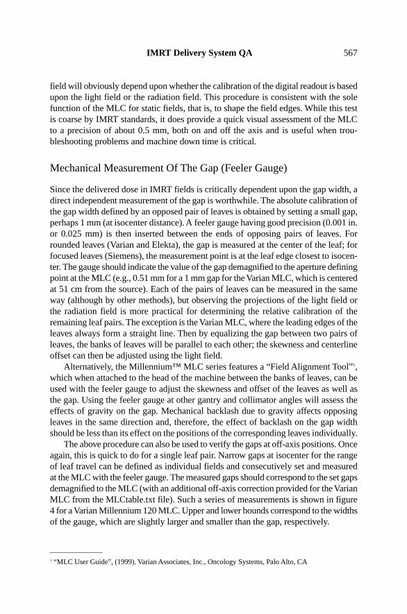
A standard monthly DMLC test for this purpose uses a cylindrical ion chamber(with appropriate buildup cap) at the isocenter; a fixed dose using the 5 mm slidingwindow field described above is delivered, and normalized to the dose from a fixedstatic field, at different gantry and collimator angles. The time trends of dose outputfor six combinations of gantry and collimator angles for four MLC are presented infigure 10. It is apparent that each MLC has a distinctive pattern. The horizontal dashedlines represent the output range that ±0.2 mm gap variation would impose. The verti-cal dashed lines are the adjustments to the calibration as in figure 9. These graphs showthat for any specific set of gantry and collimator angles the clinical output is stable overtime to within about 1%. Furthermore, since daily treatments are generally deliveredwith multiple gantry angles that compensate each other, the deviation due to carriageinstability is usually much less than 1%.
Figure 10. DMLC output stability vs. gantry and collimator angle for four MLCs over time.The DMLC outputs are normalized to the outputs for the static reference field at each angle.
The dashed lines represent ±0.2 mm range in gap width (1% clinical dose variation).
DMLC Output, Off-Axis Perpendicular To Leaf Motion
Off-axis dosimetry measurements indicate the relative skewness at a number of gantryand collimator angles. Data obtained with a linear diode array for a Varian MLC forgantry angles of 90° and 270° are shown in figure 11. The individual diode readings
574 Thomas J. LoSasso

are normalized to the readings with both the gantry and collimator at 0°. The diodessee varying amounts of interleaf leakage. Fitting these data points to straight linesyields the dashed lines for gantry angles of 90° and 270° relative to the 0°-gantry posi-tion. Some backlash is unavoidable in mechanical systems. Fortunately, suchvariations, as observed here at 90° and 270°, tend to compensate each other duringtreatment. Nevertheless, output vs. gantry angle is variable among the MLC, and outputchanges over time may indicate mechanical problems.
Figure 11. DMLC output stability vs. gantry angle measured with a linear diode array.The array is mounted in the blocking tray holder and aligned perpendicular to the direction
of leaf motion. DMLC outputs are first normalized to the static reference field at eachangle and then normalized to the output at 0°. [Reprinted from A Practical Guide
to Intensity-Modulated Radiation Therapy, MSKCC staff. © 2003, with permissionfrom Medical Physics Publishing.]
DMLC Output, Off-Axis Parallel To Leaf Motion
A dynamic slit field can be used to verify the off-axis gap width accuracy dosimetri-cally. The method compares symmetry and flatness of relative dose profiles for an openfield with that for a 1.0 cm wide dynamic field moving at a constant speed (cm/MU).Measurements may be obtained at arbitrary intervals with an ion chamber, a detectorarray, or film. Ideally, the normalized dose profile for the dynamic field should mimicthat for the open static field.
The gap-width accuracy at off-axis positions verified with ionization measure-ments for one MLC is shown as relative dose profiles (i.e., normalized to the dose atthe central axis) in figure 12a and 12b for 6 MV X-rays. Figure 12a shows the staticfield and DMLC field profiles and the ratios of these profiles for each of three fields,centered at the axis and at ±8 cm off-axis at a depth of 10 cm. Near the central axis,the open field and dynamic profiles agree within 0.5%; however, at 10 cm from the
IMRT Delivery System QA 575

axis, the ratio of the profiles decreases by ~2%. This decrease is not due to changesin the gap-width, the measured transmission also decreases with increasing off-axisdistance, to 92% of the central axis transmission at 10 cm off-axis. Figure 12b showsthat the ratios of the profiles for the DMLC fields and the static fields are much flat-ter, once the transmitted component of the dose is removed from the DMLC readings.Thus, the width of the gap for this MLC is relatively constant across the field.
Figure 12. Measured dose profiles for a narrow, 0.5 cm, DMLC field are compared withthose for an open static field. Due to the 15 cm field width limitation, fields are centered atthe central axis and at ±8 cm off axis. (a) Ion chamber measurements at 1 cm intervals are
normalized to the central axis. (b) The ratio of DMLC to open field is flat once the variationin off-axis transmission is measured and corrected for. [Reprinted from A Practical Guideto Intensity-Modulated Radiation Therapy, MSKCC staff. © 2003, with permission from
Medical Physics Publishing.]
Beam Characteristics For Small MUs
The delivery of IMRT using SMLC with Siemens and Elekta requires that the beambe cycled off and on (step and shoot). As the number of segments increases providingmore control points, the monitor units (MUs) per segment will decrease. For complexintensity-modulated patterns with many subfields, large numbers of segments may bedelivering small MU values, less than 2 MU (Ezzell and Chungbin 2001; Xia, Chuang,and Verhey 2002). For example, a 200 cGy prescribed daily fraction delivered with a
576 Thomas J. LoSasso

100 segment plan will average only 2 MU per segment. Since such small MU settingsare outside the range of conventional treatments, the scope of acceptance testing andQA procedures do not normally address this issue.
Testing the accuracy of beam fidelity, i.e., dose output, symmetry, and flatness, forsmall MU can be done with an ion chamber positioned sequentially at the central axisand at four orthogonal off-axis points in a static field. At each point the dose for a fixednumber of MU, X MU, is measured. At each point for X-1 MU segments the dose isalso measured and then summed for comparison. Measurements may also be madewith 2-D detector arrays or film. A summary of the experiences of small numbers ofmonitor units for several different machines concluded that individual centers need tomake such measurements on their particular accelerator approximately monthly toensure reliability (Webb 2001).
Leaf Motor Issues
Leaf Speed
Leaves have a maximum speed that is specified by the manufacturer. On occasion,leaf motors will not be able to maintain this speed during normal operation. Slowingis a symptom of excessive wear of the motor or other leaf assembly components. Abuildup of dirt and grease migrating between the flat leaf surfaces from componentsof the drive mechanism may also tend to bind adjacent leaves; this possibility shouldbe eliminated first. Variation in the maximum available leaf speed of individual leaveswill influence treatment times since segments within an SMLC field will requirelonger leaf setup times.
For DMLC, which is only currently available with the Varian MLC, the reductionof the maximum leaf speed will have two possible effects. If a leaf is unable to main-tain its programmed speed while the beam is on, then the MLC software will modulatethe dose rate by increasing the number and duration of beam holdoffs during deliv-ery, and thereby increase treatment times. More importantly, the delivered intensityprofile may also differ from the prescribed profile if a leaf is lagging behind due toleaf speed issues, with or without beam holdoff indication. Thus, leaf speed is consid-ered a more important QA issue for DMLC than for SMLC delivery, where the doseis unaffected. Detection of reduced leaf speed for an individual motor should be partof a QA program, so that the problem may be rectified by a service engineer.
The stability of leaf speed and the effects of leaf acceleration and deceleration onthe delivered intensity profiles for DMLC have been recognized for several years(Chui, Spirou, and LoSasso 1996). To test the stability of leaf speed, speciallydesigned leaf sequence files move pairs of leaves at constant speeds ranging from lowto maximum speed. If the leaf speeds are constant across the field, then the measureddose profiles should be uniform. If leaf speeds are unstable, fluctuations would appearin the delivered profiles. Since leaf speeds are varied between programmed DMLCsegments, the significance of acceleration and deceleration was also tested by inten-
IMRT Delivery System QA 577

tionally interrupting the beam and then resuming the irradiation, which was judgednot to be a concern.
Sub-par leaf speed can often be visually detected relative to other leaves when theleaves are moved at their maximum velocity during field setup or leaf retraction or byusing a leaf exercise pattern designed for this purpose, which moves leaves in and outof the field. If the problem is subtle, it may only be noticeable during leaf movementsat certain gantry angles when gravity is a compounding factor.
During a DMLC treatment with the Varian MLC, excessive beam hold-offs for oneor more fields are an indication of such a problem. The therapists performing the treat-ments should have an ear open for these telltale signs and report them for servicing. Amore objective approach is to evaluate DMLC leaf positions recorded by the VarianMLC controller in log files during delivery. The Dynalog File Viewer3, a software toolfor evaluating leaf positioning during IMRT delivery, tabulates leaf position errors [rootmean square (rms) deviation of monitored and actual leaf positions for individual leaves]based upon their magnitude and frequency of occurrence during treatment. A test filewhich moves all the leaves in and out of the field in an alternating pattern at a speedclose to the maximum can then be evaluated with the Dynalog File Viewer to identifyerrant leaf behavior. Individual leaves are suspect if their deviations appear significantlylarger than the average for all the leaves. Performing such a leaf speed test at gantryangles of 90° and 270° may be best to incorporate the gravity factor as well.
Motor Calibration Failures
Electromechanical components of the MLC may fail at any time. This may take theform of an abrupt failure, requiring immediate replacement of the part before treat-ment can resume, or, perhaps more troubling, it may be a gradual deterioration,requiring careful monitoring. Deterioration of motor speed has been described earlier.Another concern has to do with the long-term reliability of the primary encodersaffixed to the Varian leaf motors; it is apparently related to the amount of usage of indi-vidual leaf motors. Chronic drift of the calibration of the leaf position encoder has beenthe principal symptoms of leaf motor failures for this MLC design until recently.
The data in figures 13 and 14 summarize the history of MLC leaf motor failureson three Varian MLC machines used primarily for DMLC treatments since 1996 atMSKCC. Approximately 80% of patients—~30 patients/day, 5 fields/patient—on twomachines, 245 and 445, have been IMRT prostate patients (prior to this time,1992–1995, these MLC have been used primarily for static MLC treatments). In figure13, the increased frequency of motor failure near the central axis, indicated by color,and multiple failure, indicated by numbers, is consistent with those leaves used forprostate fields. The solid lines in figure 14 graph the chronology of motor replace-ments. For each MLC, leaf motor failures became more frequent after the initiationof DMLC treatment. Leaf position errors, caused by calibration drift, were increas-
578 Thomas J. LoSasso
3 “Dynalog File Viewer, Reference Guide,” (2001) Varian Associates, Inc., Oncology Systems, Palo Alto, CA.

ingly detected during QA procedures and patient treatments. The frequency of MLCreinitialization was gradually increased during the treatment day. Eventually, begin-ning in 1998 the replacement of marginally performing motors became part of the QAprogram. With DMLC QA specifically targeting this problem, leaf drive motors werereplaced at a steady rate between 1998 and 2001. Based on our QA records we haveestimated what the MLC motor replacement rate would have been had we initiated thisprophylactic motor replacement policy in 1995. These are shown as dashed lines infigure 13. It is postulated that the repeated abutment of opposing leaves especiallyduring IMRT delivery caused many of these leaf motors to fail prematurely. New soft-ware developed by the manufacturer, with a 0.5 mm minimum gap criterion, wasinstalled in June 2001, indicated by the vertical dashed line in figure 13. While it istoo early to be definitive, the rate of motor replacement appears to have decreased atabout the same time. Furthermore, the primary cause of leaf motor failure is no longercalibration drift.
Figure 13. Leaf positions where motors have been replaced are shown in color for threeMLC. Numbers indicate multiple motor replacements. The pattern of replacing centrally
located motors for the MLCs in rooms 445 (left) and 245 (center) is consistent with the useof these MLCs almost exclusively for prostate treatments. [Reprinted from A Practical
Guide to Intensity-Modulated Radiation Therapy, MSKCC staff. © 2003, with permissionfrom Medical Physics Publishing.]
IMRT Delivery System QA 579

Figure 14. Cumulative motor replacements vs. time for three MLCs. The solid curves arethe actual replacements. The dashed curves indicate that some motors would have been
replaced earlier based upon the replacement criteria adopted in 1998. The vertical dottedline indicates the introduction of the 0.5 mm minimum gap criterion for moving leaves.
[Reprinted from A Practical Guide to Intensity-Modulated Radiation Therapy,MSKCC staff. © 2003, with permission from Medical Physics Publishing.]
The problem just described for the Varian MLC stems from the count losses bythe primary encoder, an integral part of the motor assembly. It becomes more severeduring the course of the treatment day, assuming the MLC is initialized (self-cali-brated) in the morning using its internal optical calibration system. On occasion thatthe count losses of a primary encoder become excessive, leaf position errors couldexceed 0.5 mm at isocenter. Reinitializing the MLC will temporarily alleviate the prob-lem, but position errors may go unnoticed since the secondary position interlock istriggered only when the discrepancy between the primary and secondary readoutsreaches ~2 mm at isocenter. To safeguard against such errors, potential encoder prob-lems are identified using the picket fence film test described earlier on a semi-weeklyschedule. The film test is performed by a therapist, evaluated by a physicist, and ques-tionable motors are then replaced at the earliest convenience. This condition may existintermittently for several days before detection.
Communication/Timing Errors
A number of studies have recently addressed the subject of communication delays, alsoreferred to as timing errors, overshoot phenomenon, and latency issues, and the subse-quent leaf position errors for the Varian MLC in dynamic mode. The concern arisesdue to the 55+ msec delay before the MLC control system can acknowledge andrespond to the instruction for the next MU segment. In effect, the leaf lags behind itsprescribed position, defined by the index, or fractional MU, in the leaf sequence file,
580 Thomas J. LoSasso

at each moment of the delivery. It may appear as though the leaf speed is the issue,but rather the deviation in leaf position is caused by the communication delay.
For the SMLC mode, these errors mainly affect the delivered dose in the first andthe last segment, which deliver slightly greater and less dose than planned, respectively.Intermediate segments also experience these delays; however, approximately the same“overshoot,” i.e., the ∆MU which is added to the end of each segment, is missing fromthe beginning of each segment. In this case two wrongs make it right; the intermedi-ate segments generally receive the correct MU (Ezzell and Chungbin 2001; Xia,Chuang and Verhey 2002). This is demonstrated in figure 15, where the total MU persegment is varied from 0.25 to 25 at a delivery rate of 400 MU/min. For the smallestMU per segment such that the “overshoot” exceeds the planned MU for the segment,one or more of these intermediate segments may actually be skipped. The graphics infigure 16 illustrates this very clearly. In the upper diagram the planned segments areequal in MU per segment; the first segment delivers more dose and the last segmentless than planned, while intermediate segments receive the correct dose. In the centerdiagram, a small intermediate segment, 3, is bypassed as a result of the overshoot. Thelower diagram indicates the variable nature of the overshoot and the correspondinguncertainty this introduces to all delivered segments.
Figure 15. The relative dose variations among four segments as a function of MU per segment. The dose rate is 400 MU/min on a Varian 2300CD at 6 MV.
[Courtesy of Ping Xia, UCSF.]
IMRT Delivery System QA 581

Figure 16. Schematic showing the effect of an overshoot in the MU delivery. (a) Overshootis constant. Segment 1 is long, 5 is short, 2–4 are unaffected. (b) Overshoot exceeds theplanned MU for segment 3, so it is skipped. (c) Overshoot is variable, so segment 3 is
shorter than planned and segment 4 is longer. (Reprinted from Journal of Applied ClinicalMedical Physics, vol. 2, issue 3, G. A. Ezzell, and S. Chungpin, “The Overshoot
Phenomenon in Step-and-Shoot IMRT Delivery,” pp. 138–128. © 2001, with permissionfrom G. Ezzell and the Journal of Applied Clinical Medical Physics.]
In the DMLC mode, if leaf speeds are allowed to exceed their maximum values,dose rate modulation will result (Low et al. 2001). In this situation the dose is deliv-ered in pulses as the beam holdoff is repeatedly invoked and the leaf deviation varieswithin each pulse; a rippled dose distribution results even though the intended leafsequence is smooth. Another study offers a detailed description of the limitations ofthe delivery control system and proposes sequencing solutions to overcome these limi-tations (Litzenberg, Moran, and Fraass 2002b). However, the fluence modulationintroduced by communication delays into DMLC delivery should also cancel for lead-ing and trailing leaves.
Thus, it may be concluded that for typical clinical situations, i.e., when very smallMU per field and MU per segment are avoided for SMLC and when appropriate leafsequencing parameters (dose rate, leaf tolerance, and maximum leaf speed) are chosenfor DMLC, timing errors will not lead to significant dose errors. There is some concernif these leaf sequences are used for QA purposes, where film and EPID may requireshorter MU; the dose rate should be reduced in this case such that the maximum leafspeed is not exceeded.
Log File Analysis (Varian Only)
Log files are generated by the Varian MLC control software after each IMRT field isdelivered. These files contain the leaf positions as indicated by the primary leaf position
582 Thomas J. LoSasso

encoder attached to each leaf motor. These monitored leaf positions and the prescribedleaf positions are recorded every 55 msec for each leaf. Analysis of these data can bea very useful QA tool, provided the information is properly interpreted. In this regard,it is important that the user understand that these are “monitored” leaf positions do notrepresent the “actual” positions of the leaves. They are the positions of the leaves fromthe perspective of the primary leaf position encoder attached to the leaf motor. Log filesdo not consider errors in the absolute leaf calibration, drift in the leaf calibration overtime, or backlash in the leaf drive mechanism. Nevertheless, analysis of this data canprovide information on the performance of MLC leaves individually.
Several applications of these log files have already been developed. During DMLCacceptance testing, log files were analyzed to study the impact of gantry and collimatorrotations on leaf positioning (MSKCC 2003). The DMLC log files may also beconverted to leaf sequence files which, with the prescribed MU and field size, permitthe calculation of the “delivered” dose distributions (within the uncertainty due to leafcalibration and mechanical backlash) by the treatment planning system. The compar-ison of the delivered dose distributions with the planned dose distributions are usefulto verify normal beam delivery and to study the effects of repeated beam holdoffs,invoked by gating signals, on IMRT dose delivery has been reported (LoSasso et al.2001; Yorke et al. 2000). An example of such a comparison is shown as the dose over-lay and difference in figure 17 for the posterior field of a 5-field DMLC prostatetreatment. The dose difference distribution indicates discrepancies between the plannedand delivered dose distributions of less than 1%.
Figure 17. Comparison of a “delivered” dose distribution derived from a Dynalog file with the planned dose distribution. [Reprinted from A Practical Guide to Intensity-
Modulated Radiation Therapy, MSKCC staff. © 2003, with permission from Medical Physics Publishing.]
Varian has provided a software package, the Dynalog File Viewer, to summarizethe deviations of the leaves from their prescribed positions for leaves that were movingduring the DMLC treatment. These treatment summaries currently only provide numer-ical scores, rms leaf position deviations, which are not directly correlated to dose
IMRT Delivery System QA 583

delivery errors. However, they can be used to evaluate MLC in conjunction with appro-priate test files to identify leaf motors that are not able to maintain their maximum speed.
A very detailed analysis of the Varian Dynalog files has been made to assessroutine QA. (Litzenberg, Moran, and Fraass 2002a). In this study the authors derive,tabulate, and graphically display such quantities as leaf position and velocity devia-tions, gap deviations, and dose discrepancy profiles. They suggest that a routine ofQA sequences be tested and analyzed daily to evaluate MLC performance. Althoughmany of these features would overwhelm the average IMRT user, no doubt a modi-fied version of this software, selecting specific parameters, targeting known problemswould be a valuable QA and troubleshooting tool for the manufacturer to provide witheach IMRT installation.
Interleaf Transmission
All MLC are focused in the direction perpendicular to leaf motion. This requires thatthe leaves are divergent and that the sides of the leaves have an overlapping compo-nent, tongues and grooves or just a single step midway, to reduce the interleaftransmission through the narrow air spaces between the leaves. Variation in transmis-sion for a specific MLC in the direction perpendicular to leaf motion is caused bydifferences between the midleaf thickness and the combined thickness of tongues andgrooves, plus the transmission through the narrow air spaces, which is not completelyblocked by the tongues and grooves. The overlap, which also adds stability, can takea number of shapes, but generally keeps the measured interleaf transmission to lessthan 3%, which is lower than for metal alloy blocks (Boyer et al. 2001).
Another by-product of the overlapping portions of the leaves is the so-called“tongue-and-groove” effect, which can produce an underdose in the interleaf space(van Santvoort and Heijmen 1996; Webb et al. 1997). Interleaf transmissions andtongue-and-groove effects fluctuate between adjacent leaf pairs. They have a morepronounced effect in IMRT than in 3DCRT because the MU are greater for IMRT andbecause the leaves shield the target for a significant portion of the IMRT treatment.For this reason, the range of interleaf transmission should be determined for all theleaves at acceptance testing; variations may also be observed at different gantry andcollimator angles. Later, these findings may explain discrepancies between measuredand calculated doses for individual fields. Fortunately, the magnitude of interleaf trans-mission and tongue-and-groove effects tend to negate each other as fields are combinedin the composite plan.
Interleaf transmission is most easily quantified with film dosimetry using a tissueequivalent phantom and a high-resolution scanner. In general, the interleaf transmis-sion exceeds the midleaf transmission for MLC as shown in figure 18 for Varian Mark2 and Millennium MLC, where the transmission profiles for the blocked fields arenormalized to that for the open field. As measured in phantom, the maximum inter-leaf transmission should not be more than twice the midleaf value. Thefull-width-half-maximum (FWHM) values are ~ 2.5 mm measured in phantom for 6and 15 MV X-ray beams (LoSasso, Chui, and Ling 1998).
584 Thomas J. LoSasso

Figure 18. Interleaf and midleaf transmission profiles (A-side, B-side, and average) for the (a) Mark 2 and (b) Millennium™ 120 MLC. [Reprinted from A Practical Guide
to Intensity-Modulated Radiation Therapy, MSKCC staff. © 2003, with permissionfrom Medical Physics Publishing.]
MLC Intercomparison
For centers with multiple MLC-equipped linacs, a diligent QA program will compareMLC parameters that affect the dose delivered. Values of parameters, such as midleafand interleaf transmissions, variations in leaf position calibration, and output factorsfor small fields, are usually measured with static fields when commissioning the MLC;their comparison is straightforward.
A major concern for IMRT is the fluence through the leaf face. Each MLC designcan be classified as either single- or double-focused. In the double-focused configu-ration (Siemens), the leaves move in an arc; the leaf face and the leaf sides nominallymatch the beam divergence. Single-focused leaves (Elekta and Varian) only have sidesthat are divergent. Since they move in a plane, they have rounded faces, allowing theleaves to maintain a constant penumbra width as the non-focused leaves move awayfrom the central axis in a simple rectilinear motion. This is a complicating factor fordose calculation as the round leaf end transmits more of the primary beam than a flatleaf end, and the transmission is varying with distance from the edge. For the Varianand Elekta MLC, this added fluence will contribute a significant amount of the deliv-ered dose within typical IMRT fields, perhaps 10% or more depending upon thedegree of modulation in the plan. This transmission may vary somewhat with energy,MLC model, and distance from the central axis due to oblique path length throughthe leaf face and off-axis spectral changes. For the Siemens MLC, although the leaffaces are flat and focused to the source, even slight misalignment may introduce addi-tional fluence.
Transmission through the leaf ends can be quantified with measurements of theeffective gap offset (LoSasso, Chui, and Ling 1998; Arnfield et al. 2000; LoSasso,
IMRT Delivery System QA 585

Chui, and Ling 2001). An effective offset for a leaf can be thought of as the amountthat a leaf would need to be retracted to add the same fluence as is transmitted throughthe leaf end. In one method film is used to measure integral dose in phantom for a setof nominal static gap widths including the smallest gap setting allowed with the leavesnot touching. Leaf sequence files have been created for moving gaps with differentfixed widths and constant leaf speed centered at 0, 5, and 10 cm from the central axis.An integrating ion chamber, either in a phantom or in air, serves the same purpose asfilm in the previous method. For each field, static or dynamic, the integrated readingis the sum of the fluence through the gap, the leaf end transmission, and the full leaftransmission. Full leaf transmission is measured using the same jaw setting and detec-tor setup (note: measured transmission is dependent upon irradiation and geometry dueto scatter and interleaf transmission), but with the leaves of the MLC blocking the fieldcompletely. The full leaf transmission varies for each gap field and must be subtractedfrom the measurement. This is derived from the average of the measured transmissionfor the two leaf banks with an adjustment for the spatial (film) or temporal (ion cham-ber) fraction that the detector is shielded by the leaves. The net ion chamber outputs,normalized to a static 10 × 10 cm2 static field at the central axis and a depth of 10 cmfor 6 MV and 15 MV beams, are displayed in figure 19. They are plotted against thenominal gap width and fit with straight lines. The intercept at zero dose yields the effec-tive gap offset. Note that this measurement includes the effect from the uncertainty ofthe leaf gap calibration, the variations in attenuation due to energy and leaf design, andthe limitations of the mechanical components of the MLC system.
Figure 19. Output vs. DMLC gap width. The x-intercept is the effective gap offset due tothe round leaf ends. [Reprinted from A Practical Guide to Intensity-Modulated Radiation
Therapy, MSKCC staff. © 2003, with permission from Medical Physics Publishing.]
586 Thomas J. LoSasso

Effective gap offsets can then be compared for various rooms, MLC models, ener-gies, and off-axis positions. Figure 20 summarizes measured offset values at the centralaxis, 5 cm, and 10 cm off-axis, parallel to leaf motion, for five Varian MLCs with threedifferent leaf designs. For the same nominal energies, variation in the offset value waswithin ±0.15 mm at all positions. Except for the MLC in room 442, the variation in theoffset value at the central axis is within ±0.05 mm. The lower offset for the MLC inroom 442, in part, is due to the slightly lower beam energy observed for this 6 MV beam.
Figure 20. Comparison of measured effective offsets for five MLCs at the central axisand at 5 and 10 cm off-axis for 6 and 15 MV X-rays. [Reprinted from A Practical Guide
to Intensity-Modulated Radiation Therapy, MSKCC staff. © 2003, with permissionfrom Medical Physics Publishing.]
Auxiliary Systems
Where the tumor and/or critical organs are potentially affected by respiratory motion,respiratory gating may be applied during simulation, scanning, and treatment to mini-mize movement. Gating during tumor localization will affect the apparent tumor sizeand location (Nehmeh et al. 2002). Gating during IMRT delivery has an added bene-fit, as intrafraction organ motion can distort the temporal and spatial dependent dosedelivery. Figure 21 illustrates the cyclical motion of a point in the field, perpendicu-lar and parallel to the leaf motion, caused by respiration. The impact on dose deliveryof gating the accelerator beam with a respiratory monitoring system should be tested.This can be performed with film dosimetry techniques or by analyzing log files.
For large target volumes it is sometimes necessary to split fields into twosubfields (figure 22) due to limitations in the field width used for IMRT. Dose distri-bution accuracy in the overlap region of split fields should be tested for clinical cases(Wu et al. 2000).
IMRT Delivery System QA 587

Figure 21. Diagram illustrating the motion of a point in the tumor due to respiratory motionrelative to leaf motion for the sliding window type of treatment. Note: Step-and-shoot
delivery is sensitive to respiratory motion as well.
Figure 22. Diagram illustrating the splitting of large intensity pattern into two subfields.
Frequency Of Checks
It is difficult to set a standard for frequency of performing QA. The frequency will varywith a number of factors including the type of delivery, i.e., SMLC or DMLC, the MLCdesign, the variety of tests used, the length and breadth of experiences of the individ-ual institution, and the feedback of the composite experiences of all institutions withthe MLC hardware and software. Ergonomic issues include the speed and simplicityof the tests, the stability of the parameters being tested for the individual MLC, andthe significance of deviations on the delivered dose to the target and normal tissues.
588 Thomas J. LoSasso

Initially, the type and frequency of tests are performed on a schedule which reflectsunfamiliarity with both the delivery problems and the clinical significance of appar-ent irregularities. Verification of all clinical fields for patient’s plans, though laborintensive, is invaluable in the early stages of IMRT to evaluate the entire planning anddelivery process. Gradually this heightened guard can be relaxed as understanding andconfidence builds in the inherent safety features and a more efficient QA process.
Using MSKCC as an example, where thousands of patients have been treated withIMRT since 1995 and where the current rate is about 200 treatments per day on 14MLC-equipped machines at the center and satellite facilities, routine QA requires lessthan 2 hours per month per MLC or about one-fifth of the daily and monthly QA forthe linac. It is relatively rare that we verify clinical dose distributions for IMRT patients,currently less than 5% of patients have dose verification. Dosimetric evaluation of theentire field of each IM beam for each patient, using standard verification tools, wouldhave overtaxed our medical physics resources and was judged not to be necessary. Indi-vidual patient dosimetry is currently relegated to new treatment sites, new MLC, ornew software. Our current approach integrates existing methods, combining periodicQA and computer verification, to provide the necessary quality assurance in a safe andefficient manner (LoSasso, Chui, and Ling 2001). However, in the years surroundingthe initiation of IMRT, QA with ion chamber and/or film dosimetry was performedfor each field for hundreds of patients. This QA process has obviously evolved withtime; it is likely that this program will be further refined in the future.
This startup intensity should be unnecessary considering the composite experi-ences of such institutions with these devices. Nevertheless, individual treatment centersshould expect a learning curve for understanding novel treatment planning and QAissues. The urge to implement IMRT at individual therapy centers should betempered while these issues come into focus and are addressed at each center.
Summary
This chapter has addressed the quality assurance issues specific to IMRT delivery withan MLC, both for the SMLC and the DMLC modes. It does not address acquisitionof commissioning parameters for the treatment planning system or the routine verifi-cation of treatments, which are discussed in other chapters.
One of the principal concerns for IMRT relative to conventional 3DCRT is themechanical accuracy of the MLC. Leaf positioning and gap width are critical to theaccuracy of the delivered dose in IMRT. Alignment of the MLC to the accelerator,direct and indirect measurements of leaf positions and gap widths, verification of refer-ence static and dynamic fields, and analysis of feedback information provided by theMLC software are discussed. Procedures and results for a variety of mechanical, lightfield, and radiation field measurements using a feeler gauge, graph paper, film, anddosimeters have been presented.
IMRT Delivery System QA 589
References
Arnfield, M. R., J. V. Siebers, J. O. Kim, Q. Wu, P. J. Keall, and R. Mohan. (2000). “A methodfor determining multileaf collimator transmission and scatter for dynamic intensity modu-lated radiotherapy.” Med. Phys. 27: 2231–2241.
Boyer, A., P. Biggs, J. Galvin, E. Klein, T. LoSasso, D. Low, K. Mah, and C. Yu. Basic Appli-cations of Multileaf Collimators: Report of the AAPM Radiation Therapy Committee TaskGroup No. 50. AAPM Report No. 72. Madison, WI: Medical Physics Publishing, 2001.
Budgell, G. J., J. H. L. Mott, P. C. Williams, and K. J. Brown. (2000). “Requirements for leafposition accuracy for dynamic multileaf collimation.” Phys. Med. Biol. 45:1211–1227.
Chui, C. S., S. Spirou, and T. LoSasso. (1996). “Testing of dynamic multileaf collimation.” Med.Phys. 23:635–641.
Ezzell, G. A., and S. Chungbin. (2001). “The overshoot phenomenon in step-and-shoot IMRTdelivery.” J. Appl. Clin. Med. Phys. 2:138–148.
Hounsell, A. R., and T. J. Jordan. (1997). “Quality control aspects of the Philips multileaf colli-mator.” Radiother. Oncol. 45:225–233.
Ling, C. C., C. Burman, C. S. Chui, G. J. Kutcher, S. A. Leibel, T. LoSasso, R. M. Mohan, T.Bortfeld, L. Reinstein, S. Spirou, X. H. Wang, Q. Wu, M. Zelefsky, and Z. Fuks. (1996).“Conformal radiation treatment of prostate cancer using inversely planned intensity-modu-lated photon beams produced with dynamic multileaf collimation.” Int. J. Radiat. Oncol.Biol. Phys. 35:721–730.
Litzenberg, D. W., J. M. Moran, and B. A. Fraass. (2002a). “Verification of dynamic and segmen-tal IMRT delivery by dynamic log file analysis.” J. Appl. Clin. Med. Phys. 3:63–72.
Litzenberg, D. W., J. M. Moran, and B. A. Fraass. (2002b). “Incorporation of realistic deliverylimitations into dynamic MLC treatment delivery.” Med. Phys. 29:810–820.
LoSasso, T., C. S. Chui, and C. C. Ling. (1998). “Physical and dosimetric aspects of a multi-leaf collimation system used in the dynamic mode for implementing intensity modulatedradiotherapy.” Med. Phys. 25:1919–1927.
LoSasso, T., C.-S. Chui, and C. C. Ling. (2001). “Comprehensive quality assurance for the deliv-ery of intensity modulated radiotherapy with a multileaf collimator used in the dynamicmode.” Med. Phys. 28: 2209–2219.
Low, D. A., J. W. Son, E. E. Klein, J. Markman, S. Mutic, and J. F. Dempsey. (2001). “Char-acterization of a commercial multileaf collimator used for intensity modulated radiationtherapy.” Med. Phys. 28:752–756.
MSKCC (Memorial Sloan-Kettering Cancer Center). A Practical Guide to Intensity-ModulatedRadiation Therapy. Madison, WI: Medical Physics Publishing, 2003.
Mubata, C. D., P. Childs, and A. M. Bidmead. (1997). “A quality assurance procedure for theVarian multi-leaf collimator.” Phys. Med. Biol. 42:423–431.
Nehmeh, S. A., Y. E. Erdi, C. C. Ling, K. E. Rosenzweig, E. D. Yorke, O. D. Squire, E. Ford,K. Sidhu, G. Mageras, L. E. Braban, S. M. Larson, J. L. Humm. (2002). “Effect of respi-ratory gating on reducing lung motion artifacts in PET imaging of lung cancer.” Med. Phys.29:366–371.
Van Esch, A., J. Bohsung, P. Sorvari, M. Tenhunen, M Paiusco, M. Iori, P. Engstrom, H.Nystrom, D. P. Huyskeens. (2002). “Acceptance tests and quality control (QC) proceduresfor the clinical implementation of intensity modulated radiotherapy (IMRT) using inverseplanning and the sliding window technique: Experience from five radiotherapy depart-ments.” Radiother. Oncol. 65:53–70.
590 Thomas J. LoSasso

van Santvoort, J. P. C., and B. J. M. Heijmen. (1996). “Dynamic multileaf collimation without‘tongue and groove’ underdosage effects.” Phys. Med. Biol. 41:2091–2105.
Xia, P., C. F. Chuang, and L. J. Verhey. (2002). “Communication and sampling rate limitationsin IMRT delivery with a dynamic multileaf collimator system.” Med. Phys. 29:412–423.
Xing, L., B. Curran, R. Hill, T. Holmes, L. Ma, K. M. Forster, and A. L. Boyer. (1999). “Dosi-metric verification of a commercial inverse treatment planning system.” Phys. Med. Biol.44:463–478.
Wang, X., S. Spirou, T. LoSasso, J. Stein, C.-S. Chui, and R. Mohan. (1996). “Dosimetric vari-ation of intensity-modulated fields.” Med. Phys. 23:317–327.
Webb, S. Intensity-Modulated Radiation Therapy. Bristol, UK: Institute of Physics Publishing,p. 180, 2001.
Webb, S., T. Bortfeld, J. Stein, and D. Convery. (1997). “The effect of stair-step leaf transmis-sion on the ‘tongue and groove problem in radiotherapy with a multileaf collimator.” Phys.Med. Biol. 42:595–602.
Wu, Q., M. Arnfield, S. Tong,Y. Wu, and R. Mohan. (2000). “Dynamic splitting of large inten-sity-modulated fields.” Phys. Med. Biol. 45:1731–1740.
Yorke, E., G. Mageras, T. LoSasso, H. Mostafavi, and C. Ling. (2000). “Respiratory Gating ofSliding Window IMRT.” CD-ROM Proceedings of the World Congress on Medical Physicsand Biomedical Engineering, July 23–28, 2000, Chicago, IL.
IMRT Delivery System QA 591