Embed Size (px)
Citation preview
http://wjst.wu.ac.th Engineering and Physical Sciences
Walailak J Sci & Tech 2015; 12(4): 343-360.
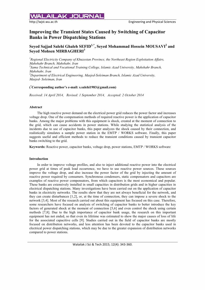
Improving the Transient States Caused by Switching of Capacitor Banks in Power Dispatching Stations Seyed Sajjad Salehi Ghaleh SEFID1,*, Seyed Mohammad Hossein MOUSAVI2 and Seyed Mohsen MIRBAGHERI3 1Regional Electricity Company of Khuzestan Province, the Northeast Region Exploitation Affairs, Mahshahr Branch, Mahshahr, Iran 2Sama Technical and Vocational Training College, Islamic Azad University, Mahshahr Branch, Mahshahr, Iran 3Department of Electrical Engineering, Masjed-Soleiman Branch, Islamic Azad University, Masjed- Soleiman, Iran (*Corresponding author’s e-mail: [email protected]) Received: 14 April 2014, Revised: 1 September 2014, Accepted: 2 October 2014 Abstract
The high reactive power demand on the electrical power grid reduces the power factor and increases voltage drop. One of the compensation methods of required reactive power is the application of capacitor banks. Among the major problems with this equipment is shock, created at the moment of connection to the grid, which can cause accidents in power stations. While studying the statistical analysis of the incidents due to use of capacitor banks, this paper analyzes the shock caused by their connection, and realistically simulates a sample power station in the EMTP / WORKS software. Finally, this paper suggests useful and efficient methods to reduce the transient conditions caused by transient capacitor banks switching to the grid.
Keywords: Reactive power, capacitor banks, voltage drop, power stations, EMTP / WORKS software Introduction
In order to improve voltage profiles, and also to inject additional reactive power into the electrical power grid at times of peak load occurrence, we have to use reactive power sources. These sources improve the voltage drop, and also increase the power factor of the grid by injecting the amount of reactive power required by consumers. Synchronous condensers, static compensators and capacitors are examples of reactive power compensators, from which capacitors is the most economical and popular. These banks are extensively installed in small capacities in distribution grids and in higher capacities in electrical dispatching stations. Many investigations have been carried out on the application of capacitor banks in electricity networks. The results show that they are not always beneficial for the network, and they can create disturbances [1,2], or, at the time of connection, they can impose a severe shock to the network [3,4]. Most of the research carried out about this equipment has focused on this case. Therefore, some researchers have focused on analysis of switching of capacitor banks to better introduce the key factors of generated shock at the moment of connection [5,6] and even control the shock using certain methods [7,8]. Due to the high importance of capacitor bank usage, the research on this important equipment has not ended, so that even its lifetime was estimated to show the major causes of loss of life for the associated capacitive cells [9]. Studies carried out in the field of capacitor banks are mostly focused on distribution networks, and less attention has been devoted to the capacitor banks used in electrical power dispatching stations, which may be due to the greater expansion of distribution networks compared to power stations.
Transient States Caused by Switching of Capacitor Banks Seyed Sajjad Salehi Ghaleh SEFID et al. http://wjst.wu.ac.th
Walailak J Sci & Tech 2015; 12(4) 344
This paper first statistically analyzes the accidents caused by capacitor banks in power dispatching stations; then, for better understanding of these events, we will simulate one of the subsidiary dispatching stations of the regional power company of Khuzestan (South-West Iran), the capacitor banks of which had an accident in the EMTP/WORKS (Electro Magnetic Transients Program) software, one of the best software programs in the field of transient states. Finally, some methods are recommended for control and reduction of these incidents, which can be used to minimize the risks of using these facilities which have even resulted in damages to lives and properties. Statistical analysis of accidents caused by capacitor banks
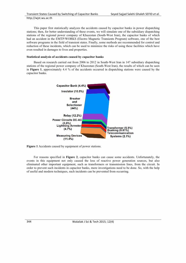
Based on research carried out from 2006 to 2012 in South-West Iran in 147 subsidiary dispatching stations of the regional power company of Khuzestan (South-West Iran), the results of which can be seen in Figure 1, approximately 4.4 % of the accidents occurred in dispatching stations were caused by the capacitor banks.
Figure 1 Accidents caused by equipment of power stations.
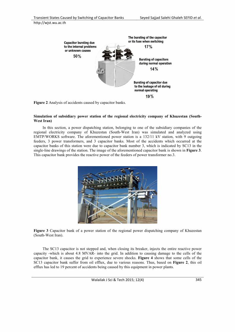
For reasons specified in Figure 2, capacitor banks can cause some accidents. Unfortunately, the
events in this equipment not only caused the loss of reactive power generation sources, but also eliminated other important equipment, such as transformers or transmission lines, from the circuit. In order to prevent such incidents in capacitor banks, more investigations need to be done. So, with the help of useful and modern techniques, such incidents can be prevented from occurring.
Transient States Caused by Switching of Capacitor Banks Seyed Sajjad Salehi Ghaleh SEFID et al. http://wjst.wu.ac.th
Walailak J Sci & Tech 2015; 12(4)
345
Figure 2 Analysis of accidents caused by capacitor banks. Simulation of subsidiary power station of the regional electricity company of Khuzestan (South-West Iran)
In this section, a power dispatching station, belonging to one of the subsidiary companies of the regional electricity company of Khuzestan (South-West Iran) was simulated and analyzed using EMTP/WORKS software. The aforementioned power station is a 132/11 kV station, with 9 outgoing feeders, 3 power transformers, and 3 capacitor banks. Most of the accidents which occurred at the capacitor banks of this station were due to capacitor bank number 3, which is indicated by SC13 in the single-line drawings of the station. The image of the aforementioned capacitor bank is shown in Figure 3. This capacitor bank provides the reactive power of the feeders of power transformer no.3.
Figure 3 Capacitor bank of a power station of the regional power dispatching company of Khuzestan (South-West Iran).
The SC13 capacitor is not stepped and, when closing its breaker, injects the entire reactive power capacity -which is about 4.8 MVAR- into the grid. In addition to causing damage to the cells of the capacitor bank, it causes the grid to experience severe shocks. Figure 4 shows that some cells of the SC13 capacitor bank suffer from oil efflux, due to various reasons. Thus, based on Figure 2, this oil efflux has led to 19 percent of accidents being caused by this equipment in power plants.

Transient States Caused by Switching of Capacitor Banks Seyed Sajjad Salehi Ghaleh SEFID et al. http://wjst.wu.ac.th
Walailak J Sci & Tech 2015; 12(4) 346
Figure 4 Oil efflux from the cells of SC13 capacitor bank.
Simulation of the station using EMTP / WORKS software is shown in Figure 5. Due to the high
volume of consumers, and the high length of its lines, all the feeders of power transformer no. 3 have been separately simulated in the mentioned software. Technical information associated with each cell of the SC13 capacitor bank and its breaker is presented in Tables 1 and 2.
Figure 5 Simulation of power dispatching station.
+
132kVRMSLL /_0
AC1
CP+400
TLM1
1 2
132/11
T1
1 2
132/11
T2
1 2
132/11
T3
12
315/
120
DY
_61
231
5/12
0
DY
_41
231
5/12
0
DY
_5CP+
400
301
CP+400
302
CP+400
303
CP+400
304
CP+400
305
CP+400
306
CP+400
307
CP+400
308
CP+400
309
PQ
1P
Q
1P
Q
2P
Q
3P
Q
3P
Q
3P
Q
1
LFSl
ack:
13.
8kVR
MSL
L/_0
LF1
LFSl
ack:
13.
8kVR
MSL
L/_0
LF2
LFSl
ack:
13.
8kVR
MSL
L/_0
LF3
+
1.7u
F
SC2
+
1.7u
F
SC1
+
1.7u
F
SC3
+1ms/10ms/0
SW2
+1ms/10ms/0
SW3
+1ms/10ms/0
SW1
PQ
2P
Q
2
BUS2
BUS3
BUS1
BUS0
Transient States Caused by Switching of Capacitor Banks Seyed Sajjad Salehi Ghaleh SEFID et al. http://wjst.wu.ac.th
Walailak J Sci & Tech 2015; 12(4)
347
Table 1 Technical specifications of the cells of capacitor bank.
Manufacturer's name Capacity of each cell (KVAR) Capacitance per cell (µf) Nominal voltage of each cell (KV) Number of cells in each phase
Sangamo 200 1.7 6.4 8
Table 2 Technical specifications of breaker of the capacitor bank.
Manufacturer's name Maximum rated current (A) Maximum nominal voltage (KV)
McGraw-Edison Company 400 15.4
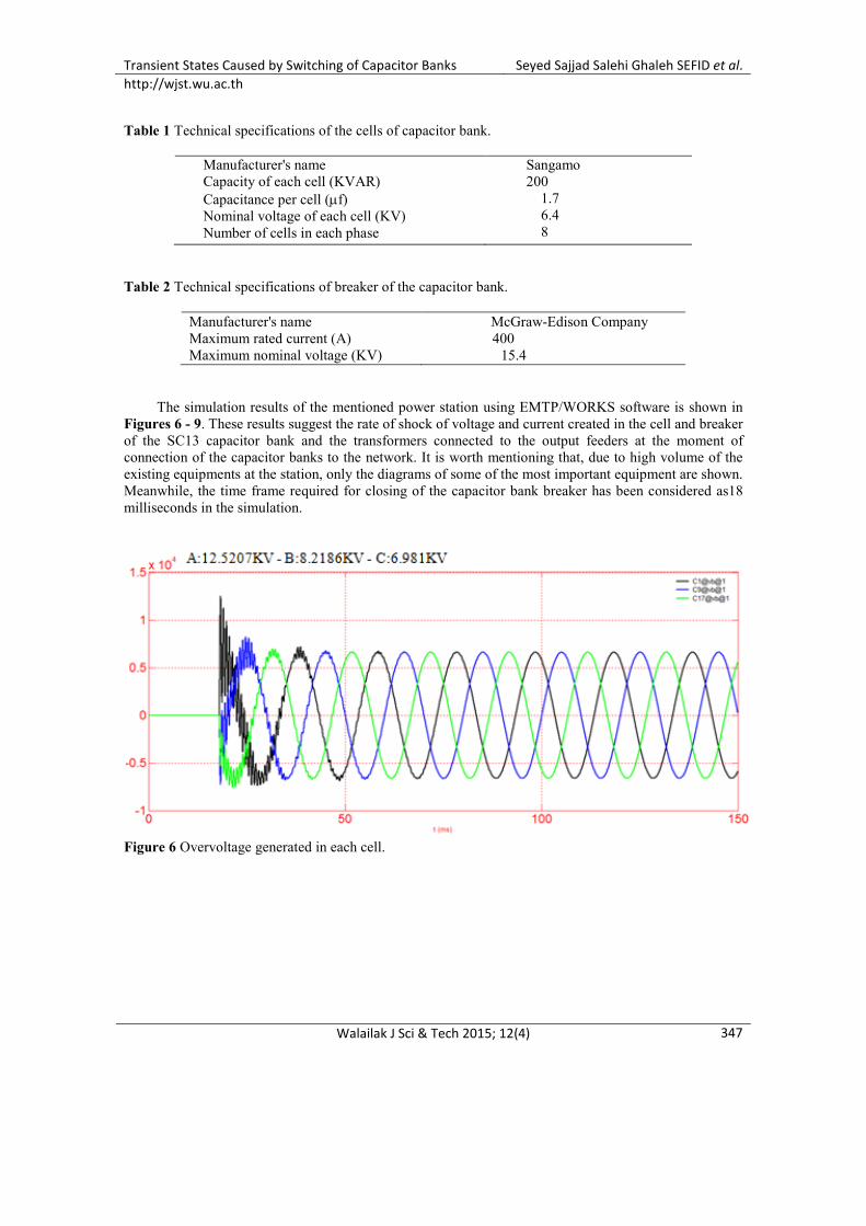
The simulation results of the mentioned power station using EMTP/WORKS software is shown in Figures 6 - 9. These results suggest the rate of shock of voltage and current created in the cell and breaker of the SC13 capacitor bank and the transformers connected to the output feeders at the moment of connection of the capacitor banks to the network. It is worth mentioning that, due to high volume of the existing equipments at the station, only the diagrams of some of the most important equipment are shown. Meanwhile, the time frame required for closing of the capacitor bank breaker has been considered as18 milliseconds in the simulation.
Figure 6 Overvoltage generated in each cell.
Transient States Caused by Switching of Capacitor Banks Seyed Sajjad Salehi Ghaleh SEFID et al. http://wjst.wu.ac.th
Walailak J Sci & Tech 2015; 12(4) 348
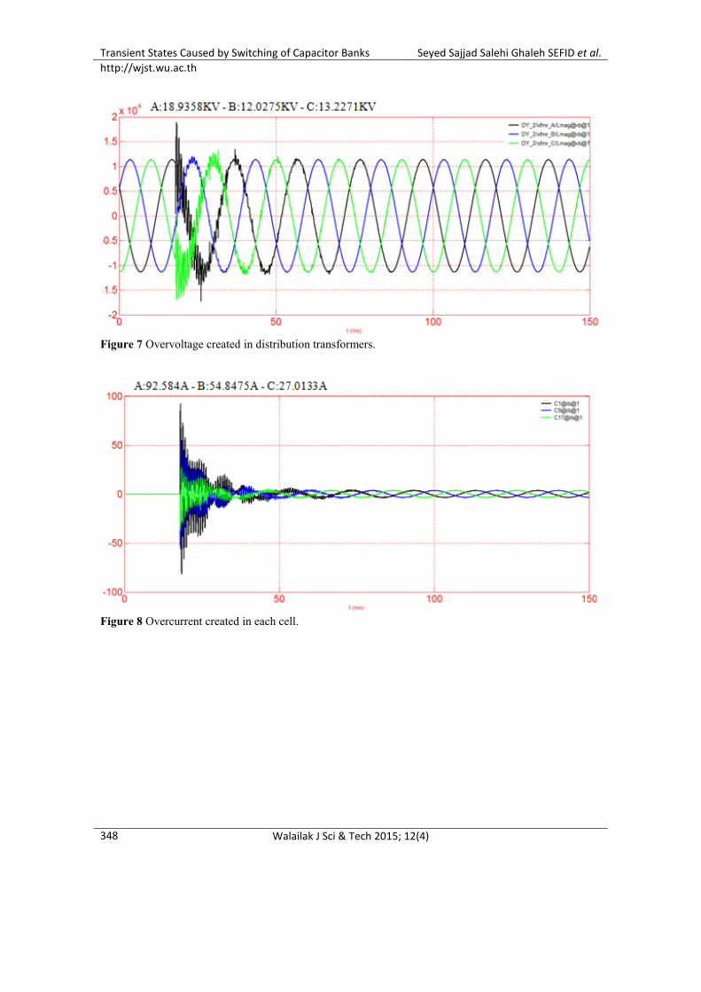
Figure 7 Overvoltage created in distribution transformers.
Figure 8 Overcurrent created in each cell.
Transient States Caused by Switching of Capacitor Banks Seyed Sajjad Salehi Ghaleh SEFID et al. http://wjst.wu.ac.th
Walailak J Sci & Tech 2015; 12(4)
349
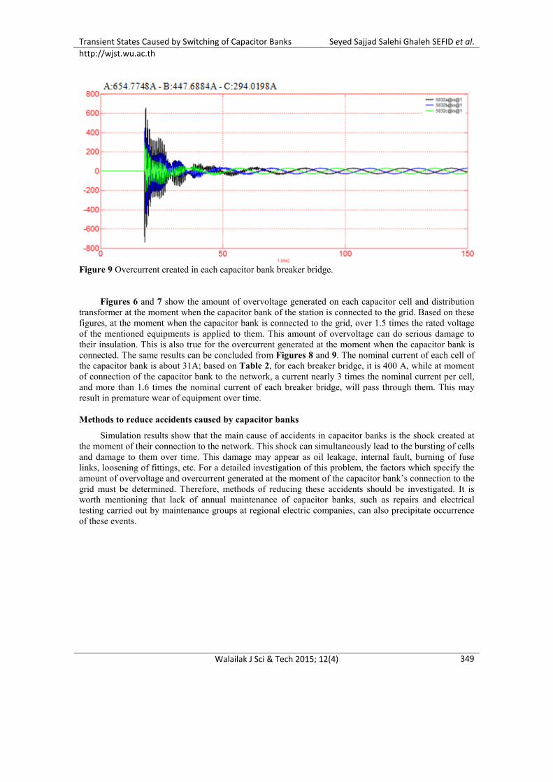
Figure 9 Overcurrent created in each capacitor bank breaker bridge.
Figures 6 and 7 show the amount of overvoltage generated on each capacitor cell and distribution transformer at the moment when the capacitor bank of the station is connected to the grid. Based on these figures, at the moment when the capacitor bank is connected to the grid, over 1.5 times the rated voltage of the mentioned equipments is applied to them. This amount of overvoltage can do serious damage to their insulation. This is also true for the overcurrent generated at the moment when the capacitor bank is connected. The same results can be concluded from Figures 8 and 9. The nominal current of each cell of the capacitor bank is about 31A; based on Table 2, for each breaker bridge, it is 400 A, while at moment of connection of the capacitor bank to the network, a current nearly 3 times the nominal current per cell, and more than 1.6 times the nominal current of each breaker bridge, will pass through them. This may result in premature wear of equipment over time. Methods to reduce accidents caused by capacitor banks
Simulation results show that the main cause of accidents in capacitor banks is the shock created at the moment of their connection to the network. This shock can simultaneously lead to the bursting of cells and damage to them over time. This damage may appear as oil leakage, internal fault, burning of fuse links, loosening of fittings, etc. For a detailed investigation of this problem, the factors which specify the amount of overvoltage and overcurrent generated at the moment of the capacitor bank’s connection to the grid must be determined. Therefore, methods of reducing these accidents should be investigated. It is worth mentioning that lack of annual maintenance of capacitor banks, such as repairs and electrical testing carried out by maintenance groups at regional electric companies, can also precipitate occurrence of these events.
Transient States Caused by Switching of Capacitor Banks Seyed Sajjad Salehi Ghaleh SEFID et al. http://wjst.wu.ac.th
Walailak J Sci & Tech 2015; 12(4) 350
Analysis of overvoltage and overcurrent caused by switching of capacitor banks
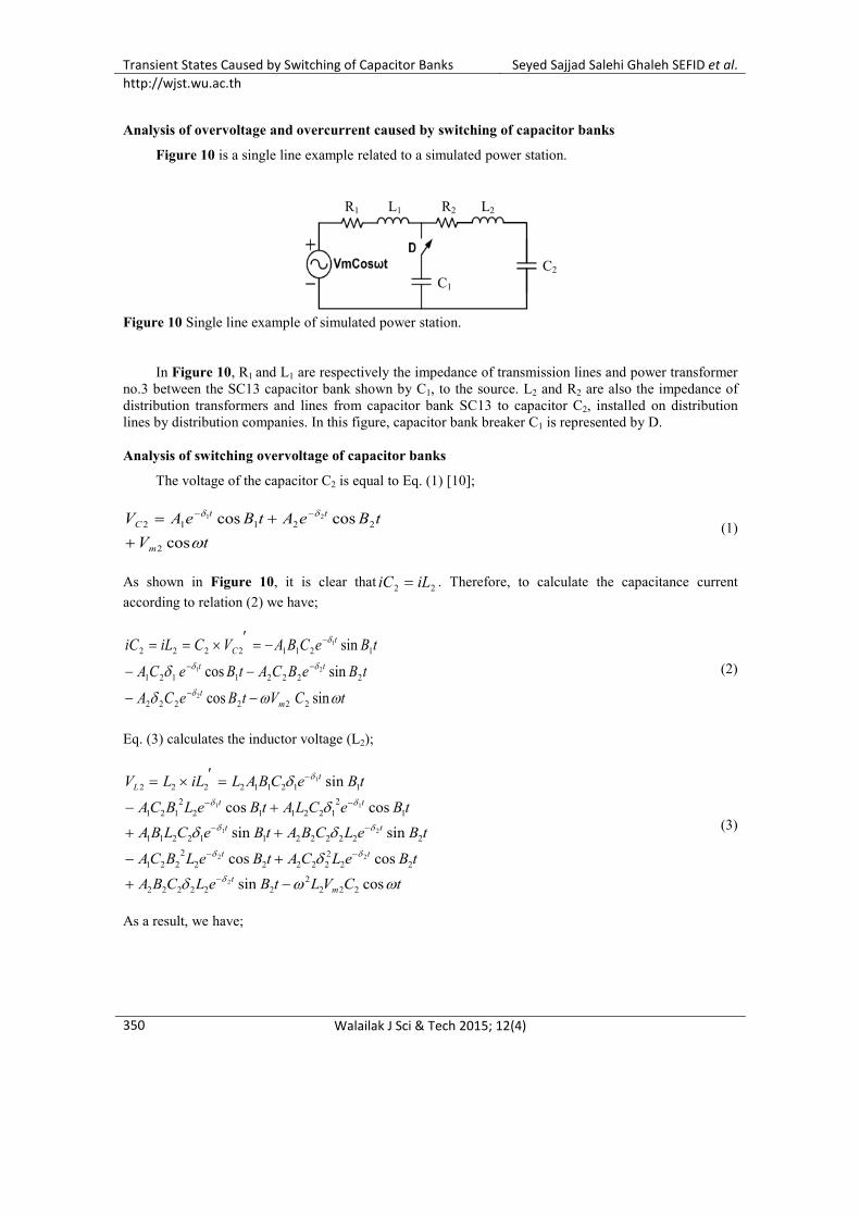
Figure 10 is a single line example related to a simulated power station.
Figure 10 Single line example of simulated power station.
In Figure 10, R1 and L1 are respectively the impedance of transmission lines and power transformer no.3 between the SC13 capacitor bank shown by C1, to the source. L2 and R2 are also the impedance of distribution transformers and lines from capacitor bank SC13 to capacitor C2, installed on distribution lines by distribution companies. In this figure, capacitor bank breaker C1 is represented by D. Analysis of switching overvoltage of capacitor banks
The voltage of the capacitor C2 is equal to Eq. (1) [10];
tVtBeAtBeAV
m
ttC
ω
δδ
coscoscos
2
2211221
++= −−
(1)
As shown in Figure 10, it is clear that 22 iLiC = . Therefore, to calculate the capacitance current according to relation (2) we have;
tCVtBeCAtBeBCAtBeCA
tBeCBAVCiLiC
mt
tt
tC
ωωδ
δδ
δδ
δ
sincos
sincos
sin
222222
22221121
12112222
2
21
1
−−
−−
−=′×==
−
−−
−
(2)
Eq. (3) calculates the inductor voltage (L2);
tCVLtBeLCBAtBeLCAtBeLBCA
tBeLCBAtBeCLBAtBeCLAtBeLBCA
tBeCBALiLLV
mt
tt
tt
tt
tL
ωωδ
δ
δδ
δ
δ
δ
δδ
δδ
δδ
δ
cossin
coscos
sinsin
coscos
sin
2222
222222
22222222
2221
222222112211
12
1221122
121
112112222
2
22
21
11
1
−+
+−
++
+−
=′×=
−
−−
−−
−−
−
(3)
As a result, we have;
C1 C2
R1 L1 R2 L2
Transient States Caused by Switching of Capacitor Banks Seyed Sajjad Salehi Ghaleh SEFID et al. http://wjst.wu.ac.th
Walailak J Sci & Tech 2015; 12(4)
351
tKtBeKtBeK
tBeKtBeKVtt
ttC
ω
δδ
δδ
coscoscos
coscos
5
22
411
3
22
211
11
+++
+=−−
−−
(4)
in which;
222
5
222224
122113
222222
222222
122
1212
12211
)1(
22
mVLKCLBAK
CLBAKALBCACLAK
ALBCACLAK
ω
δδ
δ
δ
−=
==
+−=
+−=
From Eq. (4), we conclude that the voltage value of capacitor C1, which represents the same
overvoltage of the SC13 capacitor bank at the moment of switching, depends on the distribution capacitances of C2 and the capacity of the distribution transformers. Analysis of switching overcurrent of capacitor banks
The current of capacitor C1 is given by Eq. (5);
tK
tBeKtBeK
tBeKtBeKiC
tt
tt
ω
δδ
δδ
sin
coscos
coscos
5
2413
22111
21
21
′+
′+
′+
′+
′=
−−
−−
(5)
In this equation;
155
12212441221242
11111331111131
CKK
CBKCKKCKCBKK
CBKCKKCKCBKK
ω
δδ
δδ
−=′
−−=′−=′
−−=′−=′
Eq. (5) indicates that the current of capacitor bank SC13 at the moment of switching depends on the
capacities of the capacitors. According to the instructions of Iranian Ministry of Power, electrical power distribution companies
are free to determine the capacity of transformers and capacitors installed in their distribution network, and the regional power companies responsible for the maintenance and operation of dispatching stations can only install capacitor banks in power plants, considering the required network capacity. Accordingly, by reducing the capacity of the installed capacitors and transformers in the distribution network, we cannot actually reduce the peak voltage shock of the capacitor banks in power plants, which is dependent on these two, and other methods should be used, which will be discussed in the following section.
Transient States Caused by Switching of Capacitor Banks Seyed Sajjad Salehi Ghaleh SEFID et al. http://wjst.wu.ac.th
Walailak J Sci & Tech 2015; 12(4) 352
Proposed methods to reduce accidents caused by capacitor banks
Connection of capacitor banks to the network at the zero voltage moment When a capacitor with no load is stimulated, the system voltage drops instantaneously (because the
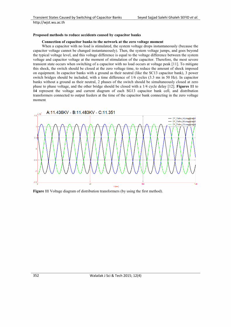
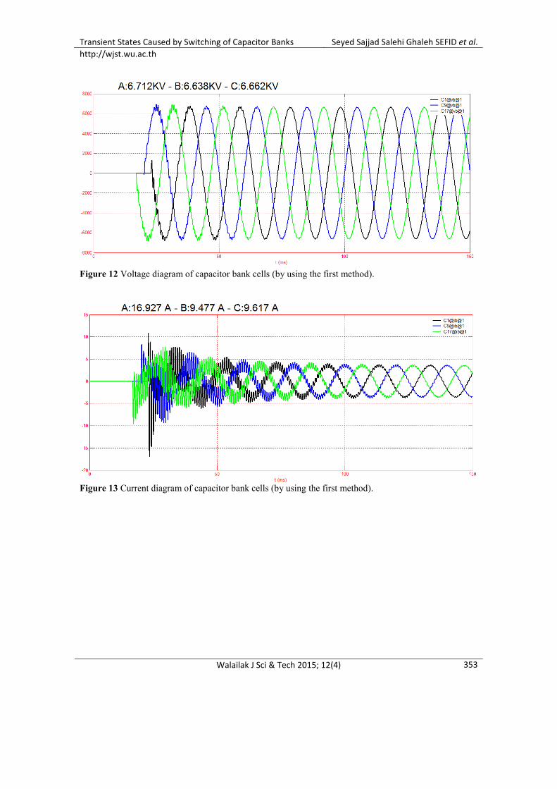
capacitor voltage cannot be changed instantaneously). Then, the system voltage jumps, and goes beyond the typical voltage level, and this voltage difference is equal to the voltage difference between the system voltage and capacitor voltage at the moment of stimulation of the capacitor. Therefore, the most severe transient state occurs when switching of a capacitor with no load occurs at voltage peak [11]. To mitigate this shock, the switch should be closed at the zero voltage time, to reduce the amount of shock imposed on equipment. In capacitor banks with a ground as their neutral (like the SC13 capacitor bank), 3 power switch bridges should be included, with a time difference of 1/6 cycles (3.3 ms in 50 Hz). In capacitor banks without a ground as their neutral, 2 phases of the switch should be simultaneously closed at zero phase to phase voltage, and the other bridge should be closed with a 1/4 cycle delay [12]. Figures 11 to 14 represent the voltage and current diagram of each SG13 capacitor bank cell, and distribution transformers connected to output feeders at the time of the capacitor bank connecting in the zero voltage moment.
Figure 11 Voltage diagram of distribution transformers (by using the first method).
Transient States Caused by Switching of Capacitor Banks Seyed Sajjad Salehi Ghaleh SEFID et al. http://wjst.wu.ac.th
Walailak J Sci & Tech 2015; 12(4)
353
Figure 12 Voltage diagram of capacitor bank cells (by using the first method).
Figure 13 Current diagram of capacitor bank cells (by using the first method).
Transient States Caused by Switching of Capacitor Banks Seyed Sajjad Salehi Ghaleh SEFID et al. http://wjst.wu.ac.th
Walailak J Sci & Tech 2015; 12(4) 354
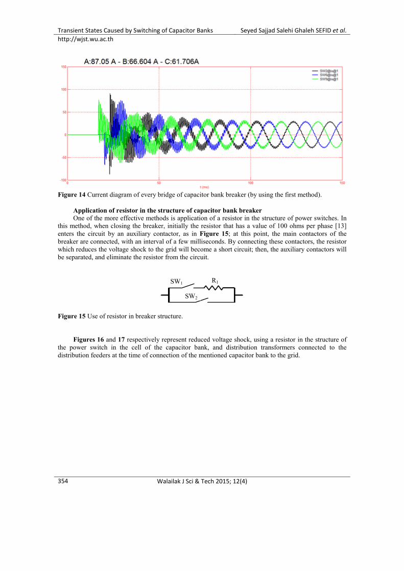
Figure 14 Current diagram of every bridge of capacitor bank breaker (by using the first method).
Application of resistor in the structure of capacitor bank breaker One of the more effective methods is application of a resistor in the structure of power switches. In
this method, when closing the breaker, initially the resistor that has a value of 100 ohms per phase [13] enters the circuit by an auxiliary contactor, as in Figure 15; at this point, the main contactors of the breaker are connected, with an interval of a few milliseconds. By connecting these contactors, the resistor which reduces the voltage shock to the grid will become a short circuit; then, the auxiliary contactors will be separated, and eliminate the resistor from the circuit.
Figure 15 Use of resistor in breaker structure.
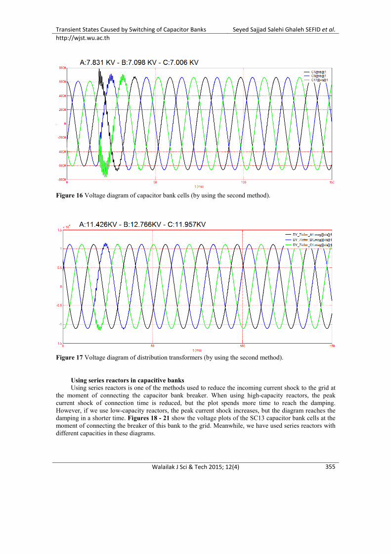
Figures 16 and 17 respectively represent reduced voltage shock, using a resistor in the structure of the power switch in the cell of the capacitor bank, and distribution transformers connected to the distribution feeders at the time of connection of the mentioned capacitor bank to the grid.
R1 SW1
SW2
Transient States Caused by Switching of Capacitor Banks Seyed Sajjad Salehi Ghaleh SEFID et al. http://wjst.wu.ac.th
Walailak J Sci & Tech 2015; 12(4)
355
Figure 16 Voltage diagram of capacitor bank cells (by using the second method).
Figure 17 Voltage diagram of distribution transformers (by using the second method).
Using series reactors in capacitive banks Using series reactors is one of the methods used to reduce the incoming current shock to the grid at
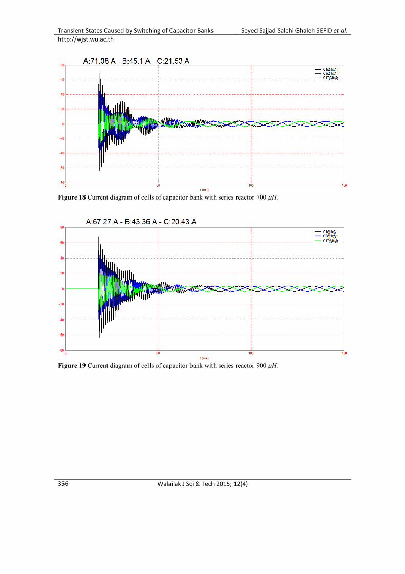
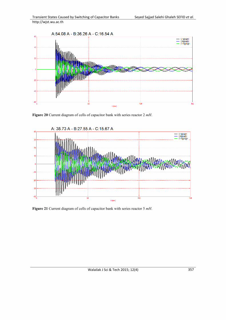
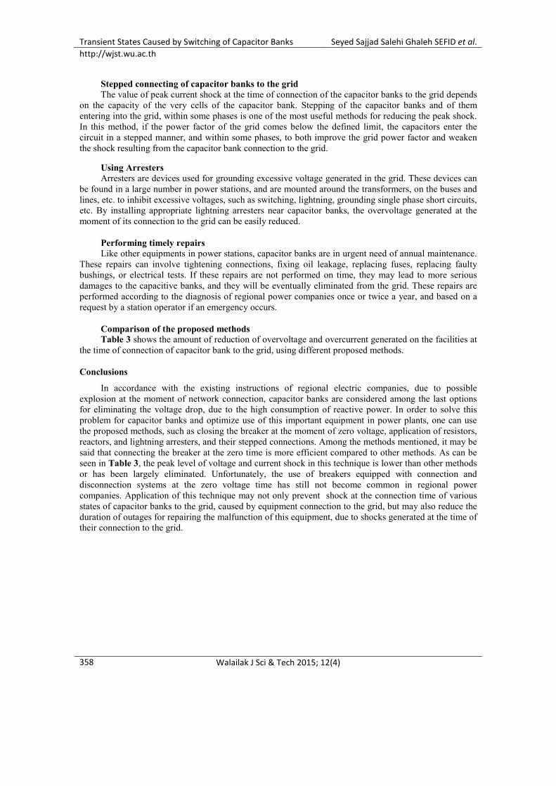
the moment of connecting the capacitor bank breaker. When using high-capacity reactors, the peak current shock of connection time is reduced, but the plot spends more time to reach the damping. However, if we use low-capacity reactors, the peak current shock increases, but the diagram reaches the damping in a shorter time. Figures 18 - 21 show the voltage plots of the SC13 capacitor bank cells at the moment of connecting the breaker of this bank to the grid. Meanwhile, we have used series reactors with different capacities in these diagrams.
Transient States Caused by Switching of Capacitor Banks Seyed Sajjad Salehi Ghaleh SEFID et al. http://wjst.wu.ac.th
Walailak J Sci & Tech 2015; 12(4) 356
Figure 18 Current diagram of cells of capacitor bank with series reactor 700 µH.
Figure 19 Current diagram of cells of capacitor bank with series reactor 900 µH.
Transient States Caused by Switching of Capacitor Banks Seyed Sajjad Salehi Ghaleh SEFID et al. http://wjst.wu.ac.th
Walailak J Sci & Tech 2015; 12(4)
357
Figure 20 Current diagram of cells of capacitor bank with series reactor 2 mH.
Figure 21 Current diagram of cells of capacitor bank with series reactor 5 mH.
Transient States Caused by Switching of Capacitor Banks Seyed Sajjad Salehi Ghaleh SEFID et al. http://wjst.wu.ac.th
Walailak J Sci & Tech 2015; 12(4) 358
Stepped connecting of capacitor banks to the grid The value of peak current shock at the time of connection of the capacitor banks to the grid depends
on the capacity of the very cells of the capacitor bank. Stepping of the capacitor banks and of them entering into the grid, within some phases is one of the most useful methods for reducing the peak shock. In this method, if the power factor of the grid comes below the defined limit, the capacitors enter the circuit in a stepped manner, and within some phases, to both improve the grid power factor and weaken the shock resulting from the capacitor bank connection to the grid.
Using Arresters Arresters are devices used for grounding excessive voltage generated in the grid. These devices can
be found in a large number in power stations, and are mounted around the transformers, on the buses and lines, etc. to inhibit excessive voltages, such as switching, lightning, grounding single phase short circuits, etc. By installing appropriate lightning arresters near capacitor banks, the overvoltage generated at the moment of its connection to the grid can be easily reduced.
Performing timely repairs Like other equipments in power stations, capacitor banks are in urgent need of annual maintenance.
These repairs can involve tightening connections, fixing oil leakage, replacing fuses, replacing faulty bushings, or electrical tests. If these repairs are not performed on time, they may lead to more serious damages to the capacitive banks, and they will be eventually eliminated from the grid. These repairs are performed according to the diagnosis of regional power companies once or twice a year, and based on a request by a station operator if an emergency occurs.
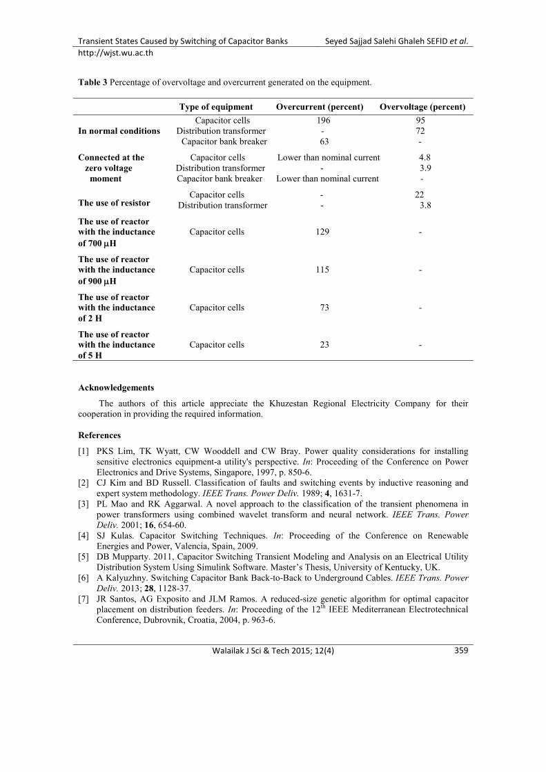
Comparison of the proposed methods Table 3 shows the amount of reduction of overvoltage and overcurrent generated on the facilities at
the time of connection of capacitor bank to the grid, using different proposed methods. Conclusions
In accordance with the existing instructions of regional electric companies, due to possible explosion at the moment of network connection, capacitor banks are considered among the last options for eliminating the voltage drop, due to the high consumption of reactive power. In order to solve this problem for capacitor banks and optimize use of this important equipment in power plants, one can use the proposed methods, such as closing the breaker at the moment of zero voltage, application of resistors, reactors, and lightning arresters, and their stepped connections. Among the methods mentioned, it may be said that connecting the breaker at the zero time is more efficient compared to other methods. As can be seen in Table 3, the peak level of voltage and current shock in this technique is lower than other methods or has been largely eliminated. Unfortunately, the use of breakers equipped with connection and disconnection systems at the zero voltage time has still not become common in regional power companies. Application of this technique may not only prevent shock at the connection time of various states of capacitor banks to the grid, caused by equipment connection to the grid, but may also reduce the duration of outages for repairing the malfunction of this equipment, due to shocks generated at the time of their connection to the grid.
Transient States Caused by Switching of Capacitor Banks Seyed Sajjad Salehi Ghaleh SEFID et al. http://wjst.wu.ac.th
Walailak J Sci & Tech 2015; 12(4)
359
Table 3 Percentage of overvoltage and overcurrent generated on the equipment. Type of equipment Overcurrent (percent) Overvoltage (percent) Capacitor cells 196 95 In normal conditions Distribution transformer - 72 Capacitor bank breaker 63 -
Connected at the Capacitor cells Lower than nominal current 4.8 zero voltage Distribution transformer - 3.9 moment Capacitor bank breaker Lower than nominal current -
The use of resistor Capacitor cells - 22 Distribution transformer - 3.8
The use of reactor with the inductance Capacitor cells 129 - of 700 µH
The use of reactor with the inductance Capacitor cells 115 - of 900 µH
The use of reactor with the inductance Capacitor cells 73 - of 2 H
The use of reactor with the inductance Capacitor cells 23 - of 5 H Acknowledgements
The authors of this article appreciate the Khuzestan Regional Electricity Company for their cooperation in providing the required information.
References
[1] PKS Lim, TK Wyatt, CW Wooddell and CW Bray. Power quality considerations for installing sensitive electronics equipment-a utility's perspective. In: Proceeding of the Conference on Power Electronics and Drive Systems, Singapore, 1997, p. 850-6.
[2] CJ Kim and BD Russell. Classification of faults and switching events by inductive reasoning and expert system methodology. IEEE Trans. Power Deliv. 1989; 4, 1631-7.
[3] PL Mao and RK Aggarwal. A novel approach to the classification of the transient phenomena in power transformers using combined wavelet transform and neural network. IEEE Trans. Power Deliv. 2001; 16, 654-60.
[4] SJ Kulas. Capacitor Switching Techniques. In: Proceeding of the Conference on Renewable Energies and Power, Valencia, Spain, 2009.
[5] DB Mupparty. 2011, Capacitor Switching Transient Modeling and Analysis on an Electrical Utility Distribution System Using Simulink Software. Master’s Thesis, University of Kentucky, UK.
[6] A Kalyuzhny. Switching Capacitor Bank Back-to-Back to Underground Cables. IEEE Trans. Power Deliv. 2013; 28, 1128-37.
[7] JR Santos, AG Exposito and JLM Ramos. A reduced-size genetic algorithm for optimal capacitor placement on distribution feeders. In: Proceeding of the 12th IEEE Mediterranean Electrotechnical Conference, Dubrovnik, Croatia, 2004, p. 963-6.
Transient States Caused by Switching of Capacitor Banks Seyed Sajjad Salehi Ghaleh SEFID et al. http://wjst.wu.ac.th
Walailak J Sci & Tech 2015; 12(4) 360
[8] A Bidram, M Hamedani-Golshan and A Davoudi. Capacitor design considering first swing stability of distributed generation. IEEE Trans. Power Syst. 2012; 27, 1941-8.
[9] C Guillermin, O Dujeu and JM Lupin. Metallized film power capacitors end-of-life study through monitored destruction tests. IEEE Trans. Power Deliv. 2013; 28, 368-75.
[10] A Kalyuzhny, S Zissu and D Shein. Analytical study of voltage magnification transients due to capacitor switching. IEEE Trans. Power Deliv. 2009; 24, 797-805.
[11] TA Short. Electric Power Distribution Handbook. CRC Press, New York, 2003, p. 543-51. [12] RW Alexander. Synchronous closing control for shunt capacitors. IEEE Trans. Power Apparatus
Syst. 1985; 104, 2619-26. [13] TE Grebe and EW Gunther. Application of the EMTP for analysis of utility capacitor switching
mitigation techniques. In: Proceeding of the 8th International Conference on Harmonics and Quality of Power, Athens, Greece, 1998, p. 583-9.