Embed Size (px)
Citation preview

1. Introduction
Short glass fiber (GF) polymer matrix composites
(PMC) with 30–50 wt% fiber loading have been
widely used in automotive and marine industries as
structural components due to their high specific
strength and stiffness. Continued development in
light-weighted PMC with higher mechanical per-
formance has been fueled by the premise that 10%
reduction in the vehicle weight can result in 6–8%
increase in fuel efficiency [1]. One approach towards
light weighting is the incorporation of nanoparticles
either as a reinforcement phase within the matrix
polymer, or at the fiber/matrix interface [2–5]. The
high surface area per unit volume of nanoparticles
enhances the interactions with the other constituents
in the composite and subsequently enhances the me-
chanical properties compared to larger dimension par-
ticles of the same composition [6]. However, issues
such as inhomogeneous dispersion and agglomerate
formation should be addressed before using these
materials in large scale production of composites.
Alternative nanoparticles that have potential for in-
creasing GF-polymer matrix composites properties
are cellulose nanomaterials (CNs). CNs are cellu-
lose-based nanoparticles that are obtained from
plants, algae, bacteria and marine animals [7–9]. CN
particles are generally grouped based on the cellulose
source and the extraction methods, leading to various
CN types, including: cellulose nanocrystals (CNC),
cellulose nanofibrils (CNF), algae cellulose (AC),
bacterial cellulose (BC), etc. One common trait with
all CN types is the parallel stacking of cellulose
587
Improving the interfacial and mechanical properties of
short glass fiber/epoxy composites by coating the glass fibers
with cellulose nanocrystals
A. Asadi1, M. Miller1, R. J. Moon2,3, K. Kalaitzidou1,3*
1G.W. Woodruff School of Mechanical Engineering – Georgia Institute of Technology, GA 30332 Atlanta, United States2The Forest Products Laboratory, U.S. Forest Service, Madison, 53726 Wisconsin, United States3School of Materials Science and Engineering – Georgia Institute of Technology, GA 30332 Atlanta, United States
Received 11 December 2015; accepted in revised form 11 February 2016
Abstract. In this study, the interfacial and mechanical properties of cellulose nanocrystals (CNC) coated glass fiber/epoxy
composites were investigated as a function of the CNC content on the surface of glass fibers (GF). Chopped GF rovings
were coated with CNC by immersing the GF in CNC (0–5 wt%) aqueous suspensions. Single fiber fragmentation (SFF)
tests showed that the interfacial shear strength (IFSS) increased by ~69% in composites produced with CNC coated GF as
compared to uncoated GF, suggesting an enhancement of stress transfer across the GF/matrix interface. The role of CNC
coatings on the tensile, flexural, and thermo-mechanical properties of the CNC-coated GF/epoxy composites was investigated.
Incorporation of 0.17 wt% CNC in the composite resulted in increases of ~10% in both elastic modulus and tensile strength,
and 40 and 43 % in flexural modulus and strength respectively. In conclusion CNC coatings on GF alter the GF/matrix
interface resulting in improvement of the mechanical performance of the corresponding composites.
Keywords: polymer composites, nanomaterials, coatings, mechanical properties
eXPRESS Polymer Letters Vol.10, No.7 (2016) 587–597
Available online at www.expresspolymlett.com
DOI: 10.3144/expresspolymlett.2016.54
*Corresponding author, e-mail: [email protected]
© BME-PT

chains along the particle length, and because of this
feature the properties of the various CNs are similar
to each other, at least within the scatter of experi-
mental testing or atomistic model predictions [9].
With this in mind, as a whole CNs have a unique com-
bination of characteristics [9] that make them attrac-
tive for certain composite applications, i.e. low den-
sity (1.6 g/cm3), high surface area and aspect ratio
(10–100), tensile strength of 3–7.5 GPa, and elastic
modulus of 110–220 GPa, surfaces with accessible
hydroxyl side groups (e.g. –OH) that can be readily
chemically modified, and low toxicity [10]. In addi-
tion, CNs extracted from trees and plants have the
potential to be produced at industrial scale quantities,
and reasonable price [11]. In the current study, the CN
type used was CNC, which are whisker-shaped par-
ticles (typically, 3–5 nm in width and 5–500 nm in
length), extracted by acid hydrolysis of plants [12],
and are considered to have properties within the
ranges listed above.
There has been considerable interest in CNs as rein-
forcement in various polymer systems due to their
high specific modulus and strength characteristics,
and provided that the CNs are well dispersed within
the polymer matrix, increases in mechanical perform-
ance of the CN-polymer system and subsequently the
corresponding composites can be expected. For most
epoxy systems, obtaining well dispersed CNs in
epoxies has been exceedingly challenging, especially
for high CN volume fraction [13–20]. To address this
issues, waterborne epoxies [14, 15, 18], solvent ex-
change methods [20, 21], CN preforms impregnation
[22] and chemical modification of CN surfaces have
been used [23], however, the time and cost involved
in these processes limit their capability in industrial
scale production of GF/epoxy composites.
An alternative approach has been to add CNs to GF/
epoxy composites by coating the GF prior to mixing
into epoxy, where the CN coating modifies the GF/
epoxy interface and subsequently improves the prop-
erties. A good review on tailoring interphase through
coating the fibers in polymer composites can be
found in [24]. Chen et al. [25] deposited bacterial cel-
lulose (BC) on the surface of GF during the process
of fermentation. The BC coated GF were subsequent-
ly compounded into epoxy, where the increase in the
interfacial shear strength (IFSS) of BC coated GF/
epoxy interface was attributed to the increase in in-
terfacial surface roughness and area, and chemical
bonding between the BC coating and the epoxy ma-
trix. However, for large volume uses, growth of the
BC film on GF is impractical. Additional work is need-
ed to i) find coating processes that are quick, reli-
able, and inexpensive and ii) link changes in IFSS to
differences in macroscopic mechanical properties of
the GF/epoxy composites as a result of the addition
of the CN coatings. To the best of the authors’ knowl-
edge, no studies exist on simple coating technique
of GF with CN and the influence of the CN coating
on both the interfacial and mechanical properties.
In this study, the effect of CNC coatings on GF on
the GF/epoxy matrix interfacial properties and the
subsequent influence on the mechanical properties
of short GF/epoxy composites are investigated. GF
were coated by immersing them in an aqueous CNC
suspension (0–5 wt%), a scalable technique. Interfa-
cial adhesion was characterized by the IFSS using
single fiber fragmentation tests (SFF). Changes in the
IFSS and stiffness across the GF/matrix interphase
as a result of CNC coating on the GF were two po-
tential mechanisms considered for the enhancement
in tensile and flexural properties of CNC coated-
GF/epoxy composites. The optimum CNC concen-
tration on the GF that resulted in the best mechanical
performance was determined.
2. Experimental details
2.1. Materials
Owens Corning (Oak Brook, IL, US) ME1510 multi-
end roving GF (TEX 48000, single filament diame-
ter of 10±1 µm) were used as received. The GF rov-
ings were chopped to an average length of 25±0.5 mm.
A bicomponent epoxy resin consisting of 635 thin
epoxy and 556 slow amine hardener supplied by US
Composites (West Palm Beach, FL) was used. CNC
in the form of 11.9 wt% never-dried suspension in
water [26] were supplied by the USDA Forest Serv-
ice-Forest Products Laboratory (FPL), Madison, WI,
USA. The average length and width of the CNC
were 138±22 nm and 6.4±0.6, respectively [18].
2.2. Coating of GF with CNC and fabrication
of CNC-coated GF/epoxy composites
CNC coated GF were produced by immersing ~154 g
of chopped GF rovings in ~1000 mL of aqueous CNC
suspension without agitation for 2 min, after which
the GF were taken out and spread on covered trays
with ample ventilation to dry 24 h at room tempera-
ture. This simple, low cost coating method is concep-
tually scalable for larger volume applications. The
Asadi et al. – eXPRESS Polymer Letters Vol.10, No.7 (2016) 587–597
588

CNC used were not functionalized or surface treated.
For uncoated GF, a similar procedure was followed
using distilled water with no CNC to maintain the
consistency in fabrication. The CNC suspension was
diluted, in order to adjust the CNC coating, using dis-
tilled water and then sonicated to achieve a uniform
CNC dispersion in water. Sonication was carried out
using Misonix S-4000 ultrasonic processor equipped
with a 12.5 mm probe diameter at 30% amplitude
and 20 W power for 8 min. Aqueous CNC suspen-
sions of 0, 0.5, 1, 1.5, 2, 3 and 5 wt%, were prepared
using the above procedure and used to coat the
chopped GF rovings. The corresponding naming
scheme used to describe the coated fibers is GF, 0.5S-
GF, 1S-GF, 1.5S-GF, 2S-GF, 3S-GF, and 5S-GF, re-
spectively. The ‘S’ in this case represents the con-
centration of CNC suspension.
For SFF test specimen preparation, individual GF fil-
aments were carefully pulled off from the coated and
uncoated GF rovings. Subsequently, a single 120 mm
long GF filament was placed in the middle of a dog-
bone shaped mold and covered with epoxy resin that
was cured at 80°C for 1 h, followed by post-curing
at 100°C for 4 h. Prior to pour the epoxy in the mold,
the single GF filaments were manually pre-strained
and the ends of the GF were taped down to ensure
that the GF remain in tension during the epoxy curing.
The resin was prepared by mixing the epoxy with
hardener at 2:1 wt% using a VWR magnetic stirring
plate at a 60 rpm, at room temperature for 10 min, and
was degassed in a vacuum chamber for 5 min prior to
pouring into the mold. SFF test specimens were pre-
pared using the following GF: GF, 0.5S-GF, 1S-GF,
1.5S-GF, 2S-GF, 3S-GF, and 5S-GF. The SFF test dog-
bone specimens were made according to the test pro-
tocol for SFF test [27], having a gauge length of
25 mm long, 3 mm wide and a depth of 2 mm, with an
overall length and width of 80 and 10 mm, respec-
tively.
GF/epoxy composites were produced with a 30 wt%
GF content. Chopped GF rovings with or without
CNC coatings were added and mixed with the resin
using a spatula in a tote and degassed in a vacuum
chamber, for 5 min. Then, the mixture was spread in
a rectangular mold and cured as described above.
Based on the SFF results (see Section 3.2), only 1S-
GF, 1.5S-GF and 2S-GF were used to make CNC-
GF/epoxy composites. The test coupons were cut
from the plate using a waterjet (MAXIEM 1515).
2.3. Characterization techniques
2.3.1. Single-fiber fragmentation tests (SFF)
SFF tests, as described by Hunston et al. [27], were
used to quantify the effect of CNC coatings on the
IFSS. In brief, tensile tests, with applied load along
the fiber axis direction, were carried out at a dis-
placement rate of 1 mm/min using an Instron 33R
4466 equipped with a 500 N load cell. The tests con-
tinued until the load passed its peak and dropped at
90–95% of maximum load to ensure that no further
fiber fragmentation could occur. Since the GF were
pre-strained, it was expected that when the epoxy
reached at its strain to failure, saturation in the GF
fragmentation had occurred. It is noted that if the test
continued further than this point, the samples would
break into two pieces and the fragmentation lengths
could not be recorded. The IFSS was determined by
Kelly and Tyson model [28] given in Equation (1):
(1)
where τi is the IFSS, df is the fiber diameter, lc is the
fiber critical fragmentation length, l–
is the average
length of fiber fragmentation segments (lc = 4l–/3)
and σf is the fiber strength at the critical length. The
fiber diameter and fiber fragmentation lengths were
measured using polarized microscopy. The GF fiber
strength was estimated by tensile testing (ASTM
D3822), where a single GF fiber was attached to a
paper tab and tested at a displacement rate of
1 mm/min using the Instron. An average GF strength
of 2900±350 MPa was measured for a gauge length
of 25.4 mm and as expected, the CNC coating process
did not affect the single GF ultimate strength. Both
the strength value and the IFSS values reported are
an average of at least 10 measurements. Weibull dis-
tribution was applied for the GF strength data [29]
to obtain the Weibull modulus and fiber strength as
4.57 and 2900 MPa respectively. These values were
used to extrapolate the GF strength at the critical
length required in Equation (1).
2.3.2. Microscopy
A Leica DM2500 polarized light optical microscope
was used to characterize CNC coatings on chopped
GF rovings, and to measure the fiber fragmentation
lengths in SFF tests. A Hitachi SU 8230 field emis-
sion scanning electron microscope (FE-SEM) at an
acceleration of 5 kV were used to view the CNC coat-
l
d l
l
d l
2 8
3ic
f f c f f cxv v= =Q QV V
Asadi et al. – eXPRESS Polymer Letters Vol.10, No.7 (2016) 587–597
589
ings on individual GF, and the fracture surfaces of the
composites. A plasma sputter (Ted Pella Inc.) was
used to apply gold coating on the surface of the sam-
ples prior to SEM imaging to minimize charging.
2.3.3. Specific density, thermal stability and
CNC content
Water displacement method was used to measure the
specific density of the composites according to ASTM
D-792. Thermogravimetry analysis (TGA), using
TGA SDT Q600 (TA Instruments), was used to as-
sess the thermal stability of CNC and determine the
CNC content on the GF. The samples were heated
from 50 to 500 °C at 10°C/min in inert atmosphere.
Each data point is an average of at least 3 measure-
ments.
2.3.4. Mechanical and dynamic mechanical
testing
The tensile properties of the composites were deter-
mined according to ASTM D638 using an Instron
33R 4466 equipped with 10 kN load cell. An exten-
someter, Instron 2630-35, with a gauge length of
50.8 mm was used. The modulus was calculated be-
tween the axial strain values of 0.05 and 0.2%. Each
tensile data point is an average of at least five sam-
ples. The flexural properties were measured using
three-point bending tests with an Instron 33R 4466
equipped with 10 kN load cell according to ASTM
D790-02 with a support span of 50 mm and a sample
thickness of 5 mm at a displacement rate of
0.85 mm/min. Each flexural data point is an average
of at least seven tests. Dynamic mechanical thermal
analyses (DMA Q800, TA Instruments) in three-point
bending mode was used to measure the storage and
loss moduli and the glass transition temperature (Tg)
in the 25–160°C range at a heating rate of 5 °C /min
and 1 Hz. A preload of 0.01 N and a maximum strain
of 0.05% were applied on the specimens. Each data
point is an average of at least five tests.
3. Results and discussion
In order to test the hypothesis that addition of CNC
on the GF/epoxy interphase can improve the me-
chanical properties of the composites, composites
with uncoated and CNC coated GF were compared
in terms of mechanical properties. First, it was de-
termined whether or not the CNC alter the GF/epoxy
interphase (a region around the GF in which the me-
chanical properties differ from the bulk mechanical
properties of the composite) and the optimum CNC
concentration needed to increase the properties of
the composites with no weight penalty.
3.1. CNC coatings on GF
GF rovings were coated with CNC according to the
process described in Section 2.2. As shown in Fig-
ure 1a, 1b, a thin layer of CNC is deposited on the
GF surface as a result of physical absorption (e.g.
hydrogen bonding of the accessible –OH side groups
on the CNC surface as described in Chen et al. [25]).
Of interest is how the CNC coated the chopped GF
rovings, as well as individual GF within the rovings.
To observe the surface of individual GF, the GF were
pulled out from the chopped GF rovings after the
coating process. As shown in Figure 1c–e, the un-
coated GF has a smooth surface, while the surface of
CNC coated GF is rougher, indicating that CNC
have been deposited on the GF surface. Additionally,
the coated GF surface roughness appears to increase
with the CNC coating deposition concentration, sug-
gesting that more CNC are deposited on the GF sur-
face. Some of the roughness features in the CNC coat-
ing on individual GF is likely associated with the
CNC coating process using the GF rovings as opposed
to individual GF, in which GF-GF meniscus forma-
tion within GF rovings during drying would cause
deposition variations. In addition, deformation of the
CNC coating would occur when separating GF from
other GF within the GF roving.
The implications of these observations are that al-
though GF rovings are used in the coating process,
the CNC suspension can penetrate the GF rovings
and coat individual GF. The differences in the GF sur-
face roughness of individual GF may subsequently
alter the stress transfer efficiency at the GF/epoxy in-
terphase in SFF testing that uses individual GF, as
seen in Section 3.2, but it is unclear to what extent,
roughness will influence the results of the compos-
ites testing where much larger-sized chopped GF
rovings are used.
3.2. Interfacial properties
Figure 2a shows an optical image of a post-tested
SFF 0.5S-GF test coupon with three fracture events
along the GF, where the distance between each frac-
ture represents an individual fiber fragment length.
The average fiber critical length (= 4l–/3, where is
the average of several individual fiber fragment
lengths), and the calculated IFSS, as a function of
Asadi et al. – eXPRESS Polymer Letters Vol.10, No.7 (2016) 587–597
590

CNC coating concentration on the GF surface are
shown in Figure 2b. Changes in both the IFSS and
fiber critical length when the GF are coated indicate
that the load transfer across the GF/CNC/epoxy in-
terphase has been modified. Possible mechanism are
mechanical interlocking between the GF and epoxy
due to the increased GF surface roughness and cor-
responding increased surface area, as well as differ-
ent chemical affinity as a result of the GF having a
CNC coating. There appears to be an optimum con-
dition i.e. 1S-GF for which the IFSS reaches a max-
imum, that corresponds to ~69% increase compared
to that of the uncoated GF/epoxy specimen. As the
concentration of CNC suspension increases, i.e. for
1.5S-GF, 2S-GF, 3S-GF, and 5S-GF SFF cases, there
is a reduction in IFSS. The lower IFSS suggest that
Asadi et al. – eXPRESS Polymer Letters Vol.10, No.7 (2016) 587–597
591
Figure 1. Polarized micrographs (polarized light of 95°) of chopped GF rovings, (a) uncoated, and (b) coated 1.5S-GF; SEM
images of single GF coated with CNC (c) 0 wt%, (d) 1 wt % and (e) 5 wt% suspensions

the CNC coatings have reduced the stress transfer
efficiency at the GF/CNC/epoxy interphase. A few
mechanisms are plausible, which can be based on
the quality of the CNC coating and associated inter-
facial defects. As shown in Figure 1e, 5S-GF tend to
have rougher surfaces and other defects within the
CNC coating, e.g. formation of CNC multilayer that
can potentially result in slippage of CNC with re-
spect to each other and reduction of the stress trans-
fer efficiency.
There were various fracture modes observed for the
specimens with different CNC coating contents, sug-
gesting that there is a change in the interfacial prop-
erties at the GF-epoxy interface caused by the CNC
coatings. According to Mullin and Mazzio [30], frac-
ture modes in single fiber fragmentation tests can be
categorized to three modes based on the fiber/matrix
level of adhesion; mode i: following the fiber break,
a disk shaped matrix crack occurs as a result of nor-
mal stresses, shown in Figure 3a, suggesting a strong
interface; mode ii: following the fiber break, a dou-
ble cone-shaped matrix crack with 45° angle occurs
as a result of shear stresses, shown in Figure 3b, re-
ferring to a type of interface in which the matrix
shear strength is lower than its tensile strength; and
mode iii: fiber break is instantly followed by a lim-
ited interfacial debonding due to shear stress, shown
in Figure 3c, implying a weak interface type. The
debonded interface cannot transfer any load from
matrix to the fiber and the length of debonding can
be used as an indicator of fiber stress and interfacial
energy [31]. For epoxies, concurrent disk-shaped and
cone-shaped matrix cracks formed at the fiber ends
are commonly seen. In the current study, combined
fracture modes i and ii along with few cracks of
mode iii were observed for the GF and 0.5S-GF sam-
ples, as shown in Figure 4a–c. The fracture mode for
1S-GF, 1.5S-GF, 2-S-GF, and 3S-GF SFF samples
were combined modes i and ii, shown in Figure 4d,
4e, suggesting a stronger interfacial bonding com-
pared to uncoated-GF/epoxy samples. The fracture
modes for 5S-GF samples were mode ii and
mode iii; however, it was observed that the debond-
ed areas increased compared to that of uncoated
GF/epoxy samples implying a weaker interface and
a lower IFSS value, as seen in Figure 2.
3.3. Specific density, CNC content and
thermal stability
GF/epoxy composites were made using the follow-
ing chopped GF rovings: GF, 0.5S-GF, 1S-GF, 1.5S-
GF and 2S-GF. The density for all these composites
was found to be 1.3±0.03 g/cm3, delineating that the
CNC coatings did not significantly increase the com-
posite weight and is consistent with the small CNC
wt% deposited on the GF.
The CNC wt% within chopped GF rovings as well
as within the composites was correlated with the
CNC suspension concentration used in the coating
Asadi et al. – eXPRESS Polymer Letters Vol.10, No.7 (2016) 587–597
592
Figure 2. SFF results: (a) Polarized light micrograph of a
single GF coated with 0.5CNC-GF (polarized light
80°) embedded in epoxy showing representative
critical fragmentation length, (b) Interfacial shear
strength (solid gray bars) and critical fragmenta-
tion length (striped red bars) for composites as a
function of CNC suspension concentration. Error
bars are 1 standard deviation.
Figure 3. Three modes of fracture in matrix in single fiber
fragmentation test; (a) mode i: disk-shaped frac-
ture of matrix referring to strong interface,
(b) mode ii: double-cone matrix fracture suggest-
ing a matrix with a low shear strength, and
(c) mode iii: debonding of fiber and matrix infer-
ring a weak interface
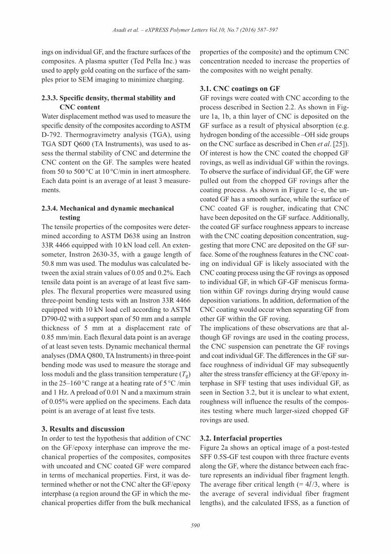
process as shown in Figure 5. The uncoated GF used
as the baseline for determining the CNC wt% on the
coated GF. The CNC content on the GF surface in-
creased from 0.44±0.07 to 3.58±0.02 wt% for 0.5
and 5 CNC wt% suspensions, respectively. It is noted
that the CNC wt% on the GF surface is not increas-
ing linearly with the CNC suspension concentration
used in coating process, e.g. the CNC content on the
GF coated with 1 CNC wt% solution is not twice of
that of the GF coated with 0.5 CNC wt%.
The thermal stability of the CNC-coated GF is also
plotted in Figure 5. The onset temperature of thermal
degradation of the neat CNC was 234.23±0.67 °C.
All the coated-GF degraded above this temperature
(lower bound). The onset temperature of thermal
degradation decreased with the increase in the CNC
content on the GF which was expected as it should
reach the lower bound with the increase in the CNC
content.
3.4. Fracture surface morphology
The fracture surface of the composites failed in the
tensile testing was studied using a FE-SEM. As shown
in Figure 6a, 6b, the main failure mechanism for un-
coated GF epoxy composites was interfacial debond-
ing as indicated by the clean pulled-out fibers devoid
of the matrix, suggesting weak fiber-matrix adhe-
sion. In contrast, the failure mechanisms for CNC-
coated GF epoxy composites were concurrent matrix
cracking, fiber breakage and interfacial debonding,
shown in Figure 6c, 6d, implying an improvement
in the interfacial bonding as a result of CNC coating.
Also, matrix residues on the pulled-out fibers (Fig-
ure 6d) and a rough fracture surface for both 1S-
30GF/epoxy and 2S-30GF/epoxy composites com-
pared to the smooth fracture surface for the uncoated
GF/epoxy composites suggest a better adhesion be-
tween fiber and matrix.
Asadi et al. – eXPRESS Polymer Letters Vol.10, No.7 (2016) 587–597
593
Figure 4. Optical polarized light micrographs of SFF speci-
mens after tensile test showing fracture events at
the GF: (a) GF/epoxy (polarized light of 75°),
(b) 0.5S-GF (polarized light 120°), (c) 0.5S-GF
(polarized light 80°), (d) 1S-GF (polarized light
90) and (e) 2S-GF (polarized light 75°)
Figure 5. CNC suspension concentration on the GF and com-
posites and onset temperature of thermal degrada-
tion for CNC-coated GF as a function of CNC con-
centration in the aqueous solution. Error bars are
1 standard deviation

3.5. Tensile and flexural properties
The effect of the CNC content on the tensile and
flexural properties of CNC coated GF/epoxy com-
posites are plotted in Figure 7. The incorporation of
CNC as a coating to GF enhances the elastic modulus
by ~10% for 1S-30GF/epoxy and 1.5S-30GF/epoxy
composites with respect to that of uncoated
GF/epoxy. This may be a result of the increase in the
stiffness of the GF/epoxy interphase due to presence
of CNC as according to Hashin [32], for an imper-
fect interface (i.e. displacement discontinuity across
the interface) an interfacial stiffness parameter can
be defined where a higher value of this parameter
suggests a faster rate of stress transfer across the
fiber/matrix interface and thus a higher modulus for
the composite [33]. Although this hypothesis could
not be validated in this study, Gao and Mäder [34]
showed how increases in the apparent modulus at the
GF/epoxy interphase resulted in increase in the com-
posite macroscopic modulus, which can be qualita-
tively linked to the current study where enhancement
in the apparent modulus of the GF/epoxy interphase
resulted in higher macroscopic modulus of the com-
posites. In addition, the tensile strength increased for
1S-30GF/epoxy (~10%) and 1.5S-30GF/ epoxy com-
posites with respect to that of 30GF/ epoxy compos-
ites. This increase reflects the higher IFSS (see Fig-
ure 2) inferring stronger interfacial interactions and
better stress transfer across the fiber/CNC/epoxy in-
terphase as also reported elsewhere [35]. The tensile
strength of the 2S-30GF/epoxy composite was ~12%
lower despite having higher IFSS compared to that
of 30GF/epoxy. This may be due to various mecha-
nisms including void formation within and around
the GF rovings as a result of incomplete infiltration
of the epoxy within the coated GF rovings and
breaking of the CNC coating as it becomes more
brittle with increase of its thickness. The strain at
break had a trend similar to that of the strength,
where the strain at break in 1S-30GF/epoxy and
Asadi et al. – eXPRESS Polymer Letters Vol.10, No.7 (2016) 587–597
594
Figure 6. SEM images for fracture surface of different epoxy composites; (a) and (b) uncoated 30GF/epoxy, (c) 1S-30GF/
epoxy, (d) 2S-30GF/epoxy

1.5S-30GF/epoxy composites increased by ~14 and
~10% while that of 2S-30GF/epoxy decreased com-
pared to uncoated 30GF/epoxy composites.
For composites made with 1S-GF and 1.5S-GF, the
flexural modulus and strength increased by ~40 and
~42%, respectively, with respect to those of uncoat-
ed 30GF/epoxy composites indicating better adhe-
sion between the glass fiber and epoxy due to higher
IFSS, and stress transfer at a faster rate as discussed
above. The strain at break follows similar trend to
that of axial strain, where it increased by ~10% for
1S-30GF/epoxy.
It is noted that the enhancement in flexural proper-
ties was larger than the enhancement in tensile prop-
erties at the same CNC content. The differences in
elastic moduli and strengths may result from the dif-
ference in tensile and flexural moduli of the epoxy
resin. In most epoxy systems, the tensile modulus is
higher than the flexural modulus while the tensile
strength is lower than the flexural strength (e.g. report
by Kinsella et al. [36]). In addition, for the strength
and the strain at break, a different mechanism may
be at play since these properties are typically domi-
nated by defects within the composite. For materials
with defect mediated failure, strength and strain at
break properties will be dependent on the number of
defects, their size, where they are located with re-
spect to the high stressed portions of the sample and
volume subjected to the highest tensile stress. For the
samples used in tensile and flexural testing, it is like-
ly that the defect numbers and size distributions are
similar in all samples tested; however, in the tensile
coupons, all the material in the gauge portion expe-
riences the maximum stress as compared to the to
the flexural sample configuration in which only the
outer surfaces of specimen are subjected to the max-
imum stress. With this in mind, for the tensile test-
ing, there is higher probability that a larger number
of defects is located in the high tensile stressed por-
tions of the sample and because of this, a lower ap-
plied load would be needed to induce fracture. More-
over, the larger enhancement of the flexural properties
compared to the enhancement of the tensile properties
can be due to the fact that the glass fibers are ran-
domly oriented in plane so that in tensile loading only
a portion of their length along the direction of the
applied load will bear loading. In case of the three-
point bending, the load direction is out of plane and
all the fibers (across the whole length) are available
to take up load and therefore enhancement in the
flexural properties would be higher.
3.6. Dynamic thermo-mechanical properties
The dynamic thermo-mechanical properties of the
composites below and above Tg are presented in
Table 1. At 25°C, the incorporation of CNC as a coat-
ing to GF rovings was shown to enhance the storage
modulus (E') for the 1S-30GF/epoxy and 1.5S-30GF/
epoxy composites, but lower the storage modulus for
2S-30GF/epoxy composites, as compared to that of
30GF/epoxy composites. The increase in the storage
modulus at 25°C can be attributed to the stiffening
of the GF/CNC/matrix interphase due to presence of
CNC particles, as discussed in Section 3.5. Although
the average value of the rubbery moduli (Er: the stor-
age modulus above Tg) measured at 90 °C for the
composites containing CNC-coated GF were lower
than that of the composite incorporating uncoated
GF, due to the large standard deviation in measured
properties, it was concluded that coating of the GF
with CNC did not impact the rubbery modulus. Stud-
ies have shown that addition of CNC in the epoxy
increased the rubbery modulus due to the formation
of a network of mechanically percolated CNC [16,
18, 21]. However, it is expected that CNC on the sur-
face of the GF do not form a percolated network
Asadi et al. – eXPRESS Polymer Letters Vol.10, No.7 (2016) 587–597
595
Figure 7. Effect of the CNC content (wt% in composite) in
CNC-coated 30GF/epoxy composites on tensile
and flexural properties. Error bars are 1 standard
deviation

within the polymer matrix. Hence, CNC cannot
strongly impact the polymer chain segmental motion
and consequently, the rubbery modulus. Presence of
CNC has no effect on the tanδ and the glass transi-
tion temperature (Tg).
4. Conclusions
This study demonstrated that introducing a small
amount of CNC in the form of a coating on GF can
enhance the IFSS and mechanical properties of short
GF/epoxy composites without increasing the weight.
The proposed mechanism for altering the composite
properties is the improvement of the interfacial ad-
hesion and stress transfer ability and rate across the
GF/epoxy interphase due to the CNC coating. Single
fiber fragmentation tests showed that coating of GF
up to 1.96 wt% (coated in 3 wt% aqueous CNC sus-
pension) was able to increase IFSS; however, the high-
est increase in IFSS (by 69%) was achieved for CNC
coating of 0.55 wt% (coated in CNC 1 wt% aqueous
CNC suspension). The CNC-GF/epoxy composites
produced using CNC coated chopped GF roving
showed increases in tensile and flexural properties,
which were attributed to the increase in IFSS asso-
ciated with the application of the GF coatings. The
greatest improvement in properties occurred when
CNC coating on GF rovings equal to 0.17 wt% of
composite was used. Specifically, the tensile elastic
modulus and strength by ~10%, tensile strain at
break by ~14%, the flexural modulus and strength
by ~40% and flexural strain at break by ~10%. It is
noted that the CNC coating did not significantly alter
the rubbery modulus, Tg and tanδ. The results high-
light that the use of CNC coatings on GF, is a possi-
ble approach for enhancing the mechanical proper-
ties of GF/epoxy composites with no weight penalty.
AcknowledgementsThis work was supported by funding from P3 Nano and the
U.S. Endowment for Forestry and Communities. The authors
would like to thank Prof. Jon Colton for providing mechan-
ical testing equipment.
References[1] U. S. Department of Energy: The quadrennial technol-
ogy review. p.39 (2011).
[2] Dorigato A., Morandi S., Pegoretti A.: Effect of nano -
clay addition on the fiber/matrix adhesion in epoxy/
glass composites. Journal of Composite Materials, 46,
1439–1451 (2012).
DOI: 10.1177/0021998311420311
[3] Pedrazzoli D., Pegoretti A., Kalaitzidou K.: Synergistic
effect of exfoliated graphite nanoplatelets and short
glass fiber on the mechanical and interfacial properties
of epoxy composites. Composites Science and Tech-
nology, 98, 15–21 (2014).
DOI: 10.1016/j.compscitech.2014.04.019
[4] Pedrazzoli D., Pegoretti A.: Silica nanoparticles as cou-
pling agents for polypropylene/glass composites. Com-
posites Science and Technology, 76, 77–83 (2013).
DOI: 10.1016/j.compscitech.2012.12.016
[5] Gao S-L., Mäder E., Plonka R.: Nanocomposite coat-
ings for healing surface defects of glass fibers and im-
proving interfacial adhesion. Composites Science and
Technology, 68, 2892–2901 (2008).
DOI: 10.1016/j.compscitech.2007.10.009
[6] Luo J-J., Daniel I. M.: Characterization and modeling
of mechanical behavior of polymer/clay nanocompos-
ites. Composites Science and Technology, 63, 1607–
1616 (2003).
DOI: 10.1016/S0266-3538(03)00060-5
[7] Hubbe M. A., Rojas O. J., Lucia L. A., Sain M.: Cellu-
losic nanocomposites: A review. BioResources, 3, 929–
980 (2008).
[8] Habibi Y., Lucia L. A., Rojas O. J.: Cellulose nanocrys-
tals: Chemistry, self-assembly, and applications. Chem-
ical Reviews, 110, 3479–3500 (2010).
DOI: 10.1021/cr900339w
[9] Moon R. J., Martini A., Nairn J., Simonsen J., Young-
blood J.: Cellulose nanomaterials review: Structure,
properties and nanocomposites. Chemical Society Re-
views, 40, 3941–3994 (2011).
DOI: 10.1039/C0CS00108B
[10] Roman M.: Toxicity of cellulose nanocrystals: A re-
view. Industrial Biotechnology, 11, 25–33 (2015).
DOI: 10.1089/ind.2014.0024
[11] Hansen, F., Brun, V., Keller, E., Wegner, T., Meador,
M., Friedersdorf, L.: Cellulose nanomaterials-A Path
towards commercialization. USDA Forest Service
Workshop report, Washington (2014).
[12] Beck-Candanedo S., Roman M., Gray D. G.: Effect of
reaction conditions on the properties and behavior of
wood cellulose nanocrystal suspensions. Biomacromol-
ecules, 6, 1048–1054 (2005).
DOI: 10.1021/bm049300p
Asadi et al. – eXPRESS Polymer Letters Vol.10, No.7 (2016) 587–597
596
Table 1. Viscoelastic properties of CNC-GF/epoxy compos-
ites in three-point bending mode
E': storage modulus
Er: rubbery modulus
Tg: glass transition temperature measured in tanδ peak
tanδ: value of tan δ peak
Note: Error bars are 1 standard deviation.
CompositeE' at 25°C
[MPa]
Er at 90°C
[MPa]
Tg[°C]
tanδ at Tg
30GF/epoxy 4932±586 250±21 50.3±0.7 0.61±0.06
1S-30GF/epoxy 5213±543 224±31 49.4±0.5 0.61±0.02
1.5S-30GF/epoxy 5614±695 228±22 50.2±0.8 0.65±0.07
2S-30GF/epoxy 4634±257 243±38 49.5±1.1 0.59±0.02

[13] Lee K-Y., Aitomäki Y., Berglund L. A., Oksman K.,
Bismarck A.: On the use of nanocellulose as reinforce-
ment in polymer matrix composites. Composites Sci-
ence and Technology, 105, 15–27 (2014).
DOI: 10.1016/j.compscitech.2014.08.032
[14] Xu S., Girouard N., Schueneman G., Shofner M. L.,
Meredith J. C.: Mechanical and thermal properties of
waterborne epoxy composites containing cellulose nano -
crystals. Polymer, 54, 6589-6598 (2013).
DOI: 10.1016/j.polymer.2013.10.011
[15] Ruiz M. M., Cavaillé J. Y., Dufresne A., Graillat C.,
Gérard J-F.: New waterborne epoxy coatings based on
cellulose nanofillers. Macromolecular Symposia, 169,
211–222 (2001).
DOI: 10.1002/1521-3900(200105)169:1<211::AID-
MASY211>3.0.CO;2-H
[16] Tang L., Weder C.: Cellulose whisker/epoxy resin nano -
composites. ACS Applied Materials and Interfaces, 2,
1073–1080 (2010).
DOI: 10.1021/am900830h
[17] Lu J., Askeland P., Drzal L. T.: Surface modification of
microfibrillated cellulose for epoxy composite applica-
tions. Polymer, 49, 1285–1296 (2008).
DOI: 10.1016/j.polymer.2008.01.028
[18] Girouard N., Schueneman G. T., Shofner M. L., Mered-
ith J. C.: Exploiting colloidal interfaces to increase dis-
persion, performance, and pot-life in cellulose nanocrys-
tal/waterborne epoxy composites. Polymer, 68, 111–121
(2015).
DOI: 10.1016/j.polymer.2015.05.009
[19] Gabr M. H., Elrahman M. A., Okubo K., Fujii T.: A
study on mechanical properties of bacterial cellulose/
epoxy reinforced by plain woven carbon fiber modified
with liquid rubber. Composites Part A: Applied Science
and Manufacturing, 41, 1263–1271 (2010).
DOI: 10.1016/j.compositesa.2010.05.010
[20] Peng S. X., Moon R. J., Youngblood J. P.: Design and
characterization of cellulose nanocrystal-enhanced epoxy
hardeners. Green Materials, 2, 193–205 (2014).
DOI: 10.1680/gmat.14.00015
[21] Ansari F., Galland S., Johansson M., Plummer C. J. G.,
Berglund L. A.: Cellulose nanofiber network for mois-
ture stable, strong and ductile biocomposites and in-
creased epoxy curing rate. Composites Part A: Applied
Science and Manufacturing, 63, 35–44 (2014).
DOI: 10.1016/j.compositesa.2014.03.017
[22] Barari B., Ellingham T. K., Ghamhia I. I., Pillai K. M.,
El-Hajjar R., Turng L-S., Sabo R.: Mechanical charac-
terization of scalable cellulose nano-fiber based com-
posites made using liquid composite molding process.
Composites Part B: Engineering, 84, 277–284 (2016).
DOI: 10.1016/j.compositesb.2015.08.040
[23] Miao C., Hamad W. Y.: Cellulose reinforced polymer
composites and nanocomposites: A critical review. Cel-
lulose, 20, 2221–2262 (2013).
DOI: 10.1007/s10570-013-0007-3
[24] Karger-Kocsis J., Mahmood H., Pegoretti A.: Recent
advances in fiber/matrix interphase engineering for poly-
mer composites. Progress in Materials Science, 73, 1–43
(2015).
DOI: 10.1016/j.pmatsci.2015.02.003
[25] Chen Y., Zhou X., Yin X., Lin Q., Zhu M.: A novel
route to modify the interface of glass fiber-reinforced
epoxy resin composite via bacterial cellulose. Interna-
tional Journal of Polymeric Materials and Polymeric
Biomaterials, 63, 221–227 (2013).
DOI: 10.1080/00914037.2013.830250
[26] Postek M. T., Moon R. J., Rudie A. W., Bilodeau M. A.:
Production and applications of cellulose. Tappi Press.
Peachtree Corners (2013).
[27] Rich M. J., Drzal L. T., Hunston D., Holmes G., Mc-
Donough W.: Round robin assessment of the single
fiber fragmentation test. in ‘Procedings of the American
Society for Composites 17th Technical Conference, West
Lafayette, USA’ p.10 (2002)..
[28] Kelly A., Tyson W.: Tensile properties of fibre-rein-
forced metals: Copper/tungsten and copper/molybde-
num. Journal of the Mechanics and Physics of Solids,
13, 329–350 (1965).
DOI: 10.1016/0022-5096(65)90035-9
[29] Klein C. A.: Characteristic strength, Weibull modulus,
and failure probability of fused silica glass. Optical En-
gineering, 48, 113401/1–113401/11 (2009).
DOI: 10.1117/1.3265716
[30] Mullin J. V., Mazzio V. F.: The effects of matrix and in-
terface modification on local fractures of carbon fibers
in epoxy. Journal of the Mechanics and Physics of Solids,
20, 391–394 (1972).
DOI: 10.1016/0022-5096(72)90016-6
[31] Zhou X-F., Nairn J. A., Wagner H. D.: Fiber–matrix ad-
hesion from the single-fiber composite test: Nucleation
of interfacial debonding. Composites Part A: Applied
Science and Manufacturing, 30, 1387–1400 (1999).
DOI: 10.1016/S1359-835X(99)00043-3
[32] Hashin Z.: Thermoelastic properties of fiber composites
with imperfect interface. Mechanics of Materials, 8,
333–348 (1990).
DOI: 10.1016/0167-6636(90)90051-G
[33] Nairn J. A.: Generalized shear-lag analysis including
imperfect interfaces. Advanced Composites Letters, 13,
263–274 (2004).
[34] Gao S-L., Mäder E.: Characterisation of interphase nano -
scale property variations in glass fibre reinforced
polypropylene and epoxy resin composites. Composites
Part A: Applied Science and Manufacturing, 33, 559–
576 (2002).
DOI: 10.1016/S1359-835X(01)00134-8
[35] Madhukar M. S., Drzal L. T.: Fiber-matrix adhesion
and its effect on composite mechanical properties: II.
Longitudinal (0°) and transverse (90°) tensile and flex-
ure behavior of graphite/epoxy composites. Journal of
Composite Materials, 25, 958–991 (1991).
DOI: 10.1177/002199839102500802
[36] Kinsella M., Murray D., Crane D., Mancinelli J., Kranjc
M.: Mechanical properties of polymeric composites re-
inforced with high strength glass fibers. in ‘33rd Inter-
national SAMPE Technical Conference, Seatle, USA’
Vol. 33, 1644–1657 (2001).
Asadi et al. – eXPRESS Polymer Letters Vol.10, No.7 (2016) 587–597
597


![Mechanical interfacial adhesion of carbon fibers ... · is the controlling factor in obtaining optimum mechanical properties of composites [11-13]. To achieve good interfacial adhesion](https://img.pdfslide.us/doc/110x75/5fb4f2941761df3d6e2a6807/mechanical-interfacial-adhesion-of-carbon-fibers-is-the-controlling-factor-in.jpg)


![1 Interfacial Rheology System. 2 Background of Interfacial Rheology Interfacial Shear Stress Interfacial Shear Viscosity = [ ]](https://img.pdfslide.us/doc/110x75/56649d1f5503460f949f3d29/1-interfacial-rheology-system-2-background-of-interfacial-rheology-interfacial.jpg)