Embed Size (px)
Citation preview
IOSR Journal of Mechanical and Civil Engineering (IOSR-JMCE)
e-ISSN: 2278-1684,p-ISSN: 2320-334X,
PP 67-79
www.iosrjournals.org
International Conference on Emerging Trends in Engineering & Management 67 |Page
(ICETEM-2016)
Improving The Crashworthiness Of An Automobile Bumper
Arun Basil Jacob1, Arunkumar O.N
2
1.PG Student, Dept of Mechanical Engg., SNGCE, Kolenchery, Kerala.([email protected])
2 AssociateProfessor, Dept of Mechanical Engg., SNGCE, Kolenchery, Kerala. ([email protected] )
Abstract: This paper proposes a new bumper modelwhich has more crashworthiness than the existing
bumper.Rate of automobile accidents are increasing each year and the main reason for it being the lack of
proper safety systems in the vehicle. In case of automobiles, frontal impact constitutes 60% of the total crash
cases. The project aims at improving the crashworthiness of an automobile bumper. The automobile selected for
the purpose is Toyota Camry model released in 2012. The bumper of the existing model had steel bumper. The
energy absorbed by the existing model was found out utilizing PTC Creo, Hypermesh and LS-Dyna softwares.
LS-Dyna is used to predict accurately the material behavior during impact. Two new designs were proposed.
Model containing honeycomb inside the existing bumper being the first one and foam incorporated design as the
second. The analysis of the new systems and also of the existing steel bumper was done. The material models
used for the study included MAT_ PIECEWISE_ LINEAR_ PLASTICITY (MAT24), MAT _ RIGID (MAT20) and
MAT _ CRUSHABLE _ FOAM (MAT63). The newly designed models namely the foam and honeycomb
incorporated bumpers show better impact absorption capacity. In the honeycomb model the increased energy
absorption capacity is 11.26 % compared to the existing steel bumper and in the foam bumper the increased
energy absorption capacity is 6%.
Keywords: Crashworthiness,foam, honeycomb,impact energy
I. Introduction In a frontal or rear crash, the bumper beam is the primary component which undergoes damage and
transfers the forces to the rest of the structure. Thus, the modern bumper beam systems should play a key part in
the safety concept of an automobile, ensuring that minimal accelerations are transferred to the passenger.
Further the automotive producers are demanding for robust bumper beam systems showing good and
reproducible impact behavior.To evaluate the crashworthiness of new cars, different programs exist for example
the NCAP (New Car Assessment Program). NCAP contains several standardized tests for new vehicles, where
the damage to the occupants is evaluated through crash-test dummies and structural performance. Results from
the NCAP tests are helping the motoring consumers to choose a crashworthy car. It is worth to note, however,
conducting full-scale crash test of a car is always time consuming and expensive.
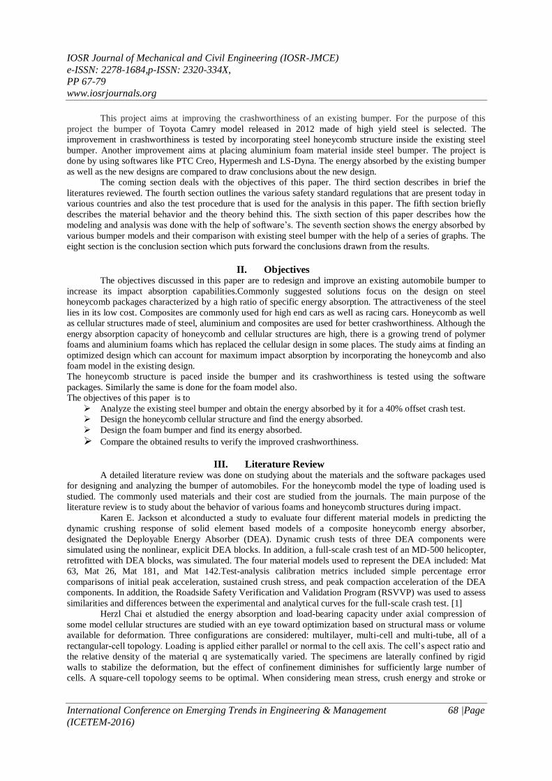
Figure 1 shows that the largest proportion of accidents, about 60%, occurs at the front of the vehicle and of these
offset impacts are the most commonly seen accidental situations on roads, and they also give rise to the highest
portion of deaths . Oblique or side collisions are less frequent and serious in their effects, and rear impacts and
roll-overs are relatively rare.
Fig1:-Distribution ofpassenger car accidents by type of collision. (Frank &Gruber,1992)
IOSR Journal of Mechanical and Civil Engineering (IOSR-JMCE)
e-ISSN: 2278-1684,p-ISSN: 2320-334X,
PP 67-79
www.iosrjournals.org
International Conference on Emerging Trends in Engineering & Management 68 |Page
(ICETEM-2016)
This project aims at improving the crashworthiness of an existing bumper. For the purpose of this
project the bumper of Toyota Camry model released in 2012 made of high yield steel is selected. The
improvement in crashworthiness is tested by incorporating steel honeycomb structure inside the existing steel
bumper. Another improvement aims at placing aluminium foam material inside steel bumper. The project is
done by using softwares like PTC Creo, Hypermesh and LS-Dyna. The energy absorbed by the existing bumper
as well as the new designs are compared to draw conclusions about the new design.
The coming section deals with the objectives of this paper. The third section describes in brief the
literatures reviewed. The fourth section outlines the various safety standard regulations that are present today in
various countries and also the test procedure that is used for the analysis in this paper. The fifth section briefly
describes the material behavior and the theory behind this. The sixth section of this paper describes how the
modeling and analysis was done with the help of software’s. The seventh section shows the energy absorbed by
various bumper models and their comparison with existing steel bumper with the help of a series of graphs. The
eight section is the conclusion section which puts forward the conclusions drawn from the results.
II. Objectives The objectives discussed in this paper are to redesign and improve an existing automobile bumper to
increase its impact absorption capabilities.Commonly suggested solutions focus on the design on steel
honeycomb packages characterized by a high ratio of specific energy absorption. The attractiveness of the steel
lies in its low cost. Composites are commonly used for high end cars as well as racing cars. Honeycomb as well
as cellular structures made of steel, aluminium and composites are used for better crashworthiness. Although the
energy absorption capacity of honeycomb and cellular structures are high, there is a growing trend of polymer
foams and aluminium foams which has replaced the cellular design in some places. The study aims at finding an
optimized design which can account for maximum impact absorption by incorporating the honeycomb and also
foam model in the existing design.
The honeycomb structure is paced inside the bumper and its crashworthiness is tested using the software
packages. Similarly the same is done for the foam model also.
The objectives of this paper is to
Analyze the existing steel bumper and obtain the energy absorbed by it for a 40% offset crash test.
Design the honeycomb cellular structure and find the energy absorbed.
Design the foam bumper and find its energy absorbed.
Compare the obtained results to verify the improved crashworthiness.
III. Literature Review A detailed literature review was done on studying about the materials and the software packages used
for designing and analyzing the bumper of automobiles. For the honeycomb model the type of loading used is
studied. The commonly used materials and their cost are studied from the journals. The main purpose of the
literature review is to study about the behavior of various foams and honeycomb structures during impact.
Karen E. Jackson et alconducted a study to evaluate four different material models in predicting the
dynamic crushing response of solid element based models of a composite honeycomb energy absorber,
designated the Deployable Energy Absorber (DEA). Dynamic crush tests of three DEA components were
simulated using the nonlinear, explicit DEA blocks. In addition, a full-scale crash test of an MD-500 helicopter,
retrofitted with DEA blocks, was simulated. The four material models used to represent the DEA included: Mat
63, Mat 26, Mat 181, and Mat 142.Test-analysis calibration metrics included simple percentage error
comparisons of initial peak acceleration, sustained crush stress, and peak compaction acceleration of the DEA
components. In addition, the Roadside Safety Verification and Validation Program (RSVVP) was used to assess
similarities and differences between the experimental and analytical curves for the full-scale crash test. [1]
Herzl Chai et alstudied the energy absorption and load-bearing capacity under axial compression of
some model cellular structures are studied with an eye toward optimization based on structural mass or volume
available for deformation. Three configurations are considered: multilayer, multi-cell and multi-tube, all of a
rectangular-cell topology. Loading is applied either parallel or normal to the cell axis. The cell’s aspect ratio and
the relative density of the material q are systematically varied. The specimens are laterally confined by rigid
walls to stabilize the deformation, but the effect of confinement diminishes for sufficiently large number of
cells. A square-cell topology seems to be optimal. When considering mean stress, crush energy and stroke or
IOSR Journal of Mechanical and Civil Engineering (IOSR-JMCE)
e-ISSN: 2278-1684,p-ISSN: 2320-334X,
PP 67-79
www.iosrjournals.org
International Conference on Emerging Trends in Engineering & Management 69 |Page
(ICETEM-2016)
densification strain on the basis of minimum mass and volume simultaneously, relative density 𝜌 = 0.5 seem to
be a viable compromise among conflicting trends. [2]
Qingchun Wang et alhas done a theoretical analysis to predict the dynamic axial crushing behavior of
aluminium foam-filled top hat and double hat sections made from mild steel material. The deformation mode
from the test results was used to create a deformation model for the theoretical analysis. According to the energy
method and the super folding element theory, the mean dynamic crushing loads of the aluminium foam-filled
hat sections and the interactive effect between the aluminium foam and hat sections were theoretically predicted.
The mean dynamic crushing loads and the interactive effect predicted by this theoretical analysis were in good
agreement with the experimental results. The theoretical prediction results showed that the interactive effect was
mainly from the aluminium foam. [3]
F. Ince et alput forward a new finding that the safety factor of a vehicle mostly depends on the behavior
of frontal automotive structures during crash. These structures, which are usually prismatic thin walled
structures and are defined as crash boxes, are the main energy absorbers of the crash. Crashworthiness of these
structures depends on their dimensions and materials. In this study, the impact behavior of the crash boxes made
of steel and aluminum materials are investigated experimentally and numerically. The crash tests are performed
by using a drop test unit. The crash test is also modeled using the ANSYS finite element software. The crash
box is discretized by using shell elements. The deformations as a result of crash tests are compared with the
finite element results. The impact force during the crash is also compared with the forces obtained using the
finite element method. The results are found to be in an agreement. The impact behavior of a hybrid box made
of steel and aluminum is also investigated numerically. The analyses are performed changing the parameters
such as aluminum thickness, aluminum to steel weight ratio. The hybrid crash box is optimized based on the
deformations to obtain the minimum weight. [4]
Bryan Chuet al developed an economical frontal crash structure which may be used in the Formula
Ford series. The structure must meet three test conditions: a static crush test, a push off test, and a dynamic sled
impact. There are no limitations on the materials used in the construction of the crash structure but the
manufacturing costs must be kept under £400. The size limitations are as determined by the regulations in the
Formula Ford series. [5]
IV. Safety Standards And Procedure The commonly accepted regulations for vehicle safety are EURO NCAP (European New Car
Assessment Program) 94 and FMVSS (Federal Motor Vehicle Safety Standards) 208. Improvements to vehicle
safety result from legislation (much of which is now agreed in the European Union) consumer information,
product liability considerations as well as specific initiatives of the car manufacturing industry. EU legislation
aims for a minimum but high level of protection across the product line, consumer information aims to
encourage the highest possible levels of safety performance based on state of the art testing and protocols, and
car industry policies increasingly promote safety as a marketable commodity.
Further EU action on vehicle safety is essential if new goals and targets are to be met. Priority policy
actions for reducing serious and fatal casualties identified by research are a standardized test method for car to
car compatibility, truck to car compatibility and improved methods for front, side and rear impact protection for
car occupants, improved frontal protection for vulnerable road users over and above what is covered in current
legislation, implementation of Intelligent Speed Adaptation systems, seat belt reminders in all seating positions,
event and journey data recorders and identification of further systems with large potential for casualty savings.
As noted by Euro NCAP, the presence of international players in European Markets inevitably will lead
to a new push for global road safety regulations. Care must be taken to ensure that existing safety levels in
Europe are not compromised. Although, it has been observed, while it is often stated that vehicle design to
reduce the environmental footprint of motor vehicles is in conflict with improved road safety, these challenges
are likely to be overcome given the advances in new modern technologies. Countries active in safety typically
engage in international legislative development work, carry out national research and monitoring of vehicle
safety, support the influential European New Car Assessment Program (Euro NCAP), ensure that safety helmet
and safety restraint usage laws are properly enforced and encourage local car industry to fast track key safety
measures through government procurement and in-house travel policies. [6]
Federal Motor Vehicle Safety Standards (FMVSS) are U.S. federal regulations specifying design,
construction, performance, and durability requirements for motor vehicles and regulated automobile safety-
related components, systems, and design features. They are the U.S. counterpart to the UN Regulations
developed by the World Forum for Harmonization of Vehicle Regulations and recognized to varying degree by
IOSR Journal of Mechanical and Civil Engineering (IOSR-JMCE)
e-ISSN: 2278-1684,p-ISSN: 2320-334X,
PP 67-79
www.iosrjournals.org
International Conference on Emerging Trends in Engineering & Management 70 |Page
(ICETEM-2016)
most countries except the United States. Canada has a system of analogous rules called the Canada Motor
Vehicle Safety Standards (CMVSS), which overlap substantially but not completely in content and structure
with the FMVSS. The FMVSS/CMVSS requirements differ significantly from the international UN
requirements, so private import of vehicles not originally manufactured for the United States market is difficult
or impossible. [7]
Euro NCAP (European New Car Assessment Program) is a voluntary vehicle safety rating system
which originated in the UK but is now backed by the European Commission, seven European governments, as
well as motoring and consumer organizations in every EU country.
The program is modeled after the New Car Assessment Program (NCAP), introduced 1979 by the
U.S. National Highway Traffic Safety Administration. They publish safety reports on new cars, and awards 'star
ratings' based on the performance of the vehicles in a variety of crash tests, including front, side and pole
impacts, and impacts with pedestrians. The top overall rating is five stars.
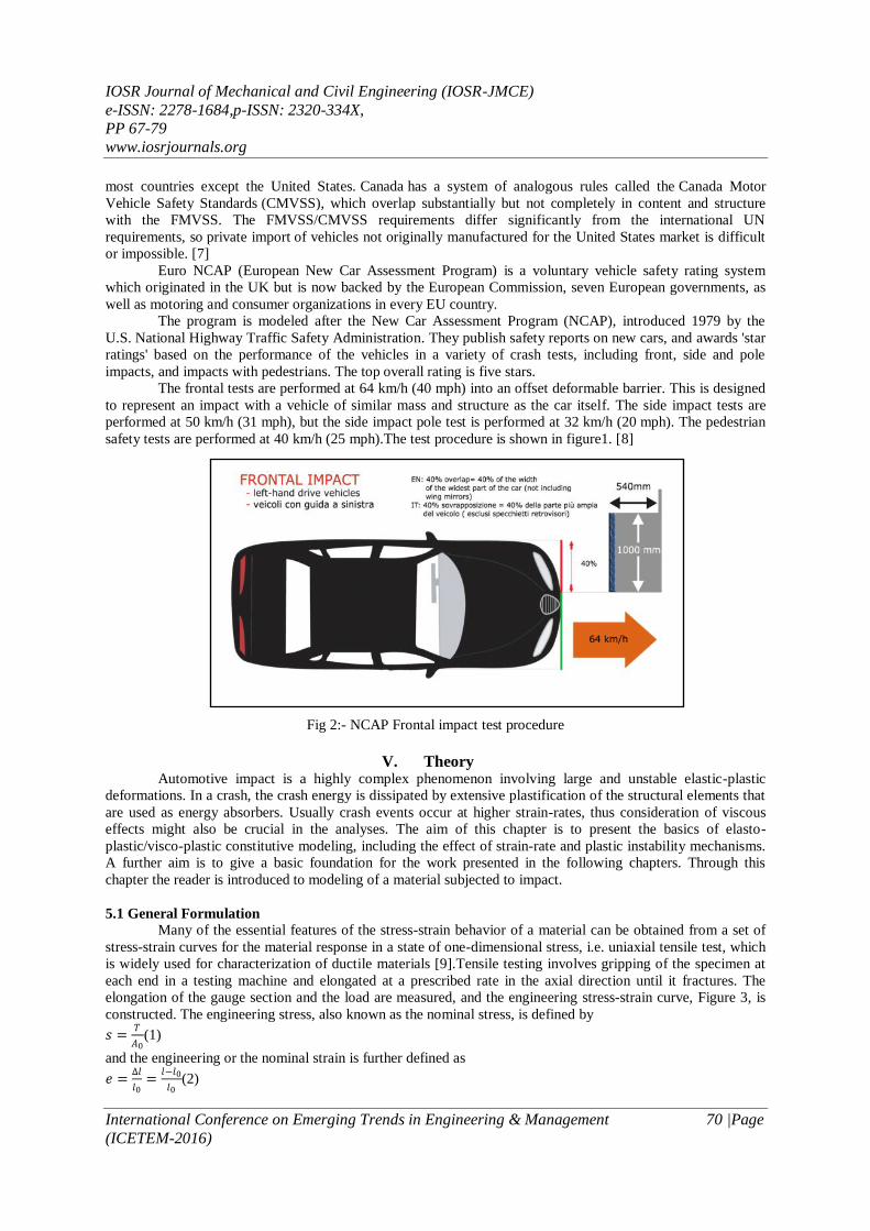
The frontal tests are performed at 64 km/h (40 mph) into an offset deformable barrier. This is designed
to represent an impact with a vehicle of similar mass and structure as the car itself. The side impact tests are
performed at 50 km/h (31 mph), but the side impact pole test is performed at 32 km/h (20 mph). The pedestrian
safety tests are performed at 40 km/h (25 mph).The test procedure is shown in figure1. [8]
Fig 2:- NCAP Frontal impact test procedure
V. Theory Automotive impact is a highly complex phenomenon involving large and unstable elastic-plastic
deformations. In a crash, the crash energy is dissipated by extensive plastification of the structural elements that
are used as energy absorbers. Usually crash events occur at higher strain-rates, thus consideration of viscous
effects might also be crucial in the analyses. The aim of this chapter is to present the basics of elasto-
plastic/visco-plastic constitutive modeling, including the effect of strain-rate and plastic instability mechanisms.
A further aim is to give a basic foundation for the work presented in the following chapters. Through this
chapter the reader is introduced to modeling of a material subjected to impact.
5.1 General Formulation
Many of the essential features of the stress-strain behavior of a material can be obtained from a set of
stress-strain curves for the material response in a state of one-dimensional stress, i.e. uniaxial tensile test, which
is widely used for characterization of ductile materials [9].Tensile testing involves gripping of the specimen at
each end in a testing machine and elongated at a prescribed rate in the axial direction until it fractures. The
elongation of the gauge section and the load are measured, and the engineering stress-strain curve, Figure 3, is
constructed. The engineering stress, also known as the nominal stress, is defined by
𝑠 =𝑇
𝐴0(1)
and the engineering or the nominal strain is further defined as
𝑒 =∆𝑙
𝑙0=
𝑙−𝑙0
𝑙0(2)
IOSR Journal of Mechanical and Civil Engineering (IOSR-JMCE)
e-ISSN: 2278-1684,p-ISSN: 2320-334X,
PP 67-79
www.iosrjournals.org
International Conference on Emerging Trends in Engineering & Management 71 |Page
(ICETEM-2016)
where T is the applied axial load, A0is the undeformed area of the cross-section and 𝑙0and lare the initial and the
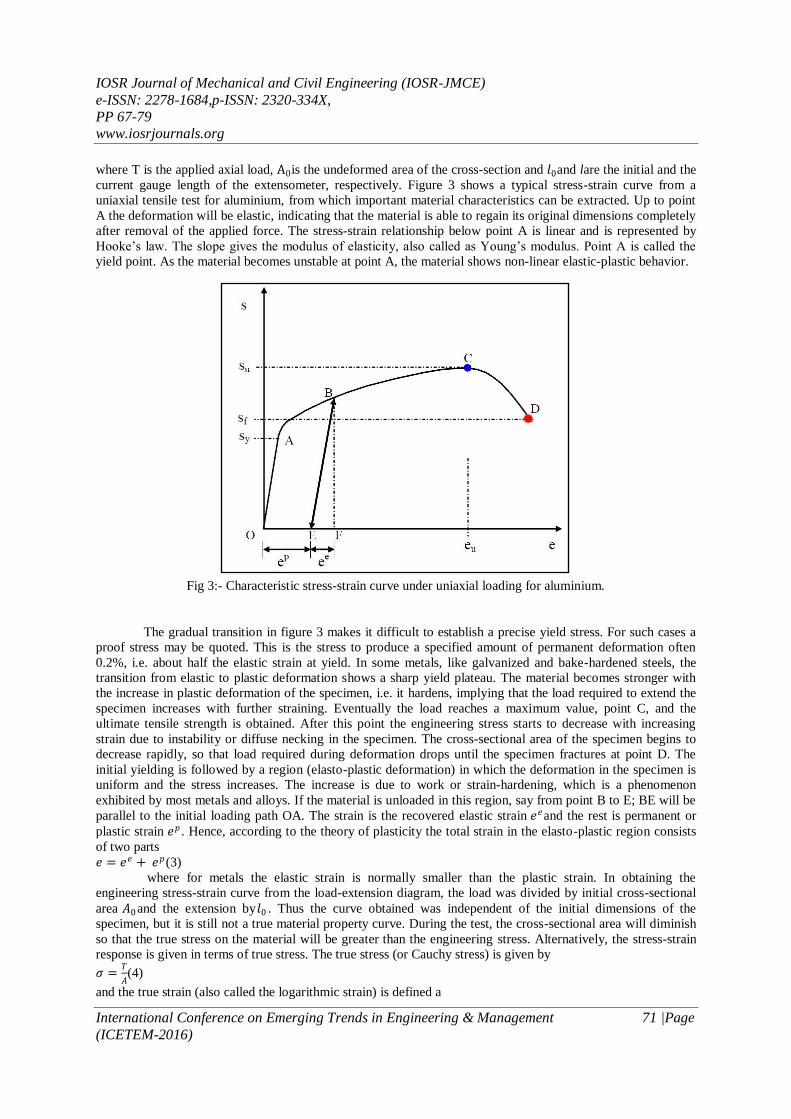
current gauge length of the extensometer, respectively. Figure 3 shows a typical stress-strain curve from a
uniaxial tensile test for aluminium, from which important material characteristics can be extracted. Up to point
A the deformation will be elastic, indicating that the material is able to regain its original dimensions completely
after removal of the applied force. The stress-strain relationship below point A is linear and is represented by
Hooke’s law. The slope gives the modulus of elasticity, also called as Young’s modulus. Point A is called the
yield point. As the material becomes unstable at point A, the material shows non-linear elastic-plastic behavior.
Fig 3:- Characteristic stress-strain curve under uniaxial loading for aluminium.
The gradual transition in figure 3 makes it difficult to establish a precise yield stress. For such cases a
proof stress may be quoted. This is the stress to produce a specified amount of permanent deformation often
0.2%, i.e. about half the elastic strain at yield. In some metals, like galvanized and bake-hardened steels, the
transition from elastic to plastic deformation shows a sharp yield plateau. The material becomes stronger with
the increase in plastic deformation of the specimen, i.e. it hardens, implying that the load required to extend the
specimen increases with further straining. Eventually the load reaches a maximum value, point C, and the
ultimate tensile strength is obtained. After this point the engineering stress starts to decrease with increasing
strain due to instability or diffuse necking in the specimen. The cross-sectional area of the specimen begins to
decrease rapidly, so that load required during deformation drops until the specimen fractures at point D. The
initial yielding is followed by a region (elasto-plastic deformation) in which the deformation in the specimen is
uniform and the stress increases. The increase is due to work or strain-hardening, which is a phenomenon
exhibited by most metals and alloys. If the material is unloaded in this region, say from point B to E; BE will be
parallel to the initial loading path OA. The strain is the recovered elastic strain 𝑒𝑒and the rest is permanent or
plastic strain 𝑒𝑝 . Hence, according to the theory of plasticity the total strain in the elasto-plastic region consists
of two parts
𝑒 = 𝑒𝑒 + 𝑒𝑝(3)
where for metals the elastic strain is normally smaller than the plastic strain. In obtaining the
engineering stress-strain curve from the load-extension diagram, the load was divided by initial cross-sectional
area 𝐴0 and the extension by𝑙0 . Thus the curve obtained was independent of the initial dimensions of the
specimen, but it is still not a true material property curve. During the test, the cross-sectional area will diminish
so that the true stress on the material will be greater than the engineering stress. Alternatively, the stress-strain
response is given in terms of true stress. The true stress (or Cauchy stress) is given by
𝜎 =𝑇
𝐴(4)
and the true strain (also called the logarithmic strain) is defined a
IOSR Journal of Mechanical and Civil Engineering (IOSR-JMCE)
e-ISSN: 2278-1684,p-ISSN: 2320-334X,
PP 67-79
www.iosrjournals.org
International Conference on Emerging Trends in Engineering & Management 72 |Page
(ICETEM-2016)
𝑑𝜀 = 𝑑𝑙
𝑙⇒ 𝜀 =
𝑑𝑙
𝑙
𝑙
𝑙0= 𝑙𝑛
𝑙
𝑙0(5)
where A is the current or deformed cross-sectional area and l is the current or deformed gauge length of
the specimen. The relation between the nominal and the true strain is obtained by combining Equations (2) and
(5) which gives
𝜀 = ln(1 + 𝑒)(6)
Assuming the constancy-of-volume condition for ductile metals, it is possible to write
𝐴0𝑙0 = 𝐴𝑙(7)
where the elastic strains, that are assumed to be small, are neglected. Hence the relationship between the
nominal and the true stress may be obtained as
𝜎 = 𝑇
𝐴=
𝑇𝑙
𝐴0 𝑙0= 𝑠(1 + 𝑒)(8)
As mentioned, the load, and therefore also the nominal stress, required for further deformation, falls off
after reaching diffuse necking. However, the metal continues to strain-harden all the way to fracture. This means
that the true stress required to produce further deformation should also increase. Equation (8) is derived from
assuming both constancy of volume and homogeneous distribution of strain along the gauge length of the
specimen. Beyond the maximum load the true stress should be determined from actual measurements of load
and cross-sectional area, while the true strain should be based on the actual area measurements.
5.2 Toughness
In materials science and metallurgy, toughness is the ability of a material to absorb energy and
plastically deform without fracturing. One definition of material toughness is the amount of energy per unit
volume that a material can absorb before rupturing. Toughness can also be defined as a material's resistance
to fracture when stressed. Toughness can also be defined with respect to regions of a stress-strain diagram.
Toughness is related to the area under the stress-strain curve. In order to be tough, a material must be both
strong and ductile. For example, brittle materials (like ceramics) that are strong but with limited ductility are not
tough, conversely, very ductile materials with low strengths are also not tough. To be tough, a material should
withstand both high stresses and high strains. Generally speaking, strength indicates how much force the
material can support, while toughness indicates how much energy a material can absorb before rupturing. The
ability of a metal to deform plastically and to absorb energy in the process before fracture is termed toughness.
The emphasis of this definition should be placed on the ability to absorb energy before fracture. Recall that
ductility is a measure of how much something deforms plastically before fracture, but just because a material is
ductile does not make it tough. The key to toughness is a good combination of strength and ductility. A material
with high strength and high ductility will have more toughness than a material with low strength and high
ductility. Therefore, one way to measure toughness is by calculating the area under the stress strain curve from a
tensile test. This value is simply called “material toughness” and it has units of energy per volume. Material
toughness equates to a slow absorption of energy by the material.
5.3 Honeycomb And Foam Models
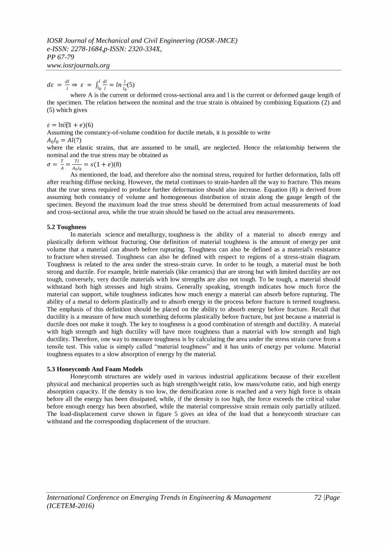
Honeycomb structures are widely used in various industrial applications because of their excellent
physical and mechanical properties such as high strength/weight ratio, low mass/volume ratio, and high energy
absorption capacity. If the density is too low, the densification zone is reached and a very high force is obtain
before all the energy has been dissipated, while, if the density is too high, the force exceeds the critical value
before enough energy has been absorbed, while the material compressive strain remain only partially utilized.
The load-displacement curve shown in figure 5 gives an idea of the load that a honeycomb structure can
withstand and the corresponding displacement of the structure.
IOSR Journal of Mechanical and Civil Engineering (IOSR-JMCE)
e-ISSN: 2278-1684,p-ISSN: 2320-334X,
PP 67-79
www.iosrjournals.org
International Conference on Emerging Trends in Engineering & Management 73 |Page
(ICETEM-2016)
Fig 4:- Load-displacement curve for a typical honeycomb structure
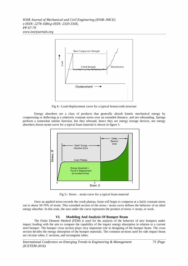
Energy absorbers are a class of products that generally absorb kinetic mechanical energy by
compressing or deflecting at a relatively constant stress over an extended distance, and not rebounding. Springs
perform a somewhat similar function, but they rebound, hence they are energy storage devices, not energy
absorbers.Stress-strain curve for a typical foam material is shown in figure 5.
Fig 5:- Stress – strain curve for a typical foam material
Once an applied stress exceeds the crush plateau, foam will begin to compress at a fairly constant stress
out to about 50-70% of strain. This extended section of the stress / strain curve defines the behavior of an ideal
energy absorber. In this zone, the area under the curve represents the product of stress × strain, or work.
VI. Modeling And Analysis Of Bumper Beam The Finite Element Method (FEM) is used for the analysis of the behavior of new bumpers under
impact loading with the aim to compare the capability of the impact energy absorption in relation to a current
steel bumper. The bumper cross section plays very important role in designing of the bumper beam. The cross
section decides the energy absorption of the bumper materials. The common sections used for side impact beam
are circular tubes, C sections, and rectangular tubes.
IOSR Journal of Mechanical and Civil Engineering (IOSR-JMCE)
e-ISSN: 2278-1684,p-ISSN: 2320-334X,
PP 67-79
www.iosrjournals.org
International Conference on Emerging Trends in Engineering & Management 74 |Page
(ICETEM-2016)
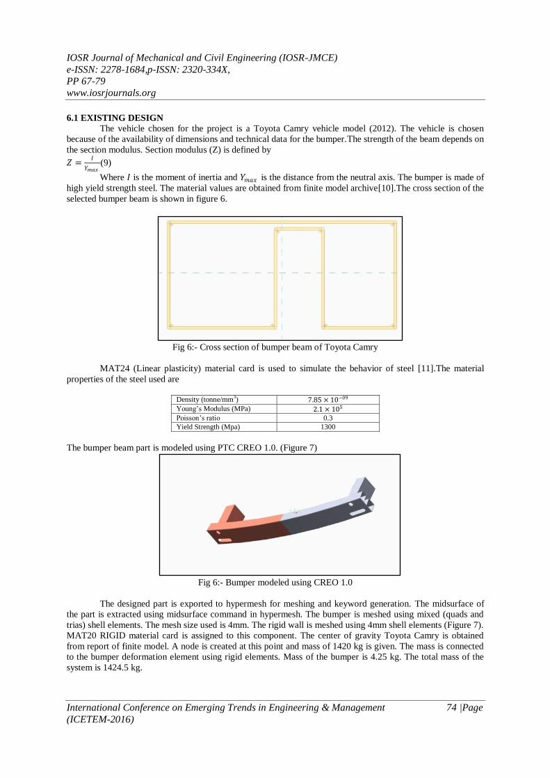
6.1 EXISTING DESIGN
The vehicle chosen for the project is a Toyota Camry vehicle model (2012). The vehicle is chosen
because of the availability of dimensions and technical data for the bumper.The strength of the beam depends on
the section modulus. Section modulus (Z) is defined by
𝑍 =𝐼
𝑌𝑚𝑎𝑥(9)
Where 𝐼 is the moment of inertia and 𝑌𝑚𝑎𝑥 is the distance from the neutral axis. The bumper is made of
high yield strength steel. The material values are obtained from finite model archive[10].The cross section of the
selected bumper beam is shown in figure 6.
Fig 6:- Cross section of bumper beam of Toyota Camry
MAT24 (Linear plasticity) material card is used to simulate the behavior of steel [11].The material
properties of the steel used are
Density (tonne/mm3) 7.85 × 10−09
Young’s Modulus (MPa) 2.1 × 10⁵
Poisson’s ratio 0.3
Yield Strength (Mpa) 1300
The bumper beam part is modeled using PTC CREO 1.0. (Figure 7)
Fig 6:- Bumper modeled using CREO 1.0
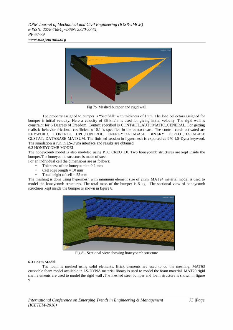
The designed part is exported to hypermesh for meshing and keyword generation. The midsurface of
the part is extracted using midsurface command in hypermesh. The bumper is meshed using mixed (quads and
trias) shell elements. The mesh size used is 4mm. The rigid wall is meshed using 4mm shell elements (Figure 7).
MAT20 RIGID material card is assigned to this component. The center of gravity Toyota Camry is obtained
from report of finite model. A node is created at this point and mass of 1420 kg is given. The mass is connected
to the bumper deformation element using rigid elements. Mass of the bumper is 4.25 kg. The total mass of the
system is 1424.5 kg.
IOSR Journal of Mechanical and Civil Engineering (IOSR-JMCE)
e-ISSN: 2278-1684,p-ISSN: 2320-334X,
PP 67-79
www.iosrjournals.org
International Conference on Emerging Trends in Engineering & Management 75 |Page
(ICETEM-2016)
Fig 7:- Meshed bumper and rigid wall
The property assigned to bumper is “SectShll” with thickness of 1mm. The load collectors assigned for
bumper is initial velocity. Here a velocity of 36 km/hr is used for giving initial velocity. The rigid wall is
constraint for 6 Degrees of Freedom. Contact specified is CONTACT_AUTOMATIC_GENERAL. For getting
realistic behavior frictional coefficient of 0.1 is specified in the contact card. The control cards activated are
KEYWORD, CONTROL CPU,CONTROL ENERGY,DATABASE BINARY D3PLOT,DATABASE
GLSTAT, DATABASE MATSUM. The finished session in hypermesh is exported as 970 LS-Dyna keyword.
The simulation is run in LS-Dyna interface and results are obtained.
6.2 HONEYCOMB MODEL
The honeycomb model is also modeled using PTC CREO 1.0. Two honeycomb structures are kept inside the
bumper.The honeycomb structure is made of steel.
For an individual cell the dimensions are as follows:
• Thickness of the honeycomb= 0.2 mm
• Cell edge length = 10 mm
• Total height of cell = 55 mm
The meshing is done using hypermesh with minimum element size of 2mm. MAT24 material model is used to
model the honeycomb structures. The total mass of the bumper is 5 kg. The sectional view of honeycomb
structures kept inside the bumper is shown in figure 8.
Fig 8:- Sectional view showing honeycomb structure
6.3 Foam Model
The foam is meshed using solid elements. Brick elements are used to do the meshing. MAT63
crushable foam model available in LS-DYNA material library is used to model the foam material. MAT20 rigid
shell elements are used to model the rigid wall .The meshed steel bumper and foam structure is shown in figure
9.
IOSR Journal of Mechanical and Civil Engineering (IOSR-JMCE)
e-ISSN: 2278-1684,p-ISSN: 2320-334X,
PP 67-79
www.iosrjournals.org
International Conference on Emerging Trends in Engineering & Management 76 |Page
(ICETEM-2016)
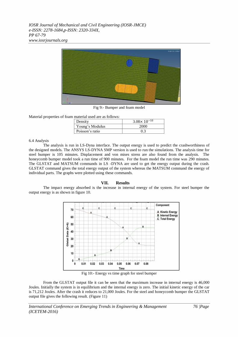
Fig 9:- Bumper and foam model
Material properties of foam material used are as follows:
Density 3.08× 10⁻¹⁰
Young’s Modulus 2000
Poisson’s ratio 0.3
6.4 Analysis
The analysis is run in LS-Dyna interface. The output energy is used to predict the crashworthiness of
the designed models. The ANSYS LS-DYNA SMP version is used to run the simulations. The analysis time for
steel bumper is 105 minutes. Displacement and von mises stress are also found from the analysis. The
honeycomb bumper model took a run time of 900 minutes. For the foam model the run time was 290 minutes.
The GLSTAT and MATSUM commands in LS -DYNA are used to get the energy output during the crash.
GLSTAT command gives the total energy output of the system whereas the MATSUM command the energy of
individual parts. The graphs were plotted using these commands.
VII. Results The impact energy absorbed is the increase in internal energy of the system. For steel bumper the
output energy is as shown in figure 10.
Fig 10:- Energy vs time graph for steel bumper
From the GLSTAT output file it can be seen that the maximum increase in internal energy is 46,000
Joules. Initially the system is in equilibrium and the internal energy is zero. The initial kinetic energy of the car
is 71,212 Joules. After the crash it reduces to 21,000 Joules. For the steel and honeycomb bumper the GLSTAT
output file gives the following result. (Figure 11)
IOSR Journal of Mechanical and Civil Engineering (IOSR-JMCE)
e-ISSN: 2278-1684,p-ISSN: 2320-334X,
PP 67-79
www.iosrjournals.org
International Conference on Emerging Trends in Engineering & Management 77 |Page
(ICETEM-2016)
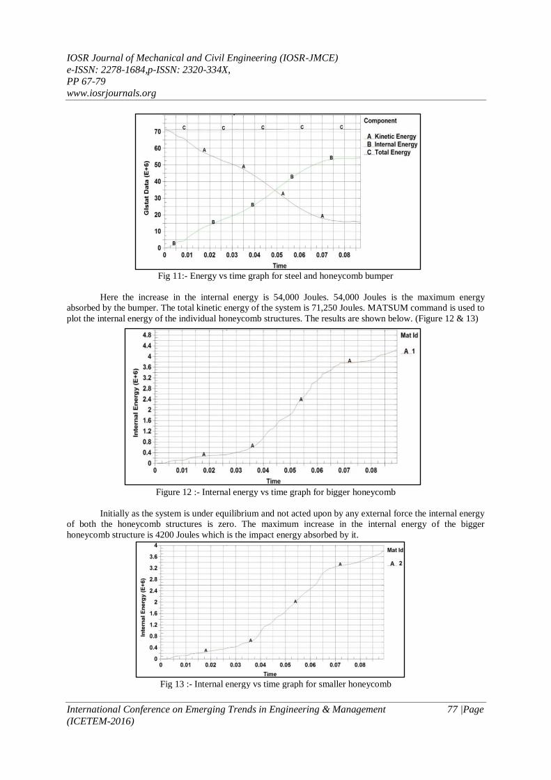
Fig 11:- Energy vs time graph for steel and honeycomb bumper
Here the increase in the internal energy is 54,000 Joules. 54,000 Joules is the maximum energy
absorbed by the bumper. The total kinetic energy of the system is 71,250 Joules. MATSUM command is used to
plot the internal energy of the individual honeycomb structures. The results are shown below. (Figure 12 & 13)
Figure 12 :- Internal energy vs time graph for bigger honeycomb
Initially as the system is under equilibrium and not acted upon by any external force the internal energy
of both the honeycomb structures is zero. The maximum increase in the internal energy of the bigger
honeycomb structure is 4200 Joules which is the impact energy absorbed by it.
Fig 13 :- Internal energy vs time graph for smaller honeycomb
IOSR Journal of Mechanical and Civil Engineering (IOSR-JMCE)
e-ISSN: 2278-1684,p-ISSN: 2320-334X,
PP 67-79
www.iosrjournals.org
International Conference on Emerging Trends in Engineering & Management 78 |Page
(ICETEM-2016)
The maximum increase in internal energy of the smaller honeycomb structure is 3800 joules. The total energy
absorbed by the combined honeycomb structures are 7800 Joules.
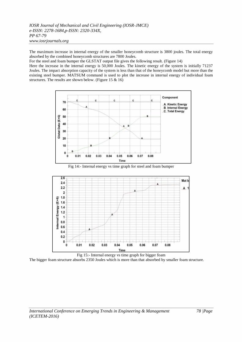
For the steel and foam bumper the GLSTAT output file gives the following result. (Figure 14)
Here the increase in the internal energy is 50,000 Joules. The kinetic energy of the system is initially 71237
Joules. The impact absorption capacity of the system is less than that of the honeycomb model but more than the
existing steel bumper. MATSUM command is used to plot the increase in internal energy of individual foam
structures. The results are shown below. (Figure 15 & 16)
Fig 15:- Internal energy vs time graph for bigger foam
The bigger foam structure absorbs 2350 Joules which is more than that absorbed by smaller foam structure.
Fig 14:- Internal energy vs time graph for steel and foam bumper
IOSR Journal of Mechanical and Civil Engineering (IOSR-JMCE)
e-ISSN: 2278-1684,p-ISSN: 2320-334X,
PP 67-79
www.iosrjournals.org
International Conference on Emerging Trends in Engineering & Management 79 |Page
(ICETEM-2016)
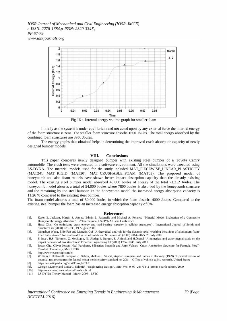
Fig 16 :- Internal energy vs time graph for smaller foam
Initially as the system is under equilibrium and not acted upon by any external force the internal energy
of the foam structure is zero. The smaller foam structure absorbs 1600 Joules. The total energy absorbed by the
combined foam structures are 3950 Joules.
The energy graphs thus obtained helps in determining the improved crash absorption capacity of newly
designed bumper models.
VIII. Conclusions This paper compares newly designed bumper with existing steel bumper of a Toyota Camry
automobile. The crash tests were executed in a software environment. All the simulations were executed using
LS-DYNA. The material models used for the study included MAT_PIECEWISE_LINEAR_PLASTICITY
(MAT24), MAT_RIGID (MAT20), MAT_CRUSHABLE_FOAM (MAT63). The proposed model of
honeycomb and also foam models have shown better impact absorption capacity than the already existing
model. The existing steel bumper model absorbed 46,000 Joules of energy of the total 71,212 Joules. The
honeycomb model absorbs a total of 54,000 Joules where 7800 Joules is absorbed by the honeycomb structure
and the remaining by the steel bumper. In the honeycomb model the increased energy absorption capacity is
11.26 % compared to the existing steel bumper.
The foam model absorbs a total of 50,000 Joules in which the foam absorbs 4000 Joules. Compared to the
existing steel bumper the foam has an increased energy absorption capacity of 6%.
References [1]. Karen E. Jackson, Martin S. Annett, Edwin L. Fasanella and Michael A. Polanco “Material Model Evaluation of a Composite
Honeycomb Energy Absorber”, 12thInternational LS-DYNA Users Conference.
[2]. Herzl Chai “On optimizing crash energy and load-bearing capacity in cellular structures” , International Journal of Solids and
Structures 45 (2008) 528–539, 19 August 2008
[3]. Qingchun Wang, Zijie Fan and Liangjin Gui “A theoretical analysis for the dynamic axial crushing behaviour of aluminium foam-
filled hat sections”, International Journal of Solids and Structures 43 (2006) 2064–2075, 25 July 2006
[4]. F. Ince , H.S. Türkmen, Z. Mecitoglu, N. Uludag, i. Durgun, E. Altinok and H.Örenel “A numerical and experimental study on the
impact behavior of box structures” Procedia Engineering 10 (2011) 1736–1741, July 2011
[5]. Bryan Chu, Oliver Jetson, Neal Parkhurst, Sébastien Pinauldt and Jorre Valeart “Crash Absorption Structure for Formula Ford”-
Cranfield University, March 2007
[6]. http://www.euroncap.com/en
[7]. William t. Hollowell, hampton c. Gabler, sheldon l. Stucki, stephen summers and James r. Hackney (1999) “Updated review of
potential test procedures for federal motor vehicle safety standard no. 208“ – Office of vehicle safety research, United States
[8]. https://en.wikipedia.org/wiki/Euro_NCAP
[9]. George E.Dieter and Linda C. Schmidt “Engineering Design”, ISBN 978–0–07–283703–2 (1988) Fourth edition, 2009
[10]. http://www.ncac.gwu.edu/vml/models.html
[11]. LS-DYNA Theory Manual - March 2006 - LSTC