Embed Size (px)
Citation preview
IOSR Journal of Mechanical and Civil Engineering (IOSR-JMCE)
e-ISSN: 2278-1684,p-ISSN: 2320-334X, Volume 13, Issue 5 Ver. I (Sep. - Oct. 2016), PP 07-20
www.iosrjournals.org
DOI: 10.9790/1684-1305010720 www.iosrjournals.org 7 | Page
Weight Optimization of Laminated Hook by Topological
Approach
Kiran Lanjekar#Amol N Patil
#Department of Mechanical Engineering, Dr. D. Y. Patil School of engineering, Charholi(Bk), Pune-412105,
Savitribai Phule Pune University.
Abstract: Laminated hooks are widely used in steel industry. Due to its high load carrying capacity they are
use for loading and unloading of material in heavy steel industry. Laminated hook got its name from the process
of manufacturing it. they are made of plates which are rivets together. In industry when continuous and
unloading occur the failure of hook take place, but in laminated hook when crack or faults occurs the faulty
plate can replace by the new one this reduces time and cost. In this project we will calculate the bending stress
occurred in hook and the factures effecting its life Weight optimization of hook using topological approach it's
taken in to consideration. Topological approach of weight optimization, in this weight will be reduce in area
where more stress is present. Simulation of the hook is done using topological approach. model is created, then
meshing is done, FEA analysis(ANSYS 14.0) carried out. The geometry which will obtain at the end of the
simulation, the dimension will be consider and scaled prototype is manufacture. Testing of the laminated hook is
done on UTM.
Keywords: Laminated hook, Weight optimization, Stress concentration, ANSYS.
I. Introduction Laminated hooks are the components which are generally used to lift the heavy load in industries and
constructional work. A crane hook is usually equipped with a safety latch to prevent the disengagement of the
lifting rope to which the load is being attach. Use for transport, construction and manufacturing industries
Laminated hooks are widely used in Steel industry ( ferrous and non-ferrous). They are use for lifting and
pouring of hot metal ladles. laminated hook are made of plates which are rivet together and form a combine
hook .
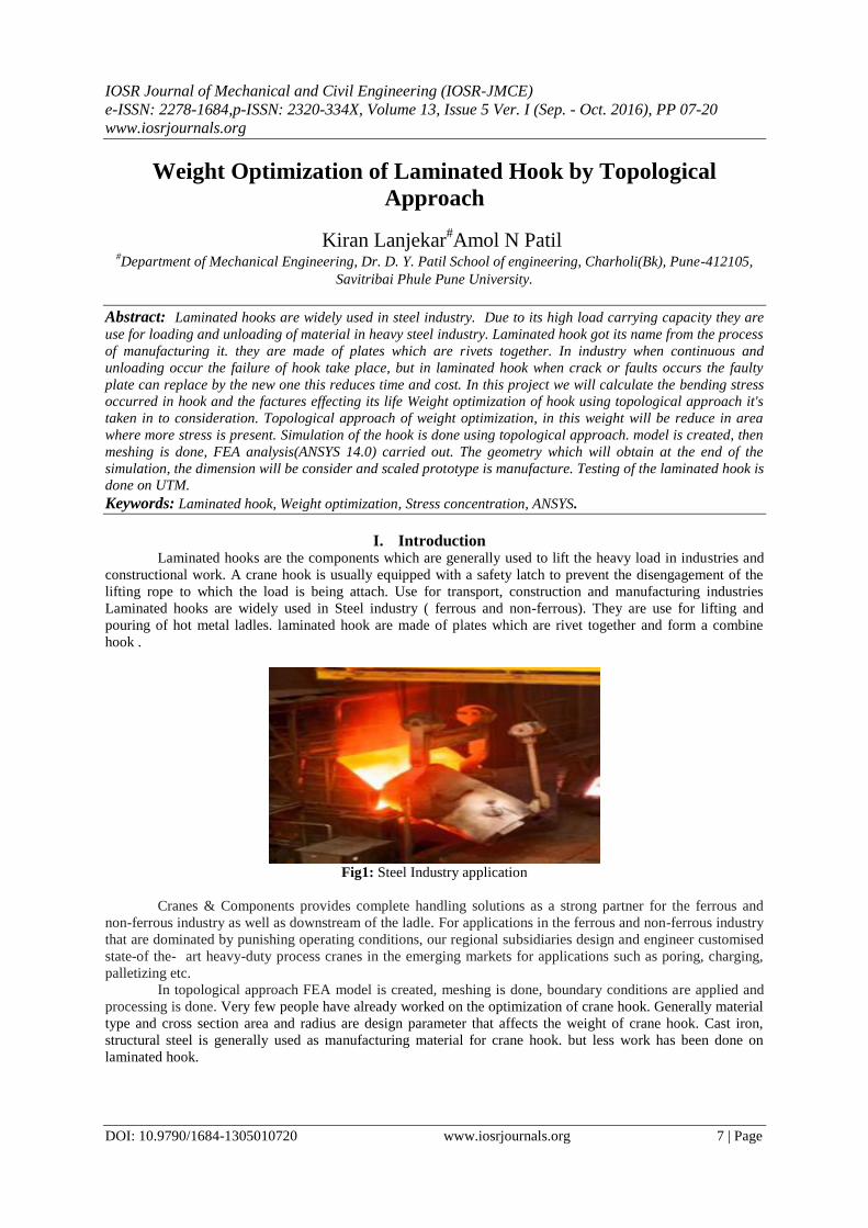
Fig1: Steel Industry application
Cranes & Components provides complete handling solutions as a strong partner for the ferrous and
non-ferrous industry as well as downstream of the ladle. For applications in the ferrous and non-ferrous industry
that are dominated by punishing operating conditions, our regional subsidiaries design and engineer customised
state-of the- art heavy-duty process cranes in the emerging markets for applications such as poring, charging,
palletizing etc.
In topological approach FEA model is created, meshing is done, boundary conditions are applied and
processing is done. Very few people have already worked on the optimization of crane hook. Generally material
type and cross section area and radius are design parameter that affects the weight of crane hook. Cast iron,
structural steel is generally used as manufacturing material for crane hook. but less work has been done on
laminated hook.

Weight Optimization of Laminated Hook by Topological Approach
DOI: 10.9790/1684-1305010720 www.iosrjournals.org 8 | Page
II. Literature Review The comparative study by Mr. A Gopichand. Et al. [1] has shown by using Taguchi method hook can
be optimization of design parameters. For minimum Von misses stresses optimum combination of input
parameter are consider. They had found minimum radius for von misses stresses Ram Krishna rathour. et al. [2]
has worked on a general approach for the multiple responses. Algorithm are used for various regression. They
had found the correlation in response function and control function.
Nishant soni et al. [3] has worked on the optimization of low carbon steel for its self-weight. The self-
weight and component load coming on the crane–hook hence he worked with objective of the optimization of
the mass for cane hook-under the effect of static load comprising the peak pressure load. He used finite element
analysis for the shape optimization of crane hook as well as for validation of final geometry. He also considered
geometry and manufacturing constrain during optimization process and results shows that optimized cane hook
is 14% lighter then original crane hook.
Chetan N. Benkar.et al. [4] worked on crane hook for the optimization. He estimated the stress pattern
of crane hook in its loaded condition by preparing a solid model with the help of ANSYS 14 workbench. By
considering various cross sectional area he obtained real time pattern of stress concentration with the help of 3-
D model of crane hook. His comparative study shows that the changes in result for different topology of cross
section for same cross section area. He calculated stress pattern for various cross section topology such as
rectangular, triangular, trapezoidal, and circular by keeping the area constant and found that rectangular cross
sectional area gives minimum stress and deformation level.
Rashmi Uddanwadiker.et.al. [5] has calculated the stress pattern produced due to the load on hook. He
compared the analytical result of stress and the stress estimated from the FEM analysis and found that there was
8.26% percent error between them. He found that possible reason for the variation is due to the assumption that
1) loading is considered as point loading in analytical calculation while it is taken on a bunch of nodes in
ANSYS.2) cross section area s assumed to be trapezoidal and 3) plane section remains plane after deformation.
His whole study is an initiative to establish a FEA procedure, by validating the results with the help of photo
elasticity. Photo elasticity test is based on the property of birefringence. From the analysis he found the area at
which high stress concentration occurs. For the design improvement if the inner side of hook at the portion of
maximum stress is widened then the stress will get reduced. He estimated that the stress is reduced up to 17% if
the thickness of the inner curvature is reduced by 3mm.
C. Oktay Azeloglu.et al. [6] has studied the method for the calculation of stress based on the different
assumption. First of these method is approximate calculation method and in this method curvature of the hook is
neglected and calculations are based on a straight beam. He adopted Timoshenko‟s curved theory and Bach
approximation on the simple hooks calculation. He used finite element method to estimate the stress and
compared it with different method.
M. Shaban. et al [7] prepared a solid model of crane hook to estimate the pattern of stress in the crane
hook. They used ABAQUS software and obtained real time pattern of stress concentration. Acrylic model is
used to verify the stress distribution pattern. By estimating the the stress concentration area, shape modification
is possible to maximise the working life and to minimise the failure. The whole work is a step to form a FEA
procedure, by validating the results, for the calculation of stresses. The value and location is very much
important factor in reducing the failure. If the inner curvature of hook is widened the
Takuma Nishimura.et al. [8] studied damage factor estimation of crane hooks to recognise the tendency
of the load condition. They used FEM to estimate the relation between the load condition and its deformation.
They get the result from the work that the load condition lies between the most downward point and the tip-end
stress will be reduced. For complicated mechanical element it is suitable to use caustic method. In caustic
method several small several holes are drilled to predict accurate stress value. point, the direction is toward the
gravity direction. First, load –deformation database that has the relation between the load condition of crane
hook and its deformation using numerical calculation is constructed. After the completion of study they found
that load acts in downward position and tip –end position and load direction is not downward normal in
damaged hook.
Santosh Sahu.et al. [9] made a model of crane hook of trapezoidal using CATIA V5R20.Then
estimated the location of stress after Appling the 2 ton load using FEM. They also analysed the effect of
variation in length of two parallel sides of trapezoidal hook on stress.
Apeksha K Patel.et al. [10] has worked on reduction of weight of girder which has reduced the cost of
girder and also life of girder is increased. They made a mathematical design for crane component by using
ANSYS workbench V12.They also optimized hook by using Trapezoidal cross sectional area.
Pradyumnakeshrimaharana. [11] has estimated hook dimensions for various cross section topology by
keeping the depth and cross section area. He concludes from his work that the trapezoidal section was lest
stressed.
Weight Optimization of Laminated Hook by Topological Approach
DOI: 10.9790/1684-1305010720 www.iosrjournals.org 9 | Page
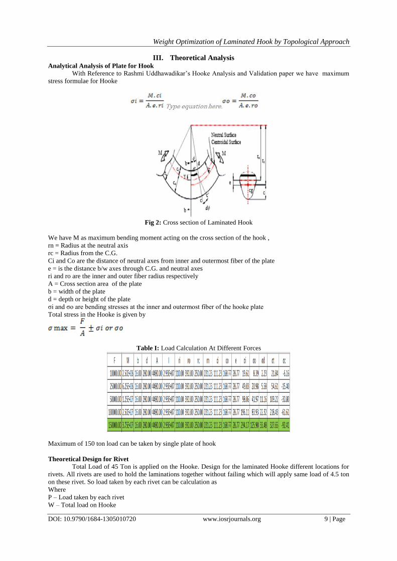
III. Theoretical Analysis Analytical Analysis of Plate for Hook
With Reference to Rashmi Uddhawadikar’s Hooke Analysis and Validation paper we have maximum
stress formulae for Hooke
Fig 2: Cross section of Laminated Hook
We have M as maximum bending moment acting on the cross section of the hook ,
rn = Radius at the neutral axis
rc = Radius from the C.G.
Ci and Co are the distance of neutral axes from inner and outermost fiber of the plate
e = is the distance b/w axes through C.G. and neutral axes
ri and ro are the inner and outer fiber radius respectively
A = Cross section area of the plate
b = width of the plate
d = depth or height of the plate
σi and σo are bending stresses at the inner and outermost fiber of the hooke plate
Total stress in the Hooke is given by
Table I: Load Calculation At Different Forces
Maximum of 150 ton load can be taken by single plate of hook
Theoretical Design for Rivet
Total Load of 45 Ton is applied on the Hooke. Design for the laminated Hooke different locations for
rivets. All rivets are used to hold the laminations together without failing which will apply same load of 4.5 ton
on these rivet. So load taken by each rivet can be calculation as
Where
P – Load taken by each rivet
W – Total load on Hooke

Weight Optimization of Laminated Hook by Topological Approach
DOI: 10.9790/1684-1305010720 www.iosrjournals.org 10 | Page
N – Number of Rivets
We know that P = 45000 kg
Now considering maximum g value as 10 mm/s2
We get
W = 45000 × 10
W = 450000 N
P = 450000 /N
A = Area of rivet
Maximum Shear stress allowed in rivet material is given by material properties for rivet aluminum alloy
Elastic Modulous – 72 GPa
Yeild strength – 69 MPa
Tensilet Strength – 179 MPa
Shear Strength ( Ss) – 124 MPa
Poison’s Ration – 0.33
Considering Factor of safety (FOS) as 3 maximum allowable shearstress is
Sy = 41 MPa
Shear Stress Taken By Rivets
41 =
Considering 13 number of rivets as per assumption in laminated hooke design.
N - 13
A = 422.1388
Where r – radius of rivet
Substituting the values in the formulae above we get
r = 11.59 mm
So we have selected 13 rivets of nominal diameter 25 mm which is closest to the answer we have got.
IV. Finite Element Analysis The finite element analysis (FEA) is a computational technique used to obtain approximate solution of
boundary value problems in engineering. Simply stated, a boundary value problem is mathematical problem in
which one or more dependent variables must satisfy a differential equation everywhere within a known domain
of independent variables and satisfy specific conditions on the boundary of the domain. The static structural
analysis of FE 410 W hot rolled steel plate laminated Hooke is done by finite element analysis using ANSYS 16
software. The properties of the material used are given in the table below. The analysis is done on a 3d model.
Meshing( computational grid): SOLID 95
Mesh size: 2mm
No of nodes: 20 nodes
1 node =3 dof (translational)
Table II: Properties Used in Fea Material Property Notation EN9 Unit
Modulus of Elasticity E 2.06 x 10⁵ MPa
Poisson Ratio v 0.3 -
Density P 7850 Kg/m3
Tensile Strength Syt 410 MPa
There are certain common steps in formulating a finite element analysis of a physical problem, whether
structural, fluid flow, heat transfer, vibration and some other problem. These steps are usually embodied in
commercial finite element software packages. There are three main steps, namely: preprocessing, solution and
post processing. The preprocessing (model definition) step is critical. This step includes; define the geometric
domain of the problem, the element types to be used, the material properties of the elements, the geometric
properties of the elements (length, area and the like), the element connectivity (mesh the model), the physical
constraints (boundary conditions) and the loadings. The next step is solution, in this step the governing algebraic

Weight Optimization of Laminated Hook by Topological Approach
DOI: 10.9790/1684-1305010720 www.iosrjournals.org 11 | Page
equations in matrix form and computes the unknown value of the primary field variables is assembled. Actually
the features in this step such as matrix manipulation, numerical integration and equation solving are carried out
automatically by commercial software. The final step is post processing, the analysis and evaluation of the result
is conducted in this step. The laminated Hooke to be optimized is shown below. Also list of the parts in the
assembly is also given below.
According to analytical solutions, it has been calculated that the safe operating load on the given design
of laminated Hooke model is 150000 Newton. To reduce manufacturing expenses of testing model is to be
scaled by 0.1 in all the dimensions. As the stress is function of area which is square of the dimensional scale and
loading. We have to scale loading by 0.01 for accommodating the scaling down the dimensions. So loading used
per plate will be 1500 N . As we are using three plates laminated together design the safe load taken by those
will be 4500 N
Fig 2: Assembly of laminated Hooke
While building FEA model laminated plate has been modelled using shell module with thickness is
given as a property of the plate. Element type 181 is used for meshing the shell model. Rivets are modelled as
solid model and Element type 185 is used for meshing them. Figure below shows the meshed model for the
assembly. Standard element size of 1 mm is used for the good results in the analysis
Fig 3: Meshed model laminated Hooke 1
Meshed model of chain link 1 is shown in Fig. The chain has been meshed by using rectangular grid. A
material property for FE 410 W has been entered as an input. The size of mesh is taken as 1mm
Fig 4:Static load applied
Weight Optimization of Laminated Hook by Topological Approach
DOI: 10.9790/1684-1305010720 www.iosrjournals.org 12 | Page
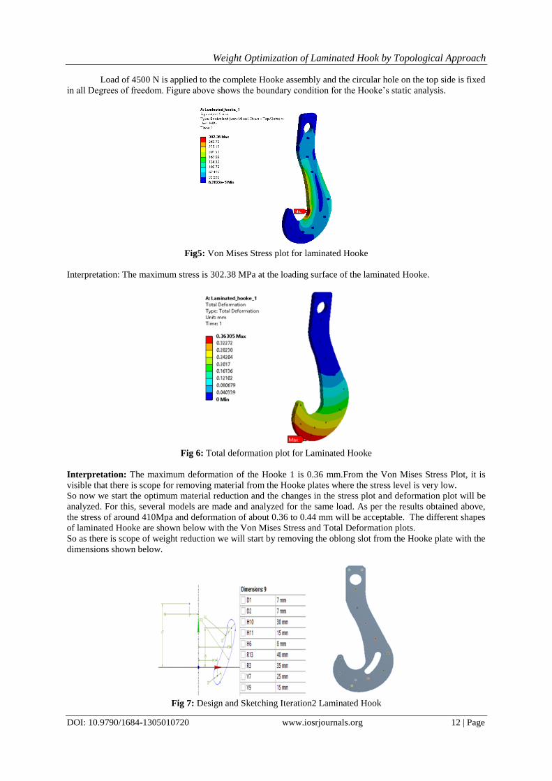
Load of 4500 N is applied to the complete Hooke assembly and the circular hole on the top side is fixed
in all Degrees of freedom. Figure above shows the boundary condition for the Hooke’s static analysis.
Fig5: Von Mises Stress plot for laminated Hooke
Interpretation: The maximum stress is 302.38 MPa at the loading surface of the laminated Hooke.
Fig 6: Total deformation plot for Laminated Hooke
Interpretation: The maximum deformation of the Hooke 1 is 0.36 mm.From the Von Mises Stress Plot, it is
visible that there is scope for removing material from the Hooke plates where the stress level is very low.
So now we start the optimum material reduction and the changes in the stress plot and deformation plot will be
analyzed. For this, several models are made and analyzed for the same load. As per the results obtained above,
the stress of around 410Mpa and deformation of about 0.36 to 0.44 mm will be acceptable. The different shapes
of laminated Hooke are shown below with the Von Mises Stress and Total Deformation plots.
So as there is scope of weight reduction we will start by removing the oblong slot from the Hooke plate with the
dimensions shown below.
Fig 7: Design and Sketching Iteration2 Laminated Hook
Weight Optimization of Laminated Hook by Topological Approach
DOI: 10.9790/1684-1305010720 www.iosrjournals.org 13 | Page
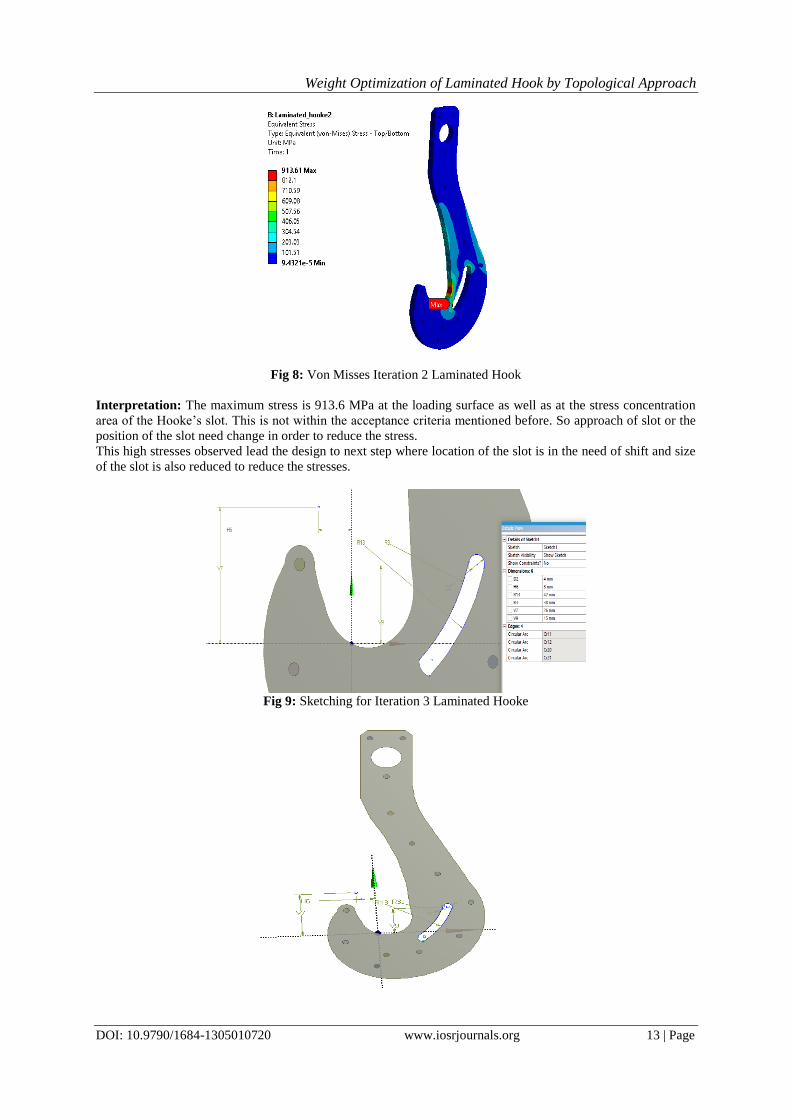
Fig 8: Von Misses Iteration 2 Laminated Hook
Interpretation: The maximum stress is 913.6 MPa at the loading surface as well as at the stress concentration
area of the Hooke’s slot. This is not within the acceptance criteria mentioned before. So approach of slot or the
position of the slot need change in order to reduce the stress.
This high stresses observed lead the design to next step where location of the slot is in the need of shift and size
of the slot is also reduced to reduce the stresses.
Fig 9: Sketching for Iteration 3 Laminated Hooke

Weight Optimization of Laminated Hook by Topological Approach
DOI: 10.9790/1684-1305010720 www.iosrjournals.org 14 | Page
Fig11: Von Mises Plot of Iteration 3
Interpretation: The maximum stress is 646.26 Mpa at the loading surface as well as at the stress concentration
area of the Hooke’s slot. This is still not within the acceptance criteria mentioned but it is reduced as compared
to the previous iteration.
Fig 12: Total Deformation of shape 2
Interpretation: The maximum deformation of theiteration 3 shape is observed as 0.42 mm which is again not
within the acceptance criteria for the laminated Hooke.
The Stress and total deformation plot show that the maximum stress is observed at the oblong slot
smaller radius section which is due to stress concentration. To reduce the stress concentration it is required to
increase the small radius curves. So in the next iteration try has been given to reduce the stresses at the stress
concentration location by increasing the size of the slot.
Iteration 1 assembly weight 0.1779
Iteration 8 weight 0.16061
% reduction in assembly weight 9.71
Weight Optimization of Laminated Hook by Topological Approach
DOI: 10.9790/1684-1305010720 www.iosrjournals.org 15 | Page
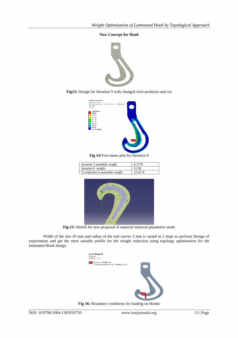
New Concept for Hook
Fig13: Design for Iteration 9 with changed rivet positions and cut
Fig 14:Von mises plot for Iteration 8
Iteration 1 assembly weight 0.1779
Iteration 8 weight 0.138
% reduction in assembly weight 22.42 %
Fig 15: Sketch for new proposal of material removal parametric study
Width of the slot 10 mm and radius of the end curves 3 mm is varied in 2 steps to perform Design of
experiments and get the most suitable profile for the weight reduction using topology optimization for the
laminated Hook design.
Fig 16: Boundary conditions for loading on Hooke
Weight Optimization of Laminated Hook by Topological Approach
DOI: 10.9790/1684-1305010720 www.iosrjournals.org 16 | Page
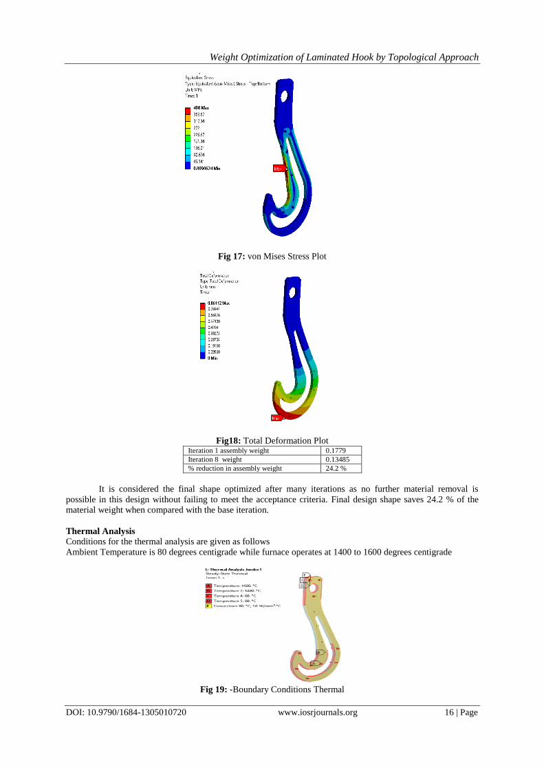
Fig 17: von Mises Stress Plot
Fig18: Total Deformation Plot
Iteration 1 assembly weight 0.1779
Iteration 8 weight 0.13485
% reduction in assembly weight 24.2 %
It is considered the final shape optimized after many iterations as no further material removal is
possible in this design without failing to meet the acceptance criteria. Final design shape saves 24.2 % of the
material weight when compared with the base iteration.
Thermal Analysis
Conditions for the thermal analysis are given as follows
Ambient Temperature is 80 degrees centigrade while furnace operates at 1400 to 1600 degrees centigrade
Fig 19: -Boundary Conditions Thermal
Weight Optimization of Laminated Hook by Topological Approach
DOI: 10.9790/1684-1305010720 www.iosrjournals.org 17 | Page
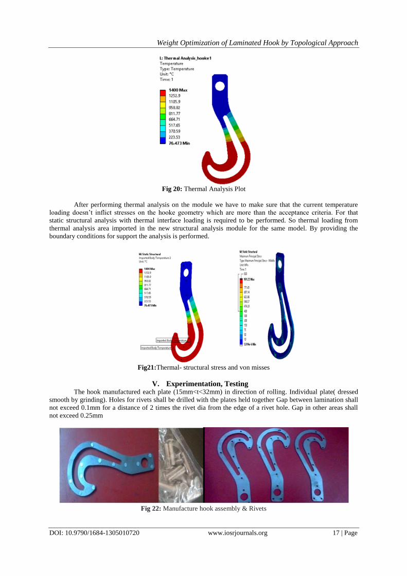
Fig 20: Thermal Analysis Plot
After performing thermal analysis on the module we have to make sure that the current temperature
loading doesn’t inflict stresses on the hooke geometry which are more than the acceptance criteria. For that
static structural analysis with thermal interface loading is required to be performed. So thermal loading from
thermal analysis area imported in the new structural analysis module for the same model. By providing the
boundary conditions for support the analysis is performed.
Fig21:Thermal- structural stress and von misses
V. Experimentation, Testing The hook manufactured each plate (15mm<t<32mm) in direction of rolling. Individual plate( dressed
smooth by grinding). Holes for rivets shall be drilled with the plates held together Gap between lamination shall
not exceed 0.1mm for a distance of 2 times the rivet dia from the edge of a rivet hole. Gap in other areas shall
not exceed 0.25mm
Fig 22: Manufacture hook assembly & Rivets
Weight Optimization of Laminated Hook by Topological Approach
DOI: 10.9790/1684-1305010720 www.iosrjournals.org 18 | Page
Fig 23: Experimental setup (on UTM)
For experimental testing of laminated hook a Universal Testing Machine of 10tonne capacity is
selected. Hook will be clamped between jaws of UTM by using manufactured fixture. Strain gauges will use for
measurement of displacement.
Fig 24: Photograph of complete experimental setup
The above fig. shows the photograph of complete experimental setup. Computer is used for operating
the UTM and for recording the load v/s displacement data with respect to time. The UTM is fully automatic.
The hydraulic oil pressure is given from 0N then after it is increase 100 N/sec till the laminated hook fail. By
using the recorded data software generate the graph simultaneously against the load in N on Y-axis and
displacement in mm on X-axis. The software automatically records peak force taken by hook
Behavior of Laminated hook plate:- Experimental testing of laminated hook of material has been
performed on Universal Testing Machine.
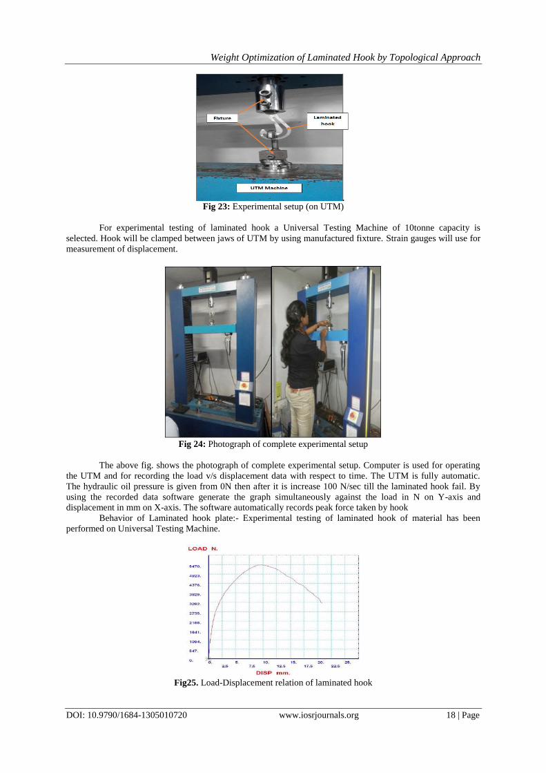
Fig25. Load-Displacement relation of laminated hook
Weight Optimization of Laminated Hook by Topological Approach
DOI: 10.9790/1684-1305010720 www.iosrjournals.org 19 | Page
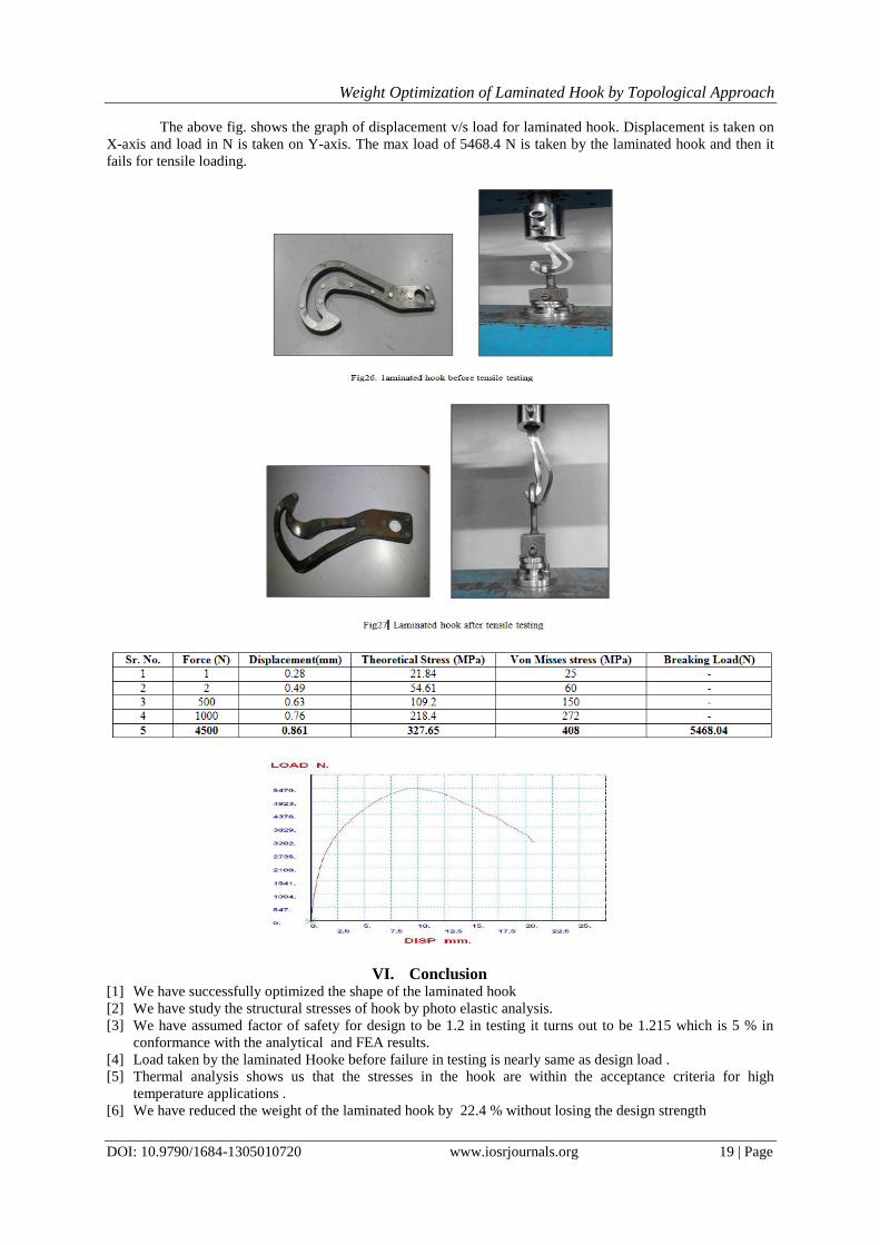
The above fig. shows the graph of displacement v/s load for laminated hook. Displacement is taken on
X-axis and load in N is taken on Y-axis. The max load of 5468.4 N is taken by the laminated hook and then it
fails for tensile loading.
VI. Conclusion [1] We have successfully optimized the shape of the laminated hook
[2] We have study the structural stresses of hook by photo elastic analysis.
[3] We have assumed factor of safety for design to be 1.2 in testing it turns out to be 1.215 which is 5 % in
conformance with the analytical and FEA results.
[4] Load taken by the laminated Hooke before failure in testing is nearly same as design load .
[5] Thermal analysis shows us that the stresses in the hook are within the acceptance criteria for high
temperature applications .
[6] We have reduced the weight of the laminated hook by 22.4 % without losing the design strength
Weight Optimization of Laminated Hook by Topological Approach
DOI: 10.9790/1684-1305010720 www.iosrjournals.org 20 | Page
Acknowledgment I take this opportunity to thanks Prof. A. N. Patil (Guide), Prof A .B. Gaikwad & Mr. Deepak Desai for
valuable guidance and for providing all the necessary facilities, which were indispensable in completion of this
work. Also I sincerely thanks to all the authors who worked on Material Handling Techniques.
References [1] Mr. A. Gopichand, Ms. R. V. S. Lakshmi, Mr. B. Maheshkrishna “Optimization of design parameter for crane hook
using taguchi method” in international journals of innovative research in science ,engineering and technology, vol. 2,
Dec 2013, ISSN: 2319-8753.
[2] Ram Krishna Rathore, Amit Sarda and Rituraj Chandrakar, “An approach to optimize ANN Meta Model with Multi
Objective Genetic Algorithm for Multi-Disciplinary shape Optimization” in International journal of soft computing and
Engineering, Volume-2, Issue-1, March 2012, ISSN: 2231-2307.
[3] Nishant soni, “crane-hook shapes optimization and thermal analysis using finite element too” in international journal of
advanced and innovation research”, ISSN: 2278-7844.
[4] Chetan N. Benkar, Dr. N. A. Wankhade “Finite Element stress Analysis of Crane Hook With Different Cross Sections”
in International Journal For Technological Research In Engineering, volume 1, Issue 9,May-2014, ISSN 2347-4718.
[5] Rasmi Uddanwadikar“Stress Analysis Of Crane Hook and Validation by Photo-Elasticity” in Scientific Research, 2011,
ISSN 935-941
[6] C. Oktay Azeloglu, Onur Alpay“Investigation of a Lifting Hook with Different Method, Verification of the Distribution
with Photo elasticity Experiments”, in electronic journal of Machine Technology, vol-6, 2009, ISSN 1304-4141.
[7] M. Shaban, M. I. Mohamed, A. E. Abuelezz and T. Khalifa, “Determination Of Stress Distribution in Crane Hook by
Caustic” in International Journal of Innovative Research in science, Engineering and Technology, Vol. 2 Issue 5, May
2013, ISSN: 2319-8753.
[8] Takuma Nishimura, Takao Muromaki, Kazuyuki Hanahara, “Damage factor Estimation of Crane Hook (A database
approach with Image, Knowledge and simulation)” in Research publishing services, 2010, ISBN: 978-981-08-5118-7.
[9] Santosh Sahu, Ritesh Dewangan, Manas Patnaik, Narendra Yadav,“Study of Crane Hook Having Trapezoidal Section
by Finite Element Method& Design Experiments” in International Journal of Modern Engineering Research, vol.
2.Issue-4,July-Aug 2012,pp-2779-2781.
[10] Apeksha. K. Patel, Prof. V. K. Jani, “Design and Dynamic Analysis of 70T Double Girder Electrical Overhead Crane”
in Journal of Information, Knowledge and Research in Mechanical Engineering Vol.2, Oct-2013, ISSN-975-668X.
[11] Pradyumnakesharimaharana, “Computer Aided Analysis and Design of Hoisting Mechanism of an EOT Crane”,
.Thesis, National Institute of Technology Rourkela, May-2012.
[12] E.Narvydas, N.Puodziuniene, “Circumferential Stress Concentration Factor at the Asymmetric shallow Notches Of The
lifting hook of trapezoidal cross-section” in Mechanika, vol. 18(2), 2012, ISSN 1392-1207.
[13] Specification for Laminated Ladle Hook, IPSS:1-08-009-83 DIN,15407