Embed Size (px)
Citation preview
The Hilli Episeyo FLNGThe world’s first converted floating liquefaction (FLNG) ship, the Hilli Episeyo, began its maiden voyage from the Keppel Shipyard in Singapore in mid-October 2017, traveling across the Indian Ocean and around Capetown, South Africa, to reach its final destination near Kribi, Cameroon in late November. The long journey, an estimated 8000 nautical miles, was completed in late November 2017.
The 125 000 m3 vessel was converted from a 1975 Moss LNG carrier to an FLNG terminal for Golar LNG by Keppel O&M, a
division of Keppel Shipyard Ltd. The Hilli Episeyo, which means Hope, will be deployed at the Sanaga offshore gas field, operated by Perenco and Société Nationale des Hydrocarbures (SNH), where it will process stranded gas into LNG and export it to a gas processing plant to feed the 216 MW Kribi Power Plant. It can provide about 2.4 million tpy of LNG. LNG production began in mid-March 2018.
Re-purposing an LNG carrier that has served its life is an art that consists of saving the hull and tanks and building the liquefaction process on the topside of the vessel. Designing and
Improving efficiency
at seaChris Campos, Chris Thomas, and John Goodrich, Ebara International Corporation – Cryodynamics,
USA, discuss current and future floating LNG projects and the role of expander design.
Figure 1. Golar Hilli Episeyo FLNG from the Keppel shipyard.
Reprinted from August 2018
fabricating a modularised and condensed LNG liquefaction terminal on a floating vessel is a new skill and an opportunity for future upstream suppliers. It requires a careful balance of practicality, technology, safety, and functionality as well as an understanding of the marine environment for operating at sea. Aside from the project’s commercial commitments, the engineering and design required is a technical feat.
Onshore versus offshoreThe argument for building liquefaction terminals onshore versus offshore continues in regards to the benefits and drawbacks of each. Perhaps there is no argument, but two different solutions to help solve market demand.
Unlike purpose-built new builds such as the Shell Prelude FLNG, Petronas FLNG, and even the Exmar FLRSU projects, the Hilli Episeyo FLNG is a conversion of existing technology to bring a solution to market quicker. Several joint partnerships were formed to develop the technology for this conversion including a liquefaction process to produce the LNG and a shipbuilder to undertake the challenge.
Changing expander design For the Hilli Episeyo, Ebara International Corporation – Cryodynamics, a wholly owned subsidiary of Elliott Company, developed a lower capacity liquid expander. Ebara Cryodynamics has nearly 20 years of experience developing and manufacturing liquid expanders for multiple LNG liquefaction processes, but this version required scaling of the process requirements for an offshore marine environment.
Ebara Cryodynamics installed its first cryogenic liquid expander at the Oman LNG plant in Qalhat near Sur as a replacement for the Joule-Thomson (JT) valve in the letdown process prior to LNG storage; as shown in Figure 2. Replacement of the JT valve with a cryogenic liquid expander has since increased LNG production by 3 – 5%. Subsequently, the additional LNG translates to a financial return that makes the liquid expander extremely attractive. Depending upon the price of LNG, the use of a liquid expander, and the resulting increase in production, can recover the cost of the equipment in less than six months.
The original design of the liquid expander mimicked the design of a submerged motor pump except that the liquid entered the inlet in a downward flow configuration. The original liquid expanders were also equipped with either a variable or fixed speed variable frequency drive (VFD). This matching of VFD equipment has become semi-standard in new liquefaction plants.
Given the constant price fluctuations in the modern LNG market, it is increasingly important for LNG equipment to be as flexible and efficient as possible. Since the first cryogenic liquid expander was developed, these units have been provided with the option of either a fixed speed unit (50 Hz or 60 Hz), or a VFD system. The variable speed operation is accomplished through the use of either a low or medium voltage variable speed drive unit, whereas a fixed speed unit’s RPM is set by the frequency of the plant power grid (3000 or 3600 RPM). A VFD allows the expander unit to be flexible and operate under changing process conditions and fluid densities, while still ensuring the generator outputs the correct frequency to the plant operating grid.
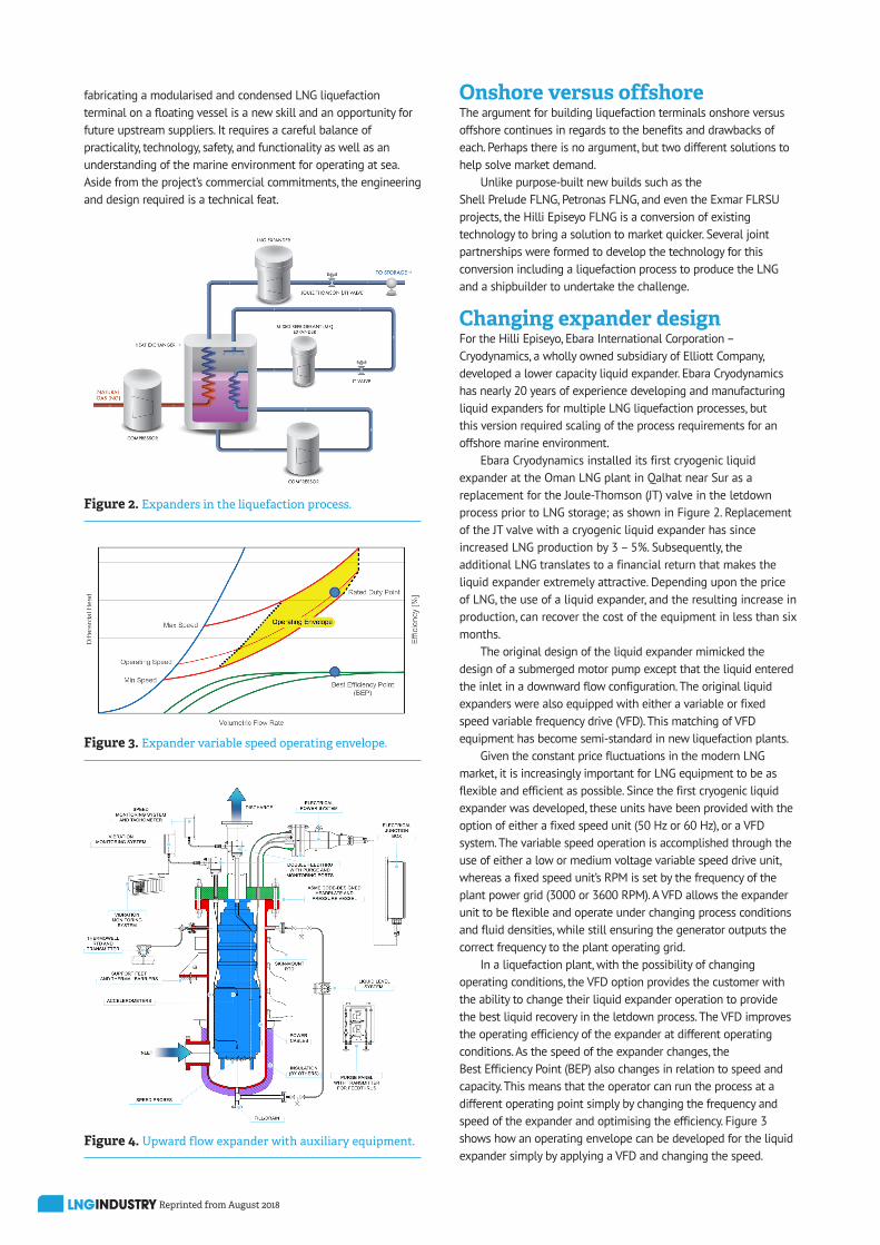
In a liquefaction plant, with the possibility of changing operating conditions, the VFD option provides the customer with the ability to change their liquid expander operation to provide the best liquid recovery in the letdown process. The VFD improves the operating efficiency of the expander at different operating conditions. As the speed of the expander changes, the Best Efficiency Point (BEP) also changes in relation to speed and capacity. This means that the operator can run the process at a different operating point simply by changing the frequency and speed of the expander and optimising the efficiency. Figure 3 shows how an operating envelope can be developed for the liquid expander simply by applying a VFD and changing the speed.
Figure 2. Expanders in the liquefaction process.
Figure 3. Expander variable speed operating envelope.
Figure 4. Upward flow expander with auxiliary equipment.
Reprinted from August 2018
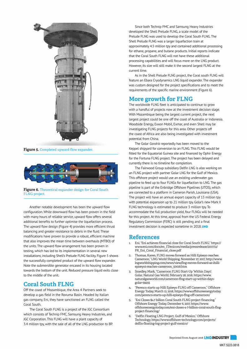
Another notable development has been the upward flow configuration. While downward flow has been proven in the field with many hours of reliable service, upward flow offers several additional benefits to further optimise the liquefaction process. The upward flow design (Figure 4) provides more efficient thrust balancing and greater resistance to debris in the fluid. These modifications have proven to provide a robust, efficient machine that also improves the mean time between overhauls (MTBO) of the units. The upward flow arrangement has been proven in testing, which has led to its implementation in several new installations, including Shell’s Prelude FLNG facility. Figure 5 shows the successfully completed product of the upward flow expander. Note the submersible generator encased in its housing located towards the bottom of the unit. Reduced pressure liquid exits close to the middle of the unit.
Coral South FLNGOff the coast of Mozambique, the Area 4 Partners seek to develop a gas field in the Rovuma Basin. Headed by Italian gas company, Eni, they have sanctioned an FLNG called the Coral South.
The Coral South FLNG is a project of the JGC Consortium which consists of Technip FMC, Samsung Heavy Industries, and JGC Corporation. This FLNG will have a plant capacity of 3.4 million tpy, with the sale of all of the LNG production to BP.
Since both Technip FMC and Samsung Heavy Industries developed the Shell Prelude FLNG, a scale model of the Prelude FLNG was used to develop the Coral South FLNG. The Shell Prelude FLNG was a larger liquefaction train at approximately 4.5 million tpy and contained additional processing for ethane, propane, and butane products. Initial reports indicate that the Coral South FLNG will not have these additional processing capabilities and will focus more on the LNG product. However, its size will still make it the second largest FLNG at the current time.
As in the Shell Prelude FLNG project, the Coral south FLNG will feature an Ebara Cryodynamics LNG liquid expander. The expander was custom designed for the project specifications and to meet the requirements of the specific marine environment (Figure 6).
More growth for FLNG The worldwide FLNG fleet is anticipated to continue to grow with a handful of projects now at the investment decision stage. With Mozambique being the largest current project, the next largest project could be one off the coast of Australia or Indonesia. Woodside Energy, Exxon Mobil, Exmar, and even Shell may be investigating FLNG projects for this area. Other projects off the coast of Africa are also being investigated with investment potential from China.
The Golar Gandria reportedly has been moved to the Keppel shipyard for conversion to an FLNG. This FLNG would be fitted for the Equatorial Guinea site and financed by Ophir Energy for the Fortuna FLNG project. The project has been delayed and currently there is no timeline for completion.
The Fairwood Group subsidiary Delfin LNG is also working on an FLNG project with partner Golar LNG for the Gulf of Mexico. This offshore project would use an existing underwater gas pipeline to feed up to four FLNGs for liquefaction to LNG. The gas pipeline is part of the Enbridge Offshore Pipelines (UTOS), which are connected to a platform in Cameron Parish, Louisiana (USA). The project will have an annual export capacity of 13 million tpy with potential expansion up to 21 million tpy. Golar’s new Mark II FLNG technology is estimated to produce 3 million tpy. To accommodate the full production yield, four FLNGs will be needed for this project. At this time, approval from the US Federal Energy Regulatory Commission (FERC) is still pending and a final investment decision is expected sometime in 2018.
References 1. Eni, “Eni achieves financial close for Coral South FLNG,” https://
www.eni.com/docs/en_IT/enicom/media/pressrelease/2017/12/PR_Eni_Coral_Financial_close.pdf
2. Thomas, Karen, FLNG moves forward as Hilli Episeyo reachesCameroon,” LNG World Shipping, November 27, 2017, http://www.lngworldshipping.com/news/view,flng-moves-forward-as-ihilli-episeyoi-reaches-cameroon_50018.htm
3. Smedley, Mark, “Cameroon FLNG Start-Up ‘Within Days’:Golar, Natural Gas World, February 28, 2018, https://www.naturalgasworld.com/cameroon-flng-start-up-within-days-golar-59255
4. “Perenco starts up Hilli Episeyo FLNG off Cameroon,” OffshoreEnergy Today, March 12, 2018, https://www.offshoreenergytoday.com/perenco-starts-up-hilli-episeyo-flng-off-cameroon/
5. “Eni Closes $4.7 billion Coral South FLNG project financing,”Offshore Energy Today, December 6, 2017, https://www.offshoreenergytoday.com/eni-closes-4-7-billion-coral-south-flng-project-financing/
6. “Delfin Floating LNG Project, Gulf of Mexico,” OffshoreTechnology, https://www.offshore-technology.com/projects/delfin-floating-lng-project-gulf-mexico/
Figure 5. Completed upward flow expander.
Figure 6. Theoretical expander design for Coral South FLNG project.
MKT.5223.0818


![ROBERT JAMES ELLIOTT CURRICULUM VITAE CITIZENSHIP ...haskayne.ucalgary.ca/.../robert-elliott-cv.pdf · R.J. Elliott – CV [September, 2006 - Page 1] ROBERT JAMES ELLIOTT CURRICULUM](https://img.pdfslide.us/doc/110x75/5fdc51cfa239fb15507e657b/robert-james-elliott-curriculum-vitae-citizenship-rj-elliott-a-cv-september.jpg)