Embed Size (px)
Citation preview

8/12/2019 Improvement of Heavy Oil Recovery in the VAPEX Process Using Montmorillonite Nanoclays
http://slidepdf.com/reader/full/improvement-of-heavy-oil-recovery-in-the-vapex-process-using-montmorillonite 1/12
Oil & Gas Science and Technology – Rev. IFP Energies nouvelles , Vol. 66 (2011), No. 6, pp. 1005-1016Copyright © 2011, IFP Energies nouvellesDOI: 10.2516/ogst/2011109
Improvement of Heavy Oil Recovery in the VAPEXProcess using Montmorillonite Nanoclays
K. Pourabdollah1*, A. Zarringhalam Moghaddam2, R. Kharrat 3 and B. Mokhtari1
1 Department of Chemical Engineering, Shahreza Branch, Islamic Azad University, Shahreza - Iran
2 Chemical Engineering Faculty, Tarbiat Modares University, Tehran - Iran
3 Petroleum University of Technology Research Center, Tehran - Iran
e-mail: [email protected] - [email protected] - [email protected] - [email protected]
* Corresponding author
Résumé – Amélioration de la récupération d’huile lourde par utilisation de nanoargiles de Montmorillonite
dans le procédé VAPEX – Dans cet article, on décrit l'utilisation de particules de nanoargile en tant
qu’adsorbant mobile dans des réservoirs d’huile afin d’adsorber les asphaltènes, réduire la viscosité de
l'huile et renforcer la dispersion. L’objectif de cet article consiste en la description d'une étude expérimen-
tale de récupération améliorée d’huile lourde par l’utilisation de nanoparticules in situ. Ce qui constitue
une première. En outre, deux méthodes d’analyse thermique (thermogravimétrie et analyse thermique dif-
férentielle) ont été utilisées pour analyser la teneur en asphaltène des résidus d’hydrocarbures dans les
chambres balayées au cours des procédés VAPEX nano-assisté et conventionnel. Les expériences ont été
réalisées en utilisant une huile lourde iranienne et du propane : le dispositif expérimental consistait en
deux cellules garnies de sable, l’une garnie uniquement avec des billes de verre en tant que milieu poreux
et l’autre avec des billes de verre et de la montmorillonite modifiée en tant que nanoargile ; les deux
avaient la même porosité et la même perméabilité. La teneur en asphaltène déposé dans les zones
balayées, le profil de propagation des chambres de vapeur ainsi que les taux de consommation de solvant
et de production d’huile ont été déterminés. Les résultats ont mis en évidence que la montmorillonite a
modifié l’hétérogénéité du milieu poreux et a conduit à former des percées accrues, à augmenter la sur-
face interfaciale solvant/bitume et à accélérer la production d’huile. Il s’est avéré que non seulement le
débit d’injection de solvant a été diminué, mais que la récupération d’huile lourde a également été sensi-
blement accrue de 30 (± 4) %.
Abstract – Improvement of Heavy Oil Recovery in the VAPEX Process using Montmorillonite
Nanoclays – In this paper, the nanoclay particles were introduced as mobile adsorbents in oil reservoirs to
adsorb the asphaltenes, reduce the viscosity and enhance the dispersion. The objective of this paper is
experimental investigation of enhanced heavy oil recovery using in situ nanoparticles for the first time.
Moreover, two thermal analysis methods (thermogravimetry and differential thermal analysis) were used
to analyze the asphaltene content of residue hydrocarbons in the swept chambers in nano-assisted and
conventional VAPEX processes. Experiments were carried out using Iranian heavy oil and propane: the
setup consisted of two sand-packed cells; one packed only with glass beads as the oil matrix and the other

8/12/2019 Improvement of Heavy Oil Recovery in the VAPEX Process Using Montmorillonite Nanoclays
http://slidepdf.com/reader/full/improvement-of-heavy-oil-recovery-in-the-vapex-process-using-montmorillonite 2/12
Oil & Gas Science and Technology – Rev. IFP Energies nouvelles, Vol. 66 (2011), No. 61006
North America1750 Gbbl
Europe16 Gbbl
Latin America1400 Gbbl
Africa47 Gbbl MiddleEast
135 Gbbl
Far East38 Gbbl
World resources: 4700 Gbbl
North America
1.3 Mbbl/d
Europe0.4 Mbbl/d
Latin America
2.8 Mbbl/d
Africa0.06 Mbbl/d MiddleEast
0.5 Mbbl/d
FSU600 to
0.3 Mbbl/d
Far East0.2 Mbbl/d
World 2003 production: 5.5 Mbbl/d
INTRODUCTION
The Importance of the VAPEX Process
The resources of heavy oil in the world are more than twice
those of conventional light crude oil. Saniere et al. illustrated
that from the available heavy oil only a fraction is extracted
by conventional methods [1]. Figure 1 shows the worldwide
heavy oil resources and production.
The quota of high-viscosity oil in total worldwide oil pro-duction is constantly growing. Large reserves of high-viscos-
ity oils are found in Canada, Venezuela, Mexico, the USA,
Russia, Kuwait and China [2]. Average heavy oil production
is now about 12% of total world oil production [3]. Different
categories of heavy crude are usually defined according to
their density and viscosity, as illustrated in Figure 2. Heavy
oils, which often result from bacterial oxidation of conven-
tional oils inside the reservoir rock, have different physical
and chemical properties, generally degraded: they have much
higher viscosity, higher heavy metals and higher sulfur and
nitrogen contents [4]. To reduce the viscosity, solvents are
frequently used to dilute heavy crudes. This is one of themost efficient methods in pipeline transportation of heavy
oils. Solvents are also injected into the reservoir for well
cleaning, stimulation, fracturing and, less frequently, for mis-
cible displacement [5].
A large amount of heavy oil is still trapped in reservoirs
after the traditional oil extraction, thus a number of enhanced
heavy oil recovery processes have been developed for
extracting the residual heavy oil [6].
Enhanced recovery processes for heavy oil are mainly
thermal, solvent-based and cold methods. In thermal methods
such as Steam-Assisted Gravity Drainage (SAGD),
Combustion Overhead Gravity Drainage (COGD), Cyclic
Steam Stimulation (CSS) and In Situ Combustion (ISC) or
Toe-to-Heel Air Injection (THAI), the viscosity is reduced byheating the reservoir, but the major problem is the heat loss
to adjacent formations. In cold methods such as Cold Heavy
Oil Production with Sands (CHOPS), water flooding, surface
mining and Gas-Assisted Gravity Drainage (GAGD), there is
no solvent or thermal consumption. However, solvent-based
methods such as Vapor Extraction (VAPEX) and the
Solvent-Aided Process (SAP) are preferred. Recently, some
interesting techniques and hybrid methods have been
patented such as combined Steam And Vapor Extraction
(SAVEX) and Radiofrequency-Assisted Gravity Drainage
(RASD) [7].
Abu-Khader defined the asphaltene constituents as asolubility class that was precipitated from petroleum,
heavy oil and bitumen by the addition of an excess of a liq-
uid paraffin hydrocarbon [8]. Mousavi-Dehghani reported
many factors which affect the asphaltene precipitation
with glass beads and modified montmorillonite as the nanoclay, while they had similar porosity and per-
meability. The content of deposited asphaltene in swept matrixes, the propagation pattern of vapor cham-
bers in heavy oil matrixes, and the rates of solvent consumption and oil production were determined. The
results elucidated that montmorillonite changed the matrix heterogeneity and led to forming enhanced
breakthroughs, to increasing the interfacial surface of vapor/bitumen and to accelerating the oil produc-
tion. It was found that not only was the rate of vapor injection diminished, but the heavy oil recovery was
also markedly enhanced by 30(±4)%.
Figure 1
Geographical distribution of heavy oil resources a) and its production b).
a) b)
FSU600 to
1450 Gbbl

8/12/2019 Improvement of Heavy Oil Recovery in the VAPEX Process Using Montmorillonite Nanoclays
http://slidepdf.com/reader/full/improvement-of-heavy-oil-recovery-in-the-vapex-process-using-montmorillonite 3/12
Heavy oils
Extra-heavy oils
Viscosity
Density
20°API
10°API
<10 000 cP >10 000 cP
Bitumen
inside a reservoir [9]. Das and Butler [10] and Kök et al.
[11] analyzed the asphaltene deposition by the VAPEX
process in a Hele-Shaw cell, while this work was carried
out in sand-packed cells. Moreover, the asphaltene move-
ment and its distribution were studied during the experi-
ment run.
The Importance of Nanoclays
The advantage of nanoparticles with respect to their applica-
tion is attributed to their nano-size, which strongly affects the
property changes in the bulk material. Depending on the aca-
demic source, there are four main groups of clays: kaolinite,
smectite, illite and chlorite. The term of nanoclay is attributed
only to the smectite family, which has a unique morphology,
featuring one dimension in the nanometer range. Therefore,
kaolinite, illite and chlorite are not included as nanoclays.
Montmorillonite (MMT), a member of the smectite family,
was discovered in 1847 in Montmorillon in the Vienne pre-
fecture of France, more than 50 years before the discovery of
bentonite in the US. MMT is 2:1 clay, meaning that it has 2
tetrahedral sheets sandwiching a central octahedral sheet. The
particles are plate-shaped with an average diameter of
approximately one micrometer. Individual platelet thick-
nesses are just one nanometer, but surface dimensions are
generally 300 to more than 600 nanometers, resulting in anunusually high aspect ratio.
A characteristic of MMT nanoclays, which makes them
special, is their interaction with the surrounding matrix. This
special interaction is based upon their modification method
and modifiers. MMTs with different structures reveal differ-
ent reactivity and hence, their modifications are varied.
Therefore, special characteristics of MMTs are dependent on
their structure, reactivity and modifiers, which are discussed
in the following.
The Structure of MMTs
As discussed above, according to Figure 3, MMT is one of
the smectite group, composed of silica tetrahedral sheets lay-
ered with an alumina octahedral sheet [12]. The imperfec-
tions of the MMT crystal lattice with the isomorphous substi-
tution induce a net surface negative charge that leads to the
adsorption of metals, cations and sulfur atoms in the inter-layer space and external surfaces. MMT also contains dan-
gling hydroxyl end-groups on the surfaces and has a large
specific surface area; it exhibits good adsorbability [13].
MMT's Reactivity
Masih et al. investigated the affinity of Na+MMT with the
modifier arsenic by preparing different types of iron species
[14]. There have been other studies conducted on the cation
exchange capacity of MMT [15]. Navratilova et al. studied
adsorption of two cationic surfactants, hexadecyl trimethyl
Figure 2
Schematic classification of heavy oils.
Tetrahedral sheet
9 . 6
Å
d
- s p a c i n g
Octahedral sheet
Tetrahedral sheet
Interlayer or gallery
Al, Fe, Mg, Li
OHOLi, Na, Rb, Cs
H2OH2O
H2OH2O
{
Figure 3
Schematic presentation of Montmorillonite structure.
1007K. Pourabdollah et al. / Improvement of Heavy Oil Recovery in the VAPEX Process using Montmorillonite Nanoclays

8/12/2019 Improvement of Heavy Oil Recovery in the VAPEX Process Using Montmorillonite Nanoclays
http://slidepdf.com/reader/full/improvement-of-heavy-oil-recovery-in-the-vapex-process-using-montmorillonite 4/12
Oil & Gas Science and Technology – Rev. IFP Energies nouvelles, Vol. 66 (2011), No. 61008
ammonium bromide and benzyl dimethyl hexadecyl ammo-
nium chloride, onto the samples of MMT [16]. Fusova inves-
tigated the intercalation of octadecylamine into the interlayer
space of MMT in relation to the quantity of added organic
substance [17]. Therefore, organically modified MMTs have
become an attractive class of organic/inorganic hybrids
because of their potential use in a wide range of applications
[18].
Modified MMTs
The adsorption hypothesis of modified MMT has been
reported by Lin et al. [19] and Rahman et al. [20] for adsorp-
tion of Bovine Serum Albumin (BSA) protein and crude oil
into the layered silicate MMT. Based upon Lin et al.'s [19]
suggested mechanism, the modified MMTs is prone to
adsorbing heavy oil asphaltenes and their micelles in their
interlayer spaces. Therefore, this tendency of MMTs to
adsorb the heavy oil asphaltenes was used to improve the rate
of the VAPEX process [21]. Figure 4 illustrates schemati-
cally the asphaltene substitutions into the layered Na+MMT.
Based upon these methods, in the present study MMTs
with d -spacing of 3.15 nm were used in order to adsorb
asphaltene into the MMT's spaces. The effects of MMTs on
the pattern and content of asphaltene adsorption and upgrad-
ing, the propagation pattern of the vapor chamber in a heavy
oil matrix, the rates of vapor consumption and oil production,
and the recovery factor were studied by comparing two sys-
tems, with and without MMTs.
Thermal Analysis of Crude Oil
Nowadays, much research is done to analyze the crude oil
components such as asphaltenes. In this regard, thermal
analysis has provided useful data [22-24]. Thermal analysis
is a group of instrumental methods for evaluating different
properties and the chemical composition of complex materi-
als by heating the sample at a given rate (normally 10-
50°C/min) at different pressures and compositions of the gas
medium. Thermogravimetry (TG), Differential Scanning
Calorimetry (DSC) and Differential Thermal Analysis
(DTA) are the major methods in this field, in which certain
parameters (e.g. the amount of absorbed/released heat) as a
function of the temperature is recorded. Heating the heavy oil
multicomponent system results in evaporation of first, light
naphtha–ligroin cuts (up to 200°C), then kerosene–gasoil
cuts (200-300°C), and finally, lube oil cuts (>300°C). The
different vaporizability of the heavy oil components is the
basis of quantitative and qualitative evaluation of the proper-ties of a given component.
Kök et al. [25] determined the Saturate, Aromatic, Resin
and Asphaltene (SARA) fractions as well as their kinetic
parameters in medium and heavy crude oils using thermo-
gravimetric analysis and air atmosphere at a 10°C/min heat-
ing rate. Karacan and Kök [26] examined the pyrolysis
behavior of crude oils and their fractions using DSC and TG
and a 10°C/min heating rate under nitrogen atmosphere.
They revealed that pyrolysis mechanisms depend on the
chemical nature of the constituents. In another paper, Kök
and Okandan [27] investigated the thermal characterization
of crude oil using DSC. Moreover, they studied the effect of reaction temperatures and higher heat flow rates.
The aim of this work was to study the enhanced heavy oil
recovery using in situ modified MMTs. The experiments
focused on the nano-assisted dispersion, hence the setup con-
ditions were designed in such a way that the competition
phenomena such as de-asphalting were diminished. The
effect of MMTs on improvement of the recovery factor and
production rate was studied in two systems, one with MMTs
and the other without MMTs.
1 EXPERIMENTAL METHOD
1.1 Materials
The MMT particles were purchased from Southern Clay
Products and their physical properties are summarized in
Table 1. The tested bitumen was sampled from the Sarvak
formation of the Kuh-e-Mond Reservoir in the south of Iran
(Tab. 2 shows its composition). Propane with 99.5% purity at
827 kPa (its dew point) was selected as the solvent since it
Figure 4
The asphaltene depositions into the layered Na+MMT.
Na+
Na+
Na+
Na+
Na+
Na+
A sphaltenesModifier
d-spacing

8/12/2019 Improvement of Heavy Oil Recovery in the VAPEX Process Using Montmorillonite Nanoclays
http://slidepdf.com/reader/full/improvement-of-heavy-oil-recovery-in-the-vapex-process-using-montmorillonite 5/12
has a lower dew point pressure than methane and ethane and
allows the experiments to be conducted at lower operating
pressures. In addition, the amount of de-asphalting is higher
with propane than with butane and pentane. Porous media
was made in a sand-packed cell using glass beads.
TABLE 1
Physical properties of MMT nanoclay
Properties Value
Specific gravity 1 660 kg/m3
Bulk density 172.9 kg/m3
X-ray diffraction d -spacing (001) 3.15 nm
Modifier concentration, meq/100g clay 125
Organic modifier Dimethyl dihydrogenated
Tallow quaternary ammonium
TABLE 2
Characteristics of flashed heavy oil
Composition Flashed oil Unit
N2 0.00 mol%
CO2 0.00 mol%
C1 0.00 mol%
C2 0.08 mol%
C3 0.12 mol%
C4 - C5 7.76 mol%
C6 - C11 14.51 mol%
C12+ 77.53 mol%
Asphaltene content 32.30 wt%
Resin content 3.21 wt%
1.2 Methodology to Spike the MMT Nanoclays intothe Glass-bead Matrix
Although many procedures have been suggested to coat the
granular glass beads, the spraying method was chosen in
these laboratory tests. Figure 5 presents schematically the
spraying method to spike MMT particles into the glass beads.
The suspension of 1.00 g modified MMT in 100 cc volatilecondensate was prepared and was sprayed into the rotary
mixer. The mixing time was selected to be 30 min (until the
condensate was evaporated). Figure 6 shows the SEM image
of coated glass beads. According to Figure 6, the MMT parti-
cles (white dots) were placed around the glass beads. The
doped glass-bead particles were sieved and the required sizes
(212-300 μm) were chosen. The density and the permeability
of glass beads were determined to be 2 530 kg/m3 and 25-30
D, respectively.
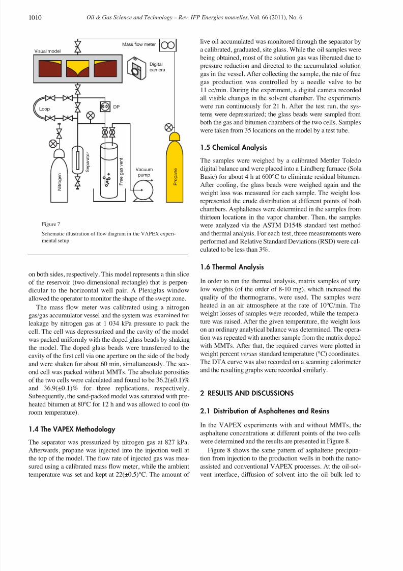
1.3 Apparatus and Setup
The flow diagram of the experimental setup is schematically
illustrated in Figure 7. The VAPEX cell was a three-dimen-
sional rectangular visual model as a symbol of a reservoir
cross-section with 673 × 153 × 31 mm dimensions and 3 300
cc volume, containing 5, 3 and 2 ports at the bottom, top and
Figure 5
Schematic presentation of spiking the MMT nanoclays into
the glass beads media.
Figure 6
The SEM image of doped glass beads with MMT particles
(before sieving).
Rotary mixer
Glass-beads
Rubber Roller
Condensate
spray
Nozzle
1009K. Pourabdollah et al. / Improvement of Heavy Oil Recovery in the VAPEX Process using Montmorillonite Nanoclays
8/12/2019 Improvement of Heavy Oil Recovery in the VAPEX Process Using Montmorillonite Nanoclays
http://slidepdf.com/reader/full/improvement-of-heavy-oil-recovery-in-the-vapex-process-using-montmorillonite 6/12
Oil & Gas Science and Technology – Rev. IFP Energies nouvelles, Vol. 66 (2011), No. 61010
on both sides, respectively. This model represents a thin slice
of the reservoir (two-dimensional rectangle) that is perpen-
dicular to the horizontal well pair. A Plexiglas window
allowed the operator to monitor the shape of the swept zone.The mass flow meter was calibrated using a nitrogen
gas/gas accumulator vessel and the system was examined for
leakage by nitrogen gas at 1 034 kPa pressure to pack the
cell. The cell was depressurized and the cavity of the model
was packed uniformly with the doped glass beads by shaking
the model. The doped glass beads were transferred to the
cavity of the first cell via one aperture on the side of the body
and were shaken for about 60 min, simultaneously. The sec-
ond cell was packed without MMTs. The absolute porosities
of the two cells were calculated and found to be 36.2(±0.1)%
and 36.9(±0.1)% for three replications, respectively.
Subsequently, the sand-packed model was saturated with pre-
heated bitumen at 80ºC for 12 h and was allowed to cool (to
room temperature).
1.4 The VAPEX Methodology
The separator was pressurized by nitrogen gas at 827 kPa.
Afterwards, propane was injected into the injection well at
the top of the model. The flow rate of injected gas was mea-
sured using a calibrated mass flow meter, while the ambient
temperature was set and kept at 22(±0.5)°C. The amount of
live oil accumulated was monitored through the separator by
a calibrated, graduated, site glass. While the oil samples were
being obtained, most of the solution gas was liberated due to
pressure reduction and directed to the accumulated solution
gas in the vessel. After collecting the sample, the rate of free
gas production was controlled by a needle valve to be
11 cc/min. During the experiment, a digital camera recorded
all visible changes in the solvent chamber. The experimentswere run continuously for 21 h. After the test run, the sys-
tems were depressurized; the glass beads were sampled from
both the gas and bitumen chambers of the two cells. Samples
were taken from 35 locations on the model by a test tube.
1.5 Chemical Analysis
The samples were weighed by a calibrated Mettler Toledo
digital balance and were placed into a Lindberg furnace (Sola
Basic) for about 4 h at 600°C to eliminate residual bitumen.
After cooling, the glass beads were weighed again and the
weight loss was measured for each sample. The weight loss
represented the crude distribution at different points of bothchambers. Asphaltenes were determined in the samples from
thirteen locations in the vapor chamber. Then, the samples
were analyzed via the ASTM D1548 standard test method
and thermal analysis. For each test, three measurements were
performed and Relative Standard Deviations (RSD) were cal-
culated to be less than 3%.
1.6 Thermal Analysis
In order to run the thermal analysis, matrix samples of very
low weights (of the order of 8-10 mg), which increased the
quality of the thermograms, were used. The samples wereheated in an air atmosphere at the rate of 10ºC/min. The
weight losses of samples were recorded, while the tempera-
ture was raised. After the given temperature, the weight loss
on an ordinary analytical balance was determined. The opera-
tion was repeated with another sample from the matrix doped
with MMTs. After that, the required curves were plotted in
weight percent versus standard temperature (°C) coordinates.
The DTA curve was also recorded on a scanning calorimeter
and the resulting graphs were recorded similarly.
2 RESULTS AND DISCUSSIONS
2.1 Distribution of Asphaltenes and Resins
In the VAPEX experiments with and without MMTs, the
asphaltene concentrations at different points of the two cells
were determined and the results are presented in Figure 8.
Figure 8 shows the same pattern of asphaltene precipita-
tion from injection to the production wells in both the nano-
assisted and conventional VAPEX processes. At the oil-sol-
vent interface, diffusion of solvent into the oil bulk led to
Figure 7
Schematic illustration of flow diagram in the VAPEX experi-
mental setup.
Mass flow meter
Digital
camera
Loop DP
Vacuum
pump S e p a r a t o r
F r e e
g a s
v e n t
P r o p a n e
N i t r o g e n
Visual model

8/12/2019 Improvement of Heavy Oil Recovery in the VAPEX Process Using Montmorillonite Nanoclays
http://slidepdf.com/reader/full/improvement-of-heavy-oil-recovery-in-the-vapex-process-using-montmorillonite 7/12
formation of asphaltene micelles, which tended to be
adsorbed on the surrounding sides (glass beads or solid parti-
cles).
According to Figure 8, two comparative adsorption phe-
nomena are active in the media; adsorption of asphaltene par-
ticles by MMTs and deposition of asphaltenes on the matrix
surfaces, whose contents were calculated by comparing the
remaining asphaltenes in both cells to be in the range of 40-48% of total precipitated asphaltenes, which were the main
portion of precipitated asphaltenes.
As discussed before, the MMT crystal lattice induced a
net surface negative charge (dangling hydroxyl end-groups)
that led to the adsorption of metal, cation and sulfur atoms in
the interlayer spaces and external surfaces. These negative
charges navigate the adsorption of asphaltene as well as the
penetration of resins into the interlayer spaces of the MMT's
structure. Figure 9 shows the pattern of resin distribution in
the swept zone.
In addition, the results showed that the asphaltene content
of the produced oil was markedly lower when MMTs wereused. This revealed that more asphaltenes remained in the
matrix and the quality of the produced oil was enhanced. The
formation damage which is caused by asphaltene deposition
can be removed by washing.
Furthermore, the content of residual asphaltene in the
swept zone (vapor chamber) is more than the bitumen cham-
ber. The asphaltene distribution is not uniform in the swept
zone. Its concentration around the injection well is maxi-
mum, while around the production well and both sides it is
minimum. Around the injection well, the concentration gradi-
ent between solvent and bitumen increases and thereby the
mass transfer is enhanced. Hence, more asphaltene will beprecipitated. Far from this zone, the reduction of solvent con-
centration leads to a decrease in the concentration gradient
and decline in the asphaltene deposition. Therefore, the pre-
cipitated asphaltene decreases markedly around the produc-
tion well.
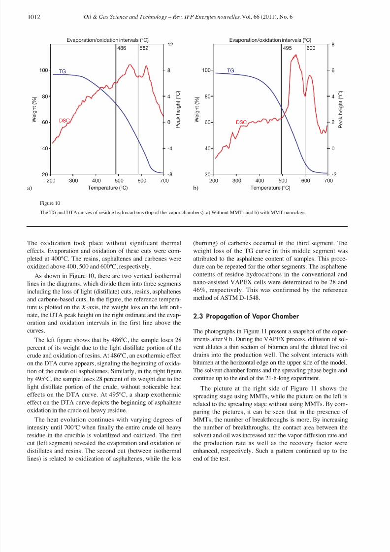
2.2 Interpretation of TG/DTA Curves
Figure 10 shows the combined TG/DTA curves of residue
hydrocarbons coating the glass beads.
As the temperature rose, first the residual light cuts includ-
ing light naphtha, kerosene and gasoil evaporated from thesample. This is between ambient temperatures and 200°C
which is not shown in the figure. Then, higher cuts including
n-paraffins, light oil cuts, paraffin-naphthenes, naphthene-
paraffins and polycyclic aromatic compounds were oxidized
Figure 8
The percent of asphaltene content in residue hydrocarbons at different points of the solvent chamber:
a) the conventional VAPEX cell without MMTs and b) the nano-assisted cell with MMTs.
Vapor injection
Live oil production
22 25 25 28
23 21
28
32.3 32.3
Vapor injection
Live oil production
42 45 48 47 44
40
50
Vapor chamber
Bitumen
22
42
3640
3940
26
26
23
21
25
40
Figure 9
The percent of resin content in residue hydrocarbons at different points of the solvent chamber:
a) the conventional VAPEX cell without MMTs and b) the nano-assisted cell with MMTs.
Vapor injection
Live oil production
10 11 13
1413 12 11
1618
20 21 20 1916
Vapor chamber
Bitumen
Vapor injection
Live oil production
3.23.2
19 20
20
20
19
19
12 13
12
11
9
12
a) b)
a) b)
1011K. Pourabdollah et al. / Improvement of Heavy Oil Recovery in the VAPEX Process using Montmorillonite Nanoclays
8/12/2019 Improvement of Heavy Oil Recovery in the VAPEX Process Using Montmorillonite Nanoclays
http://slidepdf.com/reader/full/improvement-of-heavy-oil-recovery-in-the-vapex-process-using-montmorillonite 8/12
Oil & Gas Science and Technology – Rev. IFP Energies nouvelles, Vol. 66 (2011), No. 61012
The oxidization took place without significant thermal
effects. Evaporation and oxidation of these cuts were com-
pleted at 400°C. The resins, asphaltenes and carbenes were
oxidized above 400, 500 and 600ºC, respectively.
As shown in Figure 10, there are two vertical isothermal
lines in the diagrams, which divide them into three segments
including the loss of light (distillate) cuts, resins, asphaltenesand carbene-based cuts. In the figure, the reference tempera-
ture is plotted on the X -axis, the weight loss on the left ordi-
nate, the DTA peak height on the right ordinate and the evap-
oration and oxidation intervals in the first line above the
curves.
The left figure shows that by 486ºC, the sample loses 28
percent of its weight due to the light distillate portion of the
crude and oxidation of resins. At 486ºC, an exothermic effect
on the DTA curve appears, signaling the beginning of oxida-
tion of the crude oil asphaltenes. Similarly, in the right figure
by 495ºC, the sample loses 28 percent of its weight due to the
light distillate portion of the crude, without noticeable heateffects on the DTA curve. At 495ºC, a sharp exothermic
effect on the DTA curve depicts the beginning of asphaltene
oxidation in the crude oil heavy residue.
The heat evolution continues with varying degrees of
intensity until 700ºC when finally the entire crude oil heavy
residue in the crucible is volatilized and oxidized. The first
cut (left segment) revealed the evaporation and oxidation of
distillates and resins. The second cut (between isothermal
lines) is related to oxidization of asphaltenes, while the loss
(burning) of carbenes occurred in the third segment. The
weight loss of the TG curve in this middle segment was
attributed to the asphaltene content of samples. This proce-
dure can be repeated for the other segments. The asphaltene
contents of residue hydrocarbons in the conventional and
nano-assisted VAPEX cells were determined to be 28 and
46%, respectively. This was confirmed by the referencemethod of ASTM D-1548.
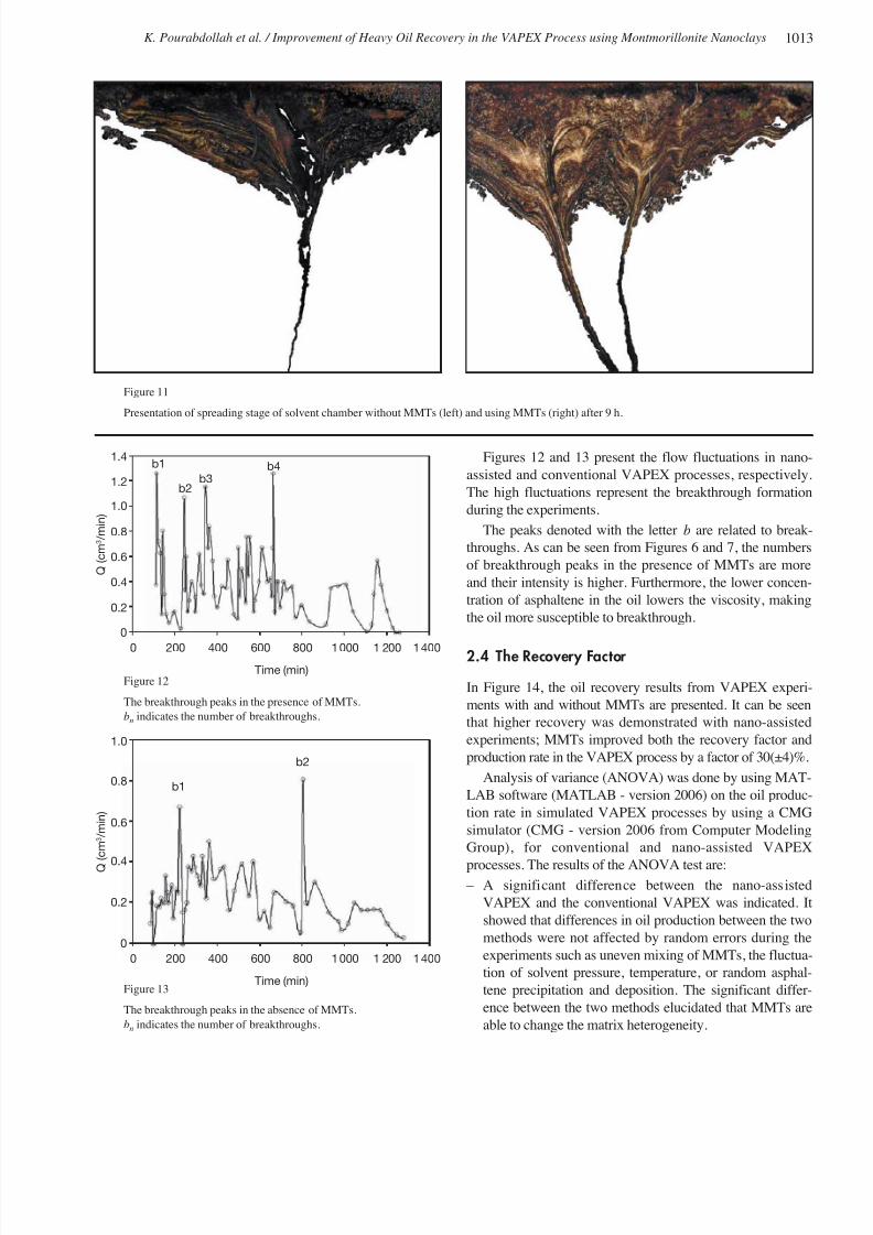
2.3 Propagation of Vapor Chamber
The photographs in Figure 11 present a snapshot of the exper-
iments after 9 h. During the VAPEX process, diffusion of sol-
vent dilutes a thin section of bitumen and the diluted live oil
drains into the production well. The solvent interacts with
bitumen at the horizontal edge on the upper side of the model.
The solvent chamber forms and the spreading phase begin and
continue up to the end of the 21-h-long experiment.
The picture at the right side of Figure 11 shows thespreading stage using MMTs, while the picture on the left is
related to the spreading stage without using MMTs. By com-
paring the pictures, it can be seen that in the presence of
MMTs, the number of breakthroughs is more. By increasing
the number of breakthroughs, the contact area between the
solvent and oil was increased and the vapor diffusion rate and
the production rate as well as the recovery factor were
enhanced, respectively. Such a pattern continued up to the
end of the test.
Figure 10
The TG and DTA curves of residue hydrocarbons (top of the vapor chambers): a) Without MMTs and b) with MMT nanoclays.
100 TG
DSC W e i g h t ( % )
Temperature (°C)
Evaporation/oxidation intervals (°C)
P e a k h e i g h t ( ° C )
12582486
8
4
0
-4
-8
80
60
40
20200 300 400 500 600 700
100 TG
DSC W e i g h t ( % )
Temperature (°C)
Evaporation/oxidation intervals (°C)
P e a k h e i g h t ( ° C )
8600495
6
4
2
0
-2
80
60
40
20200 300 400 500 600 700
a) b)
8/12/2019 Improvement of Heavy Oil Recovery in the VAPEX Process Using Montmorillonite Nanoclays
http://slidepdf.com/reader/full/improvement-of-heavy-oil-recovery-in-the-vapex-process-using-montmorillonite 9/12
Figures 12 and 13 present the flow fluctuations in nano-
assisted and conventional VAPEX processes, respectively
The high fluctuations represent the breakthrough formation
during the experiments.
The peaks denoted with the letter b are related to break-
throughs. As can be seen from Figures 6 and 7, the numbers
of breakthrough peaks in the presence of MMTs are more
and their intensity is higher. Furthermore, the lower concen-
tration of asphaltene in the oil lowers the viscosity, making
the oil more susceptible to breakthrough.
2.4 The Recovery Factor
In Figure 14, the oil recovery results from VAPEX experi-
ments with and without MMTs are presented. It can be seen
that higher recovery was demonstrated with nano-assisted
experiments; MMTs improved both the recovery factor and
production rate in the VAPEX process by a factor of 30(±4)%.
Analysis of variance (ANOVA) was done by using MAT-
LAB software (MATLAB - version 2006) on the oil produc-
tion rate in simulated VAPEX processes by using a CMG
simulator (CMG - version 2006 from Computer Modeling
Group), for conventional and nano-assisted VAPEX
processes. The results of the ANOVA test are: – A significant difference between the nano-assisted
VAPEX and the conventional VAPEX was indicated. It
showed that differences in oil production between the two
methods were not affected by random errors during the
experiments such as uneven mixing of MMTs, the fluctua-
tion of solvent pressure, temperature, or random asphal-
tene precipitation and deposition. The significant differ-
ence between the two methods elucidated that MMTs are
able to change the matrix heterogeneity.
Figure 11
Presentation of spreading stage of solvent chamber without MMTs (left) and using MMTs (right) after 9 h.
Figure 12
The breakthrough peaks in the presence of MMTs.
bnindicates the number of breakthroughs.
Figure 13
The breakthrough peaks in the absence of MMTs.
bn
indicates the number of breakthroughs.
Time (min)
Q
( c m 3 / m i n )
1.4
1.2
1.0
0.8
0.6
0.4
0.2
0
0 200 400 600 800 1000 1 200 1400
b1
b2b3
b4
Time (min)
Q
( c m 3 / m i n )
1.0
0.8 b1
b2
0.6
0.4
0.2
0
0 200 400 600 800 1000 1 200 1400
1013K. Pourabdollah et al. / Improvement of Heavy Oil Recovery in the VAPEX Process using Montmorillonite Nanoclays

8/12/2019 Improvement of Heavy Oil Recovery in the VAPEX Process Using Montmorillonite Nanoclays
http://slidepdf.com/reader/full/improvement-of-heavy-oil-recovery-in-the-vapex-process-using-montmorillonite 10/12
Oil & Gas Science and Technology – Rev. IFP Energies nouvelles, Vol. 66 (2011), No. 61014
– There was no difference between the simulated VAPEX
and the conventional VAPEX. This confirmed the accu-
racy of the simulated model and revealed that the simu-
lated VAPEX and conventional VAPEX processes were
matched.
In addition, according to Darcy's equation (Eq. 1), the pro-
duction rate is dependent on the interfacial surface area, the
viscosity, etc.
(1)
where Q denotes the flow rate of the produced oil, A presents
the interfacial surface area, and k and μ are the matrix perme-
ability and the fluid viscosity, respectively. The term ΔP/L
shows the pressure gradient along with the length of the
matrix.
In the nano-assisted VAPEX model, not only did the inter-
facial area increase (for the sake of breakthrough), but the
heavy oil viscosity also decreased (for the sake of asphaltene
transfer from the oil media into the interlayer spaces of
MMTs).
The viscosity of the produced live oil was measured
experimentally using an online high-pressure capillary vis-
cometer, which is represented in Figure 7. Figure 15 depictsthe viscosity of the produced oil versus the run time. As can
be observed from this figure and according to the reasons
mentioned above, the MMT nanoclays markedly reduced the
oil viscosity.
Therefore, the production rate increased. Moreover, the
specific gravity of MMTs is more than heavy oil. After
adsorption of asphaltene into the MMTs (intercalation), this
difference was even more, and this led to improving the live
oil gravity drainage via convectional mass transfer. This led
to enhancing the production rate and the recovery factor.
2.5 Solvent Consumption
Breakthrough is a dynamic phenomenon that forms in two-
phase systems. The solvent chamber/bitumen system in the
VAPEX process is prone to breakthrough formation.
During this phenomenon, a part of the injected vapor was
lost through the separator without dilution of bitumen.
Therefore, the in situ solvent was considered to be distrib-
uted in two media; one, which had diffused into the heavy
oil, and the other, which was trapped in the pore volumes
of the swept zone. The ratio of dissolution efficiency was
defined as the rate of dissolved solvent to the rate of
injected solvent. The experimental results revealed that theratio of the dissolved solvent to the injected solvent in the
nano-assisted VAPEX method is more than the conven-
tional VAPEX method. Figure 16 shows the comparative
diagram of dissolution efficiency for nano-assisted and
conventional VAPEX processes.
The MMT's form enhanced breakthrough with a high
aspect ratio to increase the vapor diffusion and the bitumen
dilution.
Adsorption of asphaltene particles in the MMT's structure
led to reducing the asphaltene deposition on the matrix sur-
faces. The wettability of the matrix did not shift to oil-wetconditions and the permeability remained constant.
Moreover, intercalation of asphaltenes into the MMTs
reduced the oil viscosity, enhanced the gravity drainage,
increased the falling rate of live oil, and expanded the interfa-
cial area between the original oil and the vapor chamber.
According to the hypothesis of surface renewal, the concen-
tration gradient between the solvent and the heavy oil was
increased. This led to increasing the solvent diffusion into the
heavy oil as well as the effective consumption of the solvent.
0
5
10
15
20
25
30
35
0 5 10 15 20 25
Time (h)
R e c o v e r y f a c t o r ( % )
Without nanoclay
With nanoclay
Figure 15
The measured viscosity of produced oil versus the run time in
conventional and nano-assisted experiments.
Figure 14
Recovery factor in the presence and absent of MMTs in the
VAPEX process.
0
0.5
1.0
1.5
2.0
Time (min)
L o g v i s c
o s i t y ( c p )
Without nanoclay With nanoclay
0 200 400 600 800 1000 1 200 1400

8/12/2019 Improvement of Heavy Oil Recovery in the VAPEX Process Using Montmorillonite Nanoclays
http://slidepdf.com/reader/full/improvement-of-heavy-oil-recovery-in-the-vapex-process-using-montmorillonite 11/12
3 RECOMMENDATIONS FOR INJECTING THE MMT
NANOCLAYS
There are some restrictions in selecting the carrier to move
the MMT particles from the wellhead to the bottom hole; in
the case of MMTs, water is not a suitable carrier, because of
the clay swelling. Reduction of carrier viscosity leads to
more penetration of the carrier and nanoparticles into the
reservoir media and the greater efficiency of the process.
Nowadays, some technical methods, such as Coiled Tubing
(CT) and a bullhead (BH), are used for acid and hydraulic oilinjection into the reservoirs. Injection of nanoparticles into
the reservoir can be done via both the solvent injection wells
and the live oil production wells by CT or BH methods.
CONCLUSIONS
Quantitative and qualitative analysis of remaining heavy oil
asphaltenes and resins in the VAPEX matrix was carried out
by TG and DTA methods, respectively. The high content of
precipitated asphaltenes and resins in the nano-assisted
matrix revealed that asphaltenes and resins were markedly
adsorbed into the MMT's interlayer spaces. Distributions of asphaltenes and resins were not uniform in the swept zone
and their concentration around the injection well was maxi-
mum, while around the production well and both sides it was
minimum. Moreover, the ANOVA test showed a significant
difference between the nano-assisted VAPEX and the con-
ventional VAPEX. The difference in the oil production rate
between the two methods was not affected by random errors
during the experiments. It elucidated that MMTs were able to
change the matrix heterogeneity. The greater oil recovery and
more effective consumption of solvent (30±4%) using
MMTs were directly related to the greater contact areas
formed by formation of more breakthroughs, adsorption of
asphaltenes into the MMT's interlayer spaces and reduction
of oil viscosity.
ACKNOWLEDGEMENTS
The assistance of Mr. Salimi, the PUT technician, as well as
Miss Mahdavi in carrying out the experiments is appreciated
The authors also thank Dr. Nasr Esfahany (Isfahan
University of Technology), Prof. Rashidi (Amirkabir
University of Technology) and Dr. Torabi (The University of
Tehran) for their valuable comments in preparing this paper
Furthermore, the financial supports of Islamic Azad
University (Shahreza Branch) and Iran Nanotechnology
Initiative Council are gratefully acknowledged.
REFERENCES
1 Pourabdollah K., Zarringhalam Moghaddam A., Kharrat R.Mokhtari B. (2010) Study of Asphaltene and Metal Upgradingin VAPEX Process, Energ. Fuel. 24, 8, 4396-4401.
2 Altunina L.K., Kuvshinov V.A. (2008) Improved OiRecovery of High-Viscosity Oil Pools with PhysicochemicalMethods and Thermal-Steam Treatments, Oil Gas SciTechnol. 63, 1, 37-48.
3 Golovko Y., Gorbunova L., Kamyanov V., Pevneva G.Filimonova T. (2008) Principal Regularities in Compositionsand Structures of High-Molecular Compounds from Crude Oilsand Natural Bitumens, Oil Gas Sci. Technol. 63, 1, 95-114.
4 Hénaut I., Argillier J.F. (2004) Pipeline Transportation ofHeavy Oils, a Strategic, Economic and TechnologicalChallenge, Oil Gas Sci. Technol. 59, 5, 455-466.
5 Shu W.R. (1984) A viscosity correlation for mixtures ofheavy oil, bitumen, and petroleum fractions, Soc. Pet. Eng. J24, 3, 277-282.
6 Karoussi O.L., Skovbjerg L., Hassenkam T., Svane-StippS.L., Hamouda A.A. (2008) AFM Study of Calcite SurfaceExposed to Stearic and Heptanoic Acids, Colloid. Surface. A325, 107-122.
7 Kasevich R.S. (2008) Method and apparatus for in-situradiofrequency assisted gravity drainage of oil (RAGD), USPatent 7441597.
8 Abu-Khader M.M., Speight J.G. (2007) Influence of highasphaltene Feedstock on processing, Oil Gas Sci. Technol. 62715-722.
9 Mousavi-Dehghani S.A., Vafaie-Sefti M., Mirzayi B.
Fasih M. (2007) Experimental Investigation on AsphalteneDeposition, in Porous Media during Miscible Gas Injection Iran. J. Chem. Chem. Eng. 26, 4, 39-48.
10 Das S.K., Butler R.M. (1994) Vapor Extraction of Heavy Oiand Bitumen: A Review, J. Can. Petrol. Technol. 33, 39-45.
11 Kök M.V., Yildirim Y., Akin S. (2009) Application of VaporExtraction (VAPEX) Process on Carbonate Reservoirs, EnergySources, Part A . 31, 377-386.
12 Johnson J.R., Koros W.J. (2009) Utilization of nanoplateletsin organic–inorganic hybrid separation materials: Separationadvantages and formation challenges, Taiwan Institute Chem Eng. J. 40, 268-275.
Figure 16
Dissolution efficiency in the presence and absent of MMTs in
the VAPEX process.
0 5 10 15 20 25
0
2
4
6
8
Time (h)
D i s s o l u t i o
n e f f i c i e n c y ( % )
Without nanoclay
With nanoclay
1015K. Pourabdollah et al. / Improvement of Heavy Oil Recovery in the VAPEX Process using Montmorillonite Nanoclays

8/12/2019 Improvement of Heavy Oil Recovery in the VAPEX Process Using Montmorillonite Nanoclays
http://slidepdf.com/reader/full/improvement-of-heavy-oil-recovery-in-the-vapex-process-using-montmorillonite 12/12
Oil & Gas Science and Technology – Rev. IFP Energies nouvelles, Vol. 66 (2011), No. 61016
13 Joshi G.V., Kevadiya B.D., Patel H.A., Bajaj H.C., Jasra R.V.(2009) Montmorillonite as a Drug Delivedry System:Intercalation and in Vitro Release of Timolol Maleate,Pharmaceutics 374, 53-57.
14 Masih D., Izumi Y., Aika K., Seida Y. (2007) Optimization of an Iron Intercalated Montmorillonite Preparation for theRemoval of Arsenic at Low Concentrations, Eng. L ife Sci. 7,52-60.
15 Stathi P., Papadas I.T., Enotiadis A.R., Gengler Y.N.,
Gournis D., Rudolf P., Deligiannakis Y. (2009) Effects of Acetate on Cation Exchange Capacity of a Zn-ContainingMontmorillonite. Physicochemical Significance and MetalUptake, Langmuir 25, 6825-6833.
16 Navratilova Z., Wojtowicz P., Vaculikova L., Sugarkova V.(2007) Sorption of Alkylammonium Cations onMontmorillonite, Acta Geodyn. Geomater. 4, 59-65.
17 Fusova L. (2009) Modification of the Structure of Ca-Montmorillonite Modifikace Struktury Ca-Montmorillonitu,Geo. Sci. Eng. LV, 27-32.
18 Patel H.A., Somani R.S., Bajaj H.C., Jasra R.V. (2006)Nanoclays for Polymer Nanocomposites, Paints, Inks, Greasesand Cosmetics Formulations, Drug Delivery Vehicle andWaste Water Treatment, B. Mater. Sci. 29, 133-145.
19 Lin J.J., Wei J.C., Juang T.Y., Tsai W.C. (2007) Preparationof Protein-Silicate Hybrids from Polyamine Intercalation of Layered Montmorillonite, Langmuir 23, 1995-1999.
20 Rahman Z.A., Hamzah U., Ahmad N. (2010) Geotechnicalcharacteristics of oil-contaminated granitic and metasedimen-tary soils, Asian J. Appl. Sci. 3, 237-249.
21 Pourabdollah K. (2010) Modeling and Optimization of VAPEX Process in Fractured Reservoirs, PhD Thesis, TarbiatModares University, Tehran, Iran.
22 Shishkin Y.L. (2006) Scanning Calorimetry andThermogravimetry in Analysis of Petroleum Systems.Determination of the Component Composition, Chem.Technol. Fuels Oils 42, 4, 300-307.
23 Ali M.A., Siddiqui M.A.B., Zaidi S.M.J. (1998) ThermalAnalysis of Crude Oils and Comparison with SIMDIST and
TBP Distillation Data, Therm. Anal. 51, 307-319.
24 Kök M.V. (1999) Feasibility study of crude oil fields by ther-mal analysis technique, J. Therm. Anal. Calorim. 56, 947-951.
25 Kök M.V., Karacan O., Pamir R. (1998) Kinetic Analysis of Oxidation Behavior of Crude Oil SARA Constituents, Energ.Fuel. 12, 3, 580-588.
26 Karacan O., Kök M.V. (1997) Pyrolysis Analysis of CrudeOils and Their Fractions, Energ. Fuel. 11, 2, 385-391.
27 Kök M.V., Okandan E. (1994) Thermal analysis of crude oil-lignite mixtures by differential scanning calorimetry, Fuel 73,4, 500-504.
Final manuscript received in January 2011
Published online in October 2011
Copyright © 2011 IFP Energies nouvelles
Permission to make digital or hard copies of part or all of this work for personal or classroom use is granted without fee provided that copies are not made
or distributed for profit or commercial advantage and that copies bear this notice and the full citation on the first page. Copyrights for components of thiswork owned by others than IFP Energies nouvelles must be honored. Abstracting with credit is permitted. To copy otherwise, to republish, to post onservers, or to redistribute to lists, requires prior specific permission and/or a fee: Request permission from Information Mission, IFP Energies nouvelles, fax. +33 1 47 52 70 96, or [email protected].