Embed Size (px)
Citation preview

Improvement in Fast Particle Track Reconstruction1
with Robust Statistics2
M. G. Aartsen2, R. Abbasi27, Y. Abdou22, M. Ackermann42, J. Adams15,3
J. A. Aguilar21, M. Ahlers27, D. Altmann9, J. Auffenberg27, X. Bai31,1,4
M. Baker27, S. W. Barwick23, V. Baum28, R. Bay43, J. J. Beatty17,18,5
S. Bechet12, J. Becker Tjus10, K.-H. Becker41, M. L. Benabderrahmane42,6
S. BenZvi27, P. Berghaus42, D. Berley16, E. Bernardini42, A. Bernhard30,7
D. Z. Besson25, G. Binder8,43, D. Bindig41, M. Bissok1, E. Blaufuss16,8
J. Blumenthal1, D. J. Boersma40, S. Bohaichuk20, C. Bohm34, D. Bose13,9
S. Boser11, O. Botner40, L. Brayeur13, H.-P. Bretz42, A. M. Brown15,10
R. Bruijn24, J. Brunner42, M. Carson22, J. Casey5, M. Casier13, D. Chirkin27,11
A. Christov21, B. Christy16, K. Clark39, F. Clevermann19, S. Coenders1,12
S. Cohen24, D. F. Cowen39,38, A. H. Cruz Silva42, M. Danninger34,13
J. Daughhetee5, J. C. Davis17, M. Day27, C. De Clercq13, S. De Ridder22,14
P. Desiati27, K. D. de Vries13, M. de With9, T. DeYoung39, J. C. Dıaz-Velez27,15
M. Dunkman39, R. Eagan39, B. Eberhardt28, J. Eisch27, S. Euler1,16
P. A. Evenson31, O. Fadiran27, A. R. Fazely6, A. Fedynitch10, J. Feintzeig27,17
T. Feusels22, K. Filimonov43, C. Finley34, T. Fischer-Wasels41, S. Flis34,18
A. Franckowiak11, K. Frantzen19, T. Fuchs19, T. K. Gaisser31, J. Gallagher26,19
L. Gerhardt8,43, L. Gladstone27, T. Glusenkamp42, A. Goldschmidt8,20
G. Golup13, J. G. Gonzalez31, J. A. Goodman16, D. Gora42,21
D. T. Grandmont20, D. Grant20, A. Groß30, C. Ha8,43, A. Haj Ismail22,22
P. Hallen1, A. Hallgren40, F. Halzen27, K. Hanson12, D. Heereman12,23
D. Heinen1, K. Helbing41, R. Hellauer16, S. Hickford15, G. C. Hill2,24
K. D. Hoffman16, R. Hoffmann41, A. Homeier11, K. Hoshina27,25
W. Huelsnitz16,2, P. O. Hulth34, K. Hultqvist34, S. Hussain31, A. Ishihara14,26
E. Jacobi42, J. Jacobsen27, K. Jagielski1, G. S. Japaridze4, K. Jero27,27
O. Jlelati22, B. Kaminsky42, A. Kappes9, T. Karg42, A. Karle27, J. L. Kelley27,28
J. Kiryluk35, J. Klas41, S. R. Klein8,43, J.-H. Kohne19, G. Kohnen29,29
H. Kolanoski9, L. Kopke28, C. Kopper27, S. Kopper41, D. J. Koskinen39,30
M. Kowalski11, M. Krasberg27, K. Krings1, G. Kroll28, J. Kunnen13,31
N. Kurahashi27, T. Kuwabara31, M. Labare22, H. Landsman27, M. J. Larson37,32
M. Lesiak-Bzdak35, M. Leuermann1, J. Leute30, J. Lunemann28, O. Macıas15,33
J. Madsen33, G. Maggi13, R. Maruyama27, K. Mase14, H. S. Matis8,34
F. McNally27, K. Meagher16, M. Merck27, T. Meures12, S. Miarecki8,43,35
E. Middell42, N. Milke19, J. Miller13, L. Mohrmann42, T. Montaruli21,3,36
∗Corresponding author. Email: [email protected], Phone: 304-542-4464, Address:Wisconsin Institutes for Discovery, 330 N. Orchard St., Madison, WI 53715
1Physics Department, South Dakota School of Mines and Technology, Rapid City, SD57701, USA
2Los Alamos National Laboratory, Los Alamos, NM 87545, USA3also Sezione INFN, Dipartimento di Fisica, I-70126, Bari, Italy4NASA Goddard Space Flight Center, Greenbelt, MD 20771, USA
Preprint submitted to Nuclear Instruments & Methods A October 20, 2013

R. Morse27, R. Nahnhauer42, U. Naumann41, H. Niederhausen35,37
S. C. Nowicki20, D. R. Nygren8, A. Obertacke41, S. Odrowski20, A. Olivas16,38
A. Omairat41, A. O’Murchadha12, L. Paul1, J. A. Pepper37,39
C. Perez de los Heros40, C. Pfendner17, D. Pieloth19, E. Pinat12, J. Posselt41,40
P. B. Price43, G. T. Przybylski8, L. Radel1, M. Rameez21, K. Rawlins3,41
P. Redl16, R. Reimann1, E. Resconi30, W. Rhode19, M. Ribordy24,42
M. Richman16, B. Riedel27, J. P. Rodrigues27, C. Rott36, T. Ruhe19,43
B. Ruzybayev31, D. Ryckbosch22, S. M. Saba10, T. Salameh39, H.-G. Sander28,44
M. Santander27, S. Sarkar32, K. Schatto28, F. Scheriau19, T. Schmidt16,45
M. Schmitz19, S. Schoenen1, S. Schoneberg10, A. Schonwald42, A. Schukraft1,46
L. Schulte11, O. Schulz30, D. Seckel31, Y. Sestayo30, S. Seunarine33,47
R. Shanidze42, C. Sheremata20, M. W. E. Smith39, D. Soldin41,48
G. M. Spiczak33, C. Spiering42, M. Stamatikos17,4, T. Stanev31, A. Stasik11,49
T. Stezelberger8, R. G. Stokstad8, A. Stoßl42, E. A. Strahler13, R. Strom40,50
G. W. Sullivan16, H. Taavola40, I. Taboada5, A. Tamburro31, A. Tepe41,51
S. Ter-Antonyan6, G. Tesic39, S. Tilav31, P. A. Toale37, S. Toscano27,52
E. Unger10, M. Usner11, S. Vallecorsa21, N. van Eijndhoven13,53
A. Van Overloop22, J. van Santen27, M. Vehring1, M. Voge11, M. Vraeghe22,54
C. Walck34, T. Waldenmaier9, M. Wallraff1, Ch. Weaver27, M. Wellons27,55
C. Wendt27, S. Westerhoff27, N. Whitehorn27, K. Wiebe28, C. H. Wiebusch1,56
D. R. Williams37, H. Wissing16, M. Wolf34, T. R. Wood20, K. Woschnagg43,57
D. L. Xu37, X. W. Xu6, J. P. Yanez42, G. Yodh23, S. Yoshida14,58
P. Zarzhitsky37, J. Ziemann19, S. Zierke1, M. Zoll34,59
and B. Recht43, C. Re4460
1III. Physikalisches Institut, RWTH Aachen University, D-52056 Aachen, Germany61
2School of Chemistry & Physics, University of Adelaide, Adelaide SA, 5005 Australia62
3Dept. of Physics and Astronomy, University of Alaska Anchorage, 3211 Providence Dr.,63
Anchorage, AK 99508, USA64
4CTSPS, Clark-Atlanta University, Atlanta, GA 30314, USA65
5School of Physics and Center for Relativistic Astrophysics, Georgia Institute of66
Technology, Atlanta, GA 30332, USA67
6Dept. of Physics, Southern University, Baton Rouge, LA 70813, USA68
7Dept. of Physics, University of California, Berkeley, CA 94720, USA69
8Lawrence Berkeley National Laboratory, Berkeley, CA 94720, USA70
9Institut fur Physik, Humboldt-Universitat zu Berlin, D-12489 Berlin, Germany71
10Fakultat fur Physik & Astronomie, Ruhr-Universitat Bochum, D-44780 Bochum,72
Germany73
11Physikalisches Institut, Universitat Bonn, Nussallee 12, D-53115 Bonn, Germany74
12Universite Libre de Bruxelles, Science Faculty CP230, B-1050 Brussels, Belgium75
13Vrije Universiteit Brussel, Dienst ELEM, B-1050 Brussels, Belgium76
14Dept. of Physics, Chiba University, Chiba 263-8522, Japan77
15Dept. of Physics and Astronomy, University of Canterbury, Private Bag 4800,78
Christchurch, New Zealand79
16Dept. of Physics, University of Maryland, College Park, MD 20742, USA80
17Dept. of Physics and Center for Cosmology and Astro-Particle Physics, Ohio State81
University, Columbus, OH 43210, USA82
18Dept. of Astronomy, Ohio State University, Columbus, OH 43210, USA83
19Dept. of Physics, TU Dortmund University, D-44221 Dortmund, Germany84
20Dept. of Physics, University of Alberta, Edmonton, Alberta, Canada T6G 2E185
2

21Departement de physique nucleaire et corpusculaire, Universite de Geneve, CH-121186
Geneve, Switzerland87
22Dept. of Physics and Astronomy, University of Gent, B-9000 Gent, Belgium88
23Dept. of Physics and Astronomy, University of California, Irvine, CA 92697, USA89
24Laboratory for High Energy Physics, Ecole Polytechnique Federale, CH-1015 Lausanne,90
Switzerland91
25Dept. of Physics and Astronomy, University of Kansas, Lawrence, KS 66045, USA92
26Dept. of Astronomy, University of Wisconsin, Madison, WI 53706, USA93
27Dept. of Physics and Wisconsin IceCube Particle Astrophysics Center, University of94
Wisconsin, Madison, WI 53706, USA95
28Institute of Physics, University of Mainz, Staudinger Weg 7, D-55099 Mainz, Germany96
29Universite de Mons, 7000 Mons, Belgium97
30T.U. Munich, D-85748 Garching, Germany98
31Bartol Research Institute and Department of Physics and Astronomy, University of99
Delaware, Newark, DE 19716, USA100
32Dept. of Physics, University of Oxford, 1 Keble Road, Oxford OX1 3NP, UK101
33Dept. of Physics, University of Wisconsin, River Falls, WI 54022, USA102
34Oskar Klein Centre and Dept. of Physics, Stockholm University, SE-10691 Stockholm,103
Sweden104
35Department of Physics and Astronomy, Stony Brook University, Stony Brook, NY105
11794-3800, USA106
36Department of Physics, Sungkyunkwan University, Suwon 440-746, Korea107
37Dept. of Physics and Astronomy, University of Alabama, Tuscaloosa, AL 35487, USA108
38Dept. of Astronomy and Astrophysics, Pennsylvania State University, University Park,109
PA 16802, USA110
39Dept. of Physics, Pennsylvania State University, University Park, PA 16802, USA111
40Dept. of Physics and Astronomy, Uppsala University, Box 516, S-75120 Uppsala, Sweden112
41Dept. of Physics, University of Wuppertal, D-42119 Wuppertal, Germany113
42DESY, D-15735 Zeuthen, Germany114
43Dept. of Computer Science, University of California, Berkeley, CA 94704, USA115
44Dept. of Computer Science, Stanford University, Stanford, CA 94305, USA116
Abstract117
The IceCube project has transformed one cubic kilometer of deep natural118
Antarctic ice into a Cherenkov detector. Muon neutrinos are detected and their119
direction inferred by mapping the light produced by the secondary muon track120
inside the volume instrumented with photomultipliers. Reconstructing the muon121
track from the observed light is challenging due to noise, light scattering in the122
ice medium, and the possibility of simultaneously having multiple muons inside123
the detector, resulting from the large flux of cosmic ray muons.124
This manuscript describes work on two problems: (1) the track reconstruc-125
tion problem, in which, given a set of observations, the goal is to recover the126
track of a muon; and (2) the coincident event problem, which is to determine127
how many muons are active in the detector during a time window. Rather than128
solving these problems by developing more complex physical models that are129
applied at later stages of the analysis, our approach is to augment the detector’s130
early reconstruction with data filters and robust statistical techniques. These131
can be implemented at the level of on-line reconstruction and, therefore, improve132
all subsequent reconstructions. Using the metric of median angular resolution, a133
3

H. KOLANOSKI ICETOP OVERVIEW
Figure 1: The IceCube Observatory with its componentsDeepCore and IceTop.
of 1 km3 at a depth between 1450 m and 2450 m (Fig. 1). Inthe lower part of the detector a section called DeepCore ismore densely instrumented. The main purpose of IceCubeis the detection of high energy neutrinos from astrophysicalsources via the Cherenkov light of charged particles gener-ated in neutrino interactions in the ice or the rock below theice.
IceTop: The IceTop air shower array is located aboveIceCube at a height of 2832 m above sea level, correspond-ing to an atmospheric depth of about 680 g/cm2. It consistsof 162 ice Cherenkov tanks, placed at 81 stations and dis-tributed over an area of 1 km2 on a grid with mean spacingof 125 m (Fig. 1). In the center of the array, three stationshave been installed at intermediate positions. Togetherwith the neighbouring stations they form an in-fill array fordenser shower sampling. Each station comprises two cylin-drical tanks, 10 m apart from each other, with a diameter of1.86 m and filled with 90 cm ice. The tanks are embed-ded into the snow so that their top surface is level with thesurrounding snow to minimize temperature variations andsnow accumulation caused by wind drift. However, snowaccumulation (mainly due to irregular snow surfaces) can-not be completely avoided so that the snow height has tobe monitored (see ref. [1]) and taken into account in simu-lation and reconstruction (currently this is still a source ofnon-negligible systematic uncertainties).Each tank is equipped with two ‘Digital Optical Mod-ules’ (DOMs), each containing a 10�� photo multiplier tube(PMT) to record the Cherenkov light of charged particlesthat penetrate the tank. In addition, a DOM houses complexelectronic circuitry supplying signal digitisation, readout,triggering, calibration, data transfer and various controlfunctions. The most important feature of the DOM elec-tronics is the recording of the analog waveforms in 3.3 ns
Perp. distance to shower axis [m]100 200 300 400 500 600
Sign
al [V
EM]
-110
1
10
210
310 2.11± = 57.21 125S 0.05 PRELIMINARY ± = 2.93 β
High GainLow Gain
Figure 2: Reconstruction of shower parameters from thelateral distribution.
wide bins for a duration of 422 ns. DOMs, electronics andreadout scheme are the same as for the in-ice detector.The two DOMs in each tank are operated at different PMTgains (1 ·105 and 5 ·106) to cover a dynamic range of morethan 104. The measured charges are expressed in units of‘vertical equivalent muons’ (VEM) determined by calibrat-ing each DOM with muons (see ref. [1]).To initiate the readout of DOMs, a local coincidence ofthe two high gain DOMs of a station is required. This re-sults in a station trigger rate of about 30 Hz compared toabout 1600 Hz of a single high gain DOM at a thresholdof about 0.1 VEM. The data are written to a permanentstorage medium, and are thus available for analysis, if thereadouts of six or more DOMs are launched by a local coin-cidence. This leads to a trigger threshold of about 300 TeV.Additionally, IceTop is always read out in case of a triggerissued by another detector component (and vice versa). Foreach single tank above threshold, even without a local co-incidence, condensed data containing integrated charge andtime stamp are transmitted. These so-called SLC hits (SLC= ‘soft local coincidence’) are useful for detecting singlemuons in showers where the electromagnetic componenthas been absorbed (low energies, outer region of showers,inclined showers).For monitoring transient events via rate variations, the timeof single hits in different tanks with various thresholds arehistogrammed.
3 Shower reconstruction
For each triggered tank in an event, time and charge ofthe signal are evaluated for further processing. Likelihoodmaximisation methods are used to reconstruct location, di-rection and size of the recorded showers. In general, signaltimes contain the direction information, and the charge dis-tribution is connected to shower size and core location. Thestandard analysis requires five or more triggered stationsleading to a reconstruction threshold of about 500 TeV. Aconstant efficiency is reached at about 1 PeV, dependingon shower inclination. For small showers an effort waslaunched to decrease the threshold to about 100 TeV witha modified reconstruction requiring only three stations.
Figure 1: The IceCube neutrino detector in the Antarctic ice. A picture of the Eiffel Toweris shown for scale.
standard metric for track reconstruction, we improve the accuracy in the initial134
reconstruction direction by 13%. We also present improvements in measuring135
the number of muons in coincident events: we can accurately determine the136
number of muons 98% of the time.137
Keywords: IceCube, Track reconstruction, Neutrino telescope, Neutrino138
astrophysics, Robust Statistics139
1. Introduction140
The IceCube neutrino detector searches for neutrinos that are generated by141
the universe’s most violent astrophysical events: exploding stars, gamma ray142
bursts, and cataclysmic phenomena involving black holes and neutron stars [1].143
The detector, roughly one cubic kilometer in size, is located near the geographic144
South Pole and is buried to a depth of about 2.5 km in the Antarctic ice [2].145
The detector is illustrated in Figure 1, and a more complete description is given146
in Section 2.147
When a neutrino enters the telescope, it occasionally interacts in the ice and148
generates a muon. The neutrino direction can be inferred from a reconstruc-149
tion of the muon track. Muons are also generated by cosmic rays interacting150
in the atmosphere, and separation of the background of cosmic ray muons and151
neutrino-induced muons is a necessary step for neutrino analysis. This separa-152
tion is challenging, as the number of observed cosmic ray muons exceeds the153
number of observed neutrino muons by over five orders of magnitude [3].154
4

The primary mechanism for separating the cosmic ray muons from the neu-155
trino muons is reconstructing the muon track and determining whether the muon156
was traveling downwards into the Earth or upwards out of the Earth. Because157
neutrinos can penetrate through the Earth but cosmic ray muons cannot, it158
follows that a muon traveling out of the Earth must have been generated by a159
neutrino. Thus, by selecting only the muons that are reconstructed as up-going,160
the cosmic ray muons can, in principle, be removed from the data. Because the161
number of cosmic ray muons overwhelms the number of neutrino muons, high162
accuracy is critical for preventing erroneous reconstruction of cosmic ray muons163
as neutrino-induced.164
Here, we examine two problems that arise in the separation of cosmic ray165
muons from neutrino muons in the IceCube detector:166
1. Reconstruction, in which the track of a muon is reconstructed from the167
observed light at different positions and times in the detector.168
2. Coincident Event Detection, in which we detect the number of muons169
inside the detector, and assign observed photons to a muon.170
Sophisticated reconstruction techniques have been developed that computa-171
tionally model in detail the muon’s Cherenkov cone, as well as the scattering172
and absorption of photons through layers of Antarctic ice with varying optical173
properties [3–5]. Rather than further refining these techniques, the current work174
focusses on improving the statistical techniques and optimizing data filtering in175
the early online track reconstruction performed on the data in real time at the176
South Pole. Besides benefiting directly any analysis that uses the online recon-177
struction, such as the search for cosmogenic neutrinos, any later analysis will178
benefit from improvements made at the early stages of the data collection.179
1.1. Related Work180
Track reconstruction and coincident event detection challenges are ubiqui-181
tous in particle physics [6–8], both in particle accelerators and cosmic particle182
detectors. While the work described in this manuscript builds on the previous183
technique developed for the IceCube detector [3], these techniques are general184
purpose and potentially have applications in detectors beyond IceCube.185
1.2. Outline186
We begin by describing the IceCube detector and track reconstruction chal-187
lenges in Section 2. In Section 3, we describe the reconstruction pipeline in-188
cluding the prior IceCube software, then we present improvements to the online189
tracking algorithm and discuss the results. Section 4 describes improvements190
on coincident event detection and follows a parallel structure to Section 3. We191
conclude in Section 5.192
5
2. IceCube Detector and Track Reconstruction Challenges193
The IceCube detector is composed of 5,160 optical detectors, each containing194
a photomultiplier tube (PMT) and an onboard digitizer [9]. The PMTs are195
spread over 86 vertical strings arranged in a hexagonal shape, with a total196
instrumented volume of approximately one cubic kilometer. The PMTs on a197
given string are separated vertically by 17 m, and the string-to-string separation198
is roughly 125 m.199
At an abstract level, the IceCube detector operates by detecting muons200
as they travel through the instrumented volume of ice. As the muon travels201
through the detector, it radiates light [4], which is observed by the PMTs and202
quantized into discrete hits [10]. The detector uses several trigger criteria. The203
most commonly used trigger selects time intervals where eight PMTs (with local204
coincidences) are fired within 5 microseconds. When a trigger occurs, all data205
within a 10-microsecond trigger window is saved, becoming an event. If the206
number of hits in an event is sufficiently large, the muon track reconstruction207
algorithm is triggered.208
There are several challenges for the reconstruction algorithms used in the209
detector. Varying optical properties of the ice affect reconstruction accuracy,210
the data may contain outlier hits due to uncorrelated noise, and there are finite211
computational resources available to tracking code run on-site.212
Modeling Difficulties. The details of the ice’s optical properties are nontrivial to213
model. Light propagating through the ice is affected by scattering and absorp-214
tion. These effects cannot be analytically calculated, and the optical properties215
of the ice vary with depth [5]. In addition, the Cherenkov light originates both216
directly from the muon and from particles showers initiated by stochastic energy217
losses of the muon.218
Noise. The noise inherent in the data is another challenge. Noise hits can219
arise, either from the thermal background of the photocathode or from photons220
generated by radioactive decay inside the PMT [9].221
Computational Constraints. The reconstruction algorithms are also limited in222
complexity by the computing resources available at the South Pole. The track223
reconstruction algorithm has to process about 3,000 muons per second, so algo-224
rithms with excessive computational demands are discouraged.225
3. Reconstruction Improvement226
As shown in the following, augmenting the reconstruction algorithm with227
some basic filters and classical data analysis techniques results in significant228
improvement in the reconstruction algorithm’s accuracy.229
6

LinefitReconstruction
SPEReconstructionInitial Data
zx
y
z zx x
y y
Figure 2: The reconstruction pipeline used to process data in the IceCube detector. Afterinitial data are collected, it is then processed by some basic noise filters, which remove clearoutliers. This cleaned data are processed by a basic reconstruction algorithm (solid line),which is used as the seed for the more sophisticated reconstruction algorithm (dashed line).The sophisticated reconstruction is then evaluated as a potential neutrino. The work presentedin this manuscript makes changes to the basic reconstruction step (indicated by the dashedbox).
3.1. Prior IceCube Software230
The muon track reconstruction process (outlined in Figure 2) starts when the231
number of detected hits exceeds a preset threshold and initiates data collection.232
After the initial data are collected, the event then passes through a series of233
basic filters to remove obvious outliers [11].234
This is followed by a basic reconstruction algorithm, linefit [12], that dis-235
regards the Cherenkov cone and, instead, finds the track that minimizes the236
sum of the squares of the distances between the track and the hits. More for-237
mally, assume there are N hits; denote the position and time of the ith hit as238
~xi and ti, respectively. Let the reconstructed muon track have a velocity of ~v,239
and let the reconstructed track pass through point ~x0 at time t0. Then, linefit240
reconstruction solves the least-squares optimization problem:241
mint0,~x0,~v
N∑i=1
ρi(t0, ~x0, ~v)2, (1)
where242
ρi(t0, ~x0, ~v) = ‖~v(ti − t0) + ~x0 − ~xi‖2 . (2)
Linefit is an approximation primarily used to generate an initial track or seed243
for a more sophisticated reconstruction.244
The reconstruction algorithm for the sophisticated reconstruction is Single-245
Photo-Electron-Fit (SPE fit) [3]. SPE fit uses the least-squares reconstruction,246
the event data, and a parameterized probability distribution function of scat-247
tering in ice [3] to reconstruct the muon track. The SPE fit is the primary248
reconstruction algorithm used in the initial data selection and filtering run at249
the detector site, and the fit serves as a seed track to the more complex recon-250
structions used in off-site data analyses.251
7

3.2. Algorithm Improvement252
If angular deviations of the initial seed are large (>5-10 degrees), the simple253
subsequent reconstruction, SPE, often does not converge to the global minimum,254
and the efficiency is degraded. This can be resolved by more advanced but255
time-consuming reconstruction algorithms or by improving the initial seed, as256
described here.257
As indicated in Equation 1, a least-squares fit models the muon as a single258
point moving in a straight line, and hits are penalized quadratically in their259
distance from this line. Thus, there is an implicit assumption in this model:260
that all the hits will be near the muon. This assumption has several pitfalls:261
1. It doesn’t account for the distinct Cherenkov emission profile from the262
muon.263
2. It ignores the scattering effects of the ice medium. Some of the photons can264
scatter for over a microsecond, which means that when they are recorded265
by a PMT, the muon will have traveled over 300 m away.266
3. While the noise reduction steps remove most of the outlier noise, the267
noise hits that survive can be far from the muon. Because these outliers268
are given a quadratic weight, they exert a huge influence over the model.269
The first two pitfalls occur because the model is incomplete and does not270
accurately model the data, and the third demonstrates that the model is not271
robust to noise. The solution to this is twofold: improve the model and increase272
the noise robustness by replacing least squares with robust statistical techniques.273
3.2.1. Improving the Model274
While disregarding the Cherenkov profile is inherent to the simplified model275
chosen for speed reasons, removing hits generated by photons that scattered276
for a significant length of time will mitigate the effect of ignoring the photon277
scattering in the ice. We found that a basic filter could identify these scattered278
hits, and improve accuracy by almost a factor of two by removing them from279
the dataset.280
More formally, for each hit hi, the algorithm looks at all neighboring hits281
within a neighborhood of r, and if there exists a neighboring hit hj with a time282
stamp that is t earlier than hi, then hi is considered a scattered hit, and is283
not used in the basic reconstruction algorithm. Optimal values of r and t were284
found to be 156 m and 778 ns by tuning them on simulated muon data with an285
E−2 power law spectrum.286
3.2.2. Adding Robustness to Noise287
As described in Equation 1, the least squares model gives outliers quadratic288
weight, whereas we would prefer that outliers had zero weight. There are robust289
models in classical statistics designed to marginalize outliers. We determined290
that replacing the least-squares model with a Huber fit [13] improves the recon-291
struction accuracy.292
8

More formally, we replace Equation 1 with the optimization problem:293
mint0,~x0,~v
N∑i=1
φ(ρi(t0, ~x0, ~v)), (3)
where the Huber penalty function φ(ρ) is defined as294
φ(ρ) ≡{ρ2 if ρ < µµ(2ρ− µ) if ρ ≥ µ . (4)
Here, ρi(t0, ~x,~v) is defined in Equation 2 and µ is a constant calibrated to the295
data (on simulated muon events with an E−2 power law spectrum, the optimal296
value of µ is 153 m).297
The Huber penalty function has two regimes. In the near-hit regime (ρ < µ),298
hits are assumed to be strongly correlated with the muon’s track, and the Huber299
penalty function behaves like least squares, giving these hits quadratic weight.300
In the far-hit regime (ρ ≥ µ), hits are given linear weights, as they are more301
likely to be noise.302
In addition to its attractive robustness properties, the Huber fit’s weight303
assignment also has the added benefit that it inherently labels points as outliers304
(those with ρ ≥ µ). Thus, once the Huber fit is computed, we can go one step305
further and simply remove the labeled outliers from the dataset. A better fit is306
then obtained by computing the least-squares fit on the data with the outliers307
removed. The entire algorithm has a mean runtime that is approximately six308
times longer than Linefit’s mean runtime.309
3.3. Results310
The goal is to improve the accuracy of the reconstruction in order to better311
separate neutrinos from cosmic rays. Thus, we present three measurements: (1)312
the accuracy change between linefit and the new algorithm; (2) the accuracy313
change when SPE is seeded with the new algorithm instead of linefit; and (3)314
the improvement in separation between neutrinos and cosmic rays.315
To measure the improvement generated by the changes, we use the metric316
of median angular resolution θmed. The angular resolution of a reconstruction317
is the arc-distance between the reconstruction and the true track. The dataset318
is drawn from simulated neutrino data and is designed to be similar to that319
observed by the detector.320
We can improve the median angular resolution of the basic reconstruction321
by 57.6%, as shown in Table 1. Seeding SPE with the improved basic recon-322
struction generates an improvement in the angular resolution of 12.9%. These323
improvements in the reconstruction algorithm result in 10% fewer atmospheric324
muons erroneously reconstructed as up-going, and 1% more muons correctly325
reconstructed as up-going.326
9

Table 1: Median angular resolution (degrees) for reconstruction improvements. The firstline is the accuracy of the prior least-squares model, and the subsequent lines are the ac-curacy measurements from cumulatively adding improvements into the basic reconstructionalgorithm.
Algorithm θmed
Linefit Reconstruction (Least-Squares) 9.917With Addition of Logical Filter 5.205With Addition of Huber Regression 4.672With Addition of Outlier Removal 4.211
Figure 3: In this example, an event that is clearly composed of two muons (actual tracksshown as dashed lines) is treated as a single muon, and, thus, the reconstruction (sold line) isinaccurate.
4. Coincident Event Improvements327
In the second study, we look at the problem of determining when more than328
one muon has entered the detector. In the most common case, a single muon329
will pass though the detector and generate an event before exiting. These events330
are processed by the pipeline described in Figure 2. However, for roughly 9%331
of the events collected by the data collection algorithm, more than one muon332
will be passing though the detector simultaneously, an occurrence known as a333
coincident event.334
One of the primary sources of background noise in IceCube analyses is coinci-335
dent background muons that have been erroneously reconstructed as neutrinos.336
To see why this occurs, consider the coincident event shown in Figure 3. There337
are two clear groups of hits; however, the reconstruction algorithm treats them338
as a single group, resulting in an erroneous reconstruction. In the ideal case,339
the reconstruction algorithm would identify coincident events and split them,340
as in Figure 4.341
The challenge in this example is determining the number of muons in an342
event. Our studies show that a simple spatial clustering algorithm can solve343
this classification problem with less than 2% error.344
10
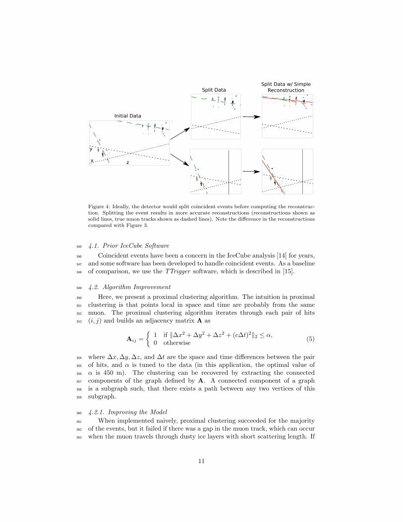
Figure 4: Ideally, the detector would split coincident events before computing the reconstruc-tion. Splitting the event results in more accurate reconstructions (reconstructions shown assolid lines, true muon tracks shown as dashed lines). Note the difference in the reconstructionscompared with Figure 3.
4.1. Prior IceCube Software345
Coincident events have been a concern in the IceCube analysis [14] for years,346
and some software has been developed to handle coincident events. As a baseline347
of comparison, we use the TTrigger software, which is described in [15].348
4.2. Algorithm Improvement349
Here, we present a proximal clustering algorithm. The intuition in proximal350
clustering is that points local in space and time are probably from the same351
muon. The proximal clustering algorithm iterates through each pair of hits352
(i, j) and builds an adjacency matrix A as353
Aij =
{1 if ‖∆x2 + ∆y2 + ∆z2 + (c∆t)2‖2 ≤ α,0 otherwise
(5)
where ∆x,∆y,∆z, and ∆t are the space and time differences between the pair354
of hits, and α is tuned to the data (in this application, the optimal value of355
α is 450 m). The clustering can be recovered by extracting the connected356
components of the graph defined by A. A connected component of a graph357
is a subgraph such, that there exists a path between any two vertices of this358
subgraph.359
4.2.1. Improving the Model360
When implemented naively, proximal clustering succeeded for the majority361
of the events, but it failed if there was a gap in the muon track, which can occur362
when the muon travels through dusty ice layers with short scattering length. If363
11

there is a significantly large gap, the algorithm erroneously separates the hits364
into two clusters.365
To compensate, an additional heuristic is added, track connecting. After the366
data segmentation is finished, track connecting determines if separate clusters367
should be combined. It computes the mean position and time of each cluster,368
and connects a hypothetical muon track T between each pair of subspaces.369
It checks if the speed s of the hypothetical track is within 25% of the speed370
of light c, and it checks that the mean distance between hits and T in both371
clusters is less than 60 m. If T passes both checks, the clusters are combined.372
4.2.2. Adding Robustness to Noise373
Proximal clustering is susceptible to noise. Noise hits close to two disjoint374
tracks will be considered adjacent to both tracks and, thus, can connect the two375
tracks in the adjacency matrix.376
One heuristic that worked well at mitigating this problem was to not use all377
of the hits in building the adjacency matrix. During data collection, some hits378
are flagged as having a local coincidence condition, which indicates that both379
they and a neighboring PMT reported a hit. These hits have a high probability380
of not being noise hits and, thus, exclusively using them to build the adjacency381
matrix mitigates the problem of erroneously connecting two tracks.382
After the proximal clustering algorithm has extracted the tracks from the383
adjacency matrix, the hits not used in the construction of the adjacency matrix384
are simply assigned to the closest reconstructed track.385
4.3. Results386
There were two competing goals for coincident event detection algorithms:387
the algorithm should be conservative enough that events containing single tracks388
are not erroneously split, and aggressive enough that a useful fraction of coin-389
cident events are split correctly. Our algorithm is tuned to keep almost all390
of the single events correctly unsplit, while still correctly splitting 80% of the391
coincident events.392
4.3.1. Measurements393
We modified the reconstruction pipeline shown in Figure 2, in between the394
noise cleaning and the basic reconstruction, by adding a step for coincident event395
detection, as shown in Figure 4. This step takes cleaned data and attempts to396
classify the event as a single-track or multiple-track event.397
We ran each algorithm on two datasets of simulated data. One dataset398
comprised single-muon events, and the other dataset comprised multiple-muon399
events. In each dataset, we measured the classification error E, which is the400
fraction of events that were misclassified. To get a global measurement, we401
computed the total error Etot, defined as402
Etot = wSingleESingle + αwMultipleEMultiple. (6)
12

Table 2: Error Rates for Classification Algorithms
Algorithm ESingle % EMultiple% Etot %
Trivial 0.0 100.0 41.5TTrigger 11.5 31.8 23.7Proximal clustering 0.2 18.9 8.0
For computing Etot, we use wSingle = 0.917 and wMultiple = 0.083, which is403
the frequency in which single-muon and multiple-muon events appear in data404
simulating the distribution of events that trigger the reconstruction algorithm.405
We also include a factor of α in the weighting of the multiple-muon events. This406
factor expresses that mischaracterizing a multiple-muon event as a single-muon407
event degrades the quality of most higher-order analysis more than the reverse408
mischaracterization. In our calculations, we use a value of α = 5.409
We present the results for the coincident event problem by measuring how410
well each algorithm performs at determining the number of subspaces in an411
event.412
There are two natural comparisons for the work: the prior software TTrigger,413
as well as the trivial algorithm, which always classifies each event as a single-414
track event. Clearly, the latter will always get the single-track events correct,415
and always get the multiple-track events wrong. We provide a comparison of416
these techniques in Table 2. As shown, the new algorithm classifies the number417
of muons in the detector 66% better than TTrigger.418
5. Conclusions419
We found that significant improvements can be achieved in the IceCube’s on-420
line track reconstruction by employing some classical data analysis algorithms.421
Optimizing data filtering and refining the least-square model have led to signif-422
icant improvements in the accuracy of the reconstruction direction. The new423
reconstruction software is fast enough to run on-site, and is now included in all424
IceCube analyses.425
We also looked at the problem of determining the number of muons in the426
detector. We found that proximal clustering with some basic heuristics could427
correctly determine whether an event contained a single muon or multiple muons428
with less than 2% error, yielding a 66% improvement over the prior software.429
References430
[1] IceCube Collaboration, IceCube webpage, http://icecube.wisc.edu/.431
[2] A. Achterberg et al., First year performance of the IceCube neutrino tele-432
scope, Astroparticle Physics 26 (3) (2006) 155–173.433
13

[3] J.Ahrens et al., Muon track reconstruction and data selection techniques in434
AMANDA, Nuclear Instruments and Methods in Physics Research Section435
A 524 (2004) 169–194.436
[4] M. G. Aartsen et al., Measurement of South Pole ice transparency with the437
IceCube LED calibration system IceCube Collaboration, Nuclear Instru-438
ments and Methods in Physics Research Section A (2013) 73–89.439
[5] M. Ackermann et al., Optical properties of deep glacial ice at the south440
pole, Journal of Geophysical Research 111 (D13) (2006) D13203.441
[6] F. Hirsch, on behalf of the ATLAS collaboration, Tracking and vertexing442
with the ATLAS detector at the LHC, Nuclear Instruments and Methods443
in Physics Research Section A: Accelerators, Spectrometers, Detectors and444
Associated Equipment 650 (1) (2011) 218–223.445
[7] R. S. Chivukulaa, M. Goldena, E. H. Simmons, Multi-jet physics at hadron446
colliders, Nuclear Physics B 363 (1) (1991) 83–96.447
[8] S. Ellis, J. Huston, K. Hatakeyama, P. Loch, M. Tonnesmann, Jets in448
hadron–hadron collisions, Progress in Particle and Nuclear Physics (60)449
(2008) 484–551.450
[9] R. Abbasi et al., Calibration and characterization of the IceCube photomul-451
tiplier tube, Nuclear Instruments and Methods in Physics Research Section452
A 618 (2010) 139–152.453
[10] R. Abbasi et al., The icecube data acquisition system: Signal capture, dig-454
itization, and timestamping, Nuclear Instruments and Methods in Physics455
Research Section A 601 (3) (2009) 294–316.456
[11] M. Ackermann, Searches for signals from cosmic point-like sources of high457
energy neutrinos in 5 years of AMANDA-II data, Ph.D. thesis, Humboldt-458
Universitat zu Berlin (2006).459
[12] V. Stenger, Track fitting for DUMAND-II Octagon Array, Tech. rep., Uni-460
versity of Hawaii at Manoa (1990).461
[13] S. Boyd, L. Vandenberghe, Convex Optimization, Cambridge University462
Press, Pages 299, 2009.463
[14] R. Abbasi et al., Measurement of the atmospheric neutrino energy spectrum464
from 100 GeV to 400 TeV with IceCube, Physical Review D 83 (1).465
[15] D. Chirkin, Measurement of the atmospheric neutrino energy spectrum466
with IceCube, Proceedings of the 31st ICRC.467
14