Embed Size (px)
Citation preview

11
INNOVATIVE SOLUTIONS TO COMPLEX PROBLEMS
www.ara.com
© 2017 Applied Research Associates, Inc. ARA Proprietary
PSA 2017 Paper 21892
Improved Tornado Missile Risk Analysis Using Nonlinear Finite Element Analysis of Nuclear Power Plant Structures
September 25, 2017

www.ara.com © 2017 Applied Research Associates, Inc. ARA Proprietary
INNOVATIVE SOLUTIONS TO COMPLEX PROBLEMS
Authors:Claudia Navarro-NorthrupRobert T. Bocchieri, Ph.D.Virginia PhanJeffrey C. SciaudoneLawrence A. Twisdale, Ph.D.
Applied Research Associates, Inc.95 1st Street, Suite 100, Los Altos, CA 94022
Improved Tornado Missile Risk Analysis Using Nonlinear Finite Element Analysis of Nuclear Power Plant Structures
2

www.ara.com © 2017 Applied Research Associates, Inc. ARA Proprietary
INNOVATIVE SOLUTIONS TO COMPLEX PROBLEMS
TORMIS computer code
• Developed to estimate the probability of damage to nuclear power plant structures from debris
missile impacts in extreme winds.
• Relies on calculations for critical damage to a structure.
Critical damage to power plant structures
• Results in loss of function to the plant structure (e.g., crimping of exhaust).
• Each type of missile causes critical damage at a different impact velocity.
• Knowing this critical velocity is an important component of performing this risk analysis.
Analytical methods (e.g., SDOF) for damage analysis
• For some target/missile combinations, test data and simple analytical methods exist to predict
damage.
• Can require many conservative assumptions.
• May result in unnecessarily low critical velocities.
Nonlinear dynamic FEA
• More accurate analysis of impact damage.
• Higher critical velocities are calculated, leading to lower risk numbers.
• Now a practical and cost-effective part of TORMIS risk analysis.
Overview
3
www.ara.com © 2017 Applied Research Associates, Inc. ARA Proprietary
INNOVATIVE SOLUTIONS TO COMPLEX PROBLEMS
Nonlinear finite element analysis (FEA) can model the complex, dynamic target-
missile interaction to determine accurate critical missile velocities.
‘Soft’ missiles are hard to assess with simplistic loading methods.
• These missiles crush significantly during impact, affecting the load applied to the target.
• Target response affects the missile crushing and trajectory.
• Important because they can have a high hit frequency.
Real targets often have complex boundary conditions (BCs) that affect the
target-missile interaction.
• Ignoring or simplifying the BCs can lead to much lower critical missile velocities.
Many target-missile configurations can be analyzed to determine the critical
impact location and velocity.
• Crimping is critical failure mode that can be assessed with FEA.
Overview
4

www.ara.com © 2017 Applied Research Associates, Inc. ARA Proprietary
INNOVATIVE SOLUTIONS TO COMPLEX PROBLEMS
‘Soft’ missiles are missiles that are
weak compared to the target.
• Experience significant deformation during
impact.
• Generally higher hit frequencies.
• Examples include metal siding, steel
grating, and wood planks.
‘Hard’ missiles are comparable to or
stiffer/stronger than the target.
• Hard missiles have little deformation.
• Examples include a wide flange beam and a
channel section beam.
Soft Missiles
5
Metal Siding
(Soft Missile)
Steel Grating
(Soft Missile)
Wide Flange Beam
(Hard Missile)
MissileDepth
(in)
Width
(in)
Length
(ft)
Weight
(lb)
Metal Siding 24 3.6 20 255
Steel Grating 24 1.3 6 74
Wide Flange 14 5.0 15 390

www.ara.com © 2017 Applied Research Associates, Inc. ARA Proprietary
INNOVATIVE SOLUTIONS TO COMPLEX PROBLEMS
Crimping is an important failure mode for
exhaust pipes.
• Exhausts from diesel generators and steam lines.
• These exhaust pipes have minimum required flow
rates to function properly.
Target description:
• 16-in diameter exhaust pipe with a rigid constraint
at the bottom.
• Pipe is in contact with a deformable roof sleeve.
• The concrete roof penetration is modeled as rigid.
Exhaust Pipe Crimping
6
16-in Exhaust Pipe
Roof
Sleeve
Roof
Penetration
Constraint
Exhaust
Pipe

www.ara.com © 2017 Applied Research Associates, Inc. ARA Proprietary
INNOVATIVE SOLUTIONS TO COMPLEX PROBLEMS
Metal siding impact of
16-in exhaust pipe at
540 fps.
• Pipe shown as semi-
transparent.
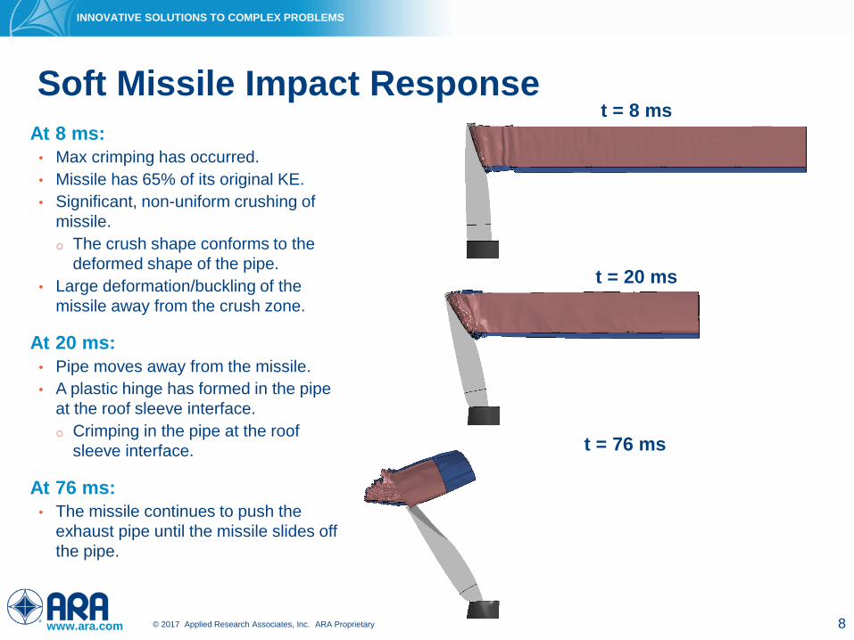
Soft Missile Impact Response
7
www.ara.com © 2017 Applied Research Associates, Inc. ARA Proprietary
INNOVATIVE SOLUTIONS TO COMPLEX PROBLEMS
At 8 ms:
• Max crimping has occurred.
• Missile has 65% of its original KE.
• Significant, non-uniform crushing of
missile.
o The crush shape conforms to the
deformed shape of the pipe.
• Large deformation/buckling of the
missile away from the crush zone.
At 20 ms:
• Pipe moves away from the missile.
• A plastic hinge has formed in the pipe
at the roof sleeve interface.
o Crimping in the pipe at the roof
sleeve interface.
At 76 ms:
• The missile continues to push the
exhaust pipe until the missile slides off
the pipe.
Soft Missile Impact Response
8
t = 8 ms
t = 20 ms
t = 76 ms
www.ara.com © 2017 Applied Research Associates, Inc. ARA Proprietary
INNOVATIVE SOLUTIONS TO COMPLEX PROBLEMS
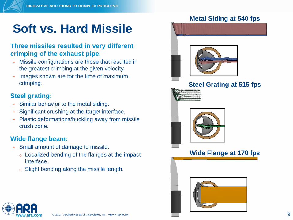
Wide Flange at 170 fps
Three missiles resulted in very different
crimping of the exhaust pipe.
• Missile configurations are those that resulted in
the greatest crimping at the given velocity.
• Images shown are for the time of maximum
crimping.
Steel grating:
• Similar behavior to the metal siding.
• Significant crushing at the target interface.
• Plastic deformations/buckling away from missile
crush zone.
Wide flange beam:
• Small amount of damage to missile.
o Localized bending of the flanges at the impact
interface.
o Slight bending along the missile length.
Soft vs. Hard Missile
9
Metal Siding at 540 fps
Steel Grating at 515 fps
www.ara.com © 2017 Applied Research Associates, Inc. ARA Proprietary
INNOVATIVE SOLUTIONS TO COMPLEX PROBLEMS
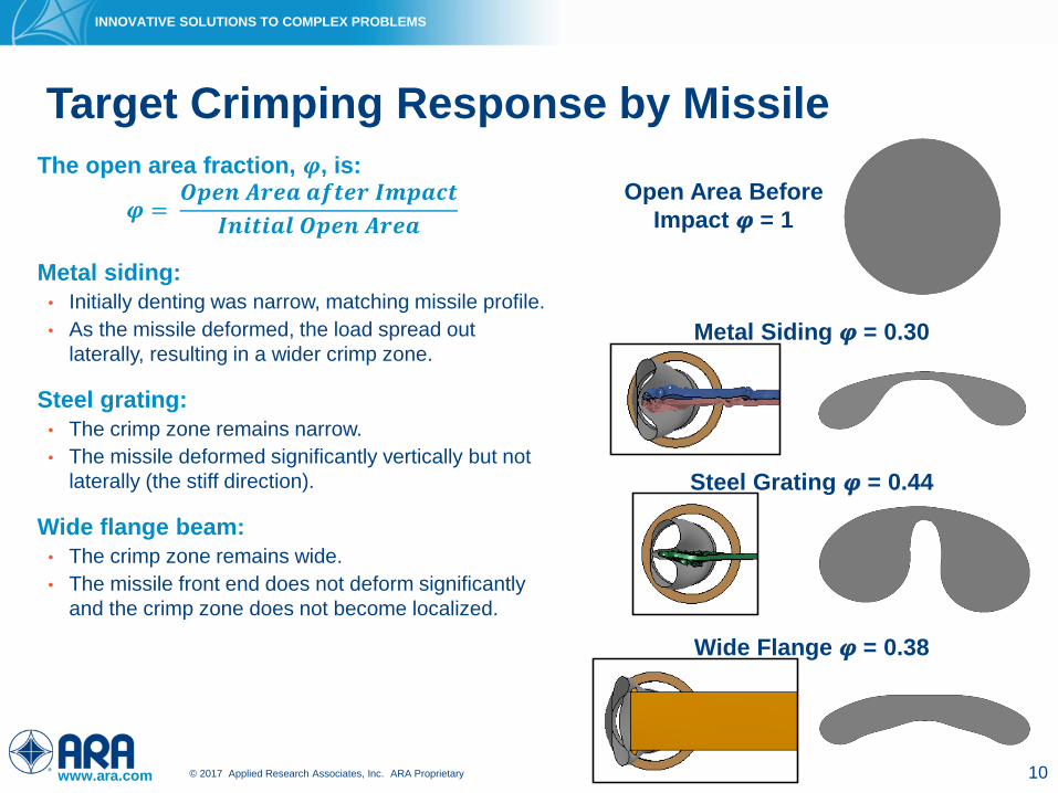
Wide Flange 𝝋 = 0.38
The open area fraction, 𝝋, is:
𝝋 =𝑶𝒑𝒆𝒏 𝑨𝒓𝒆𝒂 𝒂𝒇𝒕𝒆𝒓 𝑰𝒎𝒑𝒂𝒄𝒕
𝑰𝒏𝒊𝒕𝒊𝒂𝒍 𝑶𝒑𝒆𝒏 𝑨𝒓𝒆𝒂
Metal siding:
• Initially denting was narrow, matching missile profile.
• As the missile deformed, the load spread out
laterally, resulting in a wider crimp zone.
Steel grating:
• The crimp zone remains narrow.
• The missile deformed significantly vertically but not
laterally (the stiff direction).
Wide flange beam:
• The crimp zone remains wide.
• The missile front end does not deform significantly
and the crimp zone does not become localized.
Target Crimping Response by Missile
10
Metal Siding 𝝋 = 0.30
Steel Grating 𝝋 = 0.44
Open Area Before
Impact 𝝋 = 1
www.ara.com © 2017 Applied Research Associates, Inc. ARA Proprietary
INNOVATIVE SOLUTIONS TO COMPLEX PROBLEMS
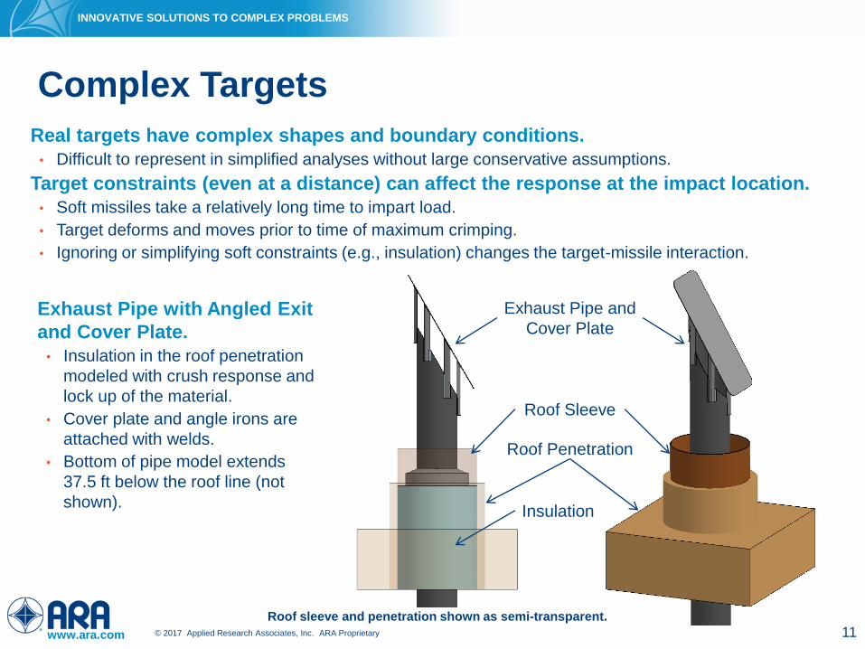
Real targets have complex shapes and boundary conditions.
• Difficult to represent in simplified analyses without large conservative assumptions.
Target constraints (even at a distance) can affect the response at the impact location.
• Soft missiles take a relatively long time to impart load.
• Target deforms and moves prior to time of maximum crimping.
• Ignoring or simplifying soft constraints (e.g., insulation) changes the target-missile interaction.
Complex Targets
11
Roof Sleeve
Exhaust Pipe and
Cover Plate
Roof Penetration
Roof sleeve and penetration shown as semi-transparent.
Insulation
Exhaust Pipe with Angled Exit
and Cover Plate.
• Insulation in the roof penetration
modeled with crush response and
lock up of the material.
• Cover plate and angle irons are
attached with welds.
• Bottom of pipe model extends
37.5 ft below the roof line (not
shown).

www.ara.com © 2017 Applied Research Associates, Inc. ARA Proprietary
INNOVATIVE SOLUTIONS TO COMPLEX PROBLEMS
Metal siding impact of angled exit exhaust pipe with cover plate at 240 fps.
• Pipe shown as semi-transparent.
• Missile rebounds at late time.
Complex Target Impact Response
12
www.ara.com © 2017 Applied Research Associates, Inc. ARA Proprietary
INNOVATIVE SOLUTIONS TO COMPLEX PROBLEMS
At 6 ms:
• Missile is engaged with pipe and cover plate.
o Localized crushing at the interface with target.
• Localized deformation of the exhaust pipe and
cover plate.
• Most of the welds are still intact.
At 20 ms:
• The front of the metal siding has started to buckle.
• The exhaust pipe has begun to sway back.
• Maximum crimping has occurred and the front of
the exhaust pipe has impacted the back of the
pipe.
At 34 ms:
• Significant buckling of the missile.
• All welds in the target have failed.
At 82 ms:
• The missile has buckled along its length, well away
from the target interface.
Complex Target Impact Response
13
t = 6 ms t = 20 ms
t = 34 ms t = 82 ms
Partial missile shown.

www.ara.com © 2017 Applied Research Associates, Inc. ARA Proprietary
INNOVATIVE SOLUTIONS TO COMPLEX PROBLEMS
Cover plate inhibits deflection
of the metal siding away from
the exhaust pipe.
The buckling of the missile at
multiple missile locations has
changed loading on the target.
• Buckled regions reduce load
applied and deceleration of
missile.
• Missile buckling, and target
deformation, has affected the
missile trajectory, allowing the
missile to deflect vertically and
laterally.
Complex Target Impact Response
14
t = 82 ms
Side View
Top View

www.ara.com © 2017 Applied Research Associates, Inc. ARA Proprietary
INNOVATIVE SOLUTIONS TO COMPLEX PROBLEMS
In previous simulation, a deformable
insulation constitutive model was
used for the crush response and
lock up of the material.
• Conservatively modeling the insulation as
rigid provides a stiff constraint that
maximizes crimping.
• Ignoring the insulation results in less
crimping
o The air gap allows the pipe to sway out
of the way during impact.
Impacts to 3 models with a wide
flange beam at 112 fps give very
different responses.
Insulation Modeling
1515
t = 6 ms
t = 20 ms
t = 34 ms
t = 82 msPartial missile shown. The roof penetration, roof sleeve,
and insulation are all shown as semi-transparent.
No
InsulationRigid
Insulation
Insulation 𝝋
Rigid 0.29
Deformable 0.50
None 0.57
Deformable
Insulation
t = 34 ms
t = 24 ms
www.ara.com © 2017 Applied Research Associates, Inc. ARA Proprietary
INNOVATIVE SOLUTIONS TO COMPLEX PROBLEMS
Many different target-missile
configurations can be analyzed.
• Critical location for complex targets and soft
missiles depends on the target-missile
interaction.
• Not known a-priori.
Configuration A:
• Lowest missile impact location without impacting
roof sleeve.
Configuration B:
• Exhaust pipe rotated so the missile impacted the
exhaust pipe to the side of the angle irons.
Configuration C:
• The missile was rotated 90˚.
Configuration D:
• Missile impacts the tallest side (rear) of the
angled pipe.
Complex Target – Critical Impact Location
1616
Configuration A Configuration B
Partial missile shown.
Configuration C Configuration D
www.ara.com © 2017 Applied Research Associates, Inc. ARA Proprietary
INNOVATIVE SOLUTIONS TO COMPLEX PROBLEMS
1717
Configuration A Configuration B
Pipe shown as semi-transparent.
Configuration C Configuration D
Complex Target – Critical Impact Location
www.ara.com © 2017 Applied Research Associates, Inc. ARA Proprietary
INNOVATIVE SOLUTIONS TO COMPLEX PROBLEMS
Plots of open area fraction (𝝋) versus
velocity highlight the critical configurations.
Configuration A:
• Analyzed at 240 fps and 250 fps with little change
in 𝝋.
• At 240 fps, the missile has pushed the front of the
exhaust pipe against the back of the pipe, not
allowing for any more crimping.
Configuration B:
• Less crimping than Configuration A.
• Impacting higher on the pipe on more of the curved
exhaust face reduces the amount of crimping at
the same velocity.
Configuration C:
• The least effective at pipe crimping.
Configuration D:
• Most effective at crimping.
Critical Impact Location
1818
A B C D

www.ara.com © 2017 Applied Research Associates, Inc. ARA Proprietary
INNOVATIVE SOLUTIONS TO COMPLEX PROBLEMS
Nonlinear FEA using LS-DYNA was demonstrated to accurately model complex target-
missile interaction
• Many of the behaviors shown cannot be easily, if at all, modeled with simple analytical methods.
Soft missiles crush and deform affecting the target response.
• Soft missiles have a longer impact duration allowing the target to respond and affecting the overall target-
missile interaction.
• Critical impact location varies by missile type.
Constraints and adjacent structures surrounding a target can also affect the target-
missile interaction.
• In particular, soft boundary conditions, such as insulation, result in a very different target response.
LS-DYNA was used for all the FEA shown here.
• LS-DYNA is commercially available (developed by Lawrence Livermore National Laboratory).
• LS-DYNA has an extensive user community that helps validate the code for a variety of applications
including crash, blast, and impact.
Nonlinear dynamic FEA is now a practical and cost-effective part
of TORMIS risk analysis.
Summary
19

www.ara.com © 2017 Applied Research Associates, Inc. ARA Proprietary
INNOVATIVE SOLUTIONS TO COMPLEX PROBLEMS
Questions?
20
A category 2 hurricane has
maximum sustained winds
of 129 mph (189 fps).