Embed Size (px)
Citation preview

1/24
Improved Fidelity Turbocharger Heat Transfer Models for Use in GT-Power
Manish Khare, Les Smith, JLR Jose R. Serrano, Pablo Olmeda, Francisco J. Arnau, UPV-CMT

2/24
Turbocharger efficiency on engine operation is affected by several physical phenomena of different nature:
Turbomachinery internal irreversibility (isentropic efficiency
in comp. & turbine) Mechanical efficiency due to friction in journal & thrust
bearings Internal heat transfer effects from turbine side to oil and to
compressor side External heat transfer effects
Introduction

3/24
In the turbocharger there are complex interactions among different energy fluxes
Turb
ine
Housing
Com
pres
sor
Turbine power Compressor power Mechanical power
Heat powerOil power
C CompTmap
Ts
W QETE
Wη
+= =
Efficiency in turbine maps is a rough simplification of a complex phenomena and seems not enough for a fully predictive modeling of turbocharged engines
Introduction
4/24
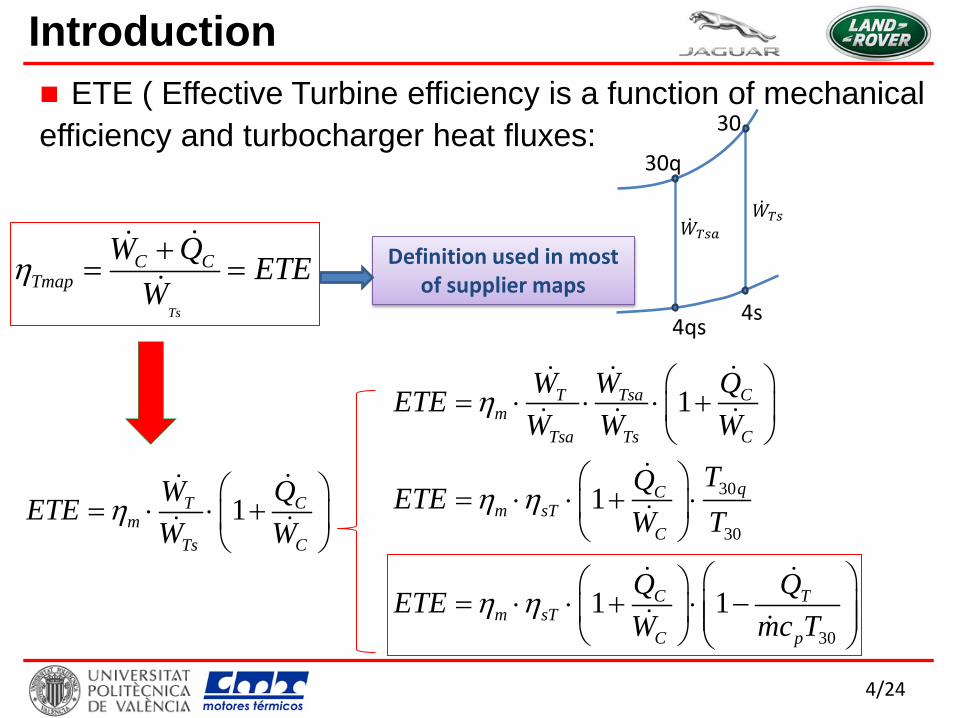
ETE ( Effective Turbine efficiency is a function of mechanical efficiency and turbocharger heat fluxes:
Ts
C CTmap
W Q ETEW
η += =
1T Cm
Ts C
W QETEW W
η
= ⋅ ⋅ +
30
30
1
1
T Tsa Cm
Tsa Ts C
qCm sT
C
W W QETEW W W
TQETEW T
η
η η
= ⋅ ⋅ ⋅ +
= ⋅ ⋅ + ⋅
30
1 1C Tm sT
C p
Q QETEW mc T
η η
= ⋅ ⋅ + ⋅ −
30
30q
4s 4qs
�̇�𝑇𝑇 �̇�𝑇𝑇𝑎
Introduction
Definition used in most of supplier maps

5/24
Direct use of turbine maps efficiency over predicts turbine outlet temperature (due to neglecting heat transfer in the turbine side)
Ts
C CTmap
W Q ETEW
η += =
1T Cm
Ts C
W QETEW W
η
= ⋅ ⋅ +
Introduction
6/24
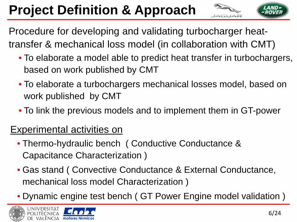
Procedure for developing and validating turbocharger heat-transfer & mechanical loss model (in collaboration with CMT)
• To elaborate a model able to predict heat transfer in turbochargers, based on work published by CMT
• To elaborate a turbochargers mechanical losses model, based on work published by CMT
• To link the previous models and to implement them in GT-power
Experimental activities on
Project Definition & Approach
• Thermo-hydraulic bench ( Conductive Conductance & Capacitance Characterization )
• Gas stand ( Convective Conductance & External Conductance, mechanical loss model Characterization )
• Dynamic engine test bench ( GT Power Engine model validation )

7/24
Mechanical Loss Model Definition Journal Bearing Thrust Bearing
Good correlation between experimental & model data achieved
8/24
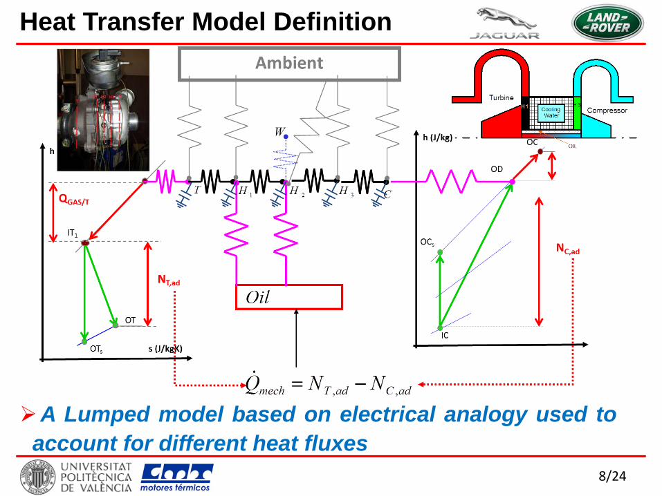
Heat Transfer Model Definition
A Lumped model based on electrical analogy used to account for different heat fluxes

9/24
• Internal Conductances Conductive: KT/H1, KH1/H2, KH2/H3, KH3/C
Convective: GAS/T, H1/oil, H2/oil, C/Air, H2/W or H3/Air
• External Conductances KT/amb, KH1/amb, KH2/amb, KH3/amb, KC/amb
K’T/H1, K’T/H2, K’T/H3, K’T/C, K’H1/H2, K’H1/H3, K’H1/C, K’H2/H3, K’H2/C,
K’H3/C
• Capacitances CT, CH1, CH2, CH3, CC
Heat Transfer Model Definition

10/24
Geometry, properties of the materials and other constant parameters will be provided by an external file & this file links to GT power by a user function
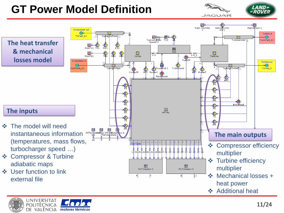
GT Power Model Definition
11/24
The inputs
The model will need instantaneous information (temperatures, mass flows, turbocharger speed …)
Compressor & Turbine adiabatic maps
User function to link external file
The heat transfer & mechanical losses model
Compressor efficiency multiplier
Turbine efficiency multiplier
Mechanical losses + heat power
Additional heat
The main outputs
GT Power Model Definition

12/24
GT Power Model Results: Full Load
Power
COP CIP
AirFlow
No effect was observed for above engine parameters using HTM at FL steady state condition

13/24
GT Power Model Results: Full Load
Turbine Outlet Temperature
HTM is very important for accurately predicting turbine outlet temperature & to some extent compressor outlet temperature
Compressor Outlet Temperature
14/24
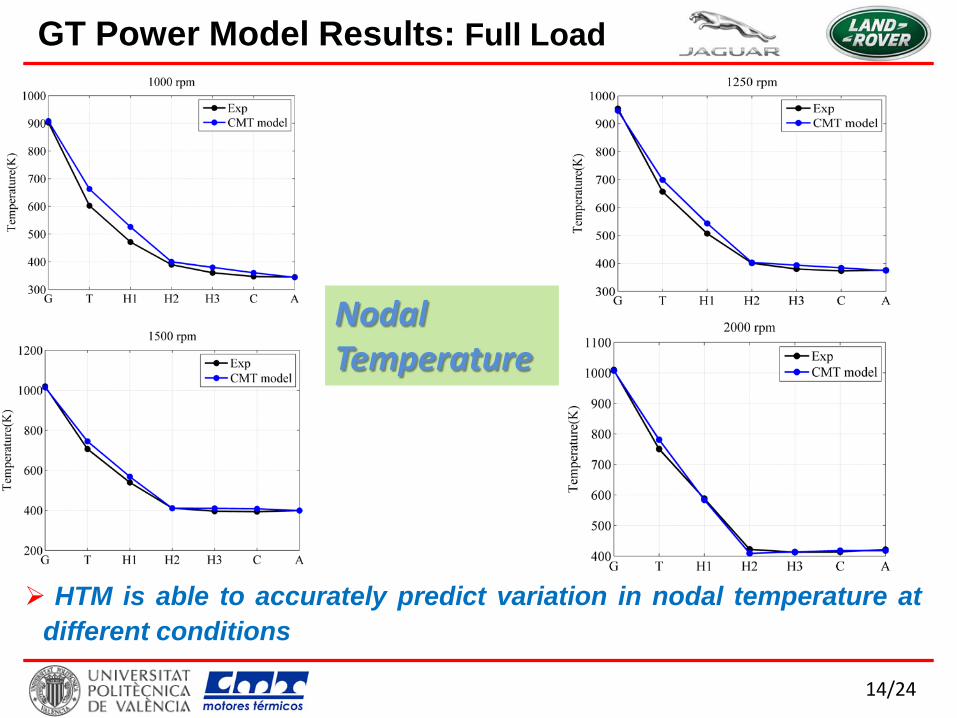
GT Power Model Results: Full Load
Nodal Temperature
HTM is able to accurately predict variation in nodal temperature at different conditions

15/24
GT Power Model Results: Part Load
Power
COP
AirFlow
CIP
Insignificant effect for above engine parameters using HTM at PL steady state condition

16/24
GT Power Model Results: Part Load
Turbine Outlet Temperature Compressor Outlet Temperature
HTM is important for accurately predicting turbine outlet temperature & to some extent compressor outlet temperature
17/24
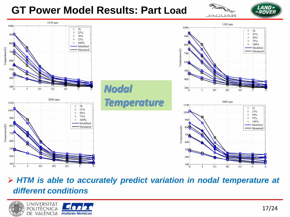
GT Power Model Results: Part Load
Nodal Temperature
HTM is able to accurately predict variation in nodal temperature at different conditions

18/24
Torque COP
Turbo-speed
GT Power Model Results: Transient
Air-flow
Transient results with HTM is better than base model

19/24
COT TOT
GT Power Model Results: Transient
Transient results with HTM is better than base model

20/24
Turbocharger friction losses model (FLM) developed & validated, also linked to GT Power
Turbocharger heat transfer model (HTM) developed & validated, also linked to GT Power
HTM is fundamental for turbine outlet temperature (TOT) prediction
Capability of using a variety of turbocharger map sources while keeping predictability; i.e: adiabatic, hot gas stand, cold gas stand
Clear improvement in load transient predictability Currently validation limited to diesel but work planned for
gasoline to develop database for all JLR turbo machines
Summary

21/24
[1] Serrano, J., Olmeda, P., Arnau, Dombrovsky, A. and Smith, L., ‘’ Methodology to Characterize Heat Transfer Phenomena in Small Automotive Turbochargers: Experiments and Modelling Based Analysis’’, Proceedings of ASME Turbo Expo 2014: Turbine Technical Conference and Exposition, GT2014-25179 , June 16 – 20, 2014, Düsseldorf, Germany [2] Serrano, J., Olmeda, P., Arnau, F. and Reyes-Belmonte, M., 2013, “Importance of Heat Transfer Phenomena in Small Turbochargers for Passenger Car Applications”, SAE Int. J. Engines 6(2), doi:10.4271/2013-01-0576. [3] Serrano, J.R., Olmeda, P., Páez, A., and Vidal, F., 2010, “An Experimental Procedure to Determine Heat Transfer Properties of Turbochargers”, Measurement Science and Technology, 21, 035109 . [4] Serrano, J. R., Olmeda, P., Tiseira, A., García-Cuevas, L. M., and Lefebvre, A., 2013, “Theoretical and Experimental Study of Mechanical Losses in Automotive Turbochargers”, Energy, 55, pp. 888–898. [5] Serrano, J.R., Olmeda, P., Arnau, F.J., Reyes-Belmonte, M.A., Lefebvre, A. and Tartoussi, H. “A Study on the Internal Convection on Small Turbochargers”, submitted to Energy. [6] F. Payri, P. Olmeda, F.A. Arnau, A. Dombrovsky, L. Smith. External heat losses in small turbochargers: Model and experiments. Energy 71 (2014) 534-546
References

22/24

23/24
Compressor efficiency multiplier
•Mechanical power consumed by the compressor
•Using an adiabatic map
•The effect of the heat transfer is included by an efficiency multiplier
• The pseudo compressor power
20 1020 10
sa
map
T TT Tη−
= +
( )20 10= − C C p aW m C T T
ηη
−= = =
−
Cs
diab C C CC
Csmap C C
C
WW Q WK
W W QW
' = + C C CW W Q
positive CQ mean heat flow from the compressor to the housing
GT Power Model Definition

24/24
Turbine efficiency multiplier.
•In order to obtain that temperature from 30 heat effect must be included by mean of the efficiency multiplier
•The pseudo turbine power calculated by GT-Power
( )4 30 30 4a map a sT T T Tη= − −
' = + T T TW W Q
,
,
ηη
+
+
= = =
T T
T T p
T diab TsT
TT adiab
Tsa
W Q
W Q mcWKWW
1
30 1γγ−
−Π
T
T
p
W
mc1
30 1γγ−
−Π
aT
30
30
+= ⋅
aT T
T
TW QW T
GT Power Model Definition
•Using an adiabatic map.

25/24
GT Power Model Definition Mechanical efficiency.
•Pseudo power balance calculated by GT-Power
•Power balance in the turbocharger shaft
•Friction power and addition power due to heat must be extracted from the shaft
= + T C fW W W
' '− = + + T T C C fW Q W Q W
' '= + + +
shaft
T C f C T
W
W W W Q Q