Embed Size (px)
Citation preview

TO: : Mercedes-Benz Dealer Principals, General Managers, Sales Managers, Service Managers, Parts Managers
FROM: Thomas Brunner, Department Manager, Vehicle Compliance and Analysis, Engineering Services
RE: Recall Campaign 2015100007 2015100008 2015100009 – Engine Camshaft Replacement, Model 117/156/172 (CLA-Class, GLA-Class, and SLK-Class) Model Years 2015-2016
DATE: December 16, 2015
IMPORTANT RECALL LAUNCH INFORMATION
This Recall Campaign is being launched today and the 857 affected vehicles will be flagged in VMI. Three separate campaigns have been created to clearly define the proper camshaft repair for each VIN: - 2015100007 (intake) - 2015100008 (intake and exhaust) - 2015100009 (exhaust) Parts: Dealers may order parts as required. Repair Time is approx. 8-9 hours. Currently, parts are available for the 117(CLA) and 156(GLA). The 172 (SLK) does not have all parts available yet. Information will be provided when they become available. Special Tools: All necessary tools specified in the Work Instructions must be on-hand before starting the repairs. Owner Notification: Owner notifications will be sent approximately late December, 2015. What Should Customers Do: Customers may continue to drive their vehicles until the recall is completed. Given this notice, it is a violation of Federal law for a dealer to sell or lease any new Model Years 2015-2016 CLA-Class, GLA-Class, SLK-Class vehicles covered by this notification in dealer inventory until the vehicle has been repaired. This notice provides the information for Dealers to start repairing vehicles. Once the repair is completed, the vehicle may be sold. Dealers are encouraged to check inventory vehicles for recall campaign applicability in VMI, and repair immediately. What’s the Issue: Daimler AG (DAG) has decided that on approximately 857 Model Years 2015-2016 CLA-Class, GLA-Class, and SLK-Class vehicles, the camshaft weld might have been manufactured outside of specfications, where the weld on certain camshafts may not have been placed at the intended position. In the affected vehicles, one or both camshafts could break and damage the engine, leading to a loss of power and causing the engine to stall. If this situation occurs, the engine cannot be restarted.
What We’re Doing: MBUSA has initiated a voluntary recall of all potentially affected vehicles described above. An authorized Mercedes-Benz dealer will replace the engine camshaft on the affected vehicles.
When scheduling customers for an appointment please ensure that you are aware of any open campaigns in VMI so that the customer is advised about the time necessary to complete all campaigns.
MERCEDES-BENZ USA, LLC 303 Perimeter Center North, Suite 202 Atlanta, GA, 30346 Phone: (770) 705-0600 Fax: (770) 705-0117 MBUSA.com

Note: VMI must always be checked before performing campaigns to verify that the campaign is required on a specific vehicle.
Dealers may also identify vehicles subject to a campaign through NetStar by selecting “Campaign” under the Controlling tab. Only vehicles that have been retailed by the respective dealer will be displayed within this program.
While we regret any inconvenience this may cause, MBUSA is determined to maintain a high level of vehicle quality and customer satisfaction.
Please refer all customer inquiries to the Customer Assistance Center at 1-800-FOR-MERCedes (1-800-367-6372).

Campaign No. 2015100007, December 2015
TO: ALL MERCEDES-BENZ CENTERS
SUBJECT: Models 117 (CLA) and 156 (GLA) with Engine 270, Model 172 (SLK) with Engine
274, Model Years 2015 - 2016
Replace Intake Camshaft
This Recall campaign has been initiated because Daimler AG (DAG), the manufacturer of Mercedes-
Benz vehicles, has determined that on certain Model Year 2015-2016 CLA, GLA, SLK vehicles equipped
with four-cylinder gasoline engines, a camshaft weld might have been manufactured outside of
specifications. Due to a production deviation at a supplier, the weld on certain camshafts may not be
placed at the intended position. The subject four-cylinder gasoline engines are designed with two
camshafts, one intake camshaft and one exhaust camshaft. In the affected vehicles the intake camshaft
could break and damage the engine until it stalls. If this situation occurs, the engine cannot be restarted.
An authorized Mercedes-Benz dealer will replace the intake camshaft on the affected vehicles.
Prior to performing this Recall Campaign:
Please check VMI to determine if the vehicle is involved in the Campaign and if it has been
previously repaired.
Please review the entire Recall Campaign bulletin and follow the repair procedure exactly as
described.
Please note that Recall Campaigns do not expire and may also be performed on a vehicle with a
vehicle status indicator.
Approximately 372 vehicles are involved. Order No. P-RC-2015100007 This bulletin has been created and maintained in accordance with MBUSA-SLP S423QH001, Document and Data Control, and MBUSA-SLP S424HH001, Control of Quality Records.

2
P-RC-2015100007
Procedure
Note (applies to camshaft teach-in process to be performed after camshaft has been replaced):
Use DAS/Xentry 09-10-11/15 with add-on 4947 or higher.
Follow the steps exactly as described in DAS/Xentry.
Connect battery charger (battery voltage >12.5V).
Ensure all electrical consumers are switched-off.
In the event of software/SCN update issues, contact Star Diagnosis User Help Desk. Please refer to the
“pre-call” check list before contacting UHD
Refer to Star Diagnosis System (SDS) Best Practices Guide.
1. Replace intake camshaft models 117, 156; refer to WIS: AR05.20-P-6992MT.
Note (Supplemental information to above WIS instructions. Be sure to review all WIS documents
linked to the above WIS instructions before performing the follow supplemental steps):
When removing lower engine compartment panel remove 2 screws (arrows, Figure 1) connecting
front bumper to fender on left and right sides of vehicle. Do not remove bumper.
Do not remove coolant vent line (arrow, Figure 2) from expansion tank (A). Disconnect vent line
(arrow) from valve cover and move to one side.
Do not completely drain cooling system. Lower coolant level then bleed and top-off system on
reassembly.
Figure 1 (Location reference: Inside of right front wheel well)
Figure 2

3
P-RC-2015100007
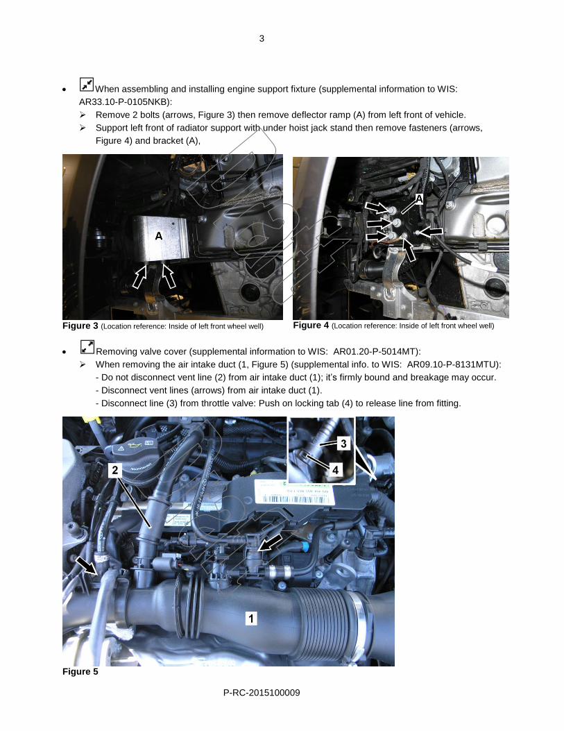
When assembling and installing engine support fixture (supplemental information to WIS:
AR33.10-P-0105NKB):
Remove 2 bolts (arrows, Figure 3) then remove deflector ramp (A) from left front of vehicle.
Support left front of radiator support with under hoist jack stand then remove fasteners (arrows,
Figure 4) and bracket (A),
Figure 3 (Location reference: Inside of left front wheel well)
Figure 4 (Location reference: Inside of left front wheel well)
Removing valve cover (supplemental information to WIS: AR01.20-P-5014MT):
When removing the air intake duct (1, Figure 5) (supplemental info. to WIS: AR09.10-P-8131MTU):
- Do not disconnect vent line (2) from air intake duct (1); it’s firmly bound and breakage may occur.
- Disconnect vent lines (arrows) from air intake duct (1).
- Disconnect line (3) from throttle valve: Push on locking tab (4) to release line from fitting.
Figure 5

4
P-RC-2015100007
- Lift up air intake duct (A, Figure 6) then secure it to base of right wiper arm (arrow) using a small
cargo strap, or large cable tie (shop supply) etc. (allows access to valve cover and components).
Figure 6
When disconnecting engine wiring harness (supplemental information to WIS:
AR0100-P-2410-02MT): Remove pendulum support (B, Figure 6) to allow access to wiring harness
connectors; refer to WIS: AR22.10-P-1125NKB.
Figure 7
When removing vacuum pump (A, Figure 7); (supplemental info to WIS: AR43.05-P-1320MT):
- Move large coolant pipe (B) in front of vacuum pump (A) to one side:
Disconnect two bolts (arrows) securing coolant pipe (B).
- Remove air intake duct (C) to throttle valve (D):
Remove bolt (E) then remove 4 bolts (F) securing intake duct (C) to throttle valve (D).
Note:
- Throttle valve (D) will also be unfastened along with air intake duct (C) when bolts (F) are removed.
- Be sure to replace 2 seals on throttle valve (D).

5
P-RC-2015100007
Remove top bolt (A, Figure 8) on rear lifting ring (B) then loosen bottom bolt (arrow).
Push lifting ring away from valve cover when removing valve cover (supplemental information to
WIS: AR01.20-P-5014MT).
Figure 8
When installing camshaft holding tools (special tool: 270 589 01 61 00): Loosen bolts securing right
front engine lifting ring (arrow, Figure 9) to allow clearance on intake camshaft (A) side.
Figure 9
Figure 10
When removing camshaft (supplemental information to WIS instructions: AR05.20-P-6992MT):
Remove 2 bolts (arrows, Figure 10) then remove camshaft holders (A).
Installation Note: Install camshaft holders (A) back to original locations on cylinder head,
torque bolts (arrows) to 27.5 Nm
Note: After camshaft replacement is complete proceed to step 3: Perform “Teach-in process camshaft functions”.

6
P-RC-2015100007
2. Replace intake camshaft on Model 172; refer to WIS: AR05.20-P-6992MRA.
Note: (regarding above WIS instructions):
WIS instructions: AR05.20-P-6992MRA are described for removal/installation of camshafts and engine
components for model 205 with engine 274.9. Model 172 is similar.
For instructions on removal/installation of vehicle specific components (panels, air filter housing, etc.)
please refer to model 172 WIS instructions.
Do not completely drain cooling system. Lower coolant level then bleed and top-off system on
reassembly.
Do not remove coolant vent line. Disconnect line and move to one side (refer to WIS: AR01.20-P-
5014MRA).
When removing camshaft (supplemental information to WIS instructions: AR05.20-P-6992MT):
Remove 2 bolts (arrows, Figure 10) then remove camshaft holders (A).
Installation Note: Install camshaft holders (A) back to original locations on cylinder head,
torque bolts (arrows) to 27.5 Nm
After camshaft replacement is complete proceed to step 3: Perform “Teach-in process camshaft
functions”.
3. Connect XENTRY/DAS and perform teach-in process for camshaft functions:
Control units view ME - motor electronics Special procedures
Procedure following the exchange of the component intake camshaft/exhaust camshaft" and process all
available sub-steps in the specified order. Follow on-screen instructions.
Note: Ensure engine temperature is between: 60 ° C and 90 ° C.
Note (regarding WIS documents referenced in this Procedure):
Replacement of parts not listed in the parts table of this Procedure are not claimable under this
campaign. If replacement of additional part(s) is necessary, check coverage prior to submitting
under warranty.

7
P-RC-2015100007
Special Tools
Holding device Socket Socket
Socket wrench bit Test cap Cooler vacuum filling device
Puller Assembly tool Drift
Support fixture (models 117, 156) Pressure hose (model 270)
278 589 00 33 00
272 589 00 43 00
278 589 01 15 00
001 589 65 09 00
246 589 00 62 00
270 589 01 61 00
271 589 00 10 00
270 589 01 07 00
285 589 00 21 00
210 589 00 91 00
119 589 04 63 00

8
P-RC-2015100007
Primary Parts Information
Engine 270
Qty. Part Name Part Number Estimated Replacement
Rate
1 Intake camshaft A 270 050 00 00 100%
2 Screw/bolt A 004 990 37 12
1 O-ring A 021 997 97 45
1 Seal A 270 016 00 80
1 End cover A 000 998 65 90
1 End cover/chain tensioner cover A 270 015 02 00
1 O-ring A 023 997 28 45
18 Screw/bolt A 001 990 57 22
6 Screw/bolt A 002 990 24 22
1 Molded seal A 270 018 00 80
1 O-ring A 021 997 59 45
1 Seal A 270 018 18 00
1 Screw/bolt N 000000 008231
4 Round-wire snap ring A 002 994 13 40 02
4 Intermediate ring A 278 153 00 51
4 Intermediate ring A 278 072 00 51
4 Protective ring A 004 992 29 80
4 O-ring A 018 997 36 45
4 Retaining spring A 278 072 04 43
4 O-ring A 012 997 86 45
4 Sealing ring A 014 997 88 45
4 Sealing ring A 012 997 85 45
1 Compensating ring A 270 094 01 51
1 Fuel line clamp A 006 997 18 90
2 Seal (throttle plates) A 270 096 00 80
1 (10 vehicles) Loctite 7200 cleaner 1) A 010 989 90 71
1 (3 vehicles) Loctite 7063 cleaner spray 2) A 001 986 71 71 10
1 Loctite 5970 sealant A003 989 98 20 10 1)
Loctite 7200 - sufficient for 10 vehicles, submit as Local Purchase - L7200153. Qty. 1, handling is included. 2)
Loctite 7063 - sufficient for 3 vehicles, submit as Local Purchase - L7000282. Qty. 1, handling is included. .

9
P-RC-2015100007
Engine 274
Qty. Part Name Part Number Estimated Replacement
Rate
1 Intake camshaft A 274 050 03 01 100%
1 Chain tensioner cover A 000 997 62 20
1 O-ring A 021 997 60 45
1 O-ring A 025 997 64 48
1 O-ring A 025 997 62 48
2 Screw/bolt A 004 990 37 12
1 O-ring A 021 997 97 45
1 Low-pressure hose clamp A 006 997 18 90
1 Seal A 270 016 00 80
1 Molded seal A 274 018 44 00
1 End cover A 000 998 65 90
1 O-ring A 023 997 28 45
20 Screw/bolt A 001 990 57 22
6 Screw/bolt A 002 990 24 22
1 O-ring A 024 997 80 45
4 Round-wire snap ring A 002 994 13 40 02
4 Intermediate ring A 278 153 00 51
4 Intermediate ring A 278 072 00 51
4 Protective ring A 004 992 29 80
4 O-ring A 018 997 36 45
4 Retaining spring A 278 072 04 43
4 O-ring A 012 997 86 45
4 Sealing ring A 014 997 88 45
4 Sealing ring A 012 997 85 45
4 Hex bolt (vacuum pump) N 000000 003648
1 Fuel line clamp A 006 997 18 90
1 Compensating ring A 274 094 01 51
1 (10 vehicles) Loctite 7200 cleaner 1) A 010 989 90 71
1 (3 vehicles) Loctite 7063 cleaner spray 2) A 001 986 71 71 10
1 Loctite 5970 sealant A003 989 98 20 10 1)
Loctite 7200 - sufficient for 10 vehicles, submit as Local Purchase - L7200153. Qty. 1, handling is included. 2)
Loctite 7063 - sufficient for 3 vehicles, submit as Local Purchase - L7000282. Qty. 1, handling is included.

10
P-RC-2015100007
Note:
Please be aware that only the part number(s) referenced in the Campaign Bulletin is/are
approved for use to repair the vehicle. Repairs performed using any other part(s) will not
have been performed in accordance with the campaign. Accordingly, warranty claims
submitted with reference to an improper part number(s) will be denied.
The following allowable labor operation should be used when submitting a warranty claim for
this repair: Warranty Information
Operation: Replace intake camshaft (02-9371). Includes: Teach in camshaft. Star Diagnosis System (SDS), Connect/disconnect (02-4762)
Damage Code Operation Number Labor Time (hrs.)
05 900 32 7 02-9371 8.6 (model 117)
8.7 (model 156)
7.8 (model 172)
02-4762 0.1
Note Operation Number labor times are subject to change.

Campaign No. 2015100008, December 2015
TO: ALL MERCEDES-BENZ CENTERS
SUBJECT: Model 172 (SLK) with Engine 274, Model Year 2016
Replace Intake and Exhaust Camshafts
This Recall campaign has been initiated because Daimler AG (DAG), the manufacturer of Mercedes-
Benz vehicles, has determined that on certain Model Year 2016 SLK vehicles equipped with four-
cylinder gasoline engines, a camshaft weld might have been manufactured outside of specifications. Due
to a production deviation at a supplier, the weld on certain camshafts may not be placed at the intended
position. The subject four-cylinder gasoline engines are designed with two camshafts, one intake
camshaft and one exhaust camshaft. In the affected vehicles one or both camshafts could break and
damage the engine until it stalls. If this situation occurs, the engine cannot be restarted. An authorized
Mercedes-Benz dealer will replace the relevant camshaft on the affected vehicles.
Prior to performing this Recall Campaign:
Please check VMI to determine if the vehicle is involved in the Campaign and if it has been
previously repaired.
Please review the entire Recall Campaign bulletin and follow the repair procedure exactly as
described.
Please note that Recall Campaigns do not expire and may also be performed on a vehicle with a
vehicle status indicator.
Approximately 2 vehicles are involved. Order No. P-RC-2015100008 This bulletin has been created and maintained in accordance with MBUSA-SLP S423QH001, Document and Data Control, and MBUSA-SLP S424HH001, Control of Quality Records.

2
P-RC-2015100008
Procedure
Note (applies to camshaft teach-in process to be performed after camshaft has been replaced):
Use DAS/Xentry 09-10-11/15 with add-on 4947 or higher.
Follow the steps exactly as described in DAS/Xentry.
Connect battery charger (battery voltage >12.5V).
Ensure all electrical consumers are switched-off.
In the event of software/SCN update issues, contact Star Diagnosis User Help Desk. Please refer to the
“pre-call” check list before contacting UHD
Refer to Star Diagnosis System (SDS) Best Practices Guide.
1. Replace camshafts; refer to WIS: AR05.20-P-6992MRA.
Note: (regarding above WIS instructions):
WIS instructions: AR05.20-P-6992MRA are described for removal/installation of camshafts and engine
components for model 205 with engine 274.9. Model 172 is similar.
For instructions on removal/installation of vehicle specific components (panels, air filter housing, etc.)
please refer to model 172 WIS instructions.
Do not completely drain cooling system. Lower coolant level then bleed and top-off system on
reassembly.
Do not remove coolant vent line. Disconnect line and move to one side (refer to WIS: AR01.20-P-
5014MRA).
When removing camshaft
(supplemental information to WIS
instructions:
AR05.20-P-6992MRA):
Remove 4 bolts (arrows, Figure 1) then
remove 4 camshaft holders (A).
Installation Note: Install camshaft
holders (A) back to original location on
cylinder head,
torque bolts (arrows) to 27.5 Nm
After camshaft replacement is complete
proceed to step 3: Perform “Teach-in
process camshaft functions”.
Figure 1 (shown on engine 270)
2. Connect XENTRY/DAS and perform teach-in process for camshaft functions:
Control units view ME - motor electronics Special procedures
Procedure following the exchange of the component intake camshaft/exhaust camshaft" and process all
available sub-steps in the specified order. Follow on-screen instructions.
Note:
Ensure engine temperature is between: 60 ° C and 90 ° C.

3
P-RC-2015100008
Special Tools
Holding device Socket Socket
Socket wrench bit Test cap Cooler vacuum filling device
Puller Assembly tool Drift
Pressure hose
278 589 00 33 00
272 589 00 43 00
278 589 01 15 00
001 589 65 09 00
270 589 01 61 00
271 589 00 10 00
270 589 01 07 00
285 589 00 21 00
210 589 00 91 00
119 589 04 63 00

4
P-RC-2015100008
Note (regarding WIS documents referenced in this Procedure):
Replacement of parts not listed in the parts table of this Procedure are not claimable under this
campaign. If replacement of additional part(s) is necessary, check coverage prior to submitting
under warranty.
Engine 274
Qty. Part Name Part Number Estimated Replacement
Rate
1 Intake camshaft A 274 050 03 01 100%
Exhaust camshaft A 274 050 01 01
1 Chain tensioner cover A 000 997 62 20
1 O-ring A 021 997 60 45
1 O-ring A 025 997 64 48
1 O-ring A 025 997 62 48
2 Screw/bolt A 004 990 37 12
1 O-ring A 021 997 97 45
1 Low-pressure hose clamp A 006 997 18 90
1 Seal A 270 016 00 80
1 Molded seal A 274 018 44 00
1 End cover A 000 998 65 90
1 O-ring A 023 997 28 45
20 Screw/bolt A 001 990 57 22
6 Screw/bolt A 002 990 24 22
1 O-ring A 024 997 80 45
4 Round-wire snap ring A 002 994 13 40 02
4 Intermediate ring A 278 153 00 51
4 Intermediate ring A 278 072 00 51
4 Protective ring A 004 992 29 80
4 O-ring A 018 997 36 45
4 Retaining spring A 278 072 04 43
4 O-ring A 012 997 86 45
4 Sealing ring A 014 997 88 45
4 Sealing ring A 012 997 85 45
1 Compensating ring A 274 094 01 51
4 Hex bolt (vacuum pump) N 000000 003648
1 Fuel line clamp A 006 997 18 90
1 (10 vehicles) Loctite 7200 cleaner 1) A 010 989 90 71
1 (3 vehicles) Loctite 7063 cleaner spray 2) A 001 986 71 71 10
1 Loctite 5970 sealant A003 989 98 20 10 1)
Loctite 7200 - sufficient for 10 vehicles, submit as Local Purchase - L7200153. Qty. 1, handling is included. 2)
Loctite 7063 - sufficient for 3 vehicles, submit as Local Purchase - L7000282. Qty. 1, handling is included.

5
P-RC-2015100008
Note:
Please be aware that only the part number(s) referenced in the Campaign Bulletin is/are
approved for use to repair the vehicle. Repairs performed using any other part(s) will not
have been performed in accordance with the campaign. Accordingly, warranty claims
submitted with reference to an improper part number(s) will be denied.
The following allowable labor operation should be used when submitting a warranty claim for
this repair: Warranty Information
Operation: Replace exhaust and intake camshafts (02-9372). Includes: Teach in camshaft. Star Diagnosis System (SDS), Connect/disconnect (02-4762)
Damage Code Operation Number Labor Time (hrs.)
05 900 33 7 02-9372 8.0
02-4762 0.1
Note Operation Number labor times are subject to change.

Campaign No. 2015100009, December 2015
TO: ALL MERCEDES-BENZ CENTERS
SUBJECT: Models 117 (CLA) and 156 (GLA) with Engine 270, Model 172 (SLK) with Engine
274, Model Years 2015- 2016
Replace Exhaust Camshaft
This Recall campaign has been initiated because Daimler AG (DAG), the manufacturer of Mercedes-
Benz vehicles, has determined that on certain Model Year 2015-2016 CLA, GLA, SLK vehicles equipped
with four-cylinder gasoline engines, a camshaft weld might have been manufactured outside of
specifications. Due to a production deviation at a supplier, the weld on certain camshafts may not be
placed at the intended position. The subject four-cylinder gasoline engines are designed with two
camshafts, one intake camshaft and one exhaust camshaft. In the affected vehicles the exhaust
camshaft could break and damage the engine until it stalls. If this situation occurs, the engine cannot be
restarted. An authorized Mercedes-Benz dealer will replace the exhaust camshaft on the affected
vehicles.
Prior to performing this Recall Campaign:
Please check VMI to determine if the vehicle is involved in the Campaign and if it has been
previously repaired.
Please review the entire Recall Campaign bulletin and follow the repair procedure exactly as
described.
Please note that Recall Campaigns do not expire and may also be performed on a vehicle with a
vehicle status indicator.
Approximately 483 vehicles are involved. Order No. P-RC-2015100009 This bulletin has been created and maintained in accordance with MBUSA-SLP S423QH001, Document and Data Control, and MBUSA-SLP S424HH001, Control of Quality Records.

2
P-RC-2015100009
Procedure
Note (applies to camshaft teach-in process to be performed after camshaft has been replaced):
Use DAS/Xentry 09-10-11/15 with add-on 4947 or higher.
Follow the steps exactly as described in DAS/Xentry.
Connect battery charger (battery voltage >12.5V).
Ensure all electrical consumers are switched-off.
In the event of software/SCN update issues, contact Star Diagnosis User Help Desk. Please refer to the
“pre-call” check list before contacting UHD
Refer to Star Diagnosis System (SDS) Best Practices Guide.
1. Replace exhaust camshaft models 117, 156; refer to WIS: AR05.20-P-6992MT.
Note (Supplemental information to above WIS instructions. Be sure to review all WIS documents
linked to the above WIS instructions before performing the follow supplemental steps):
When removing lower engine compartment panel remove 2 screws (arrows, Figure 1) connecting
front bumper to fender on left and right sides of vehicle. Do not remove bumper.
Do not remove coolant vent line (arrow, Figure 2) from expansion tank (A). Disconnect vent line
(arrow) from valve cover and move to one side.
Do not completely drain cooling system. Lower coolant level then bleed and top-off system on
reassembly.
Figure 1 (Location reference: Inside of right front wheel well)
Figure 2
3
P-RC-2015100009
When assembling and installing engine support fixture (supplemental information to WIS:
AR33.10-P-0105NKB):
Remove 2 bolts (arrows, Figure 3) then remove deflector ramp (A) from left front of vehicle.
Support left front of radiator support with under hoist jack stand then remove fasteners (arrows,
Figure 4) and bracket (A),
Figure 3 (Location reference: Inside of left front wheel well)
Figure 4 (Location reference: Inside of left front wheel well)
Removing valve cover (supplemental information to WIS: AR01.20-P-5014MT):
When removing the air intake duct (1, Figure 5) (supplemental info. to WIS: AR09.10-P-8131MTU):
- Do not disconnect vent line (2) from air intake duct (1); it’s firmly bound and breakage may occur.
- Disconnect vent lines (arrows) from air intake duct (1).
- Disconnect line (3) from throttle valve: Push on locking tab (4) to release line from fitting.
Figure 5

4
P-RC-2015100009
- Lift up air intake duct (A, Figure 6) then secure it to base of right wiper arm (arrow) using a small
cargo strap, or large cable tie (shop supply) etc. (allows access to valve cover and components).
Figure 6
When disconnecting engine wiring harness (supplemental information to WIS:
AR0100-P-2410-02MT): Remove pendulum support (B, Figure 6) to allow access to wiring harness
connectors; refer to WIS: AR22.10-P-1125NKB.
Figure 7
When removing vacuum pump (A, Figure 7); (supplemental info to WIS: AR43.05-P-1320MT):
- Move large coolant pipe (B) in front of vacuum pump (A) to one side:
Disconnect two bolts (arrows) securing coolant pipe (B).
- Remove air intake duct (C) to throttle valve (D):
Remove bolt (E) then remove 4 bolts (F) securing intake duct (C) to throttle valve (D).
Note:
- Throttle valve (D) will also be unfastened along with air intake duct (C) when bolts (F) are removed.
- Be sure to replace 2 seals on throttle valve (D).

5
P-RC-2015100009
Remove top bolt (A, Figure 8) on rear lifting ring (B) then loosen bottom bolt (arrow).
Push lifting ring away from valve cover when removing valve cover (supplemental information to
WIS: AR01.20-P-5014MT).
Figure 8
When installing camshaft holding tools (special tool: 270 589 01 61 00): Loosen bolts securing right
front engine lifting ring (arrow, Figure 9) to allow clearance on intake camshaft (A) side.
Figure 9
Figure 10
When removing camshaft (supplemental information to WIS instructions: AR05.20-P-6992MT):
Remove 2 bolts (arrows, Figure 10) then remove camshaft holders (A).
Installation Note: Install camshaft holders (A) back to original locations on cylinder head,
torque bolts (arrows) to 27.5 Nm
Note: After camshaft replacement is complete proceed to step 3: Perform “Teach-in process camshaft functions”.

6
P-RC-2015100009
2. Replace exhaust camshaft on Model 172; refer to WIS: AR05.20-P-6992MRA.
Note: (regarding above WIS instructions):
WIS instructions: AR05.20-P-6992MRA are described for removal/installation of camshafts and engine
components for model 205 with engine 274.9. Model 172 is similar.
For instructions on removal/installation of vehicle specific components (panels, air filter housing, etc.)
please refer to model 172 WIS instructions.
Do not completely drain cooling system. Lower coolant level then bleed and top-off system on
reassembly.
Do not remove coolant vent line. Disconnect line and move to one side (refer to WIS: AR01.20-P-
5014MRA).
When removing camshaft (supplemental information to WIS instructions: AR05.20-P-6992MT):
Remove 2 bolts (arrows, Figure 10) then remove camshaft holders (A).
Installation Note: Install camshaft holders (A) back to original location on cylinder head,
torque bolts (arrows) to 27.5 Nm
After camshaft replacement is complete proceed to step 3: Perform “Teach-in process camshaft
functions”.
3. Connect XENTRY/DAS and perform teach-in process for camshaft functions:
Control units view ME - motor electronics Special procedures
Procedure following the exchange of the component intake camshaft/exhaust camshaft" and process all
available sub-steps in the specified order. Follow on-screen instructions.
Note: Ensure engine temperature is between: 60 ° C and 90 ° C.
Note (regarding WIS documents referenced in this Procedure):
Replacement of parts not listed in the parts table of this Procedure are not claimable under this
campaign. If replacement of additional part(s) is necessary, check coverage prior to submitting
under warranty.

7
P-RC-2015100009
Special Tools
Holding device Socket Socket
Socket wrench bit Test cap Cooler vacuum filling device
Puller Assembly tool Drift
Support fixture (models 117, 156) Pressure hose (model 270)
278 589 00 33 00
272 589 00 43 00
278 589 01 15 00
001 589 65 09 00
246 589 00 62 00
270 589 01 61 00
271 589 00 10 00
270 589 01 07 00
285 589 00 21 00
210 589 00 91 00
119 589 04 63 00

8
P-RC-2015100009
Primary Parts Information
Engine 270
Qty. Part Name Part Number Estimated Replacement
Rate
1 Exhaust camshaft A 270 050 46 00
2 Screw/bolt A 004 990 37 12
1 O-ring A 021 997 97 45
1 Seal A 270 016 00 80
1 End cover A 000 998 65 90
1 End cover/chain tensioner cover A 270 015 02 00
1 O-ring A 023 997 28 45
18 Screw/bolt A 001 990 57 22
6 Screw/bolt A 002 990 24 22
1 Molded seal A 270 018 00 80
1 O-ring A 021 997 59 45
1 Seal A 270 018 18 00
1 Screw/bolt N 000000 008231
4 Round-wire snap ring A 002 994 13 40 02
4 Intermediate ring A 278 153 00 51
4 Intermediate ring A 278 072 00 51
4 Protective ring A 004 992 29 80
4 O-ring A 018 997 36 45
4 Retaining spring A 278 072 04 43
4 O-ring A 012 997 86 45
4 Sealing ring A 014 997 88 45
4 Sealing ring A 012 997 85 45
1 Compensating ring A 270 094 01 51
1 Fuel line clamp A 006 997 18 90
2 Seal (throttle plates) A 270 096 00 80
1 (10 vehicles) Loctite 7200 cleaner 1) A 010 989 90 71
1 (3 vehicles) Loctite 7063 cleaner spray 2) A 001 986 71 71 10
1 Loctite 5970 sealant A003 989 98 20 10 1)
Loctite 7200 - sufficient for 10 vehicles, submit as Local Purchase - L7200153. Qty. 1, handling is included. 2)
Loctite 7063 - sufficient for 3 vehicles, submit as Local Purchase - L7000282. Qty. 1, handling is included. .

9
P-RC-2015100009
Engine 274
Qty. Part Name Part Number Estimated Replacement
Rate
1 Exhaust camshaft A 274 050 01 01 100%
1 Chain tensioner cover A 000 997 62 20
1 O-ring A 021 997 60 45
1 O-ring A 025 997 64 48
1 O-ring A 025 997 62 48
2 Screw/bolt A 004 990 37 12
1 O-ring A 021 997 97 45
1 Low-pressure hose clamp A 006 997 18 90
1 Seal A 270 016 00 80
1 Molded seal A 274 018 44 00
1 O-ring A 023 997 28 45
20 Screw/bolt A 001 990 57 22
6 Screw/bolt A 002 990 24 22
1 O-ring A 024 997 80 45
4 Round-wire snap ring A 002 994 13 40 02
4 Intermediate ring A 278 153 00 51
4 Intermediate ring A 278 072 00 51
4 Protective ring A 004 992 29 80
4 O-ring A 018 997 36 45
4 Retaining spring A 278 072 04 43
4 O-ring A 012 997 86 45
4 Sealing ring A 014 997 88 45
4 Sealing ring A 012 997 85 45
4 Hex bolt (vacuum pump) N 000000 003648
1 Fuel line clamp A 006 997 18 90
1 Compensating ring A 274 094 01 51
1 (10 vehicles) Loctite 7200 cleaner 1) A 010 989 90 71
1 (3 vehicles) Loctite 7063 cleaner spray 2) A 001 986 71 71 10
1 Loctite 5970 sealant A003 989 98 20 10 1)
Loctite 7200 - sufficient for 10 vehicles, submit as Local Purchase - L7200153. Qty. 1, handling is included. 2)
Loctite 7063 - sufficient for 3 vehicles, submit as Local Purchase - L7000282. Qty. 1, handling is included.
10
P-RC-2015100009
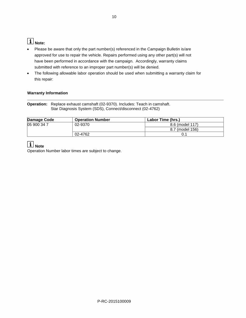
Note:
Please be aware that only the part number(s) referenced in the Campaign Bulletin is/are
approved for use to repair the vehicle. Repairs performed using any other part(s) will not
have been performed in accordance with the campaign. Accordingly, warranty claims
submitted with reference to an improper part number(s) will be denied.
The following allowable labor operation should be used when submitting a warranty claim for
this repair: Warranty Information
Operation: Replace exhaust camshaft (02-9370). Includes: Teach in camshaft. Star Diagnosis System (SDS), Connect/disconnect (02-4762)
Damage Code Operation Number Labor Time (hrs.)
05 900 34 7 02-9370 8.6 (model 117)
8.7 (model 156)
02-4762 0.1
Note Operation Number labor times are subject to change.