Embed Size (px)
Citation preview
NVR User Manual Document Version: 2.0
Date: 2014.02
This document describes the installation, main features, and operations of the NVR.

Important Notices
Important Notices
Thanks for selecting our company’s IPC. Before use, please read through the user’s guide to avoid any unnecessary damage!
This document is applicable to builtin hard disk video recorders, such as the HVRxxxx and VSRxxxx series video recorders.
All functions depend on the actual product. Since the product is subject to updating, our company is not responsible for any difference from this guide and not liable for any dispute over different technical parameters from this guide. The project is subject to any change without notice.
To learn more, please visit our company’s website www.zkivision.comor local office.
NVR User Manual
I
Contents
1 Device Description ............................................................................................................................................ 1
1.1 NVR Overview........................................................................................................................................... 1
1.2 Functions and Features ........................................................................................................................... 1
1.3 Hardware Environment ............................................................................................................................ 3
1.4 Software Environment.............................................................................................................................. 3
1.5 Network Protocols..................................................................................................................................... 4
1.6 Appearance................................................................................................................................................ 4
1.7 Technical parameters ............................................................................................................................... 5
1.8 Panels......................................................................................................................................................... 6
1.8.1 Front Panel ..................................................................................................................................... 6
1.8.2 Rear Panel ...................................................................................................................................... 8
1.9 Mouse Functions..................................................................................................................................... 10
1.10 Input Methods ........................................................................................................................................11
2 Installation and Cable Connection.............................................................................................................. 12
2.1 Hardware Installation.............................................................................................................................. 12
2.2 Hard Disk Installation ............................................................................................................................. 12
2.3 Device Installation................................................................................................................................... 14
2.4 Video Input and Output Connections ................................................................................................... 14
2.5 Audio Input and Output Connections (AIN and AOUT) ..................................................................... 15
2.6 Alarm Output Connections .................................................................................................................... 15
3 System Menus.................................................................................................................................................. 17
3.1 Main Menus ............................................................................................................................................. 17
3.2 Shortcut Menus ....................................................................................................................................... 19
3.2.1 Record Control ............................................................................................................................. 20
3.2.2 PTZ Control .................................................................................................................................. 21
3.3 Main Menu Operations........................................................................................................................... 23
3.4 Record ...................................................................................................................................................... 24
3.4.1 Schedule ....................................................................................................................................... 25
3.4.2 Record Playback .......................................................................................................................... 26
3.4.3 Backup........................................................................................................................................... 28
3.5 Alarm......................................................................................................................................................... 28
3.5.1 Motion Detection .......................................................................................................................... 29
3.5.2 Alarm Input.................................................................................................................................... 30
Contents
II
3.5.3 Access Linkage ............................................................................................................................ 31
3.5.4 Network Alarm .............................................................................................................................. 33
3.5.5 Alarm Output................................................................................................................................. 33
3.5.6 Abnormity ...................................................................................................................................... 34
3.5.7 Digital Alarm.................................................................................................................................. 35
3.6 Setting ...................................................................................................................................................... 35
3.6.1 General.......................................................................................................................................... 35
3.6.2 Network ......................................................................................................................................... 36
3.6.3 Display........................................................................................................................................... 39
3.6.4 Account.......................................................................................................................................... 40
3.6.5 PTZ ................................................................................................................................................ 42
3.6.6 Tour ................................................................................................................................................ 42
3.7 Advanced ................................................................................................................................................. 43
3.7.1 HDD Manage................................................................................................................................ 43
3.7.2 Digital Channel ............................................................................................................................. 44
3.7.3 USB Update.................................................................................................................................. 46
3.7.4 Configuration ................................................................................................................................ 46
3.7.5 Maintenance ................................................................................................................................. 46
3.7.6 Default ........................................................................................................................................... 47
3.7.7 Shut Down .................................................................................................................................... 47
3.8 Information ............................................................................................................................................... 48
3.8.1 HDD Information .......................................................................................................................... 48
3.8.2 BPS ................................................................................................................................................ 48
3.8.3 Log ................................................................................................................................................. 49
3.8.4 Version........................................................................................................................................... 49
4 Quick Start......................................................................................................................................................... 50
4.1 Startup ...................................................................................................................................................... 50
4.2 Login ......................................................................................................................................................... 50
4.3 Shutdown ................................................................................................................................................. 50
4.4 Power Recovery...................................................................................................................................... 50
4.5 Battery Replacement.............................................................................................................................. 50
5 FAQ...................................................................................................................................................................... 51
6 Web Server Client............................................................................................................................................ 53
6.1 Internet Explorer Setting ........................................................................................................................ 53
6.2 Login ......................................................................................................................................................... 54
NVR User Manual
III
6.3 Web Server Client Screen ..................................................................................................................... 54
6.4 Menu Bar.................................................................................................................................................. 55
6.5 Preview Mode.......................................................................................................................................... 55
6.6 Video Connection.................................................................................................................................... 56
6.7 PTZ Control ............................................................................................................................................. 56
6.8 Screen Settings and Others .................................................................................................................. 57
6.9 Record Query .......................................................................................................................................... 58
6.10 System Configuration........................................................................................................................... 60
6.10.1 System Information.................................................................................................................... 60
6.10.2 System Setting ........................................................................................................................... 61
6.10.3 Alarm Function ........................................................................................................................... 62
6.10.4 Advance Option.......................................................................................................................... 63
NVR User Manual
1
1 Device Description
1.1 NVR Overview
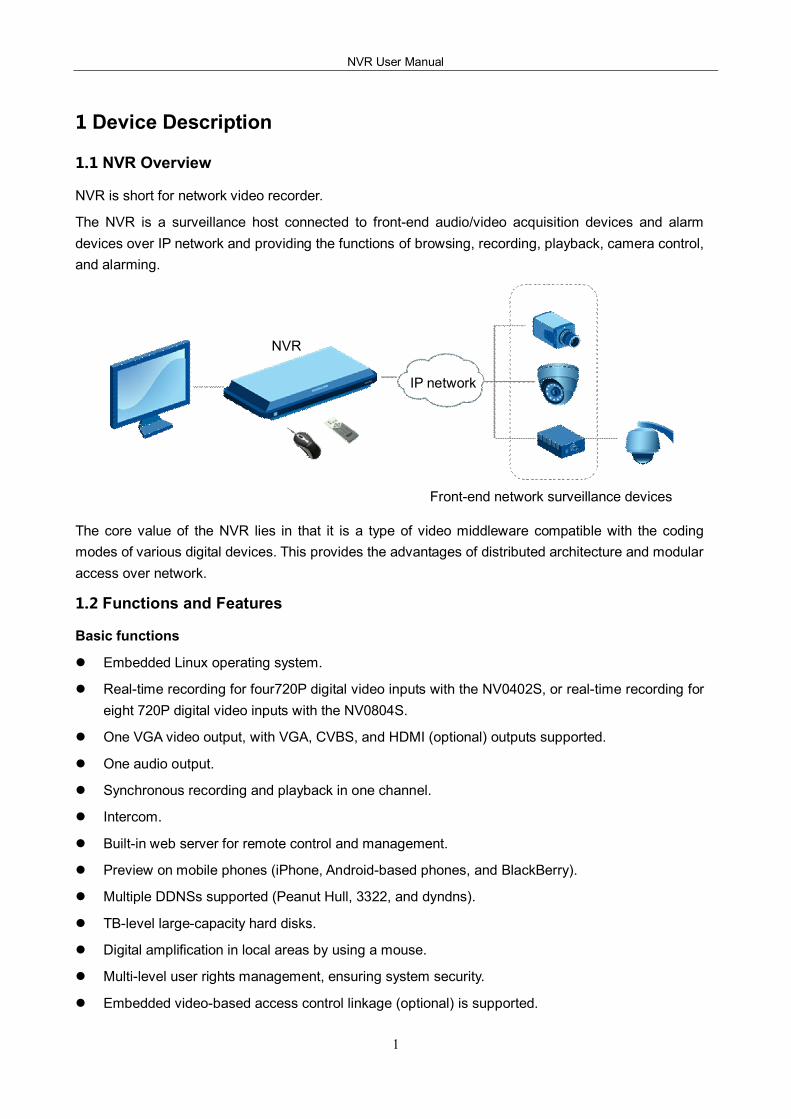
NVR is short for network video recorder.
The NVR is a surveillance host connected to frontend audio/video acquisition devices and alarm devices over IP network and providing the functions of browsing, recording, playback, camera control, and alarming.
The core value of the NVR lies in that it is a type of video middleware compatible with the coding modes of various digital devices. This provides the advantages of distributed architecture and modular access over network.
1.2 Functions and Features
Basic functions
l Embedded Linux operating system.
l Realtime recording for four720P digital video inputs with the NV0402S, or realtime recording for eight 720P digital video inputs with the NV0804S.
l One VGA video output, with VGA, CVBS, and HDMI (optional) outputs supported.
l One audio output.
l Synchronous recording and playback in one channel.
l Intercom.
l Builtin web server for remote control and management.
l Preview on mobile phones (iPhone, Androidbased phones, and BlackBerry).
l Multiple DDNSs supported (Peanut Hull, 3322, and dyndns).
l TBlevel largecapacity hard disks.
l Digital amplification in local areas by using a mouse.
l Multilevel user rights management, ensuring system security.
l Embedded videobased access control linkage (optional) is supported.
NVR
IP network
Frontend network surveillance devices
1 Device Description
2
Storage and backup function
l Two builtin SATA disk interfaces on the NV0402S and four builtin SATA disk interfaces on the NV0804S, supporting TBlevel hard disks.
l Backup based on USB interfaces (such as common USB flash drives and mobile hard disks).
l Download from hard disks over network and backup on a client.
l Nonworking disks in hibernation, facilitating heat dissipation, reducing power consumption, and extending the service life of hard disks.
l Overwrite cyclic recording and noncyclic recording for files on hard disks.
l Dedicated storage format for data, preventing tampering and ensuring data security.
Network function
l One 10M/100M Ethernet interface.
l Parameter setting, realtime video/audio signal browsing, and NVR status check on web pages
l Control over rotation of the pan tilt zoom (PTZ) and camera parameters (such as the aperture and focal length) on the web.
l Alarm handling and system logs check.
l Records search and realtime playback.
l Multilevel user management, enabling flexible and convenient settings of users and user groups with different rights.
l Powerful networking functions and multiple networking modes supported.
l Multiscreen display in remote access over Internet.
Record playback function
l Multiplexing, supporting independent realtime recording in each channel, multichannel search, and singlechannel playback at the same time.
l Multiple record modes (for example, manual mode and action with alarm) and prerecording function.
l Quick search for record files and classification search based on record types.
l Multiple playback modes, including the slow motion, fast forward, reverse play, and framebyframe play modes.
l Display of the accurate event time during the playback of a record.
l Local amplification of any area on the screen during singlescreen and fullscreen playback
l Search for files on a digital video recorder over network during playback.
Realtime surveillance function
l Highdefinition, fine, and soft images on the system screen.
l Display of channel status (for example, recording and video loss) on the channel screen.
l Singlescreen display, multiscreen display, and multichannel tour.
l Free adjustment of the brightness, contrast, saturation, and tone of preview images.
NVR User Manual
3
l Display of the camera name, time, and date on the screen of each digital channel, and free adjustment of the positions of the preceding items.
l VGA output interfaces, providing the surveillance function with monitors.
l Realtime display of recording code streams and space occupied per hour.
l Check of local and remote system logs supported.
Voice function
l One audio output.
l Intercom.
l Synchronous audio and video storage in each channel.
l Synchronous audio and record playback.
Alarm function
l One relay alarm output.
l Prerecording against alarms, prestoring records collected before an alarm is generated, with configurable prerecording time.
l Protective circuits for alarm output interfaces, protecting main devices against damage.
Intelligent operation function
l Operations with a mouse supported.
l Local amplification of any area on the screen during playback.
l Copy and paste of the same settings supported on the menu.
1.3 Hardware Environment
l Power supply: 12V DC.
l Cable connection: Cat 5 network cables and standard AV cables.
l Temperature: Keep the operating temperature within the range from 0ºC to 50ºC. The device may fail when the temperature exceeds the upper or lower limit. Do not install the device above a heat source.
l Humidity: Keep the humidity within the range from 10% to 90%. Do not expose the device to rain or damp environment. Moisture may damage internal components of the device. Do not install the device close to a water source.
l Ventilation: Install the device in a place with proper ventilation and take dustproof measures.
l Installation mode: Install the device horizontally or in a cabinet. Equip the device with a protective enclosure in outdoor environment.
1.4 Software Environment
l Operating system: Embedded Linux.
l Firmware: The latest firmware shall conform to that published on the website. Customized firmware shall conform to the constraints.
1 Device Description
4
1.5 Network Protocols
l Multiple network protocols, including TCP/IP, HTTP, TCP, UDP, ARP, SMTP, FTP, DHCP, DNS, DDNS, NTP, and UPNP.
l Standard ONVIF protocol.
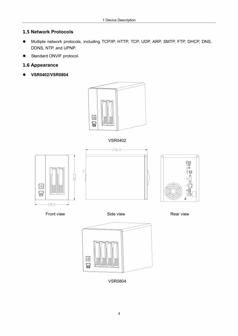
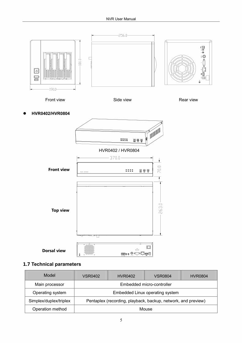
1.6 Appearance
l VSR0402/VSR0804
VSR0402
Front view Side view Rear view
VSR0804
NVR User Manual
5
Front view Side view Rear view
l HVR0402/HVR0804
HVR0402 / HVR0804
1.7 Technical parameters
Model VSR0402 HVR0402 VSR0804 HVR0804
Main processor Embedded microcontroller
Operating system Embedded Linux operating system
Simplex/duplex/triplex Pentaplex (recording, playback, backup, network, and preview)
Operation method Mouse
Front view
Top view
Dorsal view
1 Device Description
6
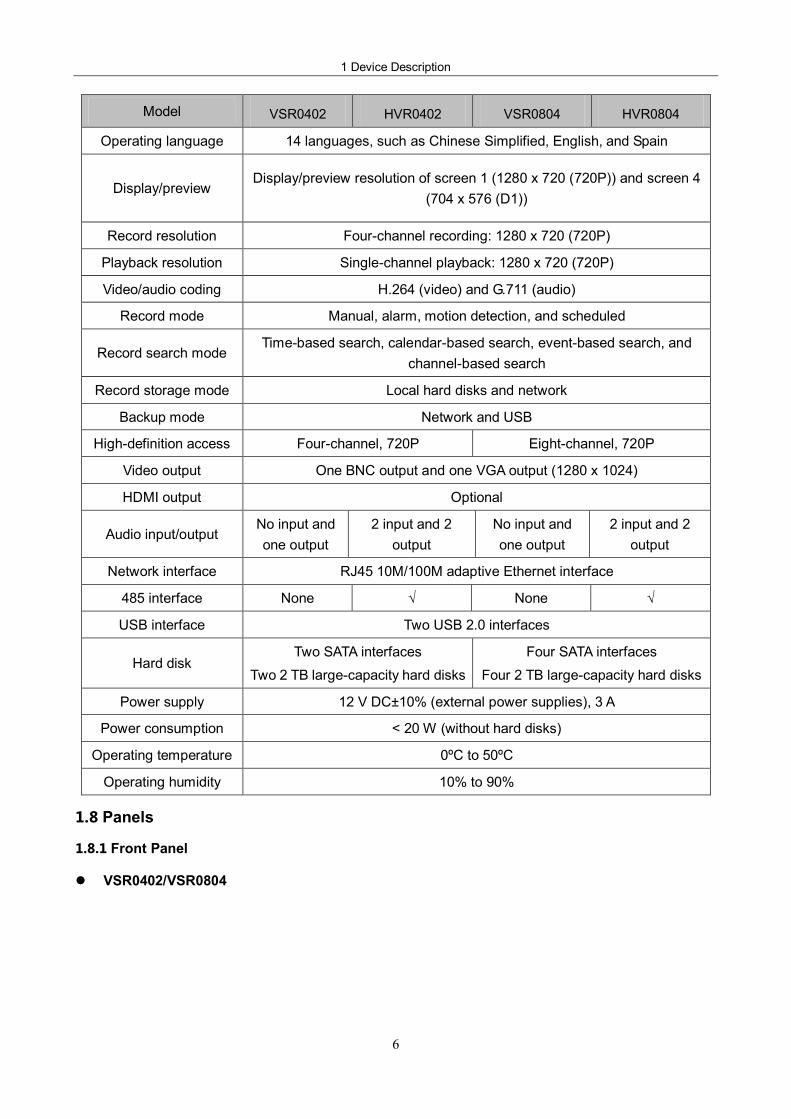
Model VSR0402 HVR0402 VSR0804 HVR0804
Operating language 14 languages, such as Chinese Simplified, English, and Spain
Display/preview Display/preview resolution of screen 1 (1280 x 720 (720P)) and screen 4
(704 x 576 (D1))
Record resolution Fourchannel recording: 1280 x 720 (720P)
Playback resolution Singlechannel playback: 1280 x 720 (720P)
Video/audio coding H.264 (video) and G.711 (audio)
Record mode Manual, alarm, motion detection, and scheduled
Record search mode Timebased search, calendarbased search, eventbased search, and
channelbased search
Record storage mode Local hard disks and network
Backup mode Network and USB
Highdefinition access Fourchannel, 720P Eightchannel, 720P
Video output One BNC output and one VGA output (1280 x 1024)
HDMI output Optional
Audio input/output No input and one output
2 input and 2 output
No input and one output
2 input and 2 output
Network interface RJ45 10M/100M adaptive Ethernet interface
485 interface None √ None √
USB interface Two USB 2.0 interfaces
Hard disk Two SATA interfaces
Two 2 TB largecapacity hard disks Four SATA interfaces
Four 2 TB largecapacity hard disks
Power supply 12 V DC±10% (external power supplies), 3 A
Power consumption < 20 W (without hard disks)
Operating temperature 0ºC to 50ºC
Operating humidity 10% to 90%
1.8 Panels
1.8.1 Front Panel
l VSR0402/VSR0804
NVR User Manual
7
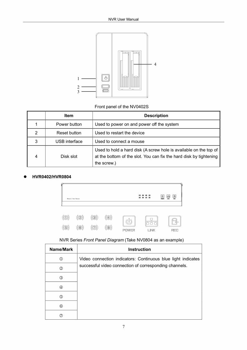
Front panel of the NV0402S
Item Description
1 Power button Used to power on and power off the system
2 Reset button Used to restart the device
3 USB interface Used to connect a mouse
4 Disk slot Used to hold a hard disk (A screw hole is available on the top of at the bottom of the slot. You can fix the hard disk by tightening the screw.)
l HVR0402/HVR0804
NVR Series Front Panel Diagram (Take NV0804 as an example)
Name/Mark Instruction
1
2
3
4
5
6
7
Video connection indicators: Continuous blue light indicates successful video connection of corresponding channels.
1
2 3
4
1 Device Description
8
8
POWER Power indicator: Continuous blue light indicates the power is ready.
LINK Network indicator: Continuous blue light indicates the network is connected.
REC Hard disk video recording indicator: Continuous blue light indicates the hard disk is recording.
1.8.2 Rear Panel
l VSR0402/VSR0804
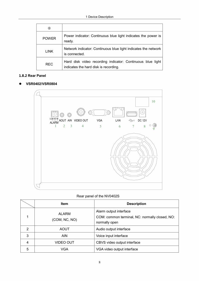
Rear panel of the NV0402S
Item Description
1 ALARM
(COM, NC, NO)
Alarm output interface COM: common terminal, NC: normally closed, NO: normally open
2 AOUT Audio output interface
3 AIN Voice input interface
4 VIDEO OUT CBVS video output interface
5 VGA VGA video output interface
1 2 3 4 5 6 7 8 9
10
NVR User Manual
9
6 LAN RJ45 adaptive Ethernet interface
7 USB interface
8 DC 12V 12 V DC power interface
9 Grounding copper bar
10 Main power switch
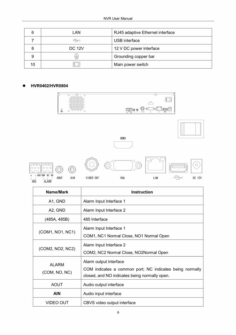
l HVR0402/HVR0804
Name/Mark Instruction
A1, GND Alarm Input Interface 1
A2, GND Alarm Input Interface 2
(485A, 485B) 485 Interface
(COM1, NO1, NC1) Alarm Input Interface 1
COM1, NC1 Normal Close, NO1 Normal Open
(COM2, NO2, NC2) Alarm Input Interface 2
COM2, NC2 Normal Close, NO2Normal Open
ALARM
(COM, NO, NC)
Alarm output interface
COM indicates a common port; NC indicates being normally closed, and NO indicates being normally open.
AOUT Audio output interface
AIN Audio input interface
VIDEO OUT CBVS video output interface
1 Device Description
10
VGA VGA video output interface
LAN RJ45 auto negotiation Ethernet port
USB interface
DC 12V DC12V power interface
HDMI HD video output interface
Main power switch
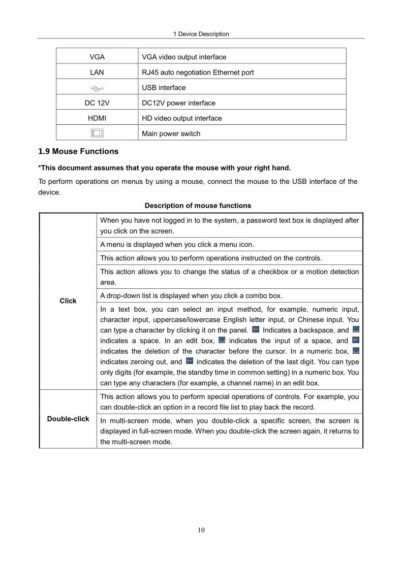
1.9 Mouse Functions
*This document assumes that you operate the mouse with your right hand.
To perform operations on menus by using a mouse, connect the mouse to the USB interface of the device.
Description of mouse functions
When you have not logged in to the system, a password text box is displayed after you click on the screen.
A menu is displayed when you click a menu icon.
This action allows you to perform operations instructed on the controls.
This action allows you to change the status of a checkbox or a motion detection area.
A dropdown list is displayed when you click a combo box. Click
In a text box, you can select an input method, for example, numeric input, character input, uppercase/lowercase English letter input, or Chinese input. You can type a character by clicking it on the panel. Indicates a backspace, and indicates a space. In an edit box, indicates the input of a space, and indicates the deletion of the character before the cursor. In a numeric box, indicates zeroing out, and indicates the deletion of the last digit. You can type only digits (for example, the standby time in common setting) in a numeric box. You can type any characters (for example, a channel name) in an edit box.
This action allows you to perform special operations of controls. For example, you can doubleclick an option in a record file list to play back the record.
Doubleclick In multiscreen mode, when you doubleclick a specific screen, the screen is displayed in fullscreen mode. When you doubleclick the screen again, it returns to the multiscreen mode.
NVR User Manual
11
When you rightclick the screen during realtime surveillance, a shortcut menu is displayed, providing the multiscreen mode, image color, record search, manual recording, alarm input, alarm output, and main menu options. The multiscreen mode is relevant with the number of channels on the device. For example, a fourchannel device displays only a single screen or four screens. The image color applies to the channel that the cursor indicates. In multiscreen mode, the system automatically switches to the single screen of the corresponding channel before the setting of the color image.
Rightclick
This action allows you to exit the current menu without saving the settings.
This action allows you to increase or decrease the number in a numeric box.
This action allows you to switch between options in a combo box. Scroll
This action allows you to page up and page down in a list box.
Move You can select a control or a component of a control in the current coordinates and move it by using the mouse.
Drag This action allows you to select motion detection areas, area settings, and area coverage.
Note: If a mouse cannot be detected after you connect it to the NVR, the mouse is incompatible
with the NVR. Replace the mouse.
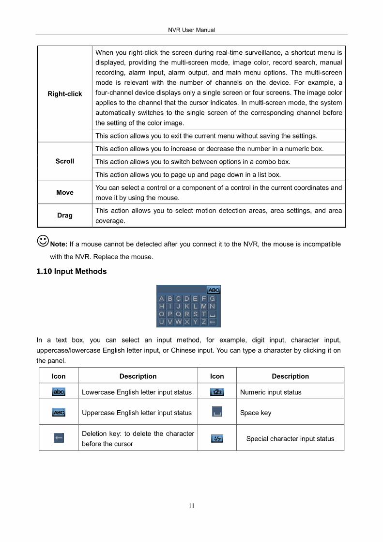
1.10 Input Methods
In a text box, you can select an input method, for example, digit input, character input, uppercase/lowercase English letter input, or Chinese input. You can type a character by clicking it on the panel.
Icon Description Icon Description
Lowercase English letter input status Numeric input status
Uppercase English letter input status Space key
Deletion key: to delete the character before the cursor
Special character input status
2 Installation and Cable Connection
12
2 Installation and Cable Connection
Note the following during the installation:
1. Take out all materials required for the installation.
2. Connect cables (video signal input cables, audio signal input cables, and network cables) as required.
3. Connect the rear panel, front panel, and power supply in sequence.
4. Take out the regulated power adapter or power cable and connect the power supply.
2.1 Hardware Installation
Check After Unpacking
l After you receive the product, check the appearance to see whether it is damaged during the transportation.
l Open the packing box and check the accessories according to the packing list.
l Remove the protective film from the product.
Front Panel and Rear Panel
l Read the descriptions of buttons on the front panel and interfaces on the rear panel in the instruction.
l Check the model on the protective film of the front panel against the order contract.
l Keep the label on the rear panel intact. It is required for aftersales services. Do not tear down or discard the label. Otherwise, no warranty service will be provided. When you call aftersales personnel of the company, provide the serial number of the product.
Internal Check
Check for damage and scratches. Check whether data cables, power cables, and fan power supplies are connected to the main board on the front panel properly.
Precautions (Contact us if you have any doubt)
1. After unpacking, ensure that the materials are consistent with the packing list.
2. Check the voltage, avoiding device damage caused by improper voltage.
3. Check the installation environment. Do not use the device in damp or hightemperature environment. Ensure proper ventilation and keep the air vents unblocked. Lay the device horizontally. Do not install the device in environment with sharp vibration.
2.2 Hard Disk Installation
Check whether hard disks are installed when you install the device for the first time. The NVR supports TBlevel hard disks. Use recommended models of hard disks (7200 rpm or above highspeed hard disks) and SATA disk cables delivered with the device.
l VSR0402/VSR0804
To install a hard disk on the VSR0402, perform the following operations:
NVR User Manual
13
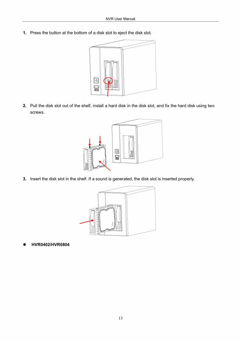
1. Press the button at the bottom of a disk slot to eject the disk slot.
2. Pull the disk slot out of the shelf, install a hard disk in the disk slot, and fix the hard disk using two screws.
3. Insert the disk slot in the shelf. If a sound is generated, the disk slot is inserted properly.
l HVR0402/HVR0804
2 Installation and Cable Connection
14
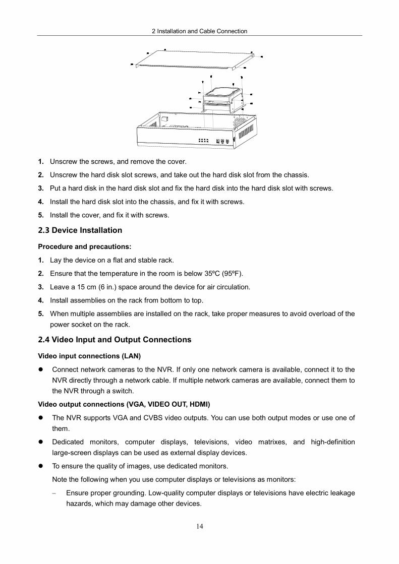
1. Unscrew the screws, and remove the cover.
2. Unscrew the hard disk slot screws, and take out the hard disk slot from the chassis.
3. Put a hard disk in the hard disk slot and fix the hard disk into the hard disk slot with screws.
4. Install the hard disk slot into the chassis, and fix it with screws.
5. Install the cover, and fix it with screws.
2.3 Device Installation
Procedure and precautions:
1. Lay the device on a flat and stable rack.
2. Ensure that the temperature in the room is below 35ºC (95ºF).
3. Leave a 15 cm (6 in.) space around the device for air circulation.
4. Install assemblies on the rack from bottom to top.
5. When multiple assemblies are installed on the rack, take proper measures to avoid overload of the power socket on the rack.
2.4 Video Input and Output Connections
Video input connections (LAN)
l Connect network cameras to the NVR. If only one network camera is available, connect it to the NVR directly through a network cable. If multiple network cameras are available, connect them to the NVR through a switch.
Video output connections (VGA, VIDEO OUT, HDMI)
l The NVR supports VGA and CVBS video outputs. You can use both output modes or use one of them.
l Dedicated monitors, computer displays, televisions, video matrixes, and highdefinition largescreen displays can be used as external display devices.
l To ensure the quality of images, use dedicated monitors.
Note the following when you use computer displays or televisions as monitors:
− Ensure proper grounding. Lowquality computer displays or televisions have electric leakage hazards, which may damage other devices.
NVR User Manual
15
− Perform degaussing regularly to ensure proper operating of the monitors.
− Keep the monitors away from devices that generate strong electromagnetic interference.
− Power off the device after operating for a period to extend the service life of the device.
2.5 Audio Input and Output Connections (AIN and AOUT)
Generally, the audio output signal parameter of the NVR is larger than 200 mV 1K. The NVR can be connected to external lowimpedance headsets and active sound boxes directly or connected to other sound output devices through power amplification drives.
When the NVR is not isolated from external sound boxes or audio monitoring units, output squealing may occur. In this case, take the following measures:
l Adjust the volume of the sound box to be smaller than the threshold at which output squealing occurs.
l Adjust the layout of the audio monitoring units and sound boxes.
l Use soundabsorbing materials during decoration to reduce the reflection of sound and improve the acoustic environment.
l Use audio monitoring units with superb directionality.
2.6 Alarm Output Connections
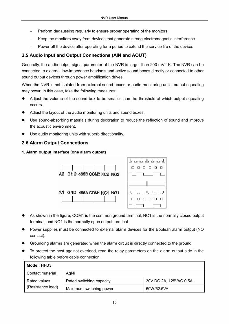
1. Alarm output interface (one alarm output)
l As shown in the figure, COM1 is the common ground terminal, NC1 is the normally closed output terminal, and NO1 is the normally open output terminal.
l Power supplies must be connected to external alarm devices for the Boolean alarm output (NO contact).
l Grounding alarms are generated when the alarm circuit is directly connected to the ground.
l To protect the host against overload, read the relay parameters on the alarm output side in the following table before cable connection.
Model: HFD3
Contact material AgNi
Rated switching capacity 30V DC 2A, 125VAC 0.5A Rated values (Resistance load) Maximum switching power 60W/62.5VA
2 Installation and Cable Connection
16
Maximum switching voltage 220VDC, 250VAC
Maximum switching current 2A
Between contacts with the same polarity 1000 V AC, 1 minute
Between contacts with different polarities 1500 V AC, 1 minute Insulation
Between contacts and coils 2000 V AC, 1 minute
Surge voltage Between contacts with the same polarity 1500 V AC (10 x 160 us)
Connection time 4ms max
Disconnection time 4ms max
Mechanical 100,000,000 times Service life
Electrical 100000 times (30 V DC, 2 A)
Operating temperature
40ºC to +85ºC
Parameters of relays on the alarm output side
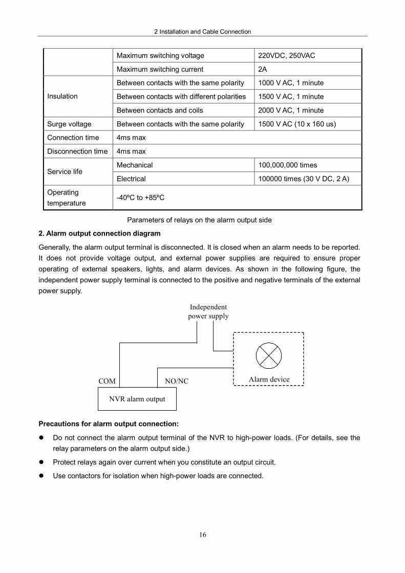
2. Alarm output connection diagram
Generally, the alarm output terminal is disconnected. It is closed when an alarm needs to be reported. It does not provide voltage output, and external power supplies are required to ensure proper operating of external speakers, lights, and alarm devices. As shown in the following figure, the independent power supply terminal is connected to the positive and negative terminals of the external power supply.
Alarm device
NVR alarm output
NO/NC COM
Independent power supply
Precautions for alarm output connection:
l Do not connect the alarm output terminal of the NVR to highpower loads. (For details, see the relay parameters on the alarm output side.)
l Protect relays again over current when you constitute an output circuit.
l Use contactors for isolation when highpower loads are connected.
NVR User Manual
17
3 System Menus
3.1 Main Menus
Main Menu Firstlevel Submenu
Description
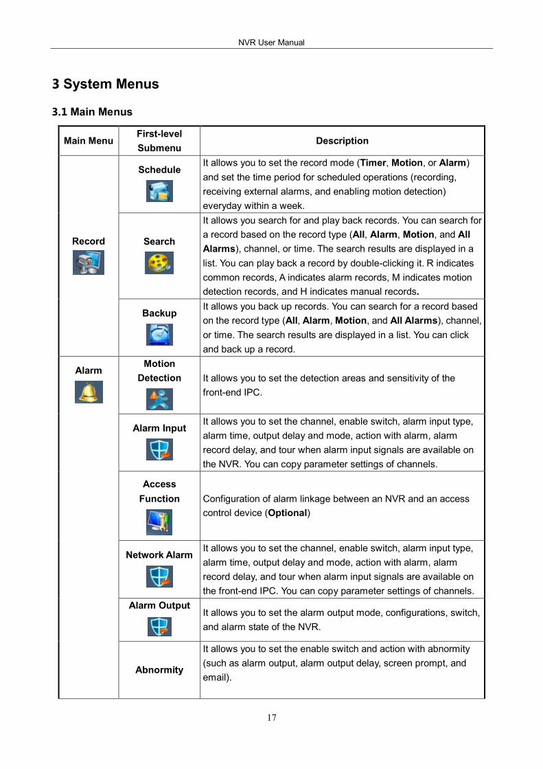
Schedule It allows you to set the record mode (Timer, Motion, or Alarm) and set the time period for scheduled operations (recording, receiving external alarms, and enabling motion detection) everyday within a week.
Search
It allows you search for and play back records. You can search for a record based on the record type (All, Alarm, Motion, and All Alarms), channel, or time. The search results are displayed in a list. You can play back a record by doubleclicking it. R indicates common records, A indicates alarm records, M indicates motion detection records, and H indicates manual records.
Record
Backup It allows you back up records. You can search for a record based on the record type (All, Alarm, Motion, and All Alarms), channel, or time. The search results are displayed in a list. You can click and back up a record.
Motion Detection It allows you to set the detection areas and sensitivity of the
frontend IPC.
Alarm Input It allows you to set the channel, enable switch, alarm input type, alarm time, output delay and mode, action with alarm, alarm record delay, and tour when alarm input signals are available on the NVR. You can copy parameter settings of channels.
Access Function Configuration of alarm linkage between an NVR and an access
control device (Optional)
Network Alarm It allows you to set the channel, enable switch, alarm input type, alarm time, output delay and mode, action with alarm, alarm record delay, and tour when alarm input signals are available on the frontend IPC. You can copy parameter settings of channels.
Alarm Output It allows you to set the alarm output mode, configurations, switch, and alarm state of the NVR.
Alarm
Abnormity
It allows you to set the enable switch and action with abnormity (such as alarm output, alarm output delay, screen prompt, and email).
3 System Menus
18
Main Menu Firstlevel Submenu
Description
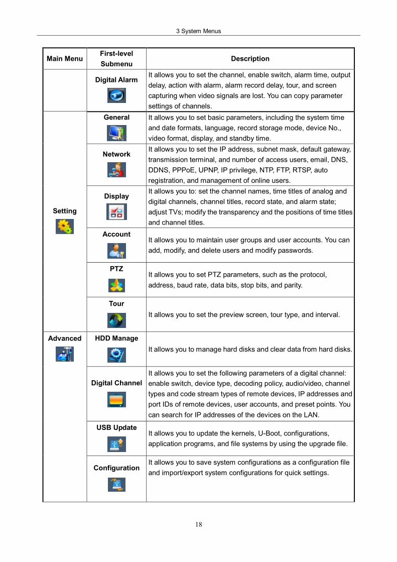
Digital Alarm It allows you to set the channel, enable switch, alarm time, output delay, action with alarm, alarm record delay, tour, and screen capturing when video signals are lost. You can copy parameter settings of channels.
General It allows you to set basic parameters, including the system time and date formats, language, record storage mode, device No., video format, display, and standby time.
Network It allows you to set the IP address, subnet mask, default gateway, transmission terminal, and number of access users, email, DNS, DDNS, PPPoE, UPNP, IP privilege, NTP, FTP, RTSP, auto registration, and management of online users.
Display It allows you to: set the channel names, time titles of analog and digital channels, channel titles, record state, and alarm state; adjust TVs; modify the transparency and the positions of time titles and channel titles.
Account It allows you to maintain user groups and user accounts. You can add, modify, and delete users and modify passwords.
PTZ It allows you to set PTZ parameters, such as the protocol, address, baud rate, data bits, stop bits, and parity.
Setting
Tour It allows you to set the preview screen, tour type, and interval.
HDD Manage It allows you to manage hard disks and clear data from hard disks.
Digital Channel It allows you to set the following parameters of a digital channel: enable switch, device type, decoding policy, audio/video, channel types and code stream types of remote devices, IP addresses and port IDs of remote devices, user accounts, and preset points. You can search for IP addresses of the devices on the LAN.
USB Update It allows you to update the kernels, UBoot, configurations, application programs, and file systems by using the upgrade file.
Advanced
Configuration It allows you to save system configurations as a configuration file and import/export system configurations for quick settings.
NVR User Manual
19
Main Menu Firstlevel Submenu
Description
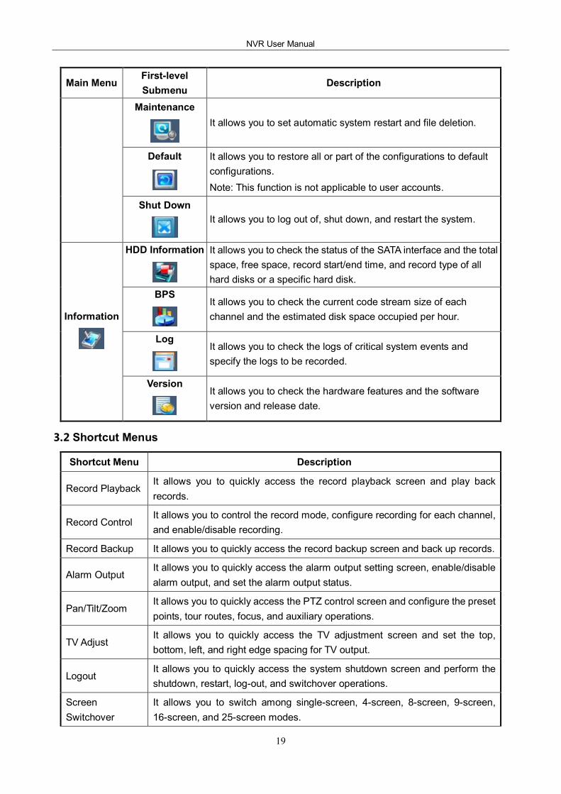
Maintenance It allows you to set automatic system restart and file deletion.
Default It allows you to restore all or part of the configurations to default configurations. Note: This function is not applicable to user accounts.
Shut Down It allows you to log out of, shut down, and restart the system.
HDD Information It allows you to check the status of the SATA interface and the total space, free space, record start/end time, and record type of all hard disks or a specific hard disk.
BPS It allows you to check the current code stream size of each channel and the estimated disk space occupied per hour.
Log It allows you to check the logs of critical system events and specify the logs to be recorded.
Information
Version It allows you to check the hardware features and the software version and release date.
3.2 Shortcut Menus
Shortcut Menu Description
Record Playback It allows you to quickly access the record playback screen and play back records.
Record Control It allows you to control the record mode, configure recording for each channel, and enable/disable recording.
Record Backup It allows you to quickly access the record backup screen and back up records.
Alarm Output It allows you to quickly access the alarm output setting screen, enable/disable alarm output, and set the alarm output status.
Pan/Tilt/Zoom It allows you to quickly access the PTZ control screen and configure the preset points, tour routes, focus, and auxiliary operations.
TV Adjust It allows you to quickly access the TV adjustment screen and set the top, bottom, left, and right edge spacing for TV output.
Logout It allows you to quickly access the system shutdown screen and perform the shutdown, restart, logout, and switchover operations.
Screen Switchover
It allows you to switch among singlescreen, 4screen, 8screen, 9screen, 16screen, and 25screen modes.
3 System Menus
20
Mute It allows you to disable the alarm buzzer. (The alarm buzzer is disabled by default.)
?Notes:
For details about record playback, see section 3.4.2 Record Playback.
For details about record backup, see section 3.4.3 Backup.
For details about alarm output, see section 3.5.5 Alarm Output.
For details about TV adjustment, see section 3.6.3 Display.
For details about system shutdown, see section 3.7.7 Shut Down.
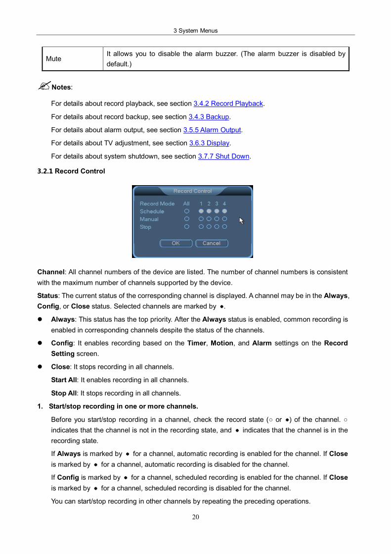
3.2.1 Record Control
Channel: All channel numbers of the device are listed. The number of channel numbers is consistent with the maximum number of channels supported by the device.
Status: The current status of the corresponding channel is displayed. A channel may be in the Always, Config, or Close status. Selected channels are marked by .
l Always: This status has the top priority. After the Always status is enabled, common recording is enabled in corresponding channels despite the status of the channels.
l Config: It enables recording based on the Timer, Motion, and Alarm settings on the Record Setting screen.
l Close: It stops recording in all channels.
Start All: It enables recording in all channels.
Stop All: It stops recording in all channels.
1. Start/stop recording in one or more channels.
Before you start/stop recording in a channel, check the record state ( or ) of the channel. indicates that the channel is not in the recording state, and indicates that the channel is in the recording state.
If Always is marked by for a channel, automatic recording is enabled for the channel. If Close is marked by for a channel, automatic recording is disabled for the channel.
If Config is marked by for a channel, scheduled recording is enabled for the channel. If Close is marked by for a channel, scheduled recording is disabled for the channel.
You can start/stop recording in other channels by repeating the preceding operations.
NVR User Manual
21
2. Start recording in all channels.
To enable automatic recording in all channels, select Always ( ) for All. After automatic recording is enabled in all channels, the NVR starts recording based on the Timer, Motion, and Alarm settings on the Record Setting screen and provides automatic recording channels.
To enable scheduled recording in all channels, select Config ( ) for All. After scheduled recording is enabled in all channels, the recording stops in all channels despite the scheduled settings on the Record Setting screen.
3. Stop recording in all channels.
To stop recording in all channels, select Close ( ) for All. Recording then stops despite the status of the channels.
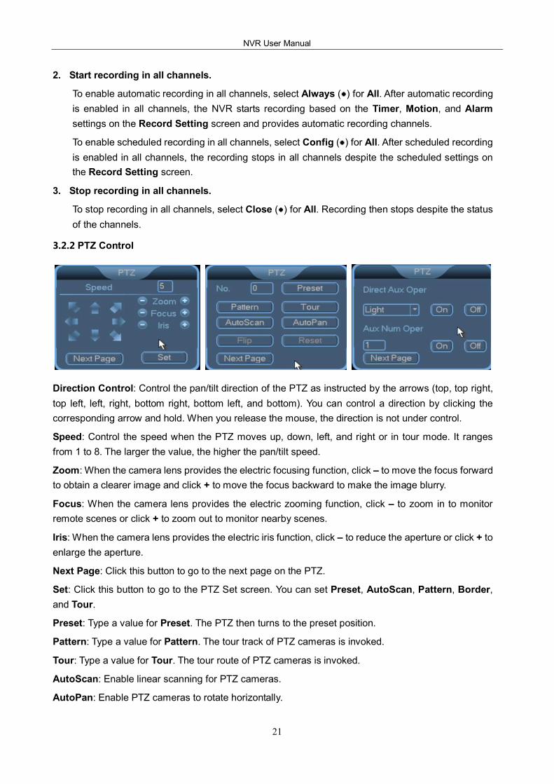
3.2.2 PTZ Control
Direction Control: Control the pan/tilt direction of the PTZ as instructed by the arrows (top, top right, top left, left, right, bottom right, bottom left, and bottom). You can control a direction by clicking the corresponding arrow and hold. When you release the mouse, the direction is not under control.
Speed: Control the speed when the PTZ moves up, down, left, and right or in tour mode. It ranges from 1 to 8. The larger the value, the higher the pan/tilt speed.
Zoom: When the camera lens provides the electric focusing function, click – to move the focus forward to obtain a clearer image and click + to move the focus backward to make the image blurry.
Focus: When the camera lens provides the electric zooming function, click – to zoom in to monitor remote scenes or click + to zoom out to monitor nearby scenes.
Iris: When the camera lens provides the electric iris function, click – to reduce the aperture or click + to enlarge the aperture.
Next Page: Click this button to go to the next page on the PTZ.
Set: Click this button to go to the PTZ Set screen. You can set Preset, AutoScan, Pattern, Border, and Tour.
Preset: Type a value for Preset. The PTZ then turns to the preset position.
Pattern: Type a value for Pattern. The tour track of PTZ cameras is invoked.
Tour: Type a value for Tour. The tour route of PTZ cameras is invoked.
AutoScan: Enable linear scanning for PTZ cameras.
AutoPan: Enable PTZ cameras to rotate horizontally.
3 System Menus
22
Flip: Enable PTZ cameras to flip.
Reset: Reset the PTZ to the poweron state.
Direct Aux Oper: Start or shut down auxiliary devices. If a camera is connected to external lights, click On to turn on the lights or click Off to turn off the lights.
Aux Num Oper: If the PTZ is connected to multiple auxiliary devices, click On to start the auxiliary devices or click Off to shut down the auxiliary devices.
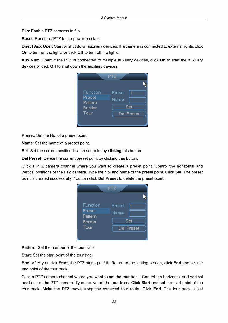
Preset: Set the No. of a preset point.
Name: Set the name of a preset point.
Set: Set the current position to a preset point by clicking this button.
Del Preset: Delete the current preset point by clicking this button.
Click a PTZ camera channel where you want to create a preset point. Control the horizontal and vertical positions of the PTZ camera. Type the No. and name of the preset point. Click Set. The preset point is created successfully. You can click Del Preset to delete the preset point.
Pattern: Set the number of the tour track.
Start: Set the start point of the tour track.
End: After you click Start, the PTZ starts pan/tilt. Return to the setting screen, click End and set the end point of the tour track.
Click a PTZ camera channel where you want to set the tour track. Control the horizontal and vertical positions of the PTZ camera. Type the No. of the tour track. Click Start and set the start point of the tour track. Make the PTZ move along the expected tour route. Click End. The tour track is set
NVR User Manual
23
successfully.
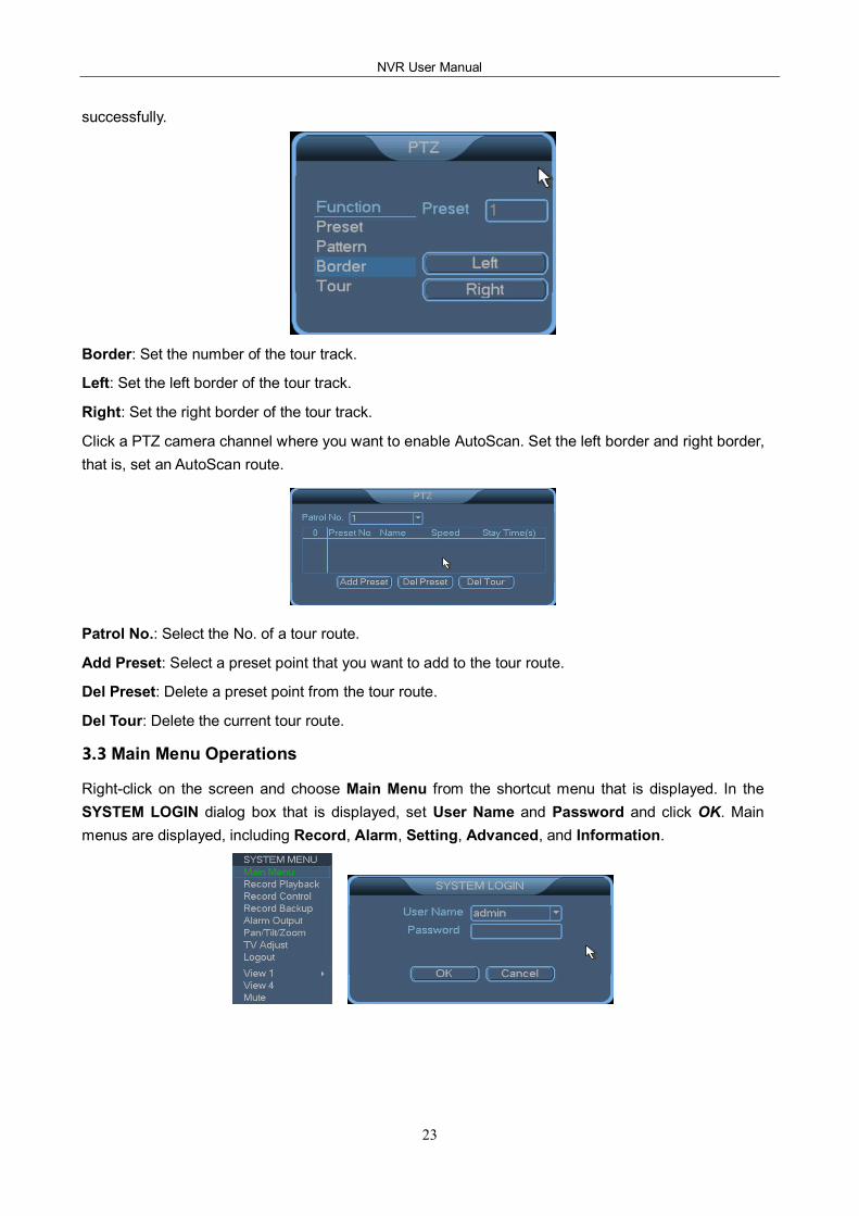
Border: Set the number of the tour track.
Left: Set the left border of the tour track.
Right: Set the right border of the tour track.
Click a PTZ camera channel where you want to enable AutoScan. Set the left border and right border, that is, set an AutoScan route.
Patrol No.: Select the No. of a tour route.
Add Preset: Select a preset point that you want to add to the tour route.
Del Preset: Delete a preset point from the tour route.
Del Tour: Delete the current tour route.
3.3 Main Menu Operations
Rightclick on the screen and choose Main Menu from the shortcut menu that is displayed. In the SYSTEM LOGIN dialog box that is displayed, set User Name and Password and click OK. Main menus are displayed, including Record, Alarm, Setting, Advanced, and Information.
3 System Menus
24
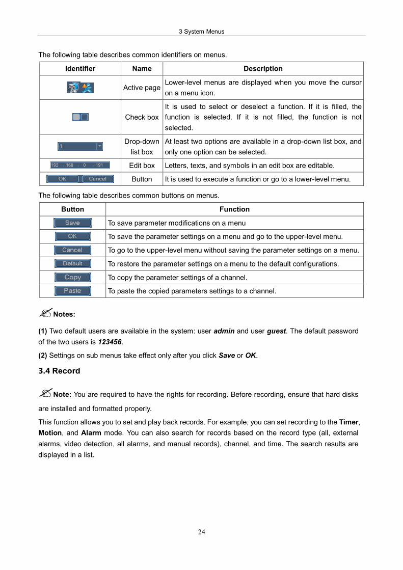
The following table describes common identifiers on menus.
Identifier Name Description
Active page Lowerlevel menus are displayed when you move the cursor on a menu icon.
Check box It is used to select or deselect a function. If it is filled, the function is selected. If it is not filled, the function is not selected.
Dropdown list box
At least two options are available in a dropdown list box, and only one option can be selected.
Edit box Letters, texts, and symbols in an edit box are editable.
Button It is used to execute a function or go to a lowerlevel menu.
The following table describes common buttons on menus.
Button Function
To save parameter modifications on a menu
To save the parameter settings on a menu and go to the upperlevel menu.
To go to the upperlevel menu without saving the parameter settings on a menu.
To restore the parameter settings on a menu to the default configurations.
To copy the parameter settings of a channel.
To paste the copied parameters settings to a channel.
?Notes:
(1) Two default users are available in the system: user admin and user guest. The default password of the two users is 123456.
(2) Settings on sub menus take effect only after you click Save or OK.
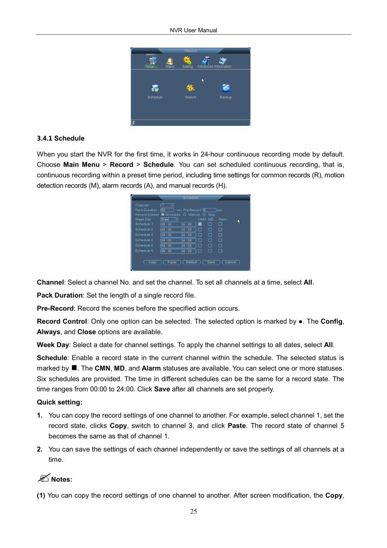
3.4 Record
?Note: You are required to have the rights for recording. Before recording, ensure that hard disks
are installed and formatted properly.
This function allows you to set and play back records. For example, you can set recording to the Timer, Motion, and Alarm mode. You can also search for records based on the record type (all, external alarms, video detection, all alarms, and manual records), channel, and time. The search results are displayed in a list.
NVR User Manual
25
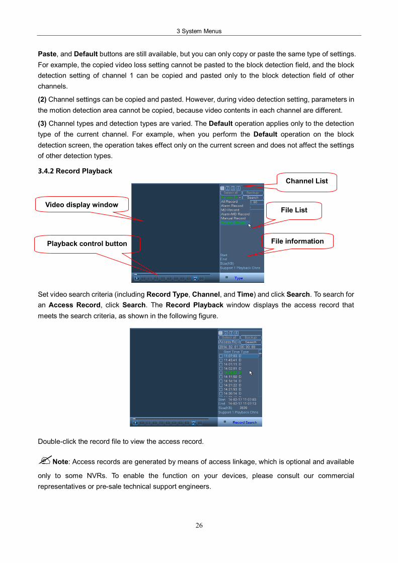
3.4.1 Schedule
When you start the NVR for the first time, it works in 24hour continuous recording mode by default. Choose Main Menu > Record > Schedule. You can set scheduled continuous recording, that is, continuous recording within a preset time period, including time settings for common records (R), motion detection records (M), alarm records (A), and manual records (H).
Channel: Select a channel No. and set the channel. To set all channels at a time, select All.
Pack Duration: Set the length of a single record file.
PreRecord: Record the scenes before the specified action occurs.
Record Control: Only one option can be selected. The selected option is marked by . The Config, Always, and Close options are available.
Week Day: Select a date for channel settings. To apply the channel settings to all dates, select All.
Schedule: Enable a record state in the current channel within the schedule. The selected status is marked by . The CMN, MD, and Alarm statuses are available. You can select one or more statuses. Six schedules are provided. The time in different schedules can be the same for a record state. The time ranges from 00:00 to 24:00. Click Save after all channels are set properly.
Quick setting:
1. You can copy the record settings of one channel to another. For example, select channel 1, set the record state, clicks Copy, switch to channel 3, and click Paste. The record state of channel 5 becomes the same as that of channel 1.
2. You can save the settings of each channel independently or save the settings of all channels at a time.
?Notes:
(1) You can copy the record settings of one channel to another. After screen modification, the Copy,
3 System Menus
26
Paste, and Default buttons are still available, but you can only copy or paste the same type of settings. For example, the copied video loss setting cannot be pasted to the block detection field, and the block detection setting of channel 1 can be copied and pasted only to the block detection field of other channels.
(2) Channel settings can be copied and pasted. However, during video detection setting, parameters in the motion detection area cannot be copied, because video contents in each channel are different.
(3) Channel types and detection types are varied. The Default operation applies only to the detection type of the current channel. For example, when you perform the Default operation on the block detection screen, the operation takes effect only on the current screen and does not affect the settings of other detection types.
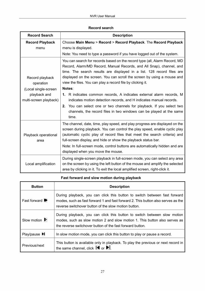
3.4.2 Record Playback
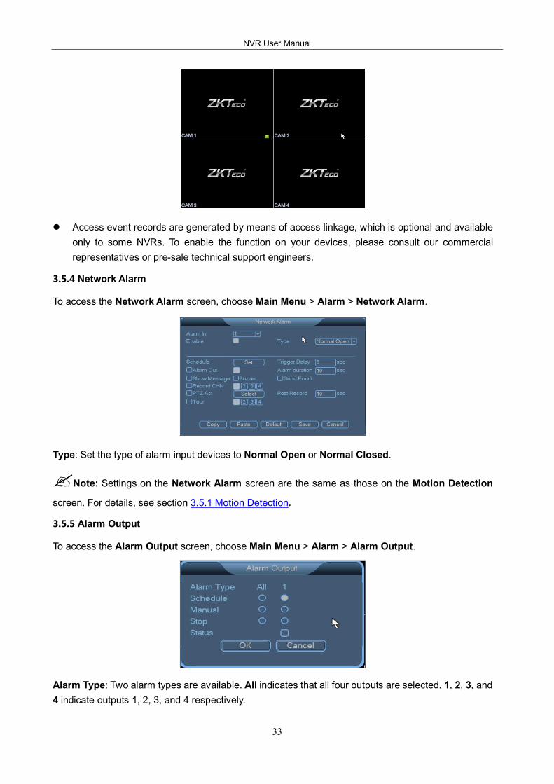
Set video search criteria (including Record Type, Channel, and Time) and click Search. To search for an Access Record, click Search. The Record Playback window displays the access record that meets the search criteria, as shown in the following figure.
Doubleclick the record file to view the access record.
?Note: Access records are generated by means of access linkage, which is optional and available
only to some NVRs. To enable the function on your devices, please consult our commercial representatives or presale technical support engineers.
Video display window
Playback control button
Channel List
File List
File information
NVR User Manual
27
Record search
Record Search Description
Record Playback menu
Choose Main Menu > Record > Record Playback. The Record Playback menu is displayed. Note: You need to type a password if you have logged out of the system.
Record playback operation
(Local singlescreen playback and
multiscreen playback)
You can search for records based on the record type (all, Alarm Record, MD Record, Alarm/MD Record, Manual Records, and All Snap), channel, and time. The search results are displayed in a list. 128 record files are displayed on the screen. You can scroll the screen by using a mouse and view the files. You can play a record file by clicking it. Notes: 1. R indicates common records, A indicates external alarm records, M
indicates motion detection records, and H indicates manual records. 2. You can select one or two channels for playback. If you select two
channels, the record files in two windows can be played at the same time.
Playback operational area
The channel, date, time, play speed, and play progress are displayed on the screen during playback. You can control the play speed, enable cyclic play (automatic cyclic play of record files that meet the search criteria) and fullscreen display, and hide or show the playback status bar. Note: In fullscreen mode, control buttons are automatically hidden and are displayed when you move the mouse.
Local amplification During singlescreen playback in fullscreen mode, you can select any area on the screen by using the left button of the mouse and amplify the selected area by clicking in it. To exit the local amplified screen, rightclick it.
Fast forward and slow motion during playback
Button Description
Fast forward During playback, you can click this button to switch between fast forward modes, such as fast forward 1 and fast forward 2. This button also serves as the reverse switchover button of the slow motion button.
Slow motion During playback, you can click this button to switch between slow motion modes, such as slow motion 2 and slow motion 1. This button also serves as the reverse switchover button of the fast forward button.
Play/pause In slow motion mode, you can click this button to play or pause a record.
Previous/next This button is available only in playback. To play the previous or next record in the same channel, click or .
3 System Menus
28
Reverse play and framebyframe playback
Button Description Remarks
Reverse play (playback control button )
When you click on the playback control bar during normal play of a record file, the record file starts to be played in reverse. When you click again, the reverse play stops.
Manual framebyframe playback
When you pause a record file, you can press the right arrow key to enable framebyframe playback and press the down arrow key to play back the I frame.
In reverse play or framebyframe play mode, you can click to switch to the normal playback status.
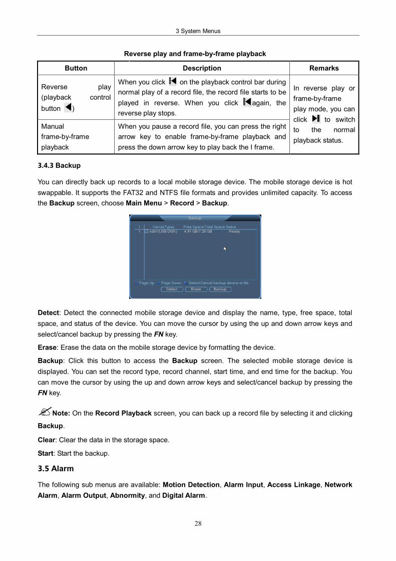
3.4.3 Backup
You can directly back up records to a local mobile storage device. The mobile storage device is hot swappable. It supports the FAT32 and NTFS file formats and provides unlimited capacity. To access the Backup screen, choose Main Menu > Record > Backup.
Detect: Detect the connected mobile storage device and display the name, type, free space, total space, and status of the device. You can move the cursor by using the up and down arrow keys and select/cancel backup by pressing the FN key.
Erase: Erase the data on the mobile storage device by formatting the device.
Backup: Click this button to access the Backup screen. The selected mobile storage device is displayed. You can set the record type, record channel, start time, and end time for the backup. You can move the cursor by using the up and down arrow keys and select/cancel backup by pressing the FN key.
?Note: On the Record Playback screen, you can back up a record file by selecting it and clicking
Backup.
Clear: Clear the data in the storage space.
Start: Start the backup.
3.5 Alarm
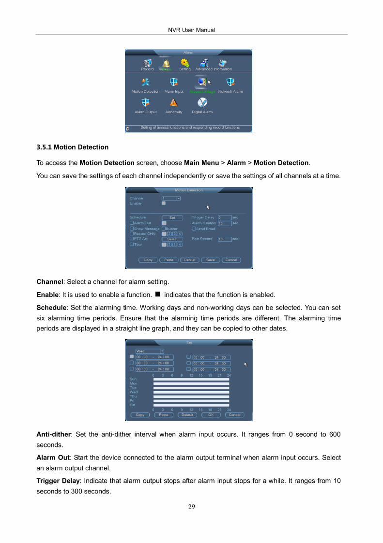
The following sub menus are available: Motion Detection, Alarm Input, Access Linkage, Network Alarm, Alarm Output, Abnormity, and Digital Alarm.
NVR User Manual
29
3.5.1 Motion Detection
To access the Motion Detection screen, choose Main Menu > Alarm > Motion Detection.
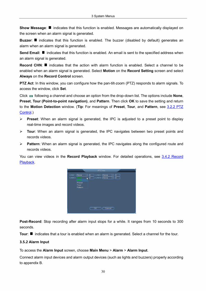
You can save the settings of each channel independently or save the settings of all channels at a time.
Channel: Select a channel for alarm setting.
Enable: It is used to enable a function. indicates that the function is enabled.
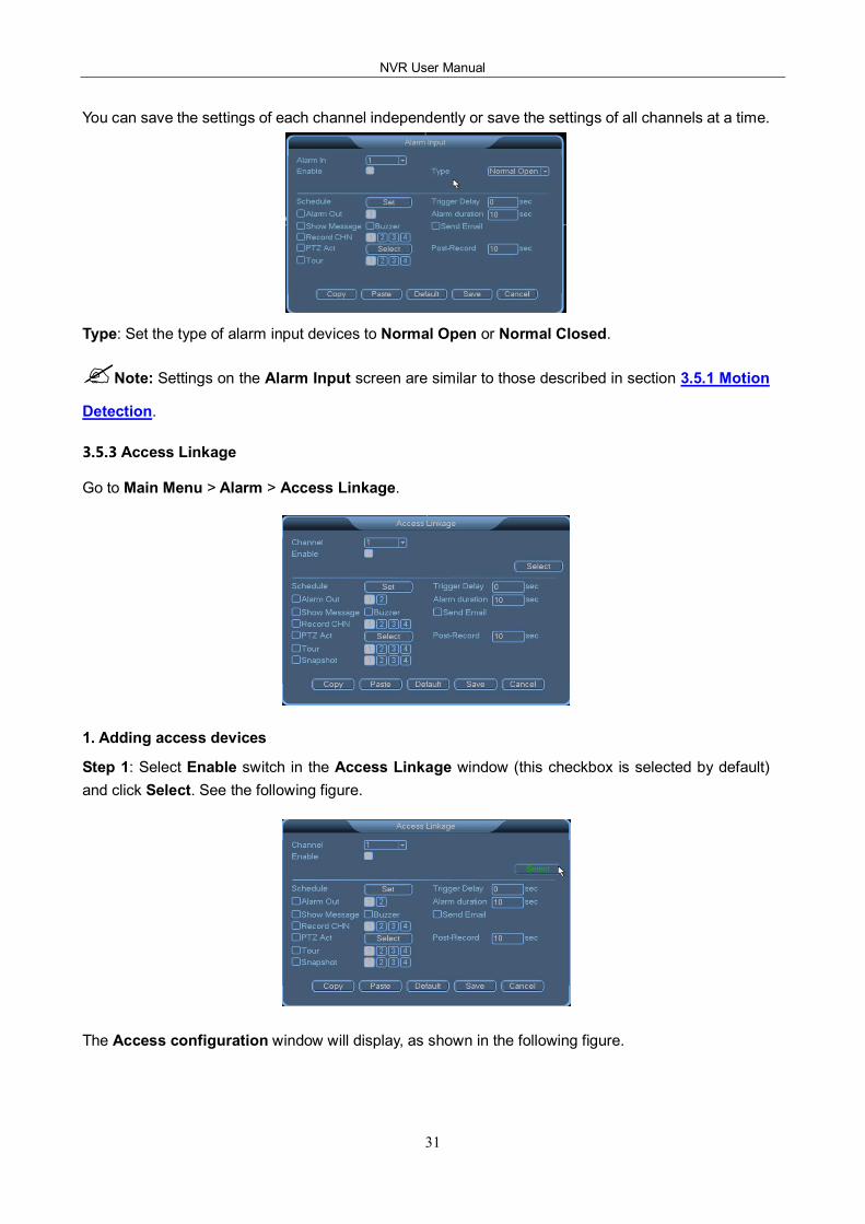
Schedule: Set the alarming time. Working days and nonworking days can be selected. You can set six alarming time periods. Ensure that the alarming time periods are different. The alarming time periods are displayed in a straight line graph, and they can be copied to other dates.
Antidither: Set the antidither interval when alarm input occurs. It ranges from 0 second to 600 seconds.
Alarm Out: Start the device connected to the alarm output terminal when alarm input occurs. Select an alarm output channel.
Trigger Delay: Indicate that alarm output stops after alarm input stops for a while. It ranges from 10 seconds to 300 seconds.
3 System Menus
30
Show Message: indicates that this function is enabled. Messages are automatically displayed on the screen when an alarm signal is generated.
Buzzer: indicates that this function is enabled. The buzzer (disabled by default) generates an alarm when an alarm signal is generated.
Send Email: indicates that this function is enabled. An email is sent to the specified address when an alarm signal is generated.
Record CHN: indicates that the action with alarm function is enabled. Select a channel to be enabled when an alarm signal is generated. Select Motion on the Record Setting screen and select Always on the Record Control screen.
PTZ Act: In this window, you can configure how the pantiltzoom (PTZ) responds to alarm signals. To access the window, click Set.
Click following a channel and choose an option from the dropdown list. The options include None, Preset, Tour (Pointtopoint navigation), and Pattern. Then click OK to save the setting and return to the Motion Detection window. (Tip: For meanings of Preset, Tour, and Pattern, see 3.2.2 PTZ Control.)
Ø Preset: When an alarm signal is generated, the IPC is adjusted to a preset point to display realtime images and record videos.
Ø Tour: When an alarm signal is generated, the IPC navigates between two preset points and records videos.
Ø Pattern: When an alarm signal is generated, the IPC navigates along the configured route and records videos.
You can view videos in the Record Playback window. For detailed operations, see 3.4.2 Record Playback.
PostRecord: Stop recording after alarm input stops for a while. It ranges from 10 seconds to 300 seconds.
Tour: indicates that a tour is enabled when an alarm is generated. Select a channel for the tour.
3.5.2 Alarm Input
To access the Alarm Input screen, choose Main Menu > Alarm > Alarm Input.
Connect alarm input devices and alarm output devices (such as lights and buzzers) properly according to appendix B.
NVR User Manual
31
You can save the settings of each channel independently or save the settings of all channels at a time.
Type: Set the type of alarm input devices to Normal Open or Normal Closed.
?Note: Settings on the Alarm Input screen are similar to those described in section 3.5.1 Motion
Detection.
3.5.3 Access Linkage
Go to Main Menu > Alarm > Access Linkage.
1. Adding access devices
Step 1: Select Enable switch in the Access Linkage window (this checkbox is selected by default) and click Select. See the following figure.
The Access configuration window will display, as shown in the following figure.
3 System Menus
32
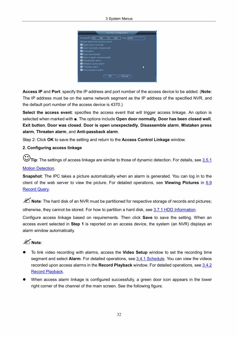
Access IP and Port: specify the IP address and port number of the access device to be added. (Note: The IP address must be on the same network segment as the IP address of the specified NVR, and the default port number of the access device is 4370.)
Select the access event: specifies the access event that will trigger access linkage. An option is selected when marked with . The options include Open door normally, Door has been closed well, Exit button, Door was closed, Door is open unexpectedly, Disassemble alarm, Mistaken press alarm, Threaten alarm, and Antipassback alarm.
Step 2: Click OK to save the setting and return to the Access Control Linkage window.
2. Configuring access linkage
Tip: The settings of access linkage are similar to those of dynamic detection. For details, see 3.5.1
Motion Detection.
Snapshot: The IPC takes a picture automatically when an alarm is generated. You can log in to the client of the web server to view the picture. For detailed operations, see Viewing Pictures in 6.9 Record Query.
?Note: The hard disk of an NVR must be partitioned for respective storage of records and pictures;
otherwise, they cannot be stored. For how to partition a hard disk, see 3.7.1 HDD Information.
Configure access linkage based on requirements. Then click Save to save the setting. When an access event selected in Step 1 is reported on an access device, the system (an NVR) displays an alarm window automatically.
?Note:
l To link video recording with alarms, access the Video Setup window to set the recording time segment and select Alarm. For detailed operations, see 3.4.1 Schedule. You can view the videos recorded upon access alarms in the Record Playback window. For detailed operations, see 3.4.2 Record Playback.
l When access alarm linkage is configured successfully, a green door icon appears in the lower right corner of the channel of the main screen. See the following figure.
NVR User Manual
33
l Access event records are generated by means of access linkage, which is optional and available only to some NVRs. To enable the function on your devices, please consult our commercial representatives or presale technical support engineers.
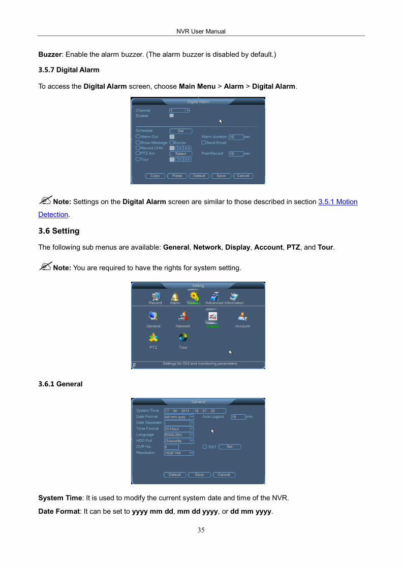
3.5.4 Network Alarm
To access the Network Alarm screen, choose Main Menu > Alarm > Network Alarm.
Type: Set the type of alarm input devices to Normal Open or Normal Closed.
?Note: Settings on the Network Alarm screen are the same as those on the Motion Detection
screen. For details, see section 3.5.1 Motion Detection.
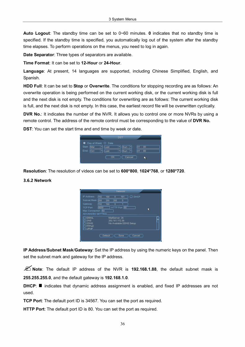
3.5.5 Alarm Output
To access the Alarm Output screen, choose Main Menu > Alarm > Alarm Output.
Alarm Type: Two alarm types are available. All indicates that all four outputs are selected. 1, 2, 3, and 4 indicate outputs 1, 2, 3, and 4 respectively.

3 System Menus
34
Config: indicates that the option is selected. If is marked for All, all four alarm outputs are configured. If is marked for 1, 2, 3, or 4, alarm output 1, 2, 3, or 4 is configured.
Always: indicates that the option is selected. If is marked for All, all four alarm outputs are always enabled. If is marked for 1, 2, 3, or 4, alarm output 1, 2, 3, or 4 is always enabled.
Close: This option is used to disable alarm outputs.
Status: This option is used to display the alarm output status of the current device.
3.5.6 Abnormity
You can set the event type and associated actions on the Abnormity screen. Select Enable. When an abnormity occurs, the system automatically generates alarms, displays messages on the screen, and sends emails. To access the Abnormity screen, choose Main Menu > Alarm > Abnormity.
Event Type: Abnormity event types include No hard disk, Disk Error, Disk No Space, Network Disconnection, and IP conflicted.
No hard disk: No hard disk is installed on the NVR, or the hardware system is faulty and fails to detect hard disks.
Disk Error: Hard disks are faulty, or the system fails to detect hard disks.
Disk No Space: No storage space is available on the hard disks. (When Event Type is set to Disk No Space, the system prompts you to set the lower limit, that is, the percentage of the free disk space.)
Network Disconnection: The NVR is disconnected from the network, or network connection errors occur.
IP Conflicted: The NVR has a fixed IP address, which is the same as that of another device on the network.
Enable: It is used to enable a function. indicates that the function is enabled.
Alarm Out: Start the device connected to the alarm output terminal when an abnormity occurs. Select one or more alarm output channels.
Show Message: indicates that this function is enabled. Messages are automatically displayed on the screen when an alarm signal is generated.
Send Email: indicates that this function is enabled. An email is sent to the specified address when an alarm signal is generated.
Alarm duration: set the alarm output delay. It ranges from 10 seconds to 300 seconds.
NVR User Manual
35
Buzzer: Enable the alarm buzzer. (The alarm buzzer is disabled by default.)
3.5.7 Digital Alarm
To access the Digital Alarm screen, choose Main Menu > Alarm > Digital Alarm.
?Note: Settings on the Digital Alarm screen are similar to those described in section 3.5.1 Motion
Detection.
3.6 Setting
The following sub menus are available: General, Network, Display, Account, PTZ, and Tour.
?Note: You are required to have the rights for system setting.
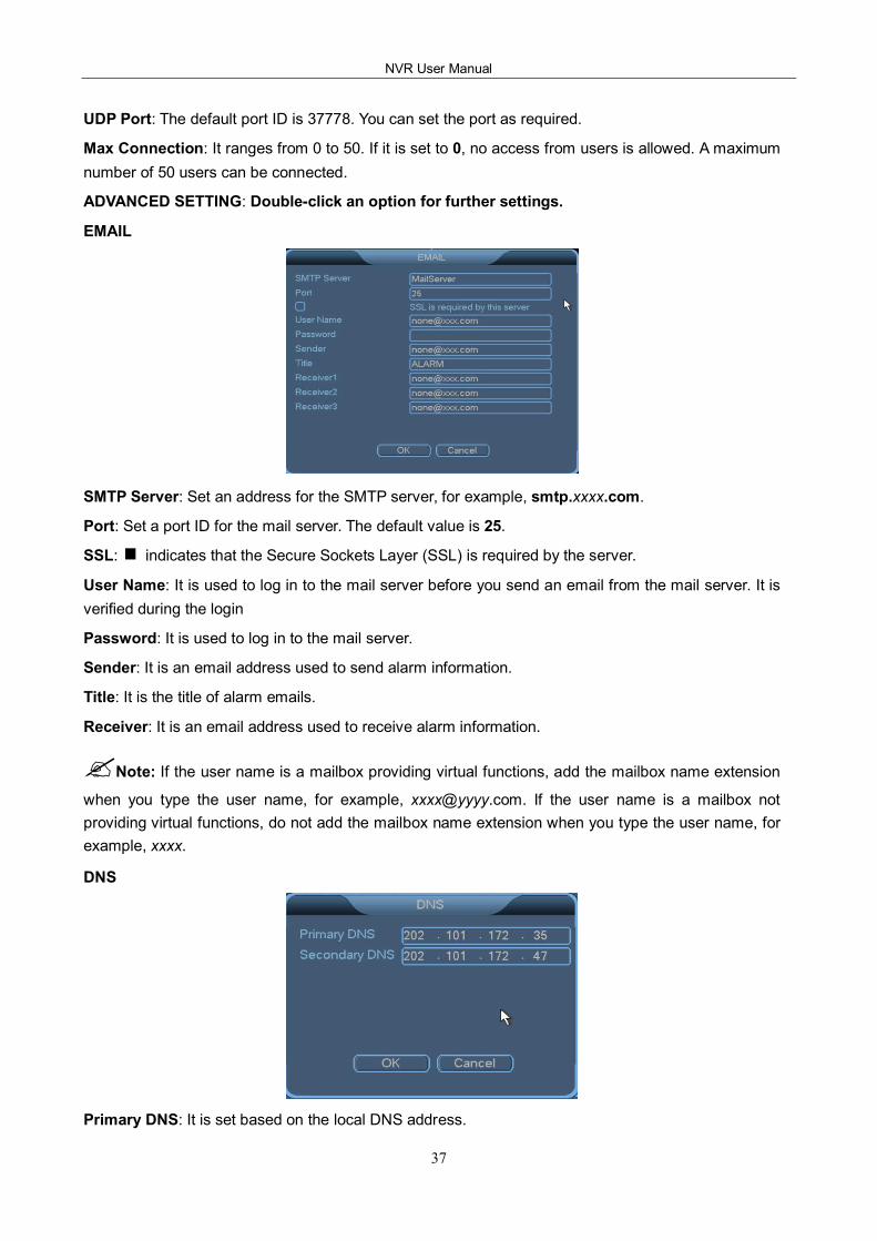
3.6.1 General
System Time: It is used to modify the current system date and time of the NVR.
Date Format: It can be set to yyyy mm dd, mm dd yyyy, or dd mm yyyy.
3 System Menus
36
Auto Logout: The standby time can be set to 0~60 minutes. 0 indicates that no standby time is specified. If the standby time is specified, you automatically log out of the system after the standby time elapses. To perform operations on the menus, you need to log in again.
Date Separator: Three types of separators are available.
Time Format: It can be set to 12Hour or 24Hour.
Language: At present, 14 languages are supported, including Chinese Simplified, English, and Spanish.
HDD Full: It can be set to Stop or Overwrite. The conditions for stopping recording are as follows: An overwrite operation is being performed on the current working disk, or the current working disk is full and the next disk is not empty. The conditions for overwriting are as follows: The current working disk is full, and the next disk is not empty. In this case, the earliest record file will be overwritten cyclically.
DVR No.: It indicates the number of the NVR. It allows you to control one or more NVRs by using a remote control. The address of the remote control must be corresponding to the value of DVR No.
DST: You can set the start time and end time by week or date.
Resolution: The resolution of videos can be set to 600*800, 1024*768, or 1280*720.
3.6.2 Network
IP Address/Subnet Mask/Gateway: Set the IP address by using the numeric keys on the panel. Then set the subnet mark and gateway for the IP address.
?Note: The default IP address of the NVR is 192.168.1.88, the default subnet mask is
255.255.255.0, and the default gateway is 192.168.1.0.
DHCP: indicates that dynamic address assignment is enabled, and fixed IP addresses are not used.
TCP Port: The default port ID is 34567. You can set the port as required.
HTTP Port: The default port ID is 80. You can set the port as required.
NVR User Manual
37
UDP Port: The default port ID is 37778. You can set the port as required.
Max Connection: It ranges from 0 to 50. If it is set to 0, no access from users is allowed. A maximum number of 50 users can be connected.
ADVANCED SETTING: Doubleclick an option for further settings.
SMTP Server: Set an address for the SMTP server, for example, smtp.xxxx.com.
Port: Set a port ID for the mail server. The default value is 25.
SSL: indicates that the Secure Sockets Layer (SSL) is required by the server.
User Name: It is used to log in to the mail server before you send an email from the mail server. It is verified during the login
Password: It is used to log in to the mail server.
Sender: It is an email address used to send alarm information.
Title: It is the title of alarm emails.
Receiver: It is an email address used to receive alarm information.
?Note: If the user name is a mailbox providing virtual functions, add the mailbox name extension
when you type the user name, for example, [email protected]. If the user name is a mailbox not providing virtual functions, do not add the mailbox name extension when you type the user name, for example, xxxx.
DNS
Primary DNS: It is set based on the local DNS address.
3 System Menus
38
Secondary DNS: It is set based on the local DNS address.
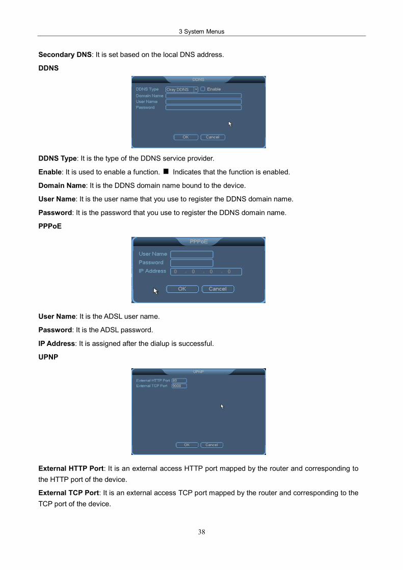
DDNS
DDNS Type: It is the type of the DDNS service provider.
Enable: It is used to enable a function. Indicates that the function is enabled.
Domain Name: It is the DDNS domain name bound to the device.
User Name: It is the user name that you use to register the DDNS domain name.
Password: It is the password that you use to register the DDNS domain name.
PPPoE
User Name: It is the ADSL user name.
Password: It is the ADSL password.
IP Address: It is assigned after the dialup is successful.
UPNP
External HTTP Port: It is an external access HTTP port mapped by the router and corresponding to the HTTP port of the device.
External TCP Port: It is an external access TCP port mapped by the router and corresponding to the TCP port of the device.
NVR User Manual
39
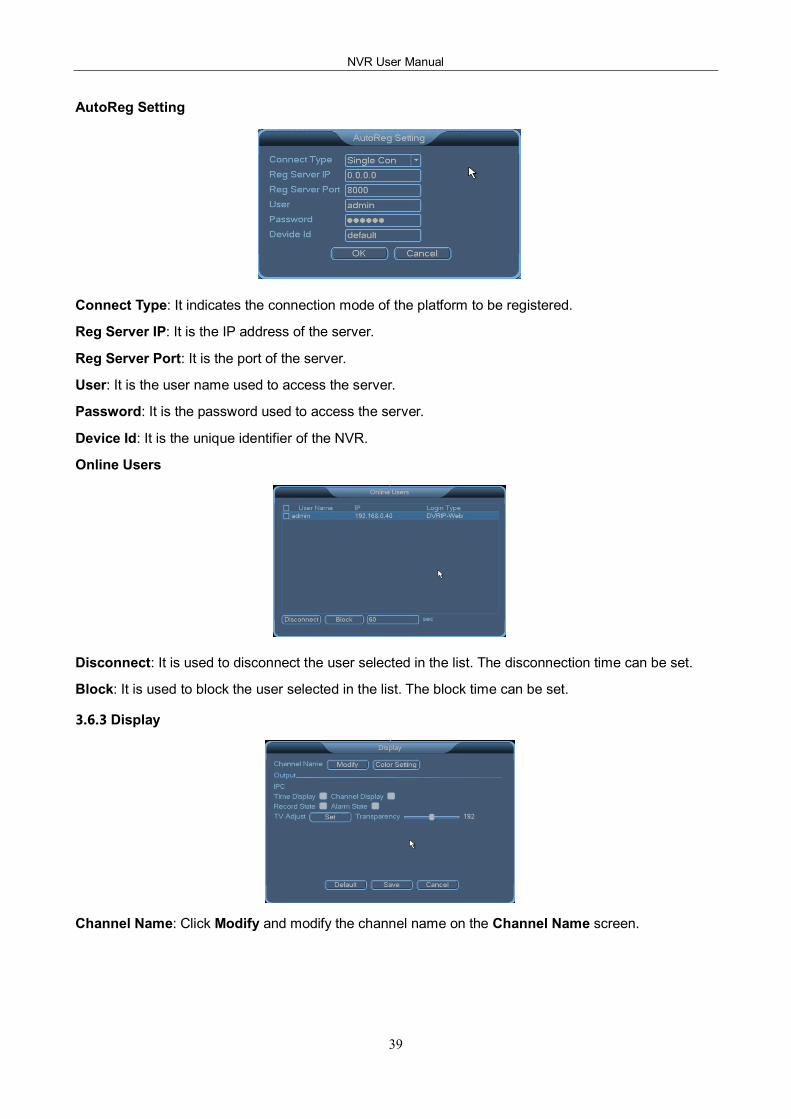
AutoReg Setting
Connect Type: It indicates the connection mode of the platform to be registered.
Reg Server IP: It is the IP address of the server.
Reg Server Port: It is the port of the server.
User: It is the user name used to access the server.
Password: It is the password used to access the server.
Device Id: It is the unique identifier of the NVR.
Online Users
Disconnect: It is used to disconnect the user selected in the list. The disconnection time can be set.
Block: It is used to block the user selected in the list. The block time can be set.
3.6.3 Display
Channel Name: Click Modify and modify the channel name on the Channel Name screen.
3 System Menus
40
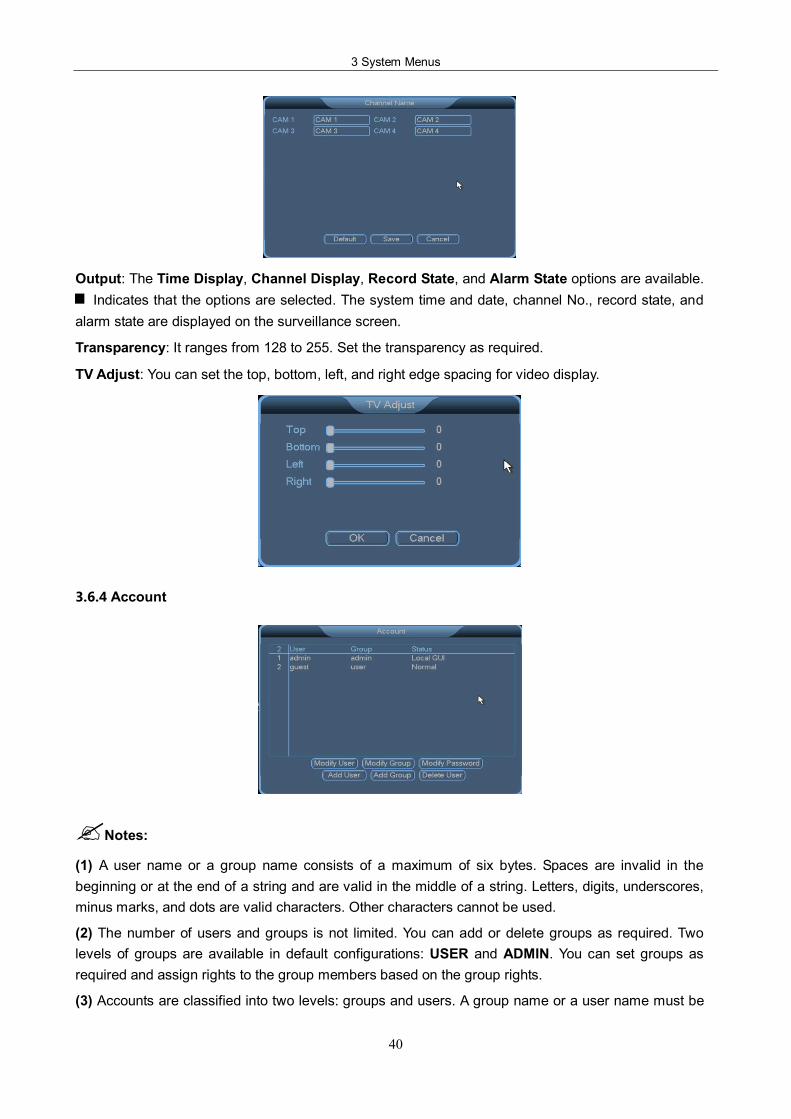
Output: The Time Display, Channel Display, Record State, and Alarm State options are available. Indicates that the options are selected. The system time and date, channel No., record state, and
alarm state are displayed on the surveillance screen.
Transparency: It ranges from 128 to 255. Set the transparency as required.
TV Adjust: You can set the top, bottom, left, and right edge spacing for video display.
3.6.4 Account
?Notes:
(1) A user name or a group name consists of a maximum of six bytes. Spaces are invalid in the beginning or at the end of a string and are valid in the middle of a string. Letters, digits, underscores, minus marks, and dots are valid characters. Other characters cannot be used.
(2) The number of users and groups is not limited. You can add or delete groups as required. Two levels of groups are available in default configurations: USER and ADMIN. You can set groups as required and assign rights to the group members based on the group rights.
(3) Accounts are classified into two levels: groups and users. A group name or a user name must be
NVR User Manual
41
unique. A user must be added to and can be added only to one group.
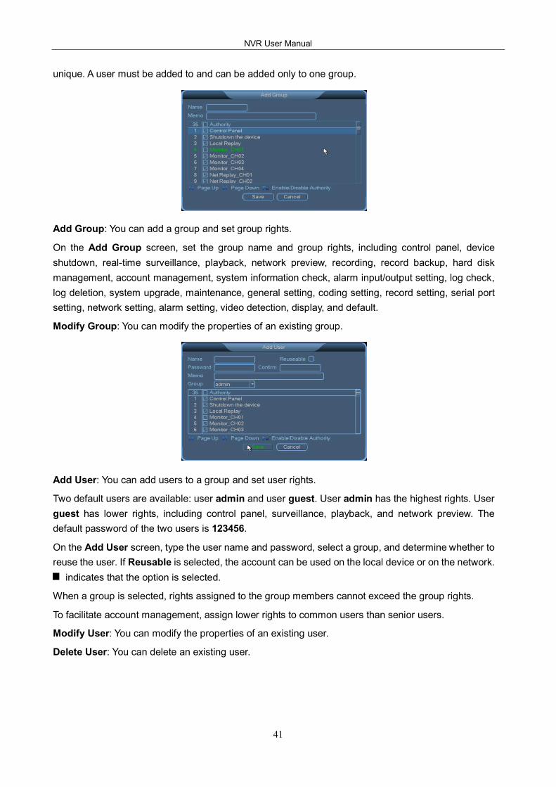
Add Group: You can add a group and set group rights.
On the Add Group screen, set the group name and group rights, including control panel, device shutdown, realtime surveillance, playback, network preview, recording, record backup, hard disk management, account management, system information check, alarm input/output setting, log check, log deletion, system upgrade, maintenance, general setting, coding setting, record setting, serial port setting, network setting, alarm setting, video detection, display, and default.
Modify Group: You can modify the properties of an existing group.
Add User: You can add users to a group and set user rights.
Two default users are available: user admin and user guest. User admin has the highest rights. User guest has lower rights, including control panel, surveillance, playback, and network preview. The default password of the two users is 123456.
On the Add User screen, type the user name and password, select a group, and determine whether to reuse the user. If Reusable is selected, the account can be used on the local device or on the network.
indicates that the option is selected.
When a group is selected, rights assigned to the group members cannot exceed the group rights.
To facilitate account management, assign lower rights to common users than senior users.
Modify User: You can modify the properties of an existing user.
Delete User: You can delete an existing user.
3 System Menus
42
Modify Password: You can modify the password of an existing user. Access the Modify Password screen, select a user name, type a new password in the New Password text box, confirm it, and click Save. A password consists of a maximum of six characters. Spaces are invalid in the beginning or at the end of a password and are valid in the middle of a password. User admin can modify the passwords of other users.
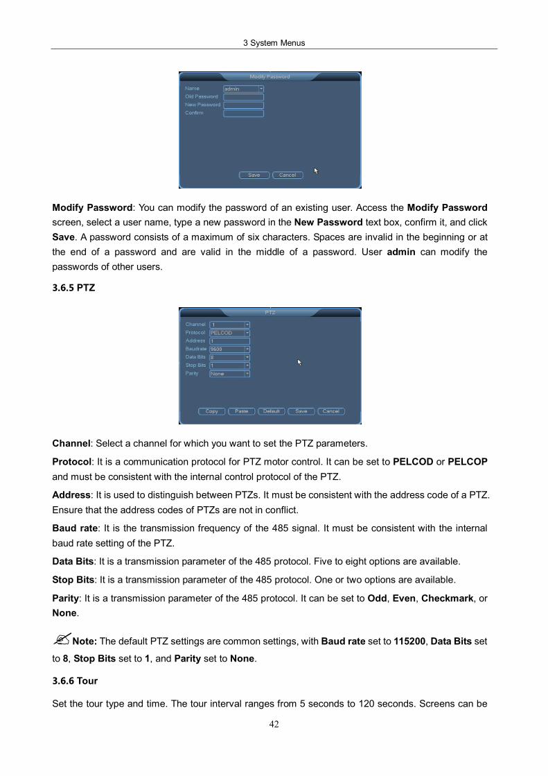
3.6.5 PTZ
Channel: Select a channel for which you want to set the PTZ parameters.
Protocol: It is a communication protocol for PTZ motor control. It can be set to PELCOD or PELCOP and must be consistent with the internal control protocol of the PTZ.
Address: It is used to distinguish between PTZs. It must be consistent with the address code of a PTZ. Ensure that the address codes of PTZs are not in conflict.
Baud rate: It is the transmission frequency of the 485 signal. It must be consistent with the internal baud rate setting of the PTZ.
Data Bits: It is a transmission parameter of the 485 protocol. Five to eight options are available.
Stop Bits: It is a transmission parameter of the 485 protocol. One or two options are available.
Parity: It is a transmission parameter of the 485 protocol. It can be set to Odd, Even, Checkmark, or None.
?Note: The default PTZ settings are common settings, with Baud rate set to 115200, Data Bits set
to 8, Stop Bits set to 1, and Parity set to None.
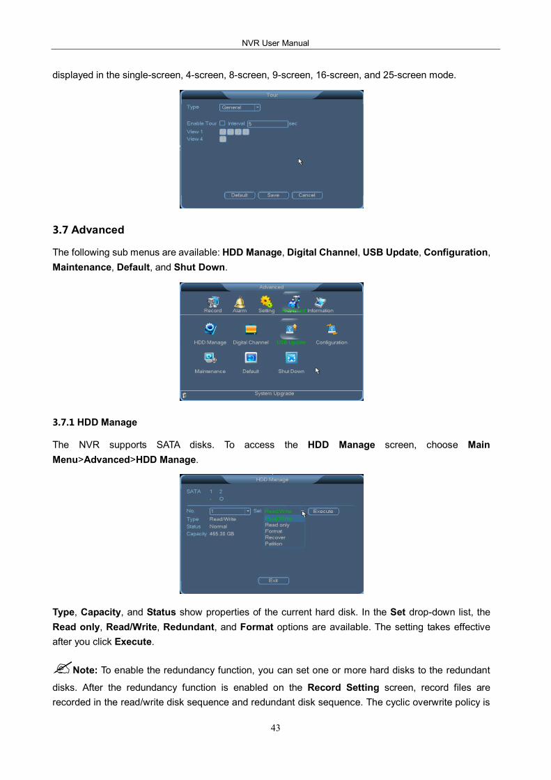
3.6.6 Tour
Set the tour type and time. The tour interval ranges from 5 seconds to 120 seconds. Screens can be
NVR User Manual
43
displayed in the singlescreen, 4screen, 8screen, 9screen, 16screen, and 25screen mode.
3.7 Advanced
The following sub menus are available: HDD Manage, Digital Channel, USB Update, Configuration, Maintenance, Default, and Shut Down.
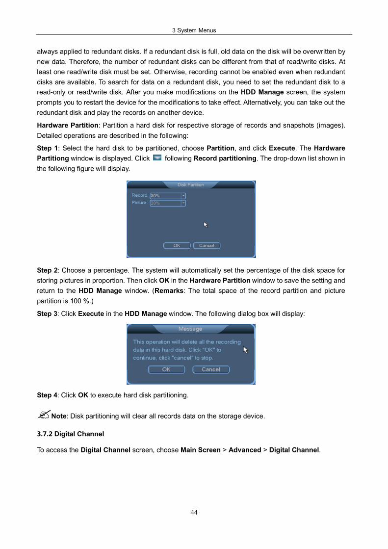
3.7.1 HDD Manage
The NVR supports SATA disks. To access the HDD Manage screen, choose Main Menu>Advanced>HDD Manage.
Type, Capacity, and Status show properties of the current hard disk. In the Set dropdown list, the Read only, Read/Write, Redundant, and Format options are available. The setting takes effective after you click Execute.
?Note: To enable the redundancy function, you can set one or more hard disks to the redundant
disks. After the redundancy function is enabled on the Record Setting screen, record files are recorded in the read/write disk sequence and redundant disk sequence. The cyclic overwrite policy is
3 System Menus
44
always applied to redundant disks. If a redundant disk is full, old data on the disk will be overwritten by new data. Therefore, the number of redundant disks can be different from that of read/write disks. At least one read/write disk must be set. Otherwise, recording cannot be enabled even when redundant disks are available. To search for data on a redundant disk, you need to set the redundant disk to a readonly or read/write disk. After you make modifications on the HDD Manage screen, the system prompts you to restart the device for the modifications to take effect. Alternatively, you can take out the redundant disk and play the records on another device.
Hardware Partition: Partition a hard disk for respective storage of records and snapshots (images). Detailed operations are described in the following:
Step 1: Select the hard disk to be partitioned, choose Partition, and click Execute. The Hardware Partitiong window is displayed. Click following Record partitioning. The dropdown list shown in the following figure will display.
Step 2: Choose a percentage. The system will automatically set the percentage of the disk space for storing pictures in proportion. Then click OK in the Hardware Partition window to save the setting and return to the HDD Manage window. (Remarks: The total space of the record partition and picture partition is 100 %.)
Step 3: Click Execute in the HDD Manage window. The following dialog box will display:
Step 4: Click OK to execute hard disk partitioning.
?Note: Disk partitioning will clear all records data on the storage device.
3.7.2 Digital Channel
To access the Digital Channel screen, choose Main Screen > Advanced > Digital Channel.
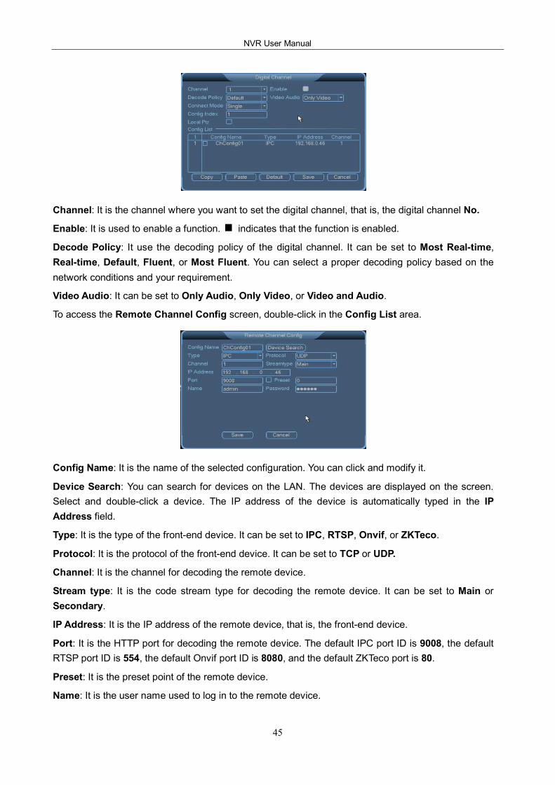
NVR User Manual
45
Channel: It is the channel where you want to set the digital channel, that is, the digital channel No.
Enable: It is used to enable a function. indicates that the function is enabled.
Decode Policy: It use the decoding policy of the digital channel. It can be set to Most Realtime, Realtime, Default, Fluent, or Most Fluent. You can select a proper decoding policy based on the network conditions and your requirement.
Video Audio: It can be set to Only Audio, Only Video, or Video and Audio.
To access the Remote Channel Config screen, doubleclick in the Config List area.
Config Name: It is the name of the selected configuration. You can click and modify it.
Device Search: You can search for devices on the LAN. The devices are displayed on the screen. Select and doubleclick a device. The IP address of the device is automatically typed in the IP Address field.
Type: It is the type of the frontend device. It can be set to IPC, RTSP, Onvif, or ZKTeco.
Protocol: It is the protocol of the frontend device. It can be set to TCP or UDP.
Channel: It is the channel for decoding the remote device.
Stream type: It is the code stream type for decoding the remote device. It can be set to Main or Secondary.
IP Address: It is the IP address of the remote device, that is, the frontend device.
Port: It is the HTTP port for decoding the remote device. The default IPC port ID is 9008, the default RTSP port ID is 554, the default Onvif port ID is 8080, and the default ZKTeco port is 80.
Preset: It is the preset point of the remote device.
Name: It is the user name used to log in to the remote device.
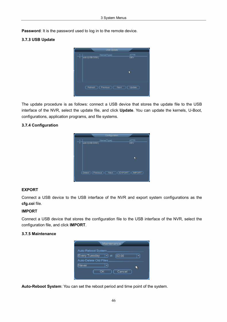
3 System Menus
46
Password: It is the password used to log in to the remote device.
3.7.3 USB Update
The update procedure is as follows: connect a USB device that stores the update file to the USB interface of the NVR, select the update file, and click Update. You can update the kernels, UBoot, configurations, application programs, and file systems.
3.7.4 Configuration
EXPORT
Connect a USB device to the USB interface of the NVR and export system configurations as the cfg.coi file.
IMPORT
Connect a USB device that stores the configuration file to the USB interface of the NVR, select the configuration file, and click IMPORT.
3.7.5 Maintenance
AutoReboot System: You can set the reboot period and time point of the system.
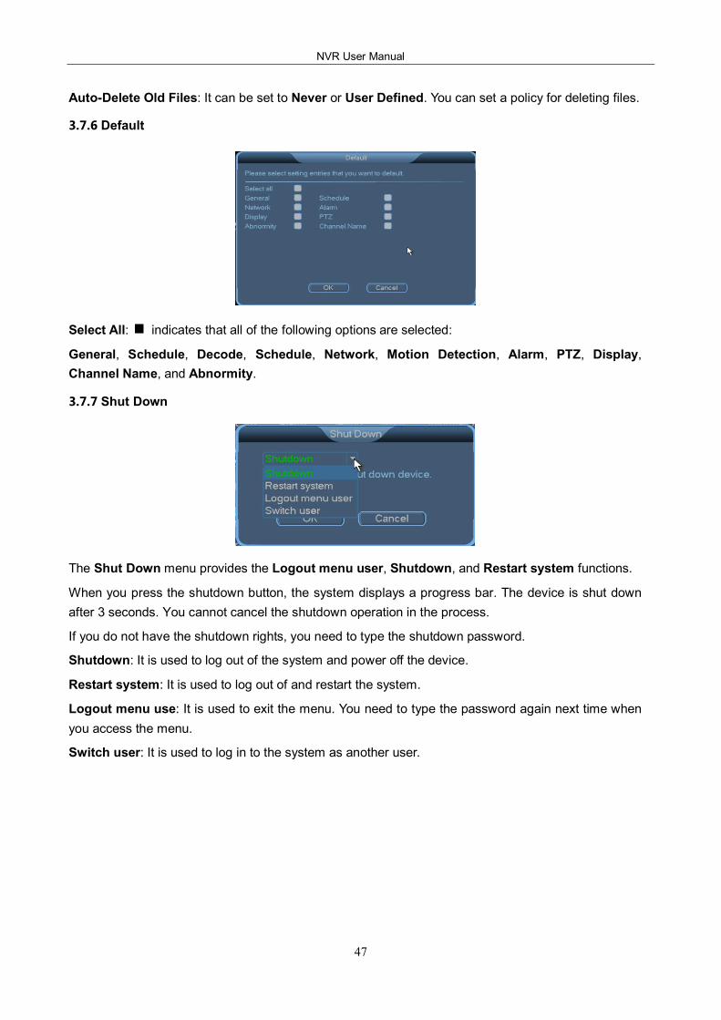
NVR User Manual
47
AutoDelete Old Files: It can be set to Never or User Defined. You can set a policy for deleting files.
3.7.6 Default
Select All: indicates that all of the following options are selected:
General, Schedule, Decode, Schedule, Network, Motion Detection, Alarm, PTZ, Display, Channel Name, and Abnormity.
3.7.7 Shut Down
The Shut Down menu provides the Logout menu user, Shutdown, and Restart system functions.
When you press the shutdown button, the system displays a progress bar. The device is shut down after 3 seconds. You cannot cancel the shutdown operation in the process.
If you do not have the shutdown rights, you need to type the shutdown password.
Shutdown: It is used to log out of the system and power off the device.
Restart system: It is used to log out of and restart the system.
Logout menu use: It is used to exit the menu. You need to type the password again next time when you access the menu.
Switch user: It is used to log in to the system as another user.
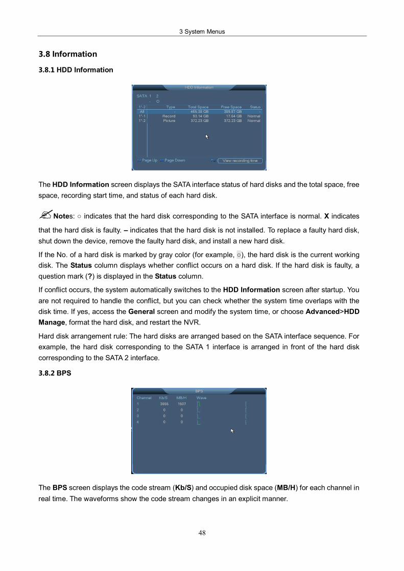
3 System Menus
48
3.8 Information
3.8.1 HDD Information
The HDD Information screen displays the SATA interface status of hard disks and the total space, free space, recording start time, and status of each hard disk.
?Notes: indicates that the hard disk corresponding to the SATA interface is normal. X indicates
that the hard disk is faulty. – indicates that the hard disk is not installed. To replace a faulty hard disk, shut down the device, remove the faulty hard disk, and install a new hard disk.
If the No. of a hard disk is marked by gray color (for example, ), the hard disk is the current working disk. The Status column displays whether conflict occurs on a hard disk. If the hard disk is faulty, a question mark (?) is displayed in the Status column.
If conflict occurs, the system automatically switches to the HDD Information screen after startup. You are not required to handle the conflict, but you can check whether the system time overlaps with the disk time. If yes, access the General screen and modify the system time, or choose Advanced>HDD Manage, format the hard disk, and restart the NVR.
Hard disk arrangement rule: The hard disks are arranged based on the SATA interface sequence. For example, the hard disk corresponding to the SATA 1 interface is arranged in front of the hard disk corresponding to the SATA 2 interface.
3.8.2 BPS
The BPS screen displays the code stream (Kb/S) and occupied disk space (MB/H) for each channel in real time. The waveforms show the code stream changes in an explicit manner.
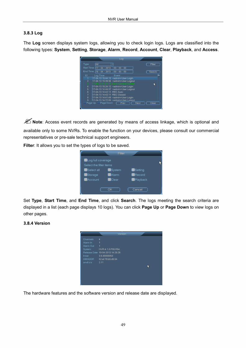
NVR User Manual
49
3.8.3 Log
The Log screen displays system logs, allowing you to check login logs. Logs are classified into the following types: System, Setting, Storage, Alarm, Record, Account, Clear, Playback, and Access.
?Note: Access event records are generated by means of access linkage, which is optional and
available only to some NVRs. To enable the function on your devices, please consult our commercial representatives or presale technical support engineers.
Filter: It allows you to set the types of logs to be saved.
Set Type, Start Time, and End Time, and click Search. The logs meeting the search criteria are displayed in a list (each page displays 10 logs). You can click Page Up or Page Down to view logs on other pages.
3.8.4 Version
The hardware features and the software version and release date are displayed.
NVR User Manual
50
4 Quick Start
4.1 Startup
Connect the power cable and press the power button (in the ON state). The power indicator is lit, and the NVR starts. The multiscreen video output mode is enabled by default. If the startup time is within the scheduled record time, the system automatically enables the scheduled recording function and operates properly.
4.2 Login
After normal startup, rightclick a menu and type the user name and password in the Login dialog box that is displayed.
?Notes:
(1) Two default users are available in the system: user admin and user guest. The default password of the two users is 123456.
(2) A password security policy is executed. You can try a password only five times within 30 minutes. After that, the account is locked.
(3) To ensure account security, change the default password in time. To add groups and users or modify users, see section 3.6.4 Account.
4.3 Shutdown
?Note: Before you replace a hard disk, disconnect the external power supply and open the shelf.
Method 1: Turn the main power switch to the OFF position.
Method 2: Choose SYSTEM MENU > Shut Down and select Shutdown.
Method 3: Choose SYSTEM MENU > Main Menu > Advanced > Shut Down and select Shutdown.
4.4 Power Recovery
If the system power supply is disconnected or the NVR is forcibly shut down when the NVR is in the recording, scheduled recoding, or alarm recording state, the NVR automatically saves the records generated before the power failure after poweron again and continues to work in the same state as that before the power failure.
4.5 Battery Replacement
Replace the button batteries of the NVR with batteries of the same model. Check the system time periodically and replace the batteries once a year to ensure the accuracy of the system time.
NVR User Manual
51
5 FAQ
1. Why does the host fail to start after the power supply is connected?
Check whether the power switch on the back of the host is turned on.
Check whether the startup operation is correct.
2. Why is there no display on the monitor? Why does the screen jitter?
Check whether the device is powered on. After poweron, the POWER indicator on the front panel will be lit.
Check whether the VGA cable is connected properly.
3. Why do color casts occur on the screen?
Check whether the VGA cable is connected properly and whether the VGA cable is intact.
4. Why does blank screen occurs after the host starts? Why is there no channel title on the
screen?
Access the channel setting screen and check whether local blocking is enabled. If yes, restore it to the default setting. Alternatively, access the default setting screen and restore all options to the default settings.
5. Why does the blocking effect occur during record playback on the host?
Record parameters are not set properly, reducing the record quality.
Bad sectors occur on the hard disks.
6. Why is there no record data available when manual recording is enabled?
Check whether the search criteria are correct. Ensure that manual recording is selected before you search for and play a record.
Ensure that hard disks are formatted into data areas.
Ensure that at least one read/write disk is available.
7. Why cannot scheduled recording be enabled? Why is there no record data within the
scheduled recording time period?
The scheduled recording time period is not set properly. The start time must be earlier than the end time.
The power supply is accidentally disconnected during in the scheduled recording time period.
The required data is overwritten.
Physical damage or logical errors occur on the hard disks. As a result, data cannot be displayed properly.
8. Why cannot alarm recording be enabled?
5 FAQ
52
The alarm recording time period is not set properly. The start time must be earlier than the end time.
No channel is selected for alarm recording. Select a proper channel.
The trigger settings are incorrect. Check alarm input connections and alarm trigger devices
9. Why is the record content discontinuous?
If this problem occurs in manual recording or scheduled recording, check whether a power failure or a voltage abnormity occurs.
If this problem occurs in alarm recording, check whether alarms are generated frequently. Recording is triggered when alarms occur and lasts for a certain period based on the preset recording time.
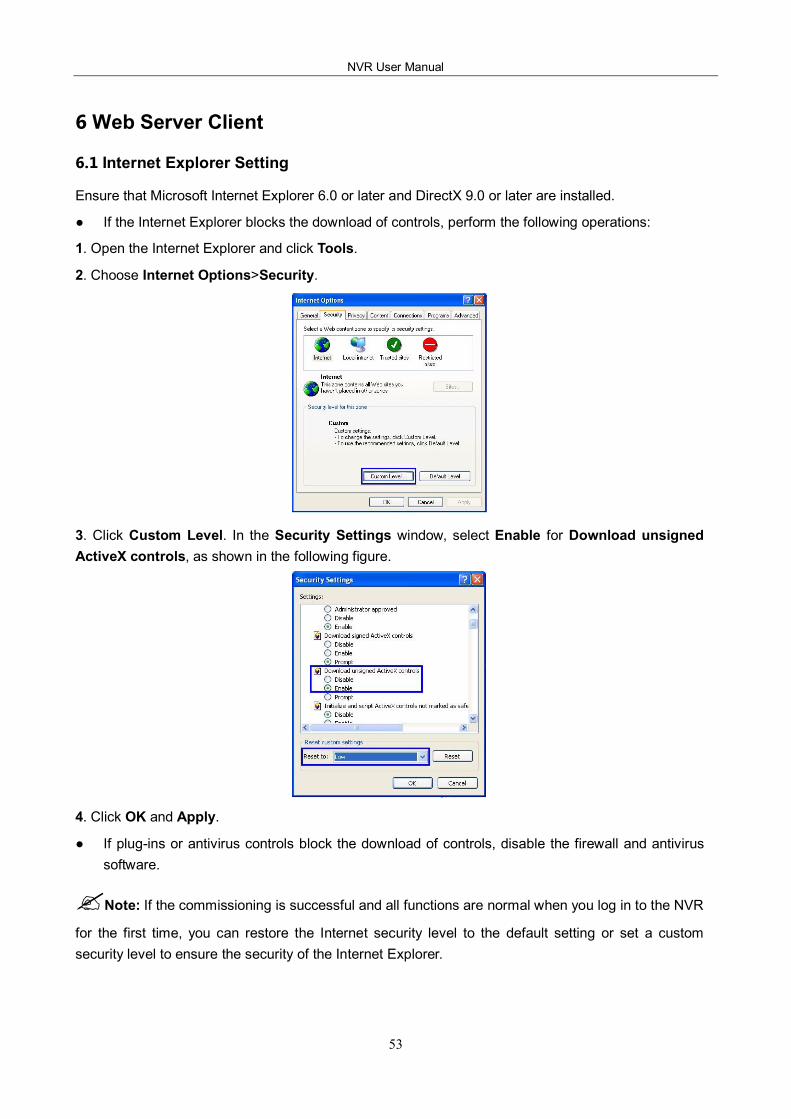
NVR User Manual
53
6 Web Server Client
6.1 Internet Explorer Setting
Ensure that Microsoft Internet Explorer 6.0 or later and DirectX 9.0 or later are installed.
If the Internet Explorer blocks the download of controls, perform the following operations:
1. Open the Internet Explorer and click Tools.
2. Choose Internet Options>Security.
3. Click Custom Level. In the Security Settings window, select Enable for Download unsigned ActiveX controls, as shown in the following figure.
4. Click OK and Apply.
If plugins or antivirus controls block the download of controls, disable the firewall and antivirus software.
?Note: If the commissioning is successful and all functions are normal when you log in to the NVR
for the first time, you can restore the Internet security level to the default setting or set a custom security level to ensure the security of the Internet Explorer.
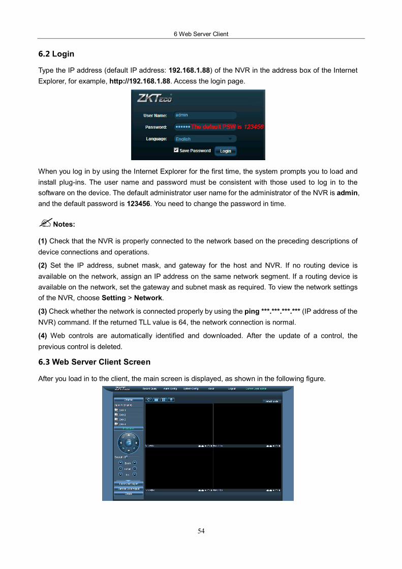
6 Web Server Client
54
6.2 Login
Type the IP address (default IP address: 192.168.1.88) of the NVR in the address box of the Internet Explorer, for example, http://192.168.1.88. Access the login page.
When you log in by using the Internet Explorer for the first time, the system prompts you to load and install plugins. The user name and password must be consistent with those used to log in to the software on the device. The default administrator user name for the administrator of the NVR is admin, and the default password is 123456. You need to change the password in time.
?Notes:
(1) Check that the NVR is properly connected to the network based on the preceding descriptions of device connections and operations.
(2) Set the IP address, subnet mask, and gateway for the host and NVR. If no routing device is available on the network, assign an IP address on the same network segment. If a routing device is available on the network, set the gateway and subnet mask as required. To view the network settings of the NVR, choose Setting > Network.
(3) Check whether the network is connected properly by using the ping ***.***.***.*** (IP address of the NVR) command. If the returned TLL value is 64, the network connection is normal.
(4) Web controls are automatically identified and downloaded. After the update of a control, the previous control is deleted.
6.3 Web Server Client Screen
After you load in to the client, the main screen is displayed, as shown in the following figure.
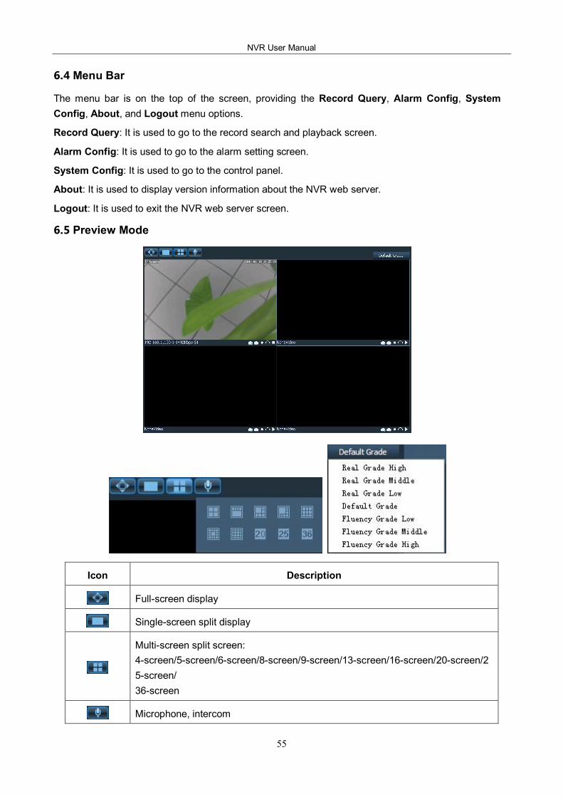
NVR User Manual
55
6.4 Menu Bar
The menu bar is on the top of the screen, providing the Record Query, Alarm Config, System Config, About, and Logout menu options.
Record Query: It is used to go to the record search and playback screen.
Alarm Config: It is used to go to the alarm setting screen.
System Config: It is used to go to the control panel.
About: It is used to display version information about the NVR web server.
Logout: It is used to exit the NVR web server screen.
6.5 Preview Mode
Icon Description
Fullscreen display
Singlescreen split display
Multiscreen split screen: 4screen/5screen/6screen/8screen/9screen/13screen/16screen/20screen/2 5screen/ 36screen
Microphone, intercom
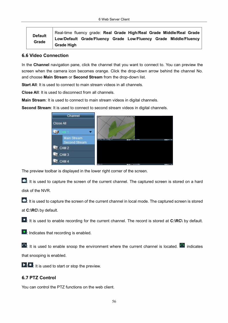
6 Web Server Client
56
Default Grade
Realtime fluency grade: Real Grade High/Real Grade Middle/Real Grade Low/Default Grade/Fluency Grade Low/Fluency Grade Middle/Fluency Grade High
6.6 Video Connection
In the Channel navigation pane, click the channel that you want to connect to. You can preview the screen when the camera icon becomes orange. Click the dropdown arrow behind the channel No. and choose Main Stream or Second Stream from the dropdown list.
Start All: It is used to connect to main stream videos in all channels.
Close All: It is used to disconnect from all channels.
Main Stream: It is used to connect to main stream videos in digital channels.
Second Stream: It is used to connect to second stream videos in digital channels.
The preview toolbar is displayed in the lower right corner of the screen.
: It is used to capture the screen of the current channel. The captured screen is stored on a hard
disk of the NVR.
: It is used to capture the screen of the current channel in local mode. The captured screen is stored
at C:\RC\ by default.
: It is used to enable recording for the current channel. The record is stored at C:\RC\ by default.
: Indicates that recording is enabled.
: It is used to enable snoop the environment where the current channel is located. indicates
that snooping is enabled.
/ : It is used to start or stop the preview.
6.7 PTZ Control
You can control the PTZ functions on the web client.

NVR User Manual
57
Direction Control: Control the pan/tilt directions (top, bottom, left, and right) of the PTZ. You can control a direction by clicking the corresponding arrow and hold. When you release the mouse, the direction is not under control.
Speed: Control the speed when the PTZ moves up, down, left, and right or in tour mode.
Zoom: Control the zooming of the PTZ camera lens.
Focus: Control the focus of the PTZ camera lens.
Iris: Control the aperture of the PTZ camera lens.
Preset: Type a value for Preset. The preset point of the PTZ cameras is invoked.
Auto Tour: Type a value for Auto Tour. Tours are enabled for PTZ cameras.
AutoPan: Enable PTZ cameras to rotate horizontally.
AutoScan: It is used to enable linear scanning for PTZ cameras.
Pattern: Control the auto pan/tilt of the PTZ.
PTZ Config: It allows you to set AutoScan, Pattern, Preset, and Tour.
Aux. On: It is used to start auxiliary devices.
Aux. Off: It is used to shut down auxiliary devices.
6.8 Screen Settings and Others
Icon Description
It is used to adjust the brightness of the screen.
It is used to adjust the contrast of the screen.
It is used to adjust the saturation of the screen.
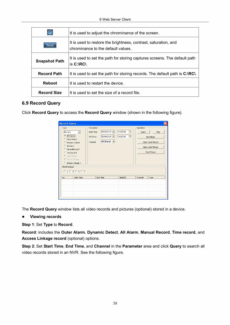
6 Web Server Client
58
It is used to adjust the chrominance of the screen.
It is used to restore the brightness, contrast, saturation, and chrominance to the default values.
Snapshot Path It is used to set the path for storing captures screens. The default path is C:\RC\.
Record Path It is used to set the path for storing records. The default path is C:\RC\.
Reboot It is used to restart the device.
Record Size It is used to set the size of a record file.
6.9 Record Query
Click Record Query to access the Record Query window (shown in the following figure).
The Record Query window lists all video records and pictures (optional) stored in a device.
l Viewing records
Step 1: Set Type to Record.
Record: includes the Outer Alarm, Dynamic Detect, All Alarm, Manual Record, Time record, and Access Linkage record (optional) options.
Step 2: Set Start Time, End Time, and Channel in the Parameter area and click Query to search all video records stored in an NVR. See the following figure.
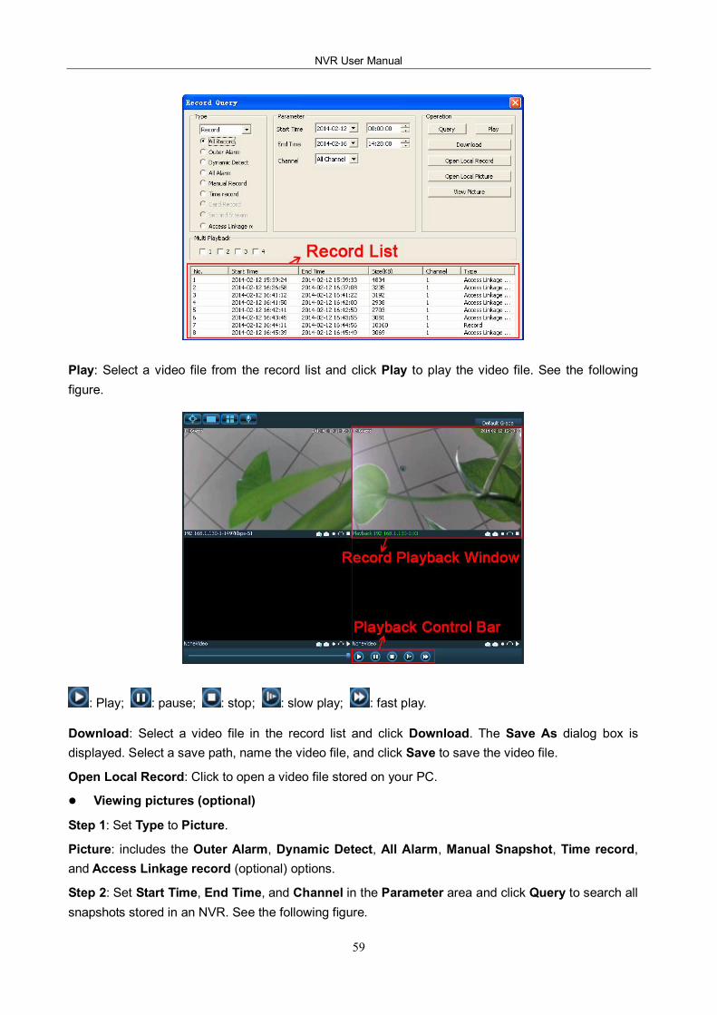
NVR User Manual
59
Play: Select a video file from the record list and click Play to play the video file. See the following figure.
: Play; : pause; : stop; : slow play; : fast play.
Download: Select a video file in the record list and click Download. The Save As dialog box is displayed. Select a save path, name the video file, and click Save to save the video file.
Open Local Record: Click to open a video file stored on your PC.
l Viewing pictures (optional)
Step 1: Set Type to Picture.
Picture: includes the Outer Alarm, Dynamic Detect, All Alarm, Manual Snapshot, Time record, and Access Linkage record (optional) options.
Step 2: Set Start Time, End Time, and Channel in the Parameter area and click Query to search all snapshots stored in an NVR. See the following figure.
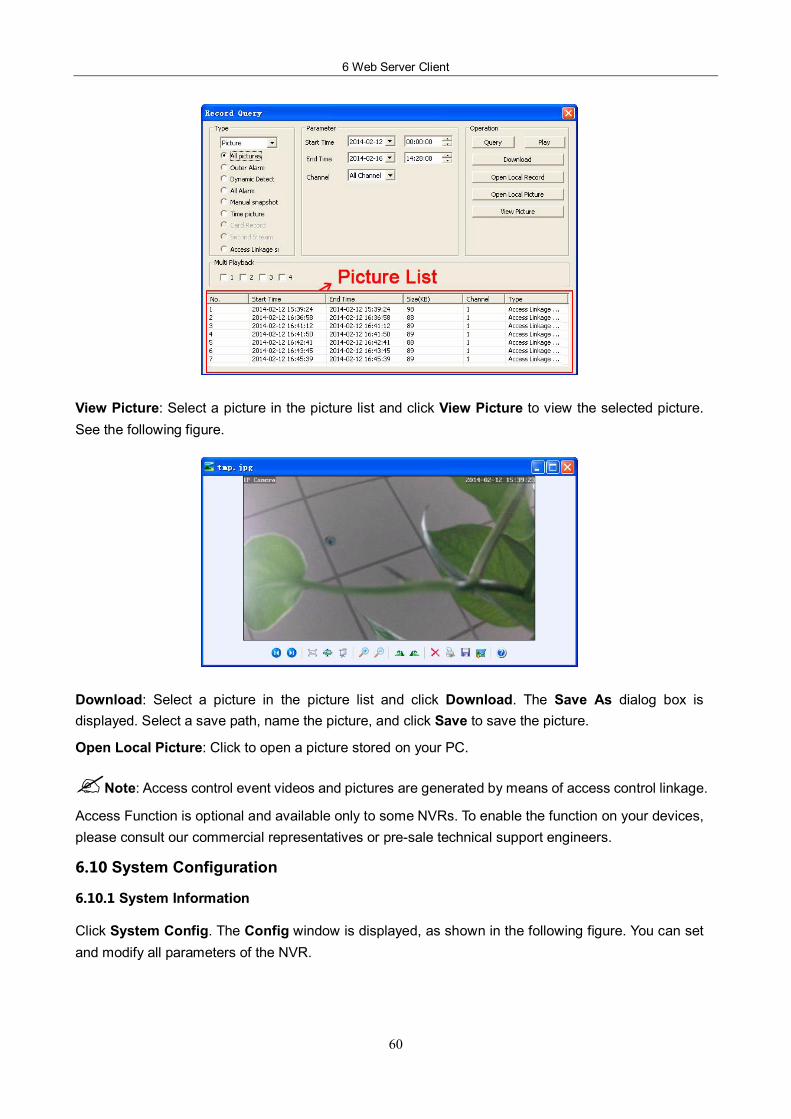
6 Web Server Client
60
View Picture: Select a picture in the picture list and click View Picture to view the selected picture. See the following figure.
Download: Select a picture in the picture list and click Download. The Save As dialog box is displayed. Select a save path, name the picture, and click Save to save the picture.
Open Local Picture: Click to open a picture stored on your PC.
?Note: Access control event videos and pictures are generated by means of access control linkage.
Access Function is optional and available only to some NVRs. To enable the function on your devices, please consult our commercial representatives or presale technical support engineers.
6.10 System Configuration
6.10.1 System Information
Click System Config. The Config window is displayed, as shown in the following figure. You can set and modify all parameters of the NVR.
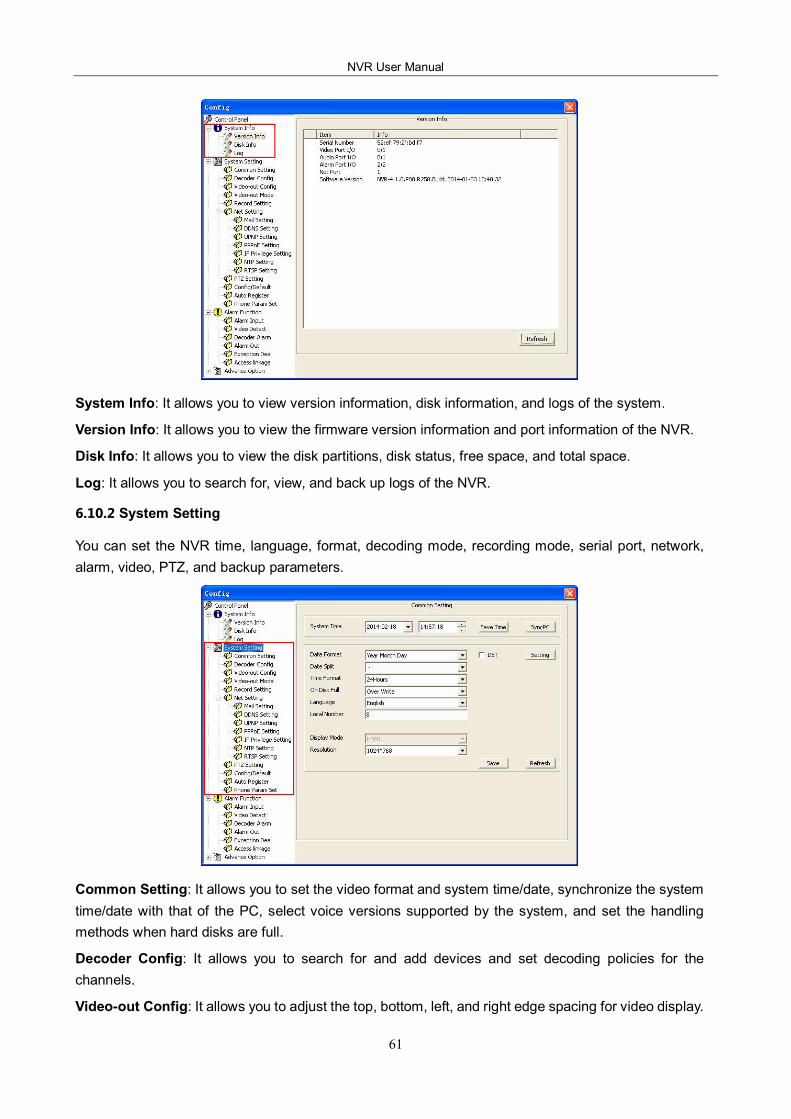
NVR User Manual
61
System Info: It allows you to view version information, disk information, and logs of the system.
Version Info: It allows you to view the firmware version information and port information of the NVR.
Disk Info: It allows you to view the disk partitions, disk status, free space, and total space.
Log: It allows you to search for, view, and back up logs of the NVR.
6.10.2 System Setting
You can set the NVR time, language, format, decoding mode, recording mode, serial port, network, alarm, video, PTZ, and backup parameters.
Common Setting: It allows you to set the video format and system time/date, synchronize the system time/date with that of the PC, select voice versions supported by the system, and set the handling methods when hard disks are full.
Decoder Config: It allows you to search for and add devices and set decoding policies for the channels.
Videoout Config: It allows you to adjust the top, bottom, left, and right edge spacing for video display.
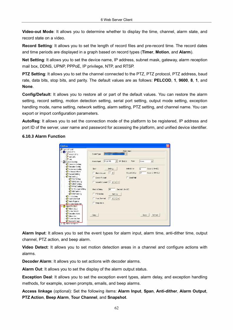
6 Web Server Client
62
Videoout Mode: It allows you to determine whether to display the time, channel, alarm state, and record state on a video.
Record Setting: It allows you to set the length of record files and prerecord time. The record dates and time periods are displayed in a graph based on record types (Timer, Motion, and Alarm).
Net Setting: It allows you to set the device name, IP address, subnet mask, gateway, alarm reception mail box, DDNS, UPNP, PPPoE, IP privilege, NTP, and RTSP.
PTZ Setting: It allows you to set the channel connected to the PTZ, PTZ protocol, PTZ address, baud rate, data bits, stop bits, and parity. The default values are as follows: PELCOD, 1, 9600, 8, 1, and None.
Config/Default: It allows you to restore all or part of the default values. You can restore the alarm setting, record setting, motion detection setting, serial port setting, output mode setting, exception handling mode, name setting, network setting, alarm setting, PTZ setting, and channel name. You can export or import configuration parameters.
AutoReg: It allows you to set the connection mode of the platform to be registered, IP address and port ID of the server, user name and password for accessing the platform, and unified device identifier.
6.10.3 Alarm Function
Alarm Input: It allows you to set the event types for alarm input, alarm time, antidither time, output channel, PTZ action, and beep alarm.
Video Detect: It allows you to set motion detection areas in a channel and configure actions with alarms.
Decoder Alarm: It allows you to set actions with decoder alarms.
Alarm Out: It allows you to set the display of the alarm output status.
Exception Deal: It allows you to set the exception event types, alarm delay, and exception handling methods, for example, screen prompts, emails, and beep alarms.
Access linkage (optional): Set the following items: Alarm Input, Span, Antidither, Alarm Output, PTZ Action, Beep Alarm, Tour Channel, and Snapshot.
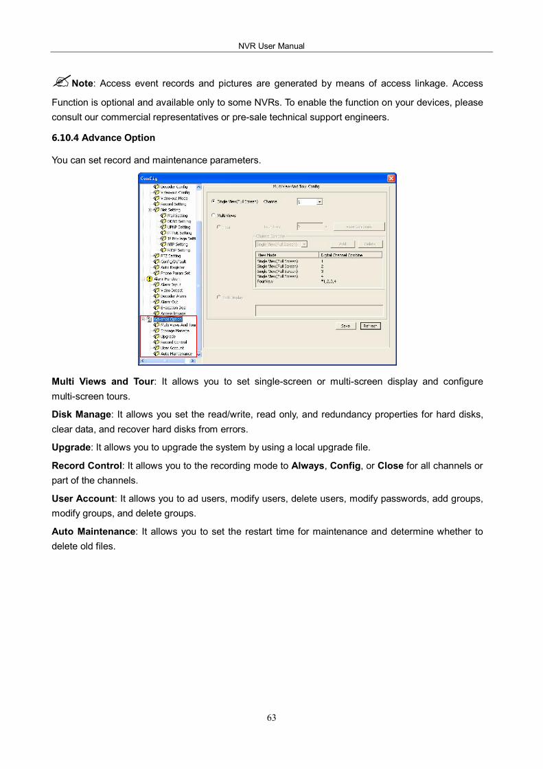
NVR User Manual
63
?Note: Access event records and pictures are generated by means of access linkage. Access
Function is optional and available only to some NVRs. To enable the function on your devices, please consult our commercial representatives or presale technical support engineers.
6.10.4 Advance Option
You can set record and maintenance parameters.
Multi Views and Tour: It allows you to set singlescreen or multiscreen display and configure multiscreen tours.
Disk Manage: It allows you set the read/write, read only, and redundancy properties for hard disks, clear data, and recover hard disks from errors.
Upgrade: It allows you to upgrade the system by using a local upgrade file.
Record Control: It allows you to the recording mode to Always, Config, or Close for all channels or part of the channels.
User Account: It allows you to ad users, modify users, delete users, modify passwords, add groups, modify groups, and delete groups.
Auto Maintenance: It allows you to set the restart time for maintenance and determine whether to delete old files.