Embed Size (px)
Citation preview
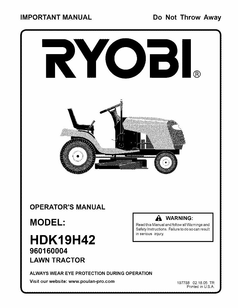
IMPORTANT MANUAL Do Not Throw Away
®
OPERATOR'S MAN UAL
MODEL:
HDK19H42960160004LAWN TRACTOR
WARNING:Read this Manual and follow all Warnings andSafety Instructions. Failure to do so can resultin serious injury.
ALWAYS WEAR EYE PROTECTION DURING OPERATION
Visit our website: www.poulan-pro.com 197788 02.18.05 TRPrinted in U.S.A.
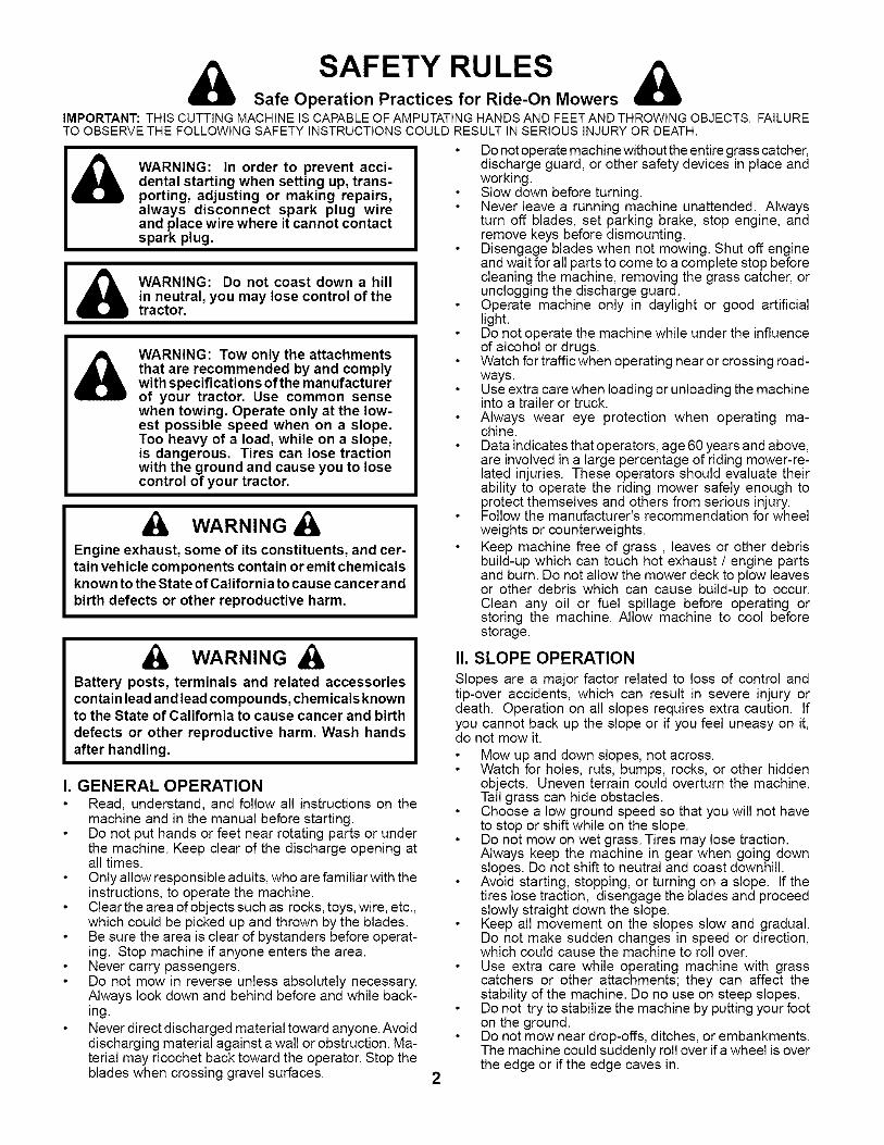
SAFETY RULESSafe Operation Practices for Ride-On Mowers
IMPORTANT: THIS CUTTING MACHINE IS CAPABLE OF AMPUTATING HANDS AND FEET AND THROWING OBJECTS. FAILURETO OBSERVE THE FOLLOWING SAFETY INSTRUCTIONS COULD RESULT IN SERIOUS INJURY OR DEATH.
Do not operate machine without the entire grass catcher,WARNING: In order to prevent acci-dental starting when setting up, trans-porting, adjusting or making repairs,always disconnect spark plug wireand place wire where it cannot contactspark plug.
l i_) WARNING: Do not coast down a hill I
I
in neutral, you may lose control of the Itractor.
& WARNING: Tow only the attachmentsthat are recommended by and complywith specifications of the manufacturerof your tractor. Use common sensewhen towing. Operate only at the low-est possible speed when on a slope.Too heavy of a load, while on a slope,is dangerous. Tires can lose tractionwith the ground and cause you to losecontrol of your tractor.
WARNING
Engine exhaust, some of its constituents, and cer-tain vehicle components contain or emit chemicalsknown to the State of California to cause cancer andbirth defects or other reproductive harm.
WARNINGBattery posts, terminals and related accessoriescontain lead and lead compounds, chemicals knownto the State of California to cause cancer and birthdefects or other reproductive harm. Wash handsafter handling.
I. GENERAL OPERATIONRead, understand, and follow all instructions on themachine and in the manual before starting.Do not put hands or feet near rotating parts or underthe machine. Keep clear of the discharge opening atall times.Only allow responsible adults, who are familiar with theinstructions, to operate the machine.Clear the area of objects such as rocks, toys, wire, etc.,which could be picked up and thrown by the blades.Be sure the area is clear of bystanders before operat-ing. Stop machine if anyone enters the area.Never carry passengers.Do not mow in reverse unless absolutely necessary.Always look down and behind before and while back-ing.Never direct discharged material toward anyone. Avoiddischarging material against a wall or obstruction. Ma-terial may ricochet back toward the operator. Stop theblades when crossing gravel surfaces. 2
discharge guard, or other safety devices in place andworking.Slow down before turning.Never leave a running machine unattended. Alwaysturn off blades, set parking brake, stop engine, andremove keys before dismounting.Disengage blades when not mowing. Shut off engineand wait for all parts to come to a complete stop beforecleaning the machine, removing the grass catcher, orunclogging the discharge guard.Operate machine only in daylight or good artificiallight.Do not operate the machine while under the influenceof alcohol or drugs.Watch for traffic when operating near or crossing road-ways.Use extra care when loading or unloading the machineinto a trailer or truck.Always wear eye protection when operating ma-chine.Data indicates that operators, age 60 years and above,are involved in a large percentage of riding mower-re-lated injuries. These operators should evaluate theirability to operate the riding mower safely enough toprotect themselves and others from serious injury.Follow the manufacturer's recommendation for wheelweights or counterweights.Keep machine free of grass, leaves or other debrisbuild-up which can touch hot exhaust / engine partsand burn. Do not allow the mower deck to plow leavesor other debris which can cause build-up to occur.Clean any oil or fuel spillage before operating orstoring the machine. Allow machine to cool beforestorage.
II. SLOPE OPERATION
Slopes are a major factor related to loss of control andtip-over accidents, which can result in severe injury ordeath. Operation on all slopes requires extra caution. Ifyou cannot back up the slope or if you feel uneasy on it,do not mow it.
Mow up and down slopes, not across.Watch for holes, ruts, bumps, rocks, or other hiddenobjects. Uneven terrain could overturn the machine.Tall grass can hide obstacles.Choose a low ground speed so that you will not haveto stop or shift while on the slope.Do not mow on wet grass. Tires may lose traction.Always keep the machine in gear when going downslopes. Do not shift to neutral and coast downhill.Avoid starting, stopping, or turning on a slope. If thetires lose traction, disengage the blades and proceedslowly straight down the slope.Keep all movement on the slopes slow and gradual.Do not make sudden changes in speed or direction,which could cause the machine to roll over.Use extra care while operating machine with grasscatchers or other attachments; they can affect thestability of the machine. Do no use on steep slopes.Do not try to stabilize the machine by putting your footon the ground.Do not mow near drop-offs, ditches, or embankments.The machine could suddenly roll over ifa wheel is overthe edge or if the edge caves in.
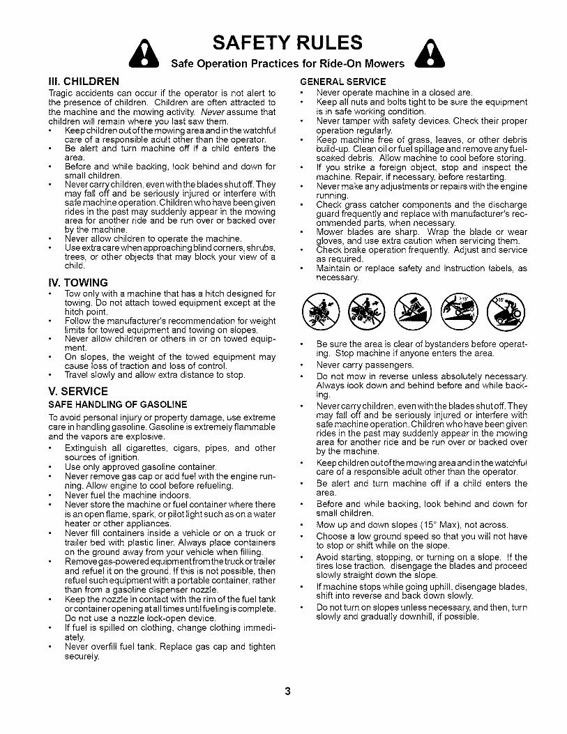
SAFETY RULESSafe Operation Practices for Ride-On Mowers
II1. CHILDRENTragic accidents can occur if the operator is not alert tothe presence of children. Children are often attracted tothe machine and the mowing activity. Never assume thatchildren will remain where you last saw them.
Keep child ren out of the mowing area and inthe watchfulcare of a responsible adult other than the operator.Be alert and turn machine off if a child enters thearea.Before and while backing, look behind and down forsmall children.Never carry children, even with the blades shut off. Theymay fall off and be seriously injured or interfere withsafe machine operation. Children who have been givenrides in the past may suddenly appear in the mowingarea for another ride and be run over or backed overby the machine.Never allow children to operate the machine.Use extra care when approaching blind corners, shrubs,trees, or other objects that may block your view of achild.
IV. TOWINGTow only with a machine that has a hitch designed fortowing. Do not attach towed equipment except at thehitch point.Follow the manufacturer's recommendation for weightlimits for towed equipment and towing on slopes.Never allow children or others in or on towed equip-ment.On slopes, the weight of the towed equipment maycause loss of traction and loss of control.Travel slowly and allow extra distance to stop.
V. SERVICESAFE HANDLING OF GASOLINE
To avoid personal injury or property damage, use extremecare in handling gasoline. Gasoline is extremely flammableand the vapors are explosive.
Extinguish all cigarettes, cigars, pipes, and othersources of ignition.Use only approved gasoline container.Never remove gas cap or add fuel with the engine run-ning. Allow engine to cool before refueling.Never fuel the machine indoors.Never store the machine or fuel container where thereis an open flame, spark, or pilot light such as on a waterheater or other appliances.Never fill containers inside a vehicle or on a truck ortrailer bed with plastic liner. Always place containerson the ground away from your vehicle when filling.Remove gas-powered equipmentfrom the truck ortrailerand refuel it on the ground. If this is not possible, thenrefuel such equipment with a portable container, ratherthan from a gasoline dispenser nozzle.Keep the nozzle in contact with the rim of the fuel tankor container opening at all times until fueling is complete.Do not use a nozzle lock-open device.If fuel is spilled on clothing, change clothing immedi-ately.Never overfill fuel tank. Replace gas cap and tightensecurely.
GENERAL SERVICENever operate machine in a closed are.Keep all nuts and bolts tight to be sure the equipmentis in safe working condition.Never tamper with safety devices. Check their properoperation regularly.Keep machine free of grass, leaves, or other debrisbuild-up. Clean oil or fuel spillage and remove any fuel-soaked debris. Allow machine to cool before storing.If you strike a foreign object, stop and inspect themachine. Repair, if necessary, before restarting.Never make any adjustments or repairs with the enginerunning.Check grass catcher components and the dischargeguard frequently and replace with manufacturer's rec-ommended parts, when necessary.Mower blades are sharp. Wrap the blade or weargloves, and use extra caution when servicing them.Check brake operation frequently. Adjust and serviceas required.Maintain or replace safety and instruction labels, asnecessary.
®@@@@Be sure the area is clear of bystanders before operat-ing. Stop machine if anyone enters the area.Never carry passengers.Do not mow in reverse unless absolutely necessary.Always look down and behind before and while back-ing.Never carry children, even with the blades shut off. Theymay fall off and be seriously injured or interfere withsafe machine operation. Children who have been givenrides in the past may suddenly appear in the mowingarea for another ride and be run over or backed overby the machine.Keep child ren out of the mowing area and inthe watchfulcare of a responsible adult other than the operator.Be alert and turn machine off if a child enters thearea.Before and while backing, look behind and down forsmall children.
Mow up and down slopes (15° Max), not across.Choose a low ground speed so that you will not haveto stop or shift while on the slope.Avoid starting, stopping, or turning on a slope. If thetires lose traction, disengage the blades and proceedslowly straight down the slope.If machine stops while going uphill, disengage blades,shift into reverse and back down slowly.Do not turn on slopes unless necessary, and then, turnslowly and gradually downhill, if possible.

PRODUCT SPECIFICATIONSGasoline Capacity 2.0 Gallonsand Type: Unleaded Regular
Oil Type (API-SG-SL): SAE 10W30 (above 32°F)SAE 5W-30 (below 32°F)
Oil Capacity: 3.0 Pints
Spark Plug: Champion RC12YC(Gap: .030")
Ground Speed (MPH): Forward: 5.5Reverse: 2.4
Tire Pressure: Front: 14 PSIRear: 10 PSI
Charging System: 15 Amps @ 3600 RPM
Battery: AMP/HR: 35Min. CCA: 280Case Size: U1R
Blade Torque: 27-35 FT. LBS.
CONGRATULATIONS on your purchase of a new tractor.Ithas been designed, engineered and manufactured to giveyou the best possible dependability and performance.
Should you experience any problem you cannot easily rem-edy, please contact your nearest authorized service center/department. We have competent, well-trained techniciansand the proper tools to service or repair this tractor.Please read and retain this manual. The instructions willenable you to assemble and maintain your tractor properly.Always observe the "SAFETY RULES".
CUSTOMER RESPONSIBILITIESRead and observe the safety rules.Follow a regular schedule in maintaining, caring forand using your tractor.Follow the instructions under "Maintenace" and "Stor-age" sections of this owner's manual.
WARNING: This tractor is equipped with an internal com-bustion engine and should not be used on or near anyunimproved forest-covered, brush-covered orgrass-coveredland unless the engine's exhaust system is equipped witha spark arrester meeting applicable local or state laws (ifany). If a spark arrester is used, it should be maintainedin effective working order by the operator.
A spark arrester for the muffler is available through yournearest authorized service center/department.
TABLE OF CONTENTS
SAFETY RULES ......................................................... 2-3PRODUCT SPECIFICATIONS ....................................... 4CUSTOM ER RESPONSIBILITIES ................................. 4ASSEMBLY ................................................................. 6-8OP ERATION ............................................................. 9-14MAINTENANCE SCHEDULE ...................................... 15
MAINTENANCE ..................................................... 15-18SERVICE AND ADJUSTMENTS ............................ 19-23STORAGE .................................................................... 24TROUBLESHOOTING ............................................ 25-26WARRANTY ................................................................. 27
4
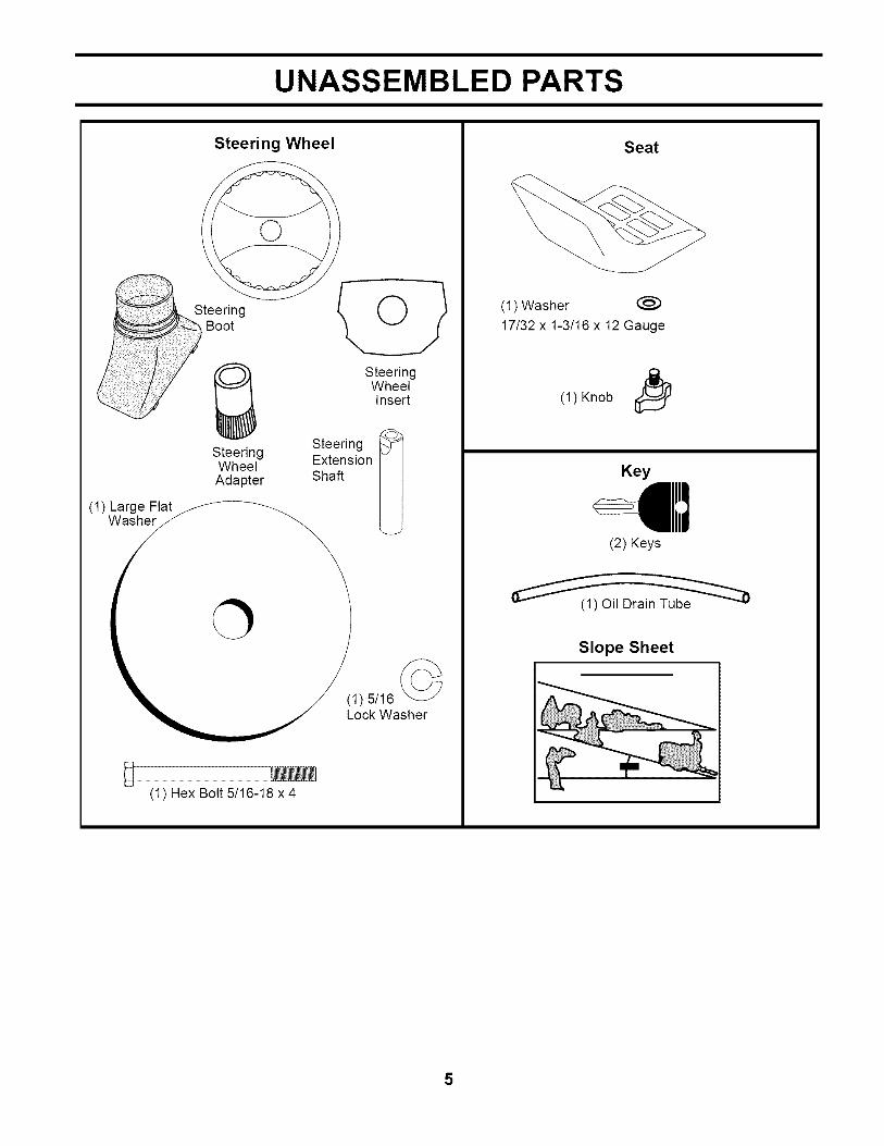
UNASSEMBLED PARTS
Steering Wheel
SteeringBoot
(1) Large FlatWasher
SteeringWheel
Adapter
(1) Hex Bolt 5/16-18 x4
SteeringWheelInsert
Steering
ExtensionShaft
(1) 5/16 (_
Lock Washer
Seat
(1) Washer @
17/32 x 1-3/16 x 12 Gauge
(1) Knob I_
Key
(2) Keys
Slope Sheet
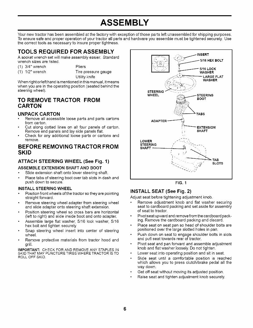
ASSEMBLY
Your new tractor has been assembled at the factory with exception of those parts left unassembled for shipping purposes.To ensure safe and proper operation of your tractor all parts and hardware you assemble must be tightened securely. Usethe correct tools as necessary to insure proper tightness.
TOOLS REQUIRED FOR ASSEMBLYA socket wrench set will make assembly easier. Standardwrench sizes are listed.
(1) 3/4" wrench Pliers(t) 1/2" wrench Tire pressure gauge
Utility knifeWhen right or left hand is mentioned in this manual, it meanswhen you are in the operating position (seated behind thesteering wheel).
TO REMOVE TRACTOR FROMCARTON
UNPACK CARTONRemove all accessible loose parts and parts cartonsfrom carton.Cut along dotted lines on all four panels of carton.Remove end panels and lay side panels flat.Check for any additional loose parts or cartons andremove.
BEFORE REMOVING TRACTOR FROMSKID
ATTACH STEERING WHEEL (See Fig. 1)ASSEMBLE EXTENSION SHAFT AND BOOT
Slide extension shaft onto lower steering shaft.Place tabs of steering boot over tab slots in dash andpush down to secure.
INSTALL STEERING WHEELPosition front wheels of the tractor so they are pointingstraight forward.Remove steering wheel adapter from steering wheeland slide adapter onto steering shaft extension.Position steering wheel so cross bars are horizontal(left to right) and slide inside boot and onto adapter.Assemble large flat washer, 5/16 lock washer, 5/16hex bolt and tighten securely.Snap steering wheel insert into center of steeringwheel.Remove protective materials from tractor hood andgrill.
IMPORTANT: CHECK FOR AND REMOVEANY STAPLES INSKIDTHAT MAYPUNCTURETIRESWHERETRACTOR ISTOROLL OFFSKID.
STEERING " ............WHEEL
BOOT
LOWERSTEERINGSHAFT .......
i SHAFT
L
/ - _ TABb- / --/'- - SLOTS
FIG. 1
INSTALL SEAT (See Fig. 2)Adjust seat before tightening adjustment knob.
Remove adjustment knob and flat washer securingseat to cardboard packing and set aside for assemblyof seat to tractor.
Pivotseat upward and remove from the cardboard pack-ing. Remove the cardboard packing and discard.Place seat on seat pan so head of shoulder bolts arepositioned over the large slotted holes in pan.Push down on seat to engage shoulder bolts in slotsand pull seat towards rear of tractor.Pivot seat and pan forward and assemble adjustmentknob and flat washer loosely. Do not tighten.Lower seat into operating position and sit in seat.Slide seat until a comfortable position is reachedwhich allows you to press clutch/brake pedal all theway down.Get off seat without moving its adjusted position.Raise seat and tighten adjustment knob securely.
6

ASSEMBLY
SEAT
SEAT PAN
SHOULDERBOLTS
FLAT WASHER
NN .....ADJUSTMENTKNOB
FIG. 2
CHECK BATTERY (See Fig. 3)Lift seat pan to raised position.If this battery is put into service after month and yearindicated on label (label located between terminals)charge battery for minimum of one hour at 6-10 amps.(See "BATTERY" in MAINTENANCE section of thismanual for charging instructions).
SEAT
LABEL
NOTE: You may now roll or drive your tractor off the skid.Follow the appropriate instruction below to remove thetractor from the skid.TO ROLL TRACTOR OFF SKID (See Op-eration section for location and function ofcontrols)
Press lift lever plunger and raise attachment lift leverto its highest position.Release parking brake by depressing clutch/brakepedal.Place freewheel control in "transmission disengagedposition" (See "TO TRANSPORT" in the Operationsection of this manual).Roll tractor forward off skid.Remove banding holding the deflector shield up againsttractor.
TO DRIVE TRACTOR OFF SKID (See Op-eration section for location and function ofcontrols)_IbWARNING: Before starting, read, understand and followall instructions in the Operation section of this manual. Besure tractor is in a well-ventilated area. Be sure the area infront of tractor is clear of other people and objects.
Be sure all the above assembly steps have been com-pleted.Check engine oil level and fill fuel tank with gasoline.Place freewheel control in "transmission engaged"position (see "TO TRANSPORT" in Operation sectionof this manual).Sit on seat in operating position, depress clutch/brakepedal and set the parking brake.Place motion control lever in neutral (N) position.Press lift lever plunger and raise attachment lift leverto its highest position.Start the engine. After engine has started, move throttlecontrol to idle position.Release parking brake.Slowly move the motion control lever forward and slowlydrive tractor off skid.
Apply brake to stop tractor, set parking brake and placemotion control lever in neutral position.Turn ignition key to "STOP" position.
Continue with the instructions that follow.
FIG. 3

ASSEMBLY
CHECK TIRE PRESSURE
The tires on your tractor were overinflated at the factoryfor shipping purposes. Correct tire pressure is importantfor best cutting performance.
Reduce tire pressure to PSI shown in "PRODUCTSPECIFICATIONS" section of this manual.
CHECK DECK LEVELNESS
For best cutting results, mower housing should be properlyleveled. See "TO LEVEL MOWER HOUSING" inthe Serviceand Adjustments section of this manual.
CHECK FOR PROPER POSITION OF ALLBELTS
See the figures that are shown for replacing motion andmower blade drive belts in the Service and Adjustmentssection of this manual. Verify that the belts are routedcorrectly.
CHECK BRAKE SYSTEM
After you learn how to operate your tractor, check to see thatthe brake is properly adjusted. See "TO ADJUST BRAKE"in the Service and Adjustments section of this manual.
,/'CHECKLIST
BEFORE YOU OPERATE YOUR NEW TRACTOR, WEWISH TOASSURE THAT YOU RECEIVE THE BES T PER-FORMANCEAND SATISFACTION FROM THIS QUALITYPROD UCT.
PLEASE REVIEW THE FOLLOWING CHECKLIST.,/ All assembly instructions have been completed.
,/ No remaining loose parts in carton.
,/ Battery is properly prepared and charged. (Minimum1 hour at 6 amps).
,/ Seat is adjusted comfortably and tightened securely.,/ All tires are properly inflated. (For shipping purposes,
the tires were overinflated at the factory).
,/ Be sure mower deck is properly leveled side-to-side/front-to-rear for best cutting results. (Tires must beproperly inflated for leveling).
,/ Check mower and drive belts. Be sure they are routedproperly around pulleys and inside all belt keepers.
,/ Check wiring. See that all connections are still secureand wires are properly clamped.
,/ Before driving tractor, be sure freewheel control is in"transmission engaged" position (see "TO TRANS-PORT" in the Operation section of this manual).
WHILE LEARNING HOWTO USEYOURTRACTOR, PAYEXTRA ATTENTION TO THE FOLLOWING IMPORTANTITEMS:
,/ Engine oil is at proper level.
,/ Fuel tank is filled with fresh, clean, regular unleadedgasoline.
,/ Become familiar with all controls, their location andfunction. Operate them before you start the engine.
,/ Be sure brake system is in safe operating condition.
,/ Be sure Operator Presence System and Reverse Op-eration System (ROS) are working properly (See theOperation and Maintenance sections in this manual).
,/ It is important to purge the transmission before oper-ating your tractor for the first time. Follow proper start-ing and transmission purging instructions (See "TOSTART ENGINE" and "PURGE TRANSMISSION" inthe Operation section of this manual).
8
OPERATION
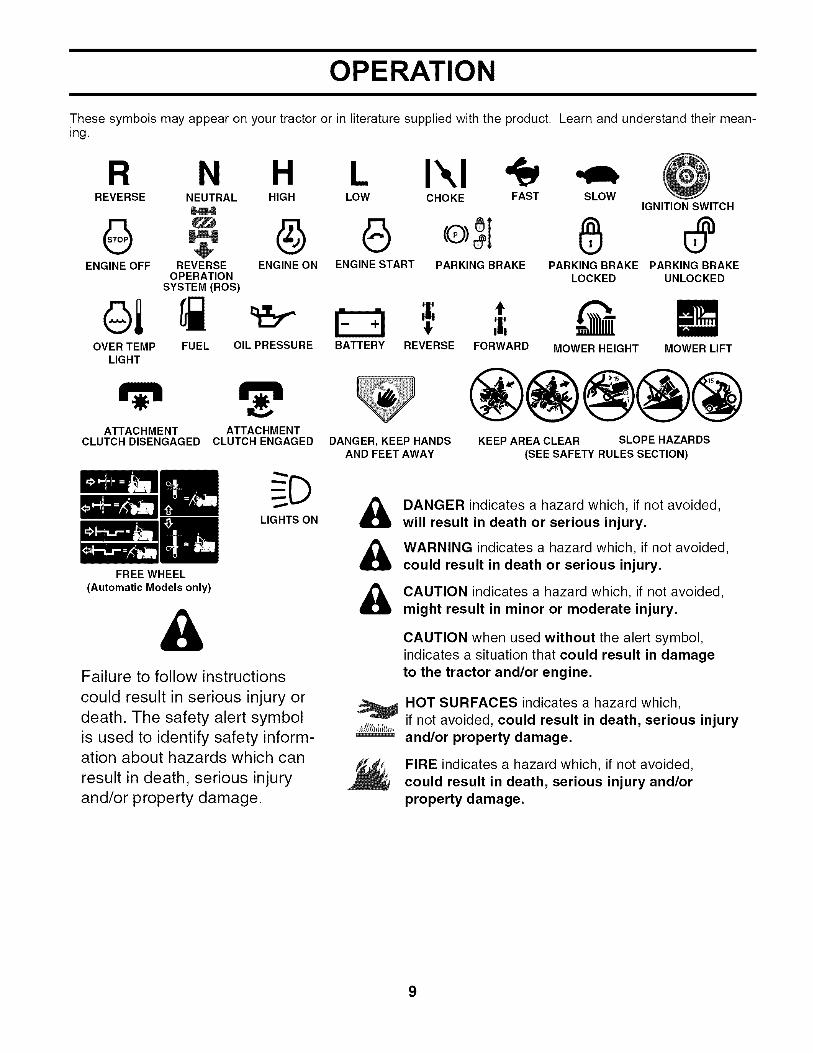
These symbols may appear on your tractor or in literature supplied with the product. Learn and understand their mean-ing.
R N H I\1CHOKE FASTREVERSE NEUTRAL HIGH LOW SLOW
IGNITION SWITCH
ENGINE OFF REVERSE ENGINE ON ENGINE START PARKING BRAKE PARKING BRAKE PARKING BRAKEOPERATION LOCKED UNLOCKED
SYSTEM(ROS)
t,BATTERY REVERSE FORWARD MOWER HEIGHTFUEL OIL PRESSURE MOWER LIFTOVER TEMP
LIGHT
ATTACHMENT ATTACHMENTCLUTCH DISENGAGED CLUTCH ENGAGED
LIGHTS ON
FREE WHEEL
(Automatic Models only)
&Failure to follow instructions
could result in serious injury or
death. The safety alert symbol
is used to identify safety inform-ation about hazards which can
result in death, serious injury
and/or property damage.
DANGER, KEEP HANDSAND FEET AWAY
®@@@@KEEP AREA CLEAR SLOPE HAZARDS
(SEE SAFETY RULES SECTION)
&&&
DANGER indicates a hazard which, if not avoided,
will result in death or serious injury.
WARNING indicates a hazard which, if not avoided,
could result in death or serious injury.
CAUTION indicates a hazard which, if not avoided,
might result in minor or moderate injury.
CAUTION when used without the alert symbol,indicates a situation that could result in damageto the tractor and/or engine.
HOT SURFACES indicates a hazard which,
if not avoided, could result in death, serious injuryand/or property damage.
FIRE indicates a hazard which, if not avoided,
could result in death, serious injury and/orproperty damage.
OPERATION
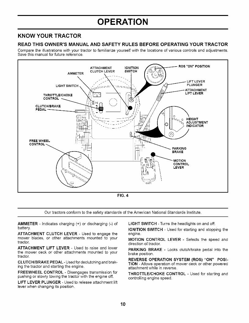
KNOW YOUR TRACTOR
READ THIS OWNER'S MANUAL AND SAFETY RULES BEFORE OPERATING YOUR TRACTOR
Compare the illustrations with your tractor to familiarize yourself with the locations of various controls and adjustments.Save this manual for future reference.
AMMETER
LIGHT SWITCH _
THROTTLE/CHOKECONTROL
CLUTCH/BRAKE
ATTACHMENT IGNITIONCLUTCH LEVER SWITCH
ROS "ON" POSITION
LIFT LEVERPLUNGER
LIFT LEVER
...- ......o HEIGHT
ADJUSTMENTINDICATOR
FREE WHEEL
PARKINGBRAKE
MOTIONCONTROLLEVER
02871
FIG. 4
Our tractors conform to the safety standards of the American National Standards Institute.
AMMETER - Indicates charging (+) or discharging (-) ofbattery.
ATTACHMENT CLUTCH LEVER - Used to engage themower blades, or other attachments mounted to yourtractor.
ATTACHMENT LIFT LEVER - Used to raise and lowerthe mower deck or other attachments mounted to yourtractor.
CLUTCH/BRAKE PEDAL- Used for declutching and brak-ing the tractor and starting the engine.
FREEWHEEL CONTROL - Disengages transmission forpushing or slowly towing the tractor with the engine off.LIFT LEVER PLUNGER - Used to release attachment liftlever when changing its position.
LIGHT SWITCH - Turns the headlights on and off.
IGNITION SWITCH - Used for starting and stopping theengine.
MOTION CONTROL LEVER - Selects the speed anddirection of tractor.
PARKING BRAKE - Locks clutch/brake pedal into thebrake position.
REVERSE OPERATION SYSTEM (ROS) "ON" POSI-TION - Allows operation of mower deck or other poweredattachment while in reverse.
THROTTLE/CHOKE CONTROL - Used for starting andcontrolling engine speed.
10
OPERATION
The operation of any tractor can result in foreign objects thrown into the eyes, whichcan result in severe eye damage. Always wear safety glasses or eye shields while op-erating your tractor or performing any adjustments or repairs. We recommend a widevision safety mask over spectacles or standard safety glasses.
HOW TO USE YOUR TRACTOR
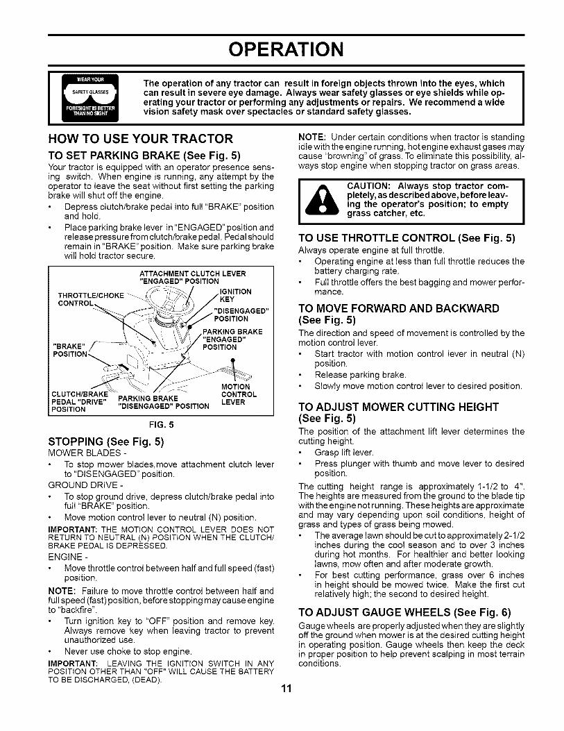
TO SET PARKING BRAKE (See Fig. 5)Your tractor is equipped with an operator presence sens-ing switch. When engine is running, any attempt by theoperator to leave the seat without first setting the parkingbrake will shut off the engine.
Depress clutch/brake pedal into full "BRAKE" positionand hold.
Place parking brake lever in "ENGAGED" position andrelease pressure from clutch/brake pedal. Pedal shouldremain in "BRAKE" position. Make sure parking brakewill hold tractor secure.
CLUTCH/BRAKEPEDAL "DRIVE"POSITION
PARKING BRAKE"DISENGAGED" POSITION
MOTIONCONTROLLEVER
FIG. 5
STOPPING (See Fig. 5)MOWER BLADES -
To stop mower blades, move attachment clutch leverto "DISENGAGED" position.
GROUND DRIVE-
To stop ground drive, depress clutch/brake pedal intofull "BRAKE" position.Move motion control lever to neutral (N) position.
IMPORTANT: THE MOTION CONTROL LEVER DOES NOTRETURN TO NEUTRAL (N) POSITION WHEN THE CLUTCH/BRAKE PEDAL IS DEPRESSED.
ENGINE -Move throttle control between half and full speed (fast)position.
NOTE: Failure to move throttle control between half andfull speed (fast) position, before stopping may cause engineto "backfire".
Turn ignition key to "OFF" position and remove key.Always remove key when leaving tractor to preventunauthorized use.
Never use choke to stop engine.IMPORTANT: LEAVING THE IGNITION SWITCH IN ANYPOSITION OTHER THAN "OFF" WILL CAUSE THE BATTERYTO BE DISCHARGED, (DEAD),
NOTE: Under certain conditions when tractor is standingidle with the engine running, hot engine exhaust gases maycause "browning" of grass. To eliminate this possibility, al-ways stop engine when stopping tractor on grass areas.
CAUTION: Always stop tractor com-pletely, as described above, before leav-ing the operator's position; to emptygrass catcher, etc.
TO USE THROTTLE CONTROL (See Fig. 5)Always operate engine at full throttle.
Operating engine at less than full throttle reduces thebattery charging rate.Full throttle offers the best bagging and mower perfor-mance.
TO MOVE FORWARD AND BACKWARD(See Fig. 5)The direction and speed of movement is controlled by themotion control lever.
Start tractor with motion control lever in neutral (N)position.Release parking brake.Slowly move motion control lever to desired position.
TO ADJUST MOWER CUTTING HEIGHT
(See Fig. 5)The position of the attachment lift lever determines thecutting height.
Grasp lift lever.Press plunger with thumb and move lever to desiredposition.
The cutting height range is approximately 1-t/2 to 4".The heights are measured from the ground to the blade tipwith the engine not running. These heights are approximateand may vary depending upon soil conditions, height ofgrass and types of grass being mowed.
The average lawn should be cut to approximately 2-1/2inches during the cool season and to over 3 inchesduring hot months. For healthier and better lookinglawns, mow often and after moderate growth.For best cutting performance, grass over 6 inchesin height should be mowed twice. Make the first cutrelatively high; the second to desired height.
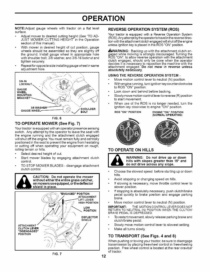
TO ADJUST GAUGE WHEELS (See Fig. 6)Gauge wheels are properly adjusted when they are slightlyoff the ground when mower is at the desired cutting heightin operating position. Gauge wheels then keep the deckin proper position to help prevent scalping in most terrainconditions.
11
OPERATION
NOTE:Adjust gauge wheels with tractor on a flat levelsurface.
Adjust mower to desired cutting height (See "TO AD-JUST MOWER CUTTING HEIGHT" in the Operationsection of this manual).With mower in desired height of cut position, gaugewheels should be assembled so they are slightly offthe ground. Install gauge wheel in appropriate holewith shoulder bolt, 3/8 washer, and 3/8-16 Iocknut andtighten securely.Repeat for opposite side installing gauge wheel in sameadjustment hole.
3/8-16LOCKNUT
GAUGEWHEELMOUNTING
SHOULDERGAUGE WHEEL BOLT
FIG. 6
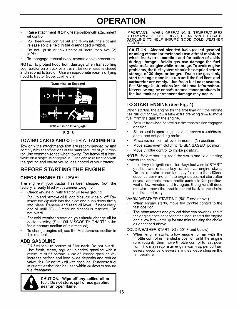
TO OPERATE MOWER (See Fig. 7)Your tractor is equipped with an operator presence sensingswitch. Any attempt by the operator to leave the seat withthe engine running and the attachment clutch engagedwill shut off the engine. You must remain fully and centrallypositioned in the seat to prevent the engine from hesitatingor cutting off when operating your equipment on rough,rolling terrain or hills.
Select desired height of cut.Start mower blades by engaging attachment clutchcontrol.
TO STOP MOWER BLADES - disengage attachmentclutch control.
CAUTION: Do not operate the mowerwithout either the entire grass catcher,on mowers so equipped, or the deflectorshield in place.
"ENGAGED" POSITIONATTACHMENT
LEVERHIGH POSITION
LOWPOSITION
ATTACHMENTCLUTCH LEVER"DISENGAGED"POSITION
DEFLECTORSHIELD
REVERSE OPERATION SYSTEM (ROS)Your tractor is equipped with a Reverse Operation System(ROS).Any attempt bythe operatortotravel in the reversedirec-tionwith the attachment clutch engaged will shut offthe engineunless ignition key is placed in the ROS "ON" position.
_I_WARNING: Backing up with the attachment clutch en-gaged wh,!le mowing is strongly discouraged. Turning theROS ON, to allow reverse operation with the attachmentclutch engaged, should only be done when the operatordecides it is necessary to reposition the machine with theattachment engaged. Do not mow in reverse unlessabsolutely necessary.
USING THE REVERSE OPERATION SYSTEM -Move motion control lever to neutral (N) position.With engine running, turn ignition key counterclockwiseto ROS "ON" position.Look down and behind before backing.Slowly move motion control lever to reverse (R) positionto start movement.
When use of the ROS is no longer needed, turn theignition key clockwise to engine "ON" position.ROS "ON" POSITION ENGINE "ON" POSITION
(NORMAL OPERATING)
TO OPERATE ON HILLS
I _ WARNING: Do not drive up or downhills with slopes greater than 15° anddo not drive across any slope.
Choose the slowest speed before starting up or downhills.
Avoid stopping or changing speed on hills.If slowing is necessary, move throttle control lever toslower position.If stopping is absolutely necessary, push clutch/brakepedal quickly to brake position and engage parkingbrake.
Move motion control lever to neutral (N) position.IMPORTANT: THE MOTIONCONTROLLEVER DOESNOTRETURNTO NEUTRAL (N) POSITIONWHEN THE CLUTCH/BRAKE PEDAL IS DEPRESSED.
To restart movement, slowly release parking brake andclutch/brake pedal.Slowly move motion control lever to slowest setting.Make all turns slowly.
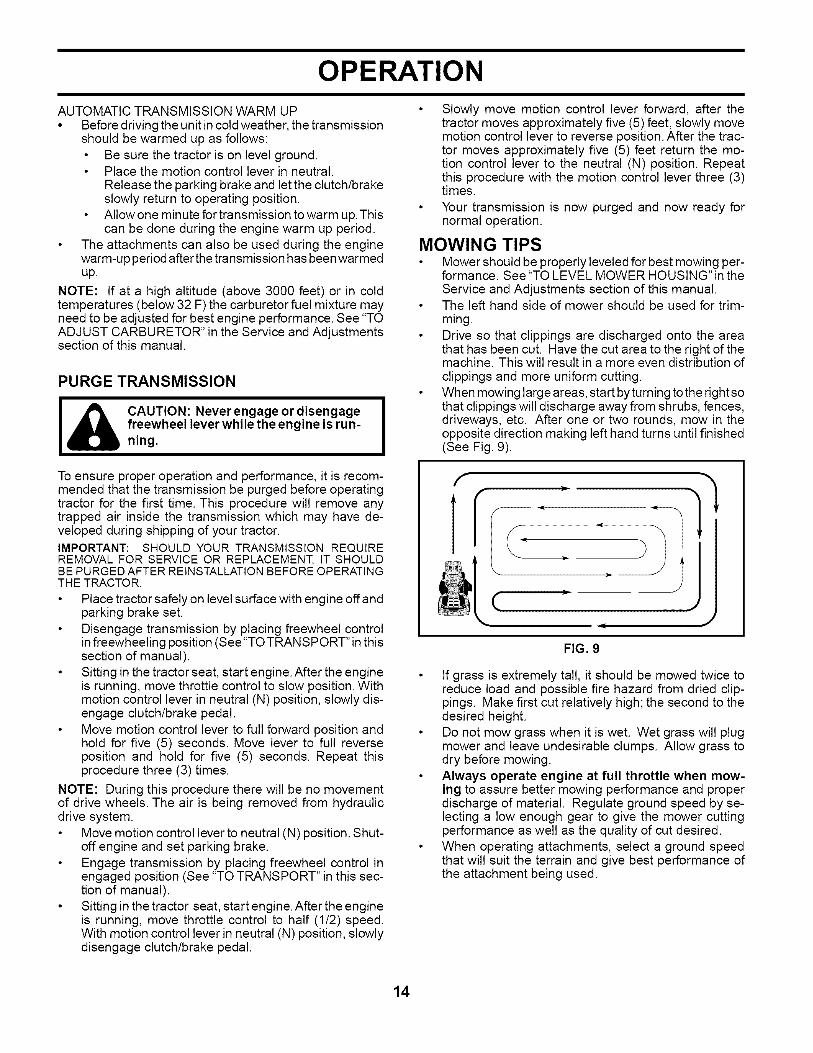
TO TRANSPORT (See Figs. 4 and 8)When pushing or towing your tractor, be sure to disengagetransmission by placing freewheel control in freewheelingposition. Free wheel control is located at the rear drawbarof tractor.
FIG. 712
OPERATION
Raise attachment lift to highest position with attachmentlift control.Pull freewheel control out and down into the slot andrelease so it is held in the disengaged position.Do not push or tow tractor at more than two (2)MPH.
To reengage transmission, reverse above procedure.
NOTE: To protect hood from damage when transportingyour tractor on a truck or a trailer, be sure hood is closedand secured to tractor. Use an appropriate means of tyinghood to tractor (rope, cord, etc.).
Transmission Engaged
Transmission Disengaged
FIG. 8
TOWING CARTS AND OTHER ATTACHMENTS
Tow only the attachments that are recommended by andcomply with specifications of the manufacturer of your trac-tor. Use common sense when towing. Too heavy of a load,while on a slope, is dangerous. Tires can lose traction withthe ground and cause you to lose control of your tractor.
BEFORE STARTING THE ENGINE
CHECK ENGINE OIL LEVEL
The engine in your tractor has been shipped, from thefactory, already filled with summer weight oil.
Check engine oil with tractor on level ground.Pull up and remove oil fill cap/dipstick; wipe oil off. Re-insert the dipstick into the tube and push down firmlyinto place. Remove and read oil level. If necessary,add oil until "FULl_:'mark on dipstick is reached. Donot overfill.For cold weather operation you should change oil foreasier starting (See "OIL VISCOSITY CHART" in theMaintenance section of this manual).To change engine oil, see the Maintenance section inthis manual.
ADD GASOLINEFill fuel tank to bottom of filler neck. Do not overfill.Use fresh, clean, regular unleaded gasoline with aminimum of 87 octane. (Use of leaded gasoline willincrease carbon and lead oxide deposits and reducevalve life). Do not mix oil with gasoline. Purchase fuelin quantities that can be used within 30 days to assurefuel freshness.
I& CAUTION: Wipe off any spilled oil or I
I
fuel. Do not store, spill or use gasoline Inear an open flame.
IMPORTANT: WHEN OPERATING IN TEMPERATURESBELOW32°F(0°C), USE FRESH, CLEAN WINTER GRADEGASOLINE TO HELP INSURE GOOD COLD WEATHERSTARTING.
CAUTION: Alcohol blended fuels (called gasoholor using ethanol or methanol) can attract moisturewhich leads to separation and formation of acidsduring storage. Acidic gas can damage the fuelsystem of an engine while instorage. To avoid engineproblems, the fuel system should be emptied beforestorage of 30 days or longer. Drain the gas tank,start the engine and let it run until the fuel lines andcarburetor are empty. Use fresh fuel next season.See Storage Instructions for additional information.Never use engine or carburetor cleaner products inthe fuel tank or permanent damage may occur.
TO START ENGINE (See Fig. 4)When starting the engine for the first time or if the enginehas run out of fuel, it will take extra cranking time to movefuel from the tank to the engine.
Be sure freewheel control is in the transmission engagedposition.Sit on seat in operating position, depress clutch/brakepedal and set parking brake.Place motion control lever in neutral (N) position.Move attachment clutch to "DISENGAGED" position.Move throttle control to choke position.
NOTE: Before starting, read the warm and cold startingprocedures below.
Insert key into ignition and turn keyclockwise to "START"position and release key as soon as engine starts.Do not run starter continuously for more than fifteenseconds per minute. If the engine does not start afterseveral attempts, move throttle control to fast position,wait a few minutes and try again. If engine still doesnot start, move the throttle control back to the chokeposition and retry.
WARM WEATHER STARTING (50° F and above)When engine starts, move the throttle control to thefast position.The attachments and ground drive can now be used. Ifthe engine does not accept the load, restart the engineand allow it to warm up for one minute using the chokeas described above.
COLD WEATHER STARTING ( 50° F and below)When engine starts, allow engine to run with thethrottle control in the choke position until the engineruns roughly, then move throttle control to fast posi-tion. This may require an engine warm-up period fromseveral seconds to several minutes, depending on thetemperature.
13
OPERATION
AUTOMATIC TRANSMISSION WARM UP• Before driving the unit in cold weather, the transmission
should be warmed up as follows:Be sure the tractor is on level ground.Place the motion control lever in neutral.Release the parking brake and let the clutch/brakeslowly return to operating position.Allow one minute for transmission to warm up. Thiscan be done during the engine warm up period.
The attachments can also be used during the enginewarm-up period afterthe transmission has been warmedup.
NOTE: If at a high altitude (above 3000 feet) or in coldtemperatures (below 32 F) the carburetor fuel mixture mayneed to be adjusted for best engine performance. See "TOADJUST CARBURETOR" in the Service and Adjustmentssection of this manual.
PURGE TRANSMISSION
I_lb AUTION: Neverengageordisengage Ifreewheel lever while the engine is run-ning.
To ensure proper operation and performance, it is recom-mended that the transmission be purged before operatingtractor for the first time. This procedure will remove anytrapped air inside the transmission which may have de-veloped during shipping of your tractor.IMPORTANT: SHOULD YOUR TRANSMISSION REQUIREREMOVALFOR SERVICE OR REPLACEMENT, IT SHOULDBEPURGEDAFTER REINSTALLATIONBEFOREOPERATINGTHE TRACTOR.
Place tractor safely on level surface with engine off andparking brake set.Disengage transmission by placing freewheel controlin freewheeling position (See "TO TRANSPORT" in thissection of manual).Sitting in the tractor seat, start engine. After the engineis running, move throttle control to slow position. Withmotion control lever in neutral (N) position, slowly dis-engage clutch/brake pedal.Move motion control lever to full forward position andhold for five (5) seconds. Move lever to full reverseposition and hold for five (5) seconds. Repeat thisprocedure three (3) times.
NOTE: During this procedure there will be no movementof drive wheels. The air is being removed from hydraulicdrive system.
Move motion control lever to neutral (N) position. Shut-off engine and set parking brake.Engage transmission by placing freewheel control inengaged position (See "TO TRANSPORT" in this sec-tion of manual).Sitting in the tractor seat, start engine. After the engineis running, move throttle control to half (1/2) speed.With motion control lever in neutral (N) position, slowlydisengage clutch/brake pedal.
Slowly move motion control lever forward, after thetractor moves approximately five (5) feet, slowly movemotion control lever to reverse position. After the trac-tor moves approximately five (5) feet return the mo-tion control lever to the neutral (N) position. Repeatthis procedure with the motion control lever three (3)times.Your transmission is now purged and now ready fornormal operation.
MOWING TIPSMower should be properly leveled for best mowing per-formance. See "TO LEVEL MOWER HOUSING" in theService and Adjustments section of this manual.The left hand side of mower should be used for trim-ming.Drive so that clippings are discharged onto the areathat has been cut. Have the cut area to the right of themachine. This will result in a more even distribution ofclippings and more uniform cutting.When mowing large areas, start by turning tothe right sothat clippings will discharge away from shrubs, fences,driveways, etc. After one or two rounds, mow in theopposite direction making left hand turns until finished(See Fig. 9).
FIG. 9
If grass is extremely tall, it should be mowed twice toreduce load and possible fire hazard from dried clip-pings. Make first cut relatively high; the second to thedesired height.Do not mow grass when it is wet. Wet grass will plugmower and leave undesirable clumps. Allow grass todry before mowing.Always operate engine at full throttle when mow-ing to assure better mowing performance and properdischarge of material. Regulate ground speed by se-lecting a low enough gear to give the mower cuttingperformance as well as the quality of cut desired.When operating attachments, select a ground speedthat will suit the terrain and give best performance ofthe attachment being used.
14
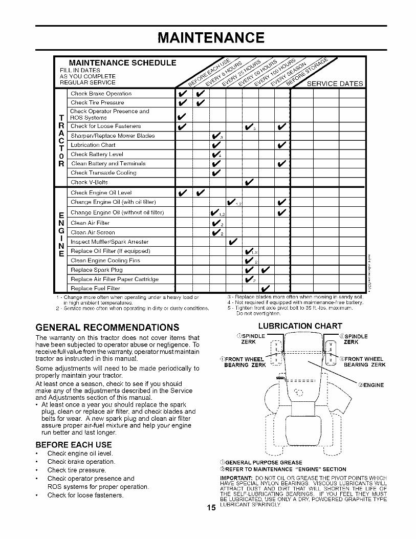
MAINTENANCE
MA,NTENANCESCHEDULE "F,LL, O TESAS YOU COMPLETE ._'__ ..-.._.O"_,'_........... -R EGU LAR SERVICE V,OEOATES
Check Brake Operation I_ t_Check Tire Pressure
Check Operator Presence andT ROS Systems V'
R Check for Loose Fasteners I1_ 1_5 I_
A Sharpen/Replace Mower Blades 111_3
C Lubrication Chart _ If0 Check Battery Level
R Clean Battery and Terminals I_
Check Transaxle Cooling if
Check V-Belts If
Check Engine Oil Level li_ if
Change Engine Oil (with oil filter) 11_1,2
E Change Engine Oil (without oil filter) QI_I, 2
N Clean Air Filter 1_2
G Clean Air Screen 1_2
Inspect Muffler/Spark Arrester t/E Replace Oil Filter (If equipped) 1_,2
Clean Engine Cooling Fins If 2
Replace Spark Plug if If
I/2Replace Air Filter Paper Cartridge
Replace Fuel Filter I1_
1 - Change more often when operating under a heavy load orin high ambient temperatures.
2 - Service more often when operating in dirty or dusty conditions.
3 - Replace blades more often when mowing in sandy soil.4 - Not required if equipped with maintenance-free battery.5 - Tighten front axle pivot bolt to 35 ft,-Ibs, maximum.
Do not overtighten,
GENERAL RECOMMENDATIONSThe warranty on this tractor does not cover items thathave been subjected to operator abuse or negligence. Toreceive full value from the warranty, operator must maintaintractor as instructed in this manual.
Some adjustments will need to be made periodically toproperly maintain your tractor.At least once a season, check to see if you shouldmake any of the adjustments described in the Serviceand Adjustments section of this manual.• At least once a year you should replace the spark
plug, clean or replace air filter, and check blades andbelts for wear. A new spark plug and clean air filterassure proper air-fuel mixture and help your enginerun better and last longer.
BEFORE EACH USECheck engine oil level.Check brake operation.Check tire pressure.Check operator presence andROS systems for proper operation.Check for loose fasteners.
LUBRICATION CHART_)SPINDLE
ZERK _ _r"", ZERK
Z
_FRONT WHEEL I I} "d_FRONT WHEELBEARING ZERK BEARING ZERK
@ENGINE
_)GENERAL PURPOSE GREASE@REFER TO MAINTENANCE "ENGINE" SECTION
IMPORTANT: DO NOT OIL OR GREASE THE PIVOT POINTS WHICHHAVE SPECIAL NYLON BEARINGS. VISCOUS LUBRICANTS WILLATTRACT DUST AND DIRT THAT WILL SHORTEN THE LIFE OFTHE SELF-LUBRICATING BEARINGS. IF YOU FEEL THEY MUSTBE LUBRICATED, USE ONLY A DRY, POWDERED GRAPHITE TYPE
15 LUBRICANTSPARINGLY.
MAINTENANCE
TRACTORAlways observe safety rules when performing any main-tenance.
BRAKE OPERATION
If tractor requires more than five (5) feet to stop at highestspeed in highest gear on a level, dry concrete or pavedsurface, then brake must be checked and adjusted. (See"TO ADJUST BRAKE" in the Service and Adjustmentssection of this manual).
TIRESMaintain proper air pressure inall tires (See"PRODUCTSPECIFICATIONS" section of this manual).Keep tires free of gasoline, oil, or insect control chemi-cals which can harm rubber.
Avoid stumps, stones, deep ruts, sharp objects andother hazards that may cause tire damage.
NOTE: To seal tire punctures and prevent flat tires due toslow leaks, tire sealant may be purchased from your localparts dealer. Tire sealant also prevents tire dry rot andcorrosion.
OPERATOR PRESENCE SYSTEM AND REVERSE OP-ERATION SYSTEM (ROS)Be sure operator presence and reverse operation systemsare working properly. If your tractor does not function asdescribed, repair the problem immediately.
The engine should not start unless the brake pedal isfully depressed, and the attachment clutch control isin the disengaged position.
CHECK OPERATOR PRESENCE SYSTEMWhen the engine is running, any attempt by the operatorto leave the seat without first setting the parking brakeshould shut off the engine.When the engine is running and the attachment clutchis engaged, any attempt by the operator to leave theseat should shut off the engine.The attachment clutch should never operate unlessthe operator is in the seat.
CHECK REVERSE OPERATION (ROS) SYSTEMWhen the engine is running with the ignition switch inthe engine "ON" position and the attachment clutchengaged, any attempt by the operator to shift intoreverse should shut off the engine.When the engine is running with the ignition switch inthe ROS "ON" position and the attachment clutch en-gaged, any attempt by the operator to shift into reverseshould NOT shut off the engine.
ROS "ON" POSITION ENGINE "ON" POSITION(NORMAL OPERATING)
BLADE CARE
For best results mower blades must be kept sharp. Replacebent or damaged blades.
_ CAUTION: Useonlya replacement blade
approved by the manufacturer of yourtractor. Using a blade not approvedby the manufacturer of your tractor ishazardous, could damage your tractorand void your warranty.
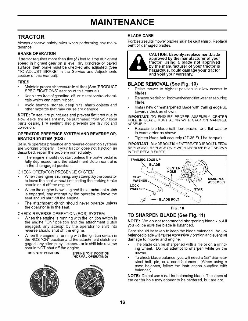
BLADE REMOVAL (See Fig. 10)Raise mower to highest position to allow access toblades.
Remove blade bolt, Iockwasher and flatwasher securingblade.Install new or resharpened blade with trailing edge uptowards deck as shown.
IMPORTANT: TO ENSURE PROPER ASSEMBLY, CENTERHOLE IN BLADE MUST ALIGN WITH STAR ON MANDRELASSEMBLY.
Reassemble blade bolt, lock washer and flat washerin exact order as shown.
Tighten blade bolt securely (27-35 Ft. Lbs. torque).
IMPORTANT: BLADE BOLT IS HEATTREATED.IF BOLT NEEDSREPLACING, REPLACE ONLY WITH APPROVE BOLT SHOWNIN THE REPAIR PARTS.
TRAILING EDGE UP
BLADE
FLAT
CENTERHOLE
LOCK
WASHER_r @
_BLADE BOLT
STAR
MANDRELASSEMBLY
FIG. 10
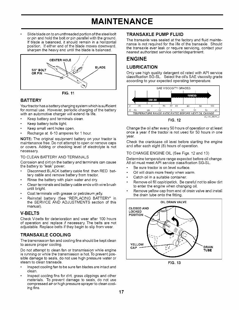
TO SHARPEN BLADE (See Fig. 11)NOTE: We do not recommend sharpening blade - but ifyou do, be sure the blade is balanced.
Care should be taken to keep the blade balanced. An un-balanced blade will cause excessive vibration and eventualdamage to mower and engine.
The blade can be sharpened with a file or on a grind-ing wheel. Do not attempt to sharpen while on themower.
To check blade balance, you will need a 5/8" diametersteel bolt, pin, or a cone balancer. (When using acone balancer, follow the instructions supplied withbalancer).
NOTE: Do not use a nail for balancing blade. The lobes ofthe center hole may appear to be centered, but are not.
16
MAINTENANCE
Slide blade on to an unthreaded portion of the steel boltor pin and hold the bolt or pin parallel with the ground.If blade is balanced, it should remain in a horizontalposition. If either end of the blade moves downward,sharpen the heavy end until the blade is balanced.
CENTER HOLE
BLADE
5/8" BOLTOR PIN
FIG. 11
BATTERY
Yourtractor has a battery charging system which is sufficientfor normal use. However, periodic charging of the batterywith an automotive charger will extend its life.
Keep battery and terminals clean.Keep battery bolts tight.Keep small vent holes open.Recharge at 6-10 amperes for 1 hour.
NOTE: The original equipment battery on your tractor ismaintenance free. Do not attempt to open or remove capsor covers. Adding or checking level of electrolyte is notnecessary.
TO CLEAN BATTERY AND TERMINALS
Corrosion and dirt on the battery and terminals can causethe battery to "leak" power.
Disconnect BLACK battery cable first then RED bat-tery cable and remove battery from tractor.Rinse the battery with plain water and dry.Clean terminals and battery cable ends with wire brushuntil bright.Coat terminals with grease or petroleum jelly.Reinstall battery (See "REPLACING BATTERY" inthe SERVICE AND ADJUSTMENTS section of thismanual).
V-BELTSCheck V-belts for deterioration and wear after 100 hoursof operation and replace if necessary. The belts are notadjustable. Replace belts if they begin to slip from wear.
TRANSAXLE COOLING
The transmission fan and cooling fins should be kept cleanto assure proper cooling.
Do not attempt to clean fan or transmission while engineis running or while the transmission is hot. To prevent pos-sible damage to seals, do not use high pressure water orsteam to clean transaxle.
Inspect cooling fan to be sure fan blades are intact andclean.Inspect cooling fins for dirt, grass clippings and othermaterials. To prevent damage to seals, do not usecompressed air or high pressure sprayer to clean cool-ing fins.
TRANSAXLE PUMP FLUID
The transaxle was sealed at the factory and fluid mainte-nance is not required for the life of the transaxle. Shouldthe transaxle ever leak or require servicing, contact yournearest authorized service center/department.
ENGINE
LUBRICATION
Only use high quality detergent oil rated with API serviceclassification SG-SL. Select the oil's SAE viscosity gradeaccording to your expected operating temperature.
SAE VISCOSITY GRADES
IE£ I,E,q
F -20 0 30 32 40 60 80 100
c -_0 -2; -1; ; 1'0 _0 10TEMPERATURE RANGE ANTICIPATED BEFORE NEXT OIL CHANGE
oilvisc chart4 e
FIG. 12
Change the oil after every 50 hours of operation or at leastonce a year if the tractor is not used for 50 hours in oneyear.
Check the crankcase oil level before starting the engineand after each eight (8) hours of operation.
TO CHANGE ENGINE OIL (See Figs. 12 and 13)
Determine temperature range expected before oil change.All oil must meet API service classification SG-SL.
Be sure tractor is on level surface.
Oil will drain more freely when warm.Catch oil in a suitable container.
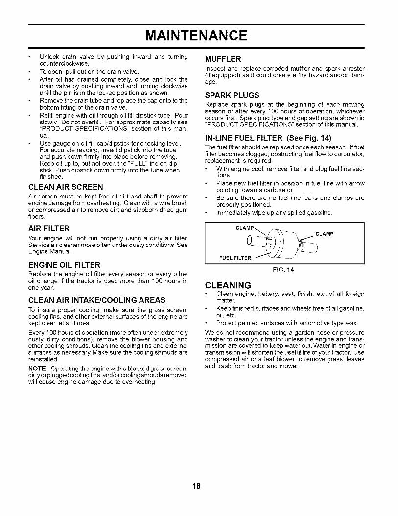
Remove oil fill cap/dipstick. Be careful not to allow dirtto enter the engine when changing oil.Remove yellow cap from end of drain valve and installthe drain tube onto the fitting.
OIL DRAIN VALVE
CLOSED AND _
LOCKED _ ! "_.
POSITION_ _
////_
YELLOW k-_ ._ _..,,_
CAP _'\ _ :_ . / _" y - DRAIN
-_ TUBE
FIG. 13
17
MAINTENANCE
Unlock drain valve by pushing inward and turningcounterclockwise.To open, pull out on the drain valve.After oil has drained completely, close and lock thedrain valve by pushing inward and turning clockwiseuntil the pin is in the locked position as shown.Remove the drain tube and replace the cap onto to thebottom fitting of the drain valve.Refill engine with oil through oil fill dipstick tube. Pourslowly. Do not overfill. For approximate capacity see"PRODUCT SPECIFICATIONS" section of this man-ual.
Use gauge on oil fill cap/dipstick for checking level.For accurate reading, insert dipstick into the tubeand push down firmly into place before removing.Keep oil up to, but not over, the "FULL' line on dip-stick. Push dipstick down firmly into the tube whenfinished.
CLEAN AIR SCREEN
Air screen must be kept free of dirt and chaff to preventengine damage from overheating. Clean with a wire brushor compressed air to remove dirt and stubborn dried gumfibers.
AIR FILTER
Your engine will not run properly using a dirty air filter.Service air cleaner more often under dusty conditions. SeeEngine Manual.
ENGINE OIL FILTER
Replace the engine oil filter every season or every otheroil change if the tractor is used more than 100 hours inone year.
CLEAN AIR INTAKE/COOLING AREAS
To insure proper cooling, make sure the grass screen,cooling fins, and other external surfaces of the engine arekept clean at all times.
Every 100 hours of operation (more often under extremelydusty, dirty conditions), remove the blower housing andother cooling shrouds. Clean the cooling fins and externalsurfaces as necessary. Make sure the cooling shrouds arereinstalled.
NOTE: Operating the engine with a blocked grass screen,dirty or plugged cooling fins, and/or cooling shrouds removedwill cause engine damage due to overheating.
MUFFLER
Inspect and replace corroded muffler and spark arrester(if equipped) as it could create a fire hazard and/or dam-age.
SPARK PLUGS
Replace spark plugs at the beginning of each mowingseason or after every 100 hours of operation, whicheveroccurs first. Spark plug type and gap setting are shown in"PRODUCT SPECIFICATIONS" section of this manual.
IN-LINE FUEL FILTER (See Fig. 14)The fuel filter should be replaced once each season. If fuelfilter becomes clogged, obstructing fuel flow to carburetor,replacement is required.
With engine cool, remove filter and plug fuel line sec-tions.
Place new fuel filter in position in fuel line with arrowpointing towards carburetor.Be sure there are no fuel line leaks and clamps areproperly positioned.Immediately wipe up any spilled gasoline.
CLAMP_ _
FUEL FILTER _'-
FIG. 14
CLEANINGClean engine, battery, seat, finish, etc. of all foreignmatter.
Keep finished surfaces and wheels free of all gasoline,oil, etc.Protect painted surfaces with automotive type wax.
We do not recommend using a garden hose or pressurewasher to clean your tractor unless the engine and trans-mission are covered to keep water out. Water in engine ortransmission will shorten the useful life of your tractor. Usecompressed air or a leaf blower to remove grass, leavesand trash from tractor and mower.
18

SERVICE AND ADJUSTMENTS
WARNING: TO AVOID SERIOUS INJURY, BEFORE PERFORMING ANY SERVICE OR ADJUST-MENTS:
Depress clutch/brake pedal fully and set parking brake.Place motion control lever in neutral (N) position.Place attachment clutch in "DISENGAGED" position.Turn ignition key to "STOP" and remove key.Make sure the blades and all moving parts have completely stopped.Disconnect spark plug wire from spark plug and place wire where it cannot come in contactwith plug.
TRACTOR
TO REMOVE MOWER (See Fig. 15)Mower will be easier to remove from the right side of trac-tor.
Place attachment clutch in "DISENGAGED" position.Move attachment lift lever forward to lower mower toits lowest position.Roll belt off engine pulley.Remove small retainer spring, and remove clutch springoff pulley bolt.Remove large retainer spring, slide collar off and pushhousing guide out of bracket.Disconnect anti-swaybar from chassis bracket by re-moving retainer spring.Disconnect suspension arms from rear deck bracketsby removing retainer springs.Disconnect front links from deck by removing retainersprings.Raise lift lever to raise suspension arms. Slide mowerout from under tractor.
IMPORTANT: IF AN ATTACHMENT OTHERTHAN THE MOWERDECK ISTO BE MOUNTED ON THE TRACTOR, REMOVE THEFRONT LINKSAND HOOKTHE CLUTCH SPRING INTO SQUAREHOLE IN FRAME.
TO INSTALL MOWER (See Fig. 15)Raise attachment lift lever to its highest position.Slide mower under tractor with deflector shield to rightside of tractor.Lower lift lever to its lowest position.Connect front links to mower deck and secure withretainer springs..Connect suspension arms to rear deck brackets andsecure with retainer springs.Connect anti-swaybar to chassis bracket and securewith retainer spring.Push clutch cable housing guide into bracket, slide col-lar onto guide and secure with large retainer spring.Place flat washer and clutch spring on idler pulley boltand secure with small retainer spring.Install belt onto engine pulley.
TO LEVEL MOWER HOUSING
Adjust the mower while tractor is parked on level groundor driveway. Make sure tires are properly inflated (See"PRODUCT SPECIFICATIONS'section of this manual). Iftires are over or underinflated, you will not properly adjustyour mower.
SMALL RETAINER SPRING
CLUTCH SPRING
SMALL RETAINER SPRING
CLUTCH SPRING
ENGINE PULLEY
FRONT LINK
COLLAR
RETAINER SPRINGS
(BOTH SIDES)
HOUSING GUIDELARGE RETAINERSPRING
BRACKETDEFLECTOR SHIELD
FIG. 15
19
SERVICE AND ADJUSTMENTS
SIDE-TO-SIDE ADJUSTMENT (See Figs. 16 and 17)Raise mower to its highest position.At the midpoint of both sides of mower, measure heightfrom bottom edge of mower to ground. Distance "A"on both sides of mower should be the same or within1/4" of each other.
If adjustment is necessary, make adjustment on oneside of mower only.To raise one side of mower, tighten lift link adjustmentnut on that side.
To lower one side of mower, loosen lift link adjustmentnut on that side.
NOTE: Three full turns ofadjustment nutwill change mowerheight about 1/8".
Recheck measurements after adjusting.
BOTTOM EDGE OF BOTTOM EDGEMOWER F q --qOFMOWER
7 GROUNDL=EFIG. 16
_\ SUSPENSION ARM
c--',3 /
LIFT LINKADJUS_ "
FIG. 17
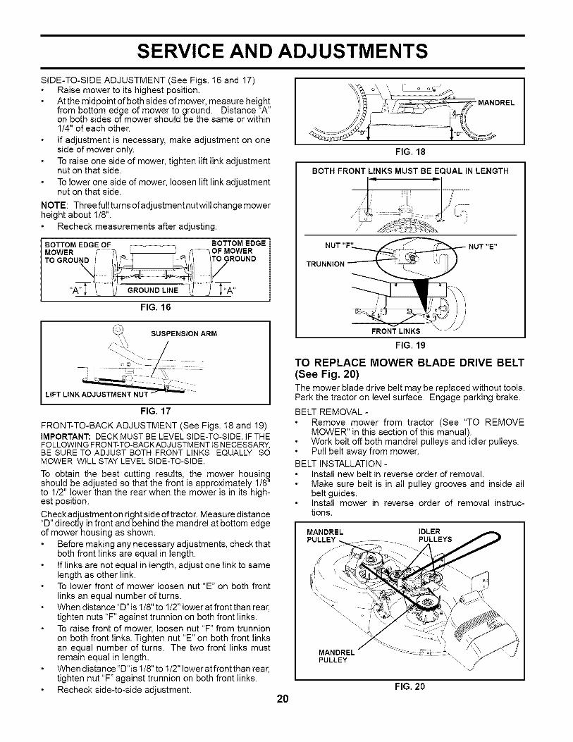
FRONT-TO-BACK ADJUSTMENT (See Figs. 18 and 19)IMPORTANT: DECK MUST BE LEVEL SIDE-TO-SIDE. IF THEFOLLOWING FRONT-TO-BACKADJ USTMENT IS NECESSARY,BE SURE TO ADJUST BOTH FRONT LINKS EQUALLY SOMOWER WILL STAY LEVEL SIDE-TO-SIDE
To obtain the best cutting results, the mower housingshould be adjusted so that the front is approximately 1/8"to 1/2" lower than the rear when the mower is in its high-est position.
Check adjustment on right side of tractor. Measure distance"D" directly in front and behind the mandrel at bottom edgeof mower housing as shown.
Before making any necessary adjustments, check thatboth front links are equal in length.If links are not equal in length, adjust one link to samelength as other link.To lower front of mower loosen nut "E" on both frontlinks an equal number of turns.When distance "D" is 1/8" to 1/2" lower at front than rear,tighten nuts "F" against trunnion on both front links.To raise front of mower, loosen nut "F" from trunnionon both front links. Tighten nut "E" on both front linksan equal number of turns. The two front links mustremain equal in length.When distance "D"is 1/8" to 1/2" lower at front than rear,tighten nut "F" against trunnion on both front links.Recheck side-to-side adjustment.
FIG. 18
BOTH FRONT LINKS MUST BE EQUAL IN LENGTH
NUT "F'
TRUNNION
NUT "E"
FRONT LINKS
FIG. 19
TO REPLACE MOWER BLADE DRIVE BELT(See Fig. 20)The mower blade drive belt may be replaced without tools.Park the tractor on level surface. Engage parking brake.
BELT REMOVAL -Remove mower from tractor (See "TO REMOVEMOWER" in this section of this manual).Work belt off both mandrel pulleys and idler pulleys.Pull belt away from mower.
BELT INSTALLATION -Install new belt in reverse order of removal.Make sure belt is in all pulley grooves and inside allbelt guides.Install mower in reverse order of removal instruc-tions.
MANDREL IDLERPULLEYS
MANDRELPULLEY
20FIG. 20
SERVICE AND ADJUSTMENTS
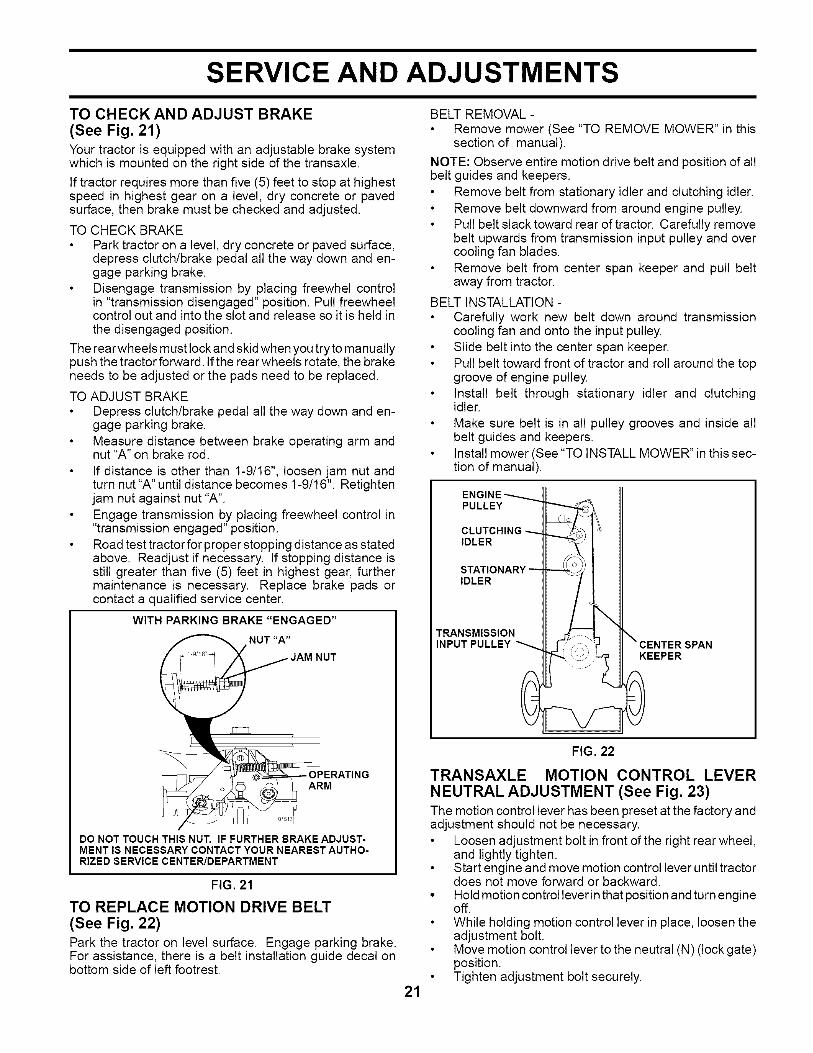
TO CHECKAND ADJUST BRAKE(See Fig. 21)Your tractor is equipped with an adjustable brake systemwhich is mounted on the right side of the transaxle.
If tractor requires more than five (5) feet to stop at highestspeed in highest gear on a level, dry concrete or pavedsurface, then brake must be checked and adjusted.
TO CHECK BRAKEPark tractor on a level, dry concrete or paved surface,depress clutch/brake pedal all the way down and en-gage parking brake.Disengage transmission by placing freewhel controlin "transmission disengaged" position. Pull freewheelcontrol out and into the slot and release so it is held inthe disengaged position.
The rear wheels must lock and skid when you try to manuallypush the tractor forward. If the rear wheels rotate, the brakeneeds to be adjusted or the pads need to be replaced.
TO ADJUST BRAKEDepress clutch/brake pedal all the way down and en-gage parking brake.Measure distance between brake operating arm andnut "A" on brake rod.
If distance is other than 1-9/16", loosen jam nut andturn nut "A" until distance becomes 1-9/16". Retightenjam nut against nut "A".Engage transmission by placing freewheel control in"transmission engaged" position.Road test tractor for proper stopping distance as statedabove. Readjust if necessary. If stopping distance isstill greater than five (5) feet in highest gear, furthermaintenance is necessary. Replace brake pads orcontact a qualified service center.
WITH PARKING BRAKE"ENGAGED"
NUT
ARM
DO NOT TOUCH THIS NUT. IF FURTHER BRAKE ADJUST-MENT IS NECESSARY CONTACT YOUR NEAREST AUTHO-RIZED SERVICE CENTER/DEPARTMENT
FIG. 21
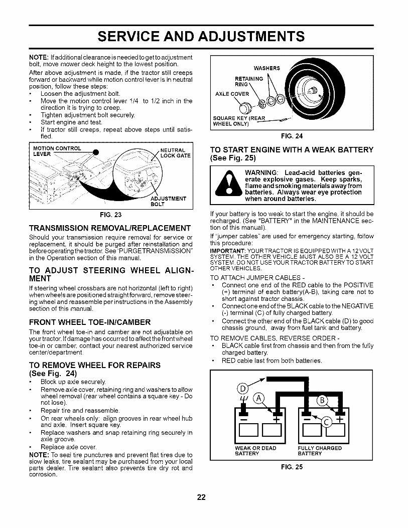
TO REPLACE MOTION DRIVE BELT
(See Fig. 22)Park the tractor on level surface. Engage parking brake.For assistance, there is a belt installation guide decal onbottom side of left footrest.
BELT REMOVAL -Remove mower (See "TO REMOVE MOWER" in thissection of manual).
NOTE: Observe entire motion drive belt and position of allbelt guides and keepers.
Remove belt from stationary idler and clutching idler.Remove belt downward from around engine pulley.Pull belt slack toward rear of tractor. Carefully removebelt upwards from transmission input pulley and overcooling fan blades.Remove belt from center span keeper and pull beltaway from tractor.
BELT INSTALLATION -Carefully work new belt down around transmissioncooling fan and onto the input pulley.Slide belt into the center span keeper.Pull belt toward front of tractor and roll around the topgroove of engine pulley.Install belt through stationary idler and clutchingidler.
Make sure belt is in all pulley grooves and inside allbelt guides and keepers.Install mower (See "TO INSTALL MOWER" in this sec-tion of manual).
ENGINE_PULLEY
CLUTCHING ---.,-.IDLER
STATIONARYIDLER
TRANSMISSIONINPUT PULLEY
KEEPER
21
FIG. 22
TRANSAXLE MOTION CONTROL LEVERNEUTRAL ADJUSTMENT (See Fig. 23)The motion control lever has been preset at the factory andadjustment should not be necessary.
Loosen adjustment bolt in front of the right rear wheel,and lightly tighten.Start engine and move motion control lever until tractordoes not move forward or backward.
• Hold motion control lever in that position and turn engineoff.
While holding motion control lever in place, loosen theadjustment bolt.Move motion control lever to the neutral (N) (lock gate)position.Tighten adjustment bolt securely.
SERVICE AND ADJUSTMENTS
NOTE: Ifadditional clearance is needed to get to adjustmentbolt, move mower deck height to the lowest position.After above adjustment is made, if the tractor still creepsforward or backward while motion control lever is in neutralposition, follow these steps:
Loosen the adjustment bolt.Move the motion control lever 1/4 to 1/2 inch in thedirection it is trying to creep.Tighten adjustment bolt securely.Start engine and test.If tractor still creeps, repeat above steps until satis-fied.
MOTION CONTROL ,NEUTRALLEVER LOCK GATE
s
....... ADJUSTMENTBOLT
FIG. 23
TRANSMISSION REMOVAL/REPLACEMENT
Should your transmission require removal for service orreplacement, it should be purged after reinstallation andbefore operating the tractor. See"PURGETRANSMISSION"in the Operation section of this manual,
TO ADJUST STEERING WHEEL ALIGN-MENT
If steering wheel crossbars are not horizontal (left to right)whenwheelsare positioned straightforward, remove steer-ing wheel and reassemble per instructions in the Assemblysection of this manual.
FRONT WHEEL TOE-IN/CAMBER
The front wheel toe-in and camber are not adjustable onyour tractor. Ifdamage has occurred to affect the front wheeltoe-in or camber, contact your nearest authorized servicecenter/department.
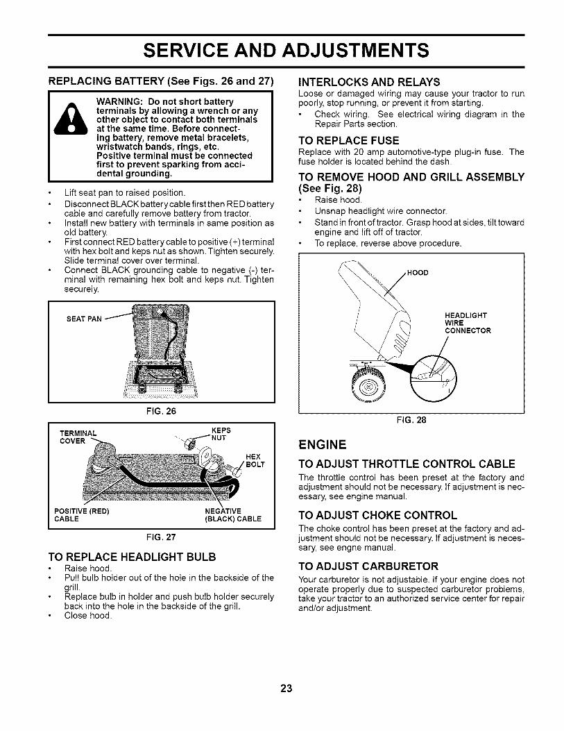
TO REMOVE WHEEL FOR REPAIRS(See Fig. 24)
Block up axle securely.Remove axle cover, retaining ring and washers to allowwheel removal (rear wheel contains a square key - Donot lose).Repair tire and reassemble.On rear wheels only: align grooves in rear wheel huband axle. Insert square key.Replace washers and snap retaining ring securely inaxle groove.Replace axle cover.
NOTE: To seal tire punctures and prevent flat tires due toslow leaks, tire sealant may be purchased from your localparts dealer. Tire sealant also prevents tire dry rot andcorrosion.
WASHERS
RETAINING
AXLE COVER
SQUARE KEY(REAR_............_ _i WHEEL ONLY)
FIG. 24
TO START ENGINE WITHAWEAK BATTERY(See Fig. 25)
WARNING: Lead-acid batteries gen-erate explosive gases. Keep sparks,flame and smoking materials away frombatteries. Always wear eye protectionwhen around batteries.
If your battery is too weak to start the engine, it should berecharged. (See "BATTERY" in the MAINTENANCE sec-tion of this manual).If "jumper cables" are used for emergency starting, followthis procedure:IMPORTANT:YOURTRACTORIS EQUIPPEDWITHA 12VOLTSYSTEM.THE OTHERVEHICLE MUST ALSO BE A 12VOLTSYSTEM.DO NOTUSEYOURTRACTORBATTERYTO STARTOTHERVEHICLES.
TO ATTACH JUMPER CABLES -Connect one end of the RED cable to the POSITIVE(+) terminal of each battery(A-B), taking care not toshort against tractor chassis.Connect one end of the BLACK cable to the NEGATIVE(-) terminal (C) of fully charged battery.Connect the other end of the BLACK cable (D) to goodchassis ground, away from fuel tank and battery.
TO REMOVE CABLES, REVERSE ORDER-BLACK cable first from chassis and then from the fullycharged battery.RED cable last from both batteries.
DDWEAK OR DEADBATTERY
FULLY CHARGEDBATTERY
FIG. 25
22
SERVICE AND ADJUSTMENTS
REPLACING BATTERY (See Figs. 26 and 27
A WARNING: Do not short batteryterminals by allowing a wrench or anyother object to contact both terminalsat the same time. Before connect-ing battery, remove metal bracelets,wristwatch bands, rings, etc.Positive terminal must be connectedfirst to prevent sparking from acci-dental grounding.
Lift seat pan to raised position.Disconnect BLACK battery cable first then RED batterycable and carefully remove battery from tractor.Install new battery with terminals in same position asold battery.First connect RED battery cable to positive (+) terminalwith hex bolt and keps nut as shown. Tighten securely.Slide terminal cover over terminal.Connect BLACK grounding cable to negative (-) ter-minal with remaining hex bolt and keps nut. Tightensecurely.
SEAT PAN
TERMINALCOVER
FIG. 26
KEPS
_NUT
HEX
POSITIVE (RED) NEGATIVECABLE (BLACK) CABLE
FIG. 27
TO REPLACE HEADLIGHT BULBRaise hood.Pull bulb holder out of the hole in the backside of thegrill.Replace bulb in holder and push bulb holder securelyback into the hole in the backside of the grill.Close hood.
INTERLOCKS AND RELAYSLoose or damaged wiring may cause your tractor to runpoorly, stop running, or prevent it from starting.
Check wiring. See electrical wiring diagram in theRepair Parts section.
TO REPLACE FUSEReplace with 20 amp automotive-type plug-in fuse. Thefuse holder is located behind the dash.
TO REMOVE HOOD AND GRILL ASSEMBLY(See Fig. 28)
Raise hood.Unsnap headlight wire connector.Stand in front of tractor. Grasp hood at sides, tilt towardengine and lift off of tractor.To replace, reverse above procedure.
HOOD
HEADLIGHTWIRECONNECTOR
FIG. 28
ENGINE
TO ADJUST THROTTLE CONTROL CABLE
The throttle control has been preset at the factory andadjustment should not be necessary. If adjustment is nec-essary, see engine manual.
TO ADJUST CHOKE CONTROL
The choke control has been preset at the factory and ad-justment should not be necessary. If adjustment is neces-sary, see engne manual.
TO ADJUST CARBURETOR
Your carburetor is not adjustable. If your engine does notoperate properly due to suspected carburetor problems,take your tractor to an authorized service center for repairand/or adjustment.
23
STORAGE
Immediately prepare your tractor for storage at the endof the season or if the tractor will not be used for 30 daysor more.
_) WARNING: Never store the tractor withgasoline in the tank inside a buildingwhere fumes may reach an open flameors park. Allow the engine to cool beforestoring in any enclosure.
TRACTORRemove mower from tractor for winter storage. When moweristo be stored for a period of time, clean it thoroughly, removeall dirt, grease, leaves, etc. Store in a clean, dry area.
Clean entire tractor (See "CLEANING" in the Mainte-nance section of this manual).Inspect and replace belts, if necessary (See belt re-placement instructions in the Service and Adjustmentssection of this manual).Lubricate as shown in the Maintenance section of thismanual.
Be sure that all nuts, bolts and screws are securelyfastened. Inspect moving parts for damage, breakageand wear. Replace if necessary.Touch up all rusted or chipped paint surfaces; sandlightly before painting.
BATTERYFully charge the battery for storage.After a period of time in storage, battery may requirerecharging.To help prevent corrosion and power leakage duringlong periods of storage, battery cables should be dis-connected and battery cleaned thoroughly (see "TOCLEAN BATTERY AND TERMINALS" in the Mainte-nance section of this manual).After cleaning, leave cables disconnected and placecables where they cannot come in contact with batteryterminals.
If battery is removed from tractor for storage, do notstore battery directly on concrete or damp surfaces.
ENGINE
FUEL SYSTEMIMPORTANT: IT IS IMPORTANTTO PREVENT GUM DEPOSITSFROM FORMING IN ESSENTIAL FUEL SYSTEM PARTS SUCHAS CARBURETOR, FUEL FILTER, FUEL HOSE, OR TANKDURING STORAGE. ALSO, EXPERIENCE INDICATES THATALCOHOL BLENDED FUELS (CALLED GASOHOL OR USINGETHANOL OR METHANOL) CAN ATTRACT MOISTURE WHICHLEADS TO SEPARATION AND FORMATION OF ACIDS DURINGSTORAGE. ACIDIC GAS CAN DAMAGE THE FUEL SYSTEMOF AN ENGINE WHILE IN STORAGE.
Empty the fuel tank by starting the engine and let it rununtil the fuel lines and carburetor are empty.Never use engine or carburetor cleaner products in thefuel tank or permanent damage may occur.Use fresh fuel next season.
NOTE: Fuel stabilizer is an acceptable alternative in mini-mizing the formation of fuel gum deposits during storage.Add stabilizer to gasoline in fuel tank or storage container.Always follow the mix ratio found on stabilizer container.Run engine at least 10 minutes after adding stabilizer toallow the stabilizer to reach the carburetor. Do not emptythe gas tank and carburetor if using fuel stabilizer.
ENGINE OIL
Drain oil (with engine warm) and replace with clean en-gine oil. (See "ENGINE" in the Maintenance section ofthis manual).
CYLINDER(S)Remove spark plug(s).Pour one ounce of oil through spark plug hole(s) intocylinder(s).Turn ignition key to "START" position for a few secondsto distribute oil.
Replace with new spark plug(s).
OTHERDo not store gasoline from one season to another.Replace your gasoline can if your can starts to rust.Rust and/or dirt in your gasoline will cause problems.If possible, store your tractor indoors and cover it togive protection from dust and dirt.Cover your tractor with a suitable protective cover thatdoes not retain moisture. Do not use plastic. Plasticcannot breathe which allows condensation to form andwill cause your tractor to rust.
IMPORTANT: NEVERCOVERTRACTORWHILE ENGINE ANDEXHAUST AREAS ARE STILL WARM.
24

TROUBLESHOOTING POINTSPROBLEM
Will not start
Hard to start
Engine will not turn over
Engine clicks but will notstart
Loss of power
Excessive vibration
CAUSE
1. Out of fuel.
2. Engine not "CHOKED" properly.3. Engine flooded.4. Bad spark plug.5. Dirty air filter.6. Dirty fuel filter.7. Water in fuel.
8. Loose or damaged wiring.9. Carburetor out of adjustment.
10. Engine valves out of adjustment.
1. Dirty air filter.2. Bad spark plug.3. Weak or dead battery.4. Dirty fuel filter.5. Stale or dirty fuel.6. Loose or damaged wiring.7. Carburetor out of adjustment.
8. Engine valves out of adjustment.
1. Brake pedal not depressed.2. Attachment clutch is engaged.3. Weak or dead battery.4. Blown fuse.5. Corroded battery terminals.6. Loose or damaged wiring.7. Faulty ignition switch.8. Faulty solenoid or starter.9. Faulty operator presence switch(es).
1. Weak or dead battery.2. Corroded battery terminals.3. Loose or damaged wiring.4. Faulty solenoid or starter.
1. Cutting too much grass/too fast.2. Throttle in "CHOKE" position.
CORRECTION
1. Fill fuel tank.
2. See "TO START ENGINE" in Operation section.3. Wait several minutes before attempting to start.4. Replace spark plug.5. Clean/replace air filter.6. Replace fuet filter.7. Empty fuel tank and carburetor, refill tank with fresh
gasoline and replace fuel filter.8. Check all wiring.9. See "To Adjust Carburetor" in Service Adjustments
section.10. Contact an authorized service center/department.
1. Clean/replace air filter.2. Replace spark plug.3. Recharge or replace battery.4. Replace fuel filter.5. Empty fuel tank and refill tank with fresh, clean gasoline.6. Check all wiring.7. See "To Adjust Carburetor" in Service Adjustments
section.8. Contact an authorized service center/department.
1. Depress brake pedal.2. Disengage attachment clutch.3. Recharge or replace battery.4. Replace fuse.5. Clean battery terminals.6. Check all wiring.7. Check/replace ignition switch.8. Check/replace solenoid or starter.9. Contact an authorized service center/department.
1. Recharge or replace battery.2. Clean battery terminals.3. Check all wiring.4. Check/replace solenoid or starter.
1. Raise cutting height/reduce speed.2. Adjust throttle control.
3.
4. Dirty air filter.5. Low oil level/dirty oil.6. Faulty spark plug.7. Dirty fuel filter.8. Stale or dirty fuel.9. Water in fuel.
Build-up of grass, leaves and trash under mower.
10. Spark plug wire loose.11. Dirty engine air screen/fins.12. Dirty/clogged muffler.13. Loose or damaged wiring.
3. Clean underside of mower housing.4. Clean/replace air filter.5. Check oil level/change oil.6. Clean and regap or change spark plug.7. Replace fuel filter.8. Empty fuel tank and refill tank with fresh, clean gasoline.9. Empty fuel tank and carburetor, refill tank with fresh
gasoline and replace fuel filter.10. Connect and tighten spark plug wire.11. Clean engine air screen/fins.12. Clean/replace muffler.13. Check all wiring.
14. Carburetor out of adjustment.
15. Engine valves out of adjustment.
1. Worn, bent or loose blade.2. Bent blade mandrel.
3. Loose/damaged part(s).
14. See "To Adjust Carburetor" in Service Adjustmentssection.
15. Contact an authorized service center/department.
1. Replace blade. Tighten blade bolt.2. Replace blade mandrel.3. Tighten loose part(s). Replace damaged parts.
25

TROUBLESHOOTING POINTS
CAUSE CORRECTIONPROBLEM
Engine dies whentractor is shiftedinto reverse
Engine continues to runwhen operator leaves seatwith attachment clutch
engaged
Poorcut-uneven
Mower blades will notrotate
Poor grass discharge
Headlight(s) not working(if so equipped)
Battery will not charge
Loss of drive
Engine "backfires" whenturning engine "OFF"
1. Reverse operation system(ROS) is not "ON" whilemower or other attachmentis engaged.
1. Turn ignition key toROS "ON" position.See Operation section.
1. Faulty operator-safety presence control system.
1. Worn, bent or loose blade.2. Mower deck not level.3. Buildup of grass, leaves, and trash under mower.4. Bent blade mandrel.5. Clogged mower deck vent holes from buildup of
grass, leaves, and trash around mandrels.
1. Check wiring, switches and connections. If notcorrected, contact an authorized service center/department.
1. Replace blade. Tighten blade bolt.2. Level mower deck.3. Clean underside of mower housing.4. Replace blade mandrel.5. Clean around mandrels to open vent holes.
1. Obstruction in clutch mechanism.
2. Worn/damaged mower drive belt.3. Frozen idler pulley.4. Frozen blade mandrel.
1. Engine speed too stow.2. Travel speed too fast.3. Wet grass.4. Mower deck not level.
5. Low/uneven tire air pressure.6. Worn, bent or loose blade.
1. Remove obstruction.
2. Replace mower drive belt.3. Replace idler pulley.4. Replace blade mandrel.
1. Place throttle control in "FAST" position.2. Shift to slower speed.3. Allow grass to dry before mowing.4. Level mower deck.
5. Check tires for proper air pressure.6. Replace/sharpen blade. Tighten blade bolt.
7. Buildup of grass, leaves and trash under mower.8. Mower drive belt worn.9. Blades improperly installed.
10. Improper blades used.11. Clogged mower deck vent holes from buildup of
grass, leaves, and trash around mandrels.
1. Light switch is "OFF".2. Bulb(s) or lamp(s) burned out.3. Faulty light switch.4. Loose or damaged wiring.5. Blown fuse.
1. Bad battery cell(s).2. Poor cable connections.3. Faulty regulator (if so equipped).4. Faulty alternator.
1. Freewheel control in "disengaged" position.2. Motion drive belt worn, damaged, or broken.3. Air trapped in transmission during shipment
or servicing.
Engine throttle control not set between half andfull speed (fast) position before stopping engine.
7. Clean underside of mower housing.8. Replace mower drive belt.9. Reinstall blades sharp edge down.
10. Replace with blades listed in this manual.11. Clean around mandrels to open vent holes.
1. Turn light switch "ON".2. Replace bulb(s) or lamp(s).3. Check/replace light switch.4. Check wiring and connections.5. Replace fuse.
1. Replace battery.2. Check/clean all connections.3. Replace regulator.4. Replace alternator.
1. Place freewheel control in "engaged" position.2. Replace motion drive belt.3. Purge transmission.
1. Move throttle control between half and full speed(fast) position before stopping engine.
26
LIMITED WARRANTYThe Manufacturer warrants to the original consumer purchaser that this product as manufactured is free from defects in materi-als and workmanship. For a period of two (2) years from date of purchase by the original consumer purchaser, we will repair orreplace, at our option, without charge for parts or labor incurred in replacing parts, any part which we find to be defective due
to materials or workmanship. This Warranty is subject to the following limitations and exclusions.
1. This warranty does not apply to the engine, other than EHP manufactured transaxle/transmission components, battery (ex-cept as noted below) or components parts thereof. Please refer to the applicable manufacturer's warranty on these items.
2. Transportation charges for the movement of any power equipment unit or attachment are the responsibility of the pur-chaser. Transportation charges for any parts submitted for replacement under this warranty must be paid by the purchaserunless such return is requested by Electrolux Home Products.
3. Battery Warranty: On products equipped with a Battery, we will replace, without charge to you, any battery which we findto be defective in manufacture, during the first ninety (90) days of ownership. After ninety (90) days, we will exchange theBattery, charging you 1/12 of the price of a new Battery for each full month from the date of the original sale. Battery mustbe maintained in accordance with the instructions furnished.
4. The Warranty period for any products used for rental or commercial purposes is limited to 90 days from the date of originalpurchase.
5. This Warranty applies only to products which have been properly assembled, adjusted, operated, and maintained in accor-dance with the instructions furnished. This Warranty does not apply to any product which has been subjected to alteration,misuse, abuse, improper assembly or installation, delivery damage, or to normal wear of the product.
6. Exclusions: Excluded from this Warranty are belts, blades, blade adapters, normal wear, normal adjustments, standardhardware and normal maintenance.
7. In the event you have a claim under this Warranty, you must return the product to an authorized service dealer.
Should you have any unanswered questions concerning this Warranty, please contact:
Electrolux Home Products, Inc.
Outdoor Products Customer Service Dept.
1030 Stevens Creek Road
Augusta, GA 30907 USA
In Canada contact:
Electrolux Canada Corp.
7075 Ordan Drive
Mississauga, Ontario
L5T 1K6
giving the model number, serial number and date of purchase of your product and the name and address of the authorizeddealer from whom it was purchased.
THIS WARRANTY DOES NOT APPLY TO INCIDENTAL OR CONSEQUENTIAL DAMAGES AND ANY IMPLIED WARRAN-TIES ARE LIMITED TO THE SAME TIME PERIODS STATED HEREIN FOR OUR EXPRESSED WARRANTIES. Some areas
do not allow the limitation of consequential damages or limitations of how long an implied Warranty may last, so the above limi-tations or exclusions may not apply to you. This Warranty gives you specific legal rights, and you may have other rights whichvary from locale to locale.
This is a limited Warranty within the meaning of that term as defined in the Magnuson-Moss Act of 1975.
27

SERVICE NOTES
28

SUGGESTED GUIDE FOR SIGHTING SLOPES FOR SAFE OPERATION
ONLY RIDE UP AND DOWN HILL,NOT ACROSS HILL
15 DEGREES MAX.
_lb ARNING: To avoid serious injury, operate your tractor up anddown the face of slopes, never across the face. Do not mowslopes greater than 15 degrees. Make turns gradually to preventtipping or loss of control. Exercise extreme caution whenchanging direction on slopes.
i. FoJd this page along dotted line indicated above.2. Hold page before you so that its left edge is vertically parallel to a tree
trunk or other upright structure.3. Sight across the fo_d in the direction of hH_ sJope you want to measure.4. Compare the angWe of the fold with the s_ope of the hill

PARTS AND SERVICE
This product has been expertly engineered and carefully manufactured to rigid quality standards. As with allmechanical products, some adjustments or part replacement may be necessary during the life of your unit.
For Parts and service, contact our authorized distributor: call 1-800-849-1297
For replacement parts, have available the following information:
a. Model Number/Manufacturer's I.D. Number
b. Description of part.
For Techical Assistance: call 1-800-829-5886
For a Parts Manual, go to our website: www.poulan-pro.com/support.asp
NOTE: Electrolux Home Products provides parts and service through its authorized distributors anddealers; therefore, all requests for parts and service should be directed to your local dealer(s).The philosophy of Electrolux Home Products is to continually improve all of its products. Ifthe operating characteristics or the appearance of your product differs from those describedin this Manual, please contact your local dealer for updated information and assistance.