Embed Size (px)
Citation preview
IMPORTANT MANUAL DO NOT THROW AWAY
OWNER'SMANUAL
MODEL NO.536.885921
Caution:Read and FollowAll Safety Rulesand InstructionsBefore OperatingThis Equipment
8 HORSEPOWER26" DUAL STAGEFREE WHEELING TRACK120V. ELECTRIC STARTSNOW THROWER
° Assembly• Operation• Customer Responsibilities° Service and Adjustments• Repair Parts
SEARS, ROEBUCK AND CO., Hoffman Estates, IL 60179 U.S.A.
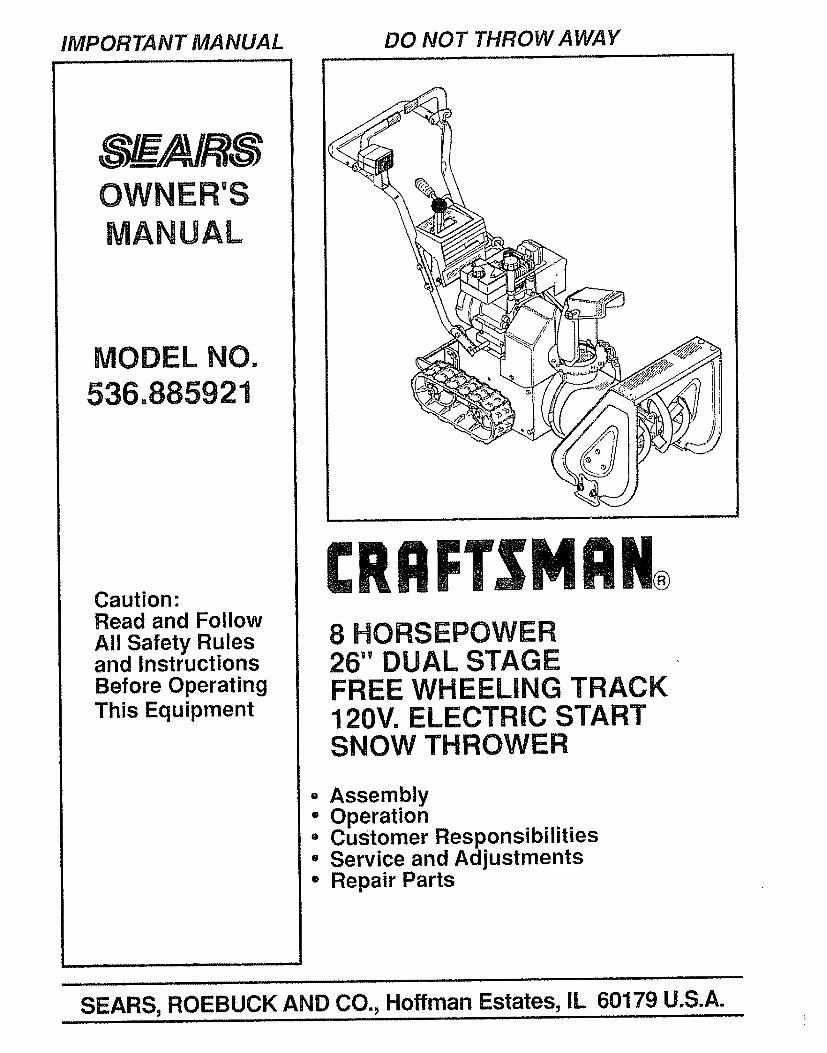
SAFETY RULESCAUTION: ALWAYS DISCONNECT SPARK PLUG WIRE AND ._PLACE WIRE WHERE IT CANNOT CONTACT SPARK PLUG ATO PREVENT ACCIDENTAL STARTING WHEN SETTING-UP,TRANSPORTING, ADJUSTING OR MAKING REPAIRS,
IMPORTANTSAFETY STANDARDS REQUIRE OPERATOR PRESENCE CONTROLS TO MINIMIZE THERISK OF INJURY, YOUR SNOW THROWER IS EQUIPPED WITH SUCH CONTROLS. DO NOTATTEMPT TO DEFEAT THE FUNCTION OF THE OPERATOR PRESENCE CONTROL UNDERANY CIRCUMSTANCES
TRAINING
1o Read the operator's manual carefully. Bethoroughly familiar with the controls and theproper use of the snow thrower. Know how tostop the snow thrower and disengage thecontrols quickly.
2. Never allow children to operate the snowthrowerand keep them away while it is operating. Neverallow adults to operate the snow thrower withoutproper instruction° Do not carry passengers.
3. Keep the area of operation clear of all persons,particularly small children, and pets.
4. Exercise caution to avoid slipping or falling,especially when operating in reverse.
PREPARATION
1. Thoroughly inspect the area where the snowthrower is to be used and remove all doormats,sleds, boards, wires, and other foreign objects.
2. Disengage all clutches and shift into neutralbefore starting the engine (motor).
3o Do not operatethe snowthrowerwithout wearingadequate winter outer' garments. Wear footwearthat will improve footing on slippery surfaces.
4_ Handle fuel with care; it is highly flammable_
(a) Use an approved fuel container.
(b) Never remove fuel tank cap or add fuel to arunning engine or hot engine.
(c) Fill fuel tank outdoors with extreme care.Never fill fuel tank indoors.
=
(d) Replace fuel tank cap securely and wipe upspilled fuel.
(e) Never store fuel or snow thrower with fuel inthe tank inside of a building where fumes mayreach an open flame or spark,
(f) Check fuel supply before each use, allowingspace for expansion as the heat of the engine(motor) and/or sun can cause fuel to expand.
Use extension cords and receptacles as specifiedby the manufacturer for all snow throwers withelectric drive motors or electric starting motors.
6, Adjust the snow thrower height to clear gravel orcrushed rock surfaces.
7. Never attempt to make any adjustments while theengine (motor) is running (except whenspecifically recommended by the manufacturer).
8. Let engine (motor) and snow thrower adjust tooutdoor temperatures before starting to clearsnow,
9. Always wear safety glasses or eye shields duringoperation or while performing an adjustment orrepair to protect eyes from foreign objects thatmay be thrown from the snow thrower.
OPERATION
1. Do not put hands or feet near or under rotatingparts. Keep clear of the discharge opening at alltimes°
2, Exercise extreme caution when operating on orcrossing gravel drives, walks, or roads. Stay alertfor hidden hazards or traffic.
3_
4_
After striking a foreign object, stop the engine(motor), remove the wire from the spark plug,disconnect the cord on electric motors,thoroughly inspect the snow thrower for anydamage, and repair the damage before restartingand operating the snow thrower_
if the snow thrower should start to vibrateabnormally, stop the (motor) and checkimmediately for the cause. Vibration is generallya warning of trouble.
5. Stop the engine (motor) whenever you leave theoperating position, before unclogging the auger!impeller housing or discharge guide, and whenmaking any repairs, adjustments, or inspections.
6. When cleaning, repairing, or inspecting, makecertain the auger/impeller and all moving partshave stopped° Disconnect the spark plug wireand keep the wire away from the plug to preventaccidental starting.
, Take all possible precautions when leaving thesnow thrower unattended. Disengage the auger/impeller, shift to neutral, stop engine, andremove key.
2
SAFETY RULES
. Do not run the engine indoors, except when startingthe engine and for transporting the snow thrower inor out of the building. Open the outside doors;exhaust fumes are dangerous (containing CARBONMONOXIDE, an ODORLESS and DEADLY GAS).
9. Do not clear snow across the face of slopes.Exercise caution when changing direction onslopes. Do not attempt to clear steep slopes
10, Never operate the snow thrower without properguards, plates or other safety protective devicesin place.
11. Never operate the snow thrower near glassenclosures, automobiles, window wells,drop-offs, and the like without proper adjustmentof the snow discharge angle. Keep children andpets away.
12. Do not overload the machine capacity byattempting to clear snow at too fast a rate°
13. Neveroperatethe snowthrowerat high transportspeeds on slippery surfaces° Look behind anduse care when backing.
14. Never direct discharge at bystanders or allowanyone in front of the snow thrower.
15. Disengage power to the auger/impeller whensnow thrower is transported or not in use..
167 Use only attachments and accessories approvedby the manufacturer of the snow thrower (suchas tire chains, electric start kits, etc.)
17. Never operate the snow thrower without goodvisibility or light. Always be sure of your footing,and keep a firm hold on the handles. Walk; neverrun.
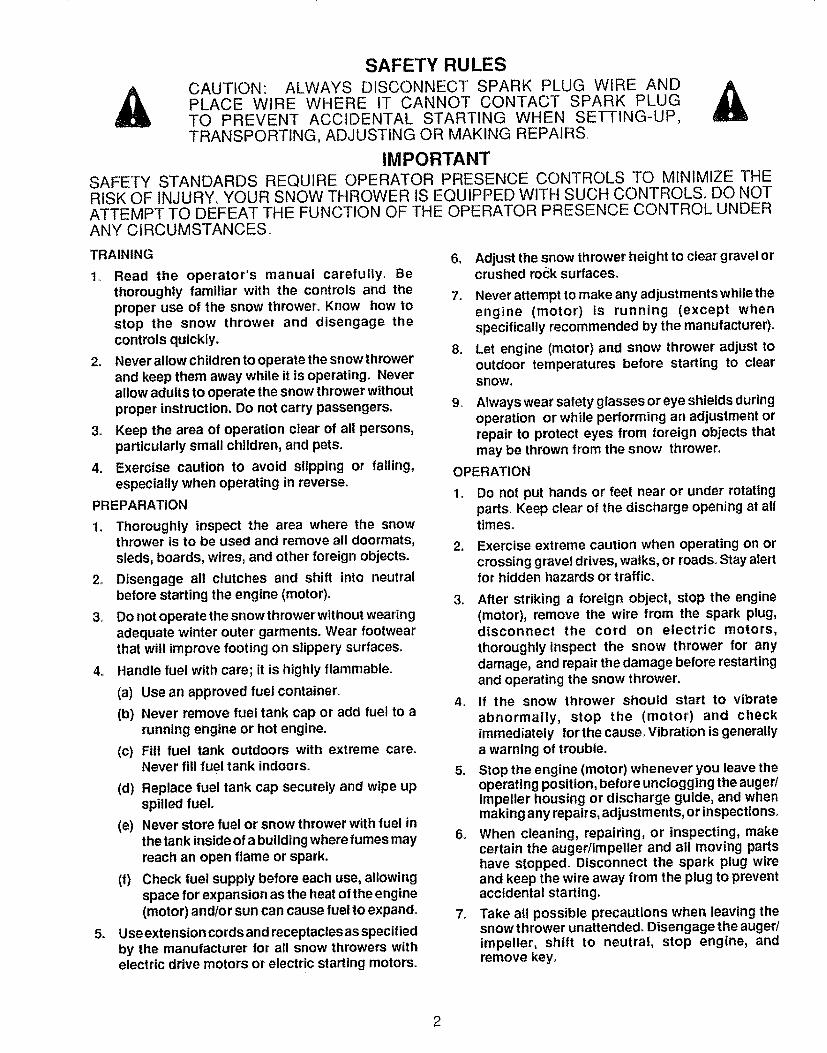
CAUTION: AVOID IN-JURY FROM ROTAT-ING AUGER° KEEPHANDS, FEET, AND
AWAY! j
ENGINE BEFOREUNCLOGGING
DISCHARGE CHUTE!
MAINTENANCE AND STORAGE
1. Check shear bolts and other bolts frequently forimproper tightness to be sure the snow throweris in safe working condition.
2. Never store the snow thrower with fuel in the fueltank inside a building where ignition sources arepresent such as hot water and space heaters,clothes dryers, and the like. Allow the engine tocool before storing in any enclosure.
3. Always refer to operator's manual instructionsfor important details if the snow thrower is to bestored for an extended period.
4. Maintain or replace safety and instruction labels,as necessary.
5. Run the snow thrower a few minutes afterthrowing snow to prevent freeze-up of the auger/impeller.
WARNING
This snow thrower is for use on sidewalks,driveways, and other ground level surfaces.
CAUTION should be exercised while using onsteep sloping surfaces. DO NOT USE SNOWTHROWER ON SURFACES ABOVE GROUNDLEVEL such as roofs of residences, garages,porches or other such structures or buildings,
LOOK FOR THIS SYMBOL TO POINT OUT
_ IMPORTANT SAFETY PRECAUTIONS. ITMEANS--ATTENTION.It! BECOME ALERT!{{YOUR SAFETY IS INVOLVED.
3
CONGRATULATIONS on your purchase of a SearsCraftsman Snow Thrower.. It has been designed, engi-neered and manufactured to give you the best possibledependability and performance..Should you experience any problem you cannot easilyremedy, please contact your nearest Sears ServiceCenter!Department, Sears has competent, well-trainedtechnicians and the proper tools to service or repair thisunitPlease read and retain this manual. The instructions will
enable you to assemble and maintain your snow throwerproperly. Always observe the "SAFETY RULES.."
MODELNUMBER 536.885921
SERIALNUMBERDATE OFPURCHASE
THE MODEL AND SERIAL NUMBERS WILL BEFOUND ON A DECAL ATTACHED TO THE REAROF THE SNOW THROWER HOUSING
YOU SHOULD RECORD BOTH SERIAL NUMBERAND DATE OF PURCHASE AND KEEP 1NA SAFEPLACE FOR FUTURE REFERENCE
, i,i
MAINTENANCE AG REEMENTA Sears Maintenance Agreement is available on thisproduct Contact your nearest Sears Store for details
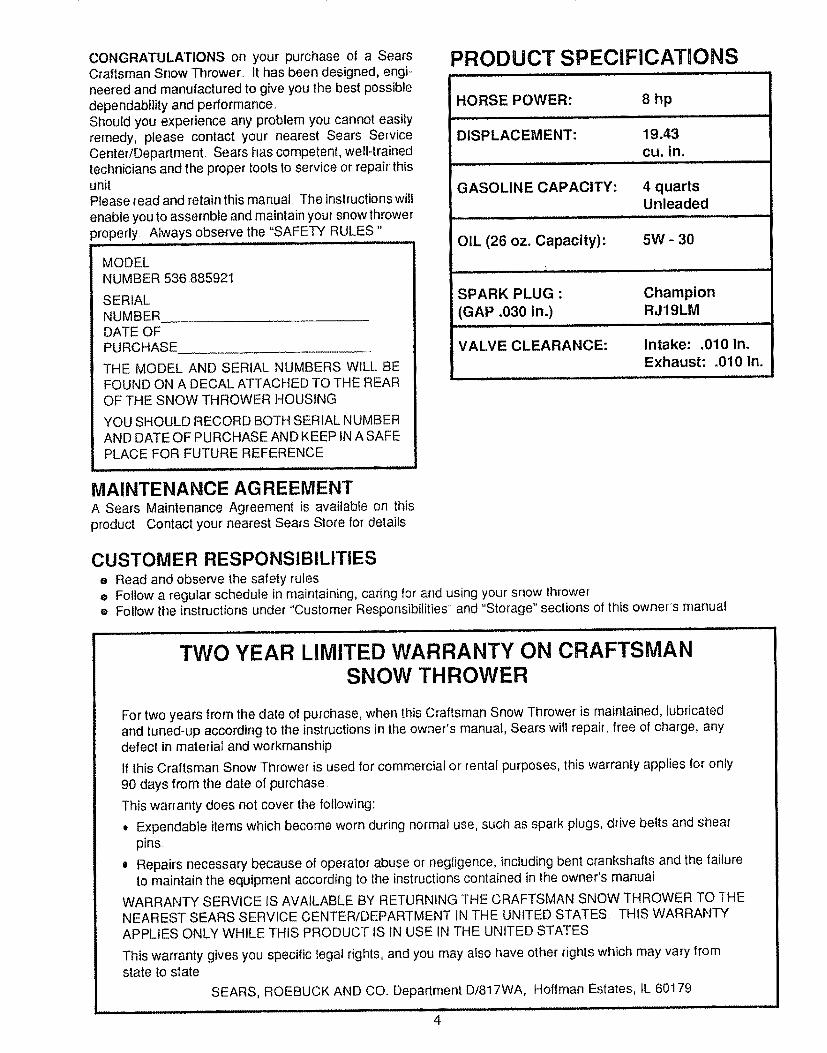
PRODUCT SPECIFICATIONS
HORSE POWER: 8 hp
DISPLACEMENT: 19.43cu. in,
GASOLINE CAPACITY: 4 quartsUnleaded
OIL (26 oz, Capacity): 5W - 30
SPARK PLUG : Champion
(GAP .030 in.) RJ19LM
VALVE CLEARANCE: intake: .010 in,Exhaust: .010 in.
CUSTOMER RESPONSIBILITIESe Read and observe the safety rulese Follow a regular schedule in maintaining, caring for and using your snow thrower® Follow the instructions under "Customer Responsibilities and "Storage" sections of this owners manual
TWO YEAR LIMITED WARRANTY ON CRAFTSMANSNOW THROWER
For two years from the date of purchase, when this Craftsman Snow Thrower is maintained, lubricatedand tuned-up according to the instructions in the owner's manual, Sears witl repair, free of charge, anydefect in material and workmanship
If this Craftsman Snow Thrower is used for commercial or rental purposes, this warranty applies for only
90 days from the date of purchase.
This warranty does not cover the following:
o Expendable items which become worn during normal use, such as spark plugs, drive belts and shearpins..
o Repairs necessary because of operator abuse or negligence, including bent crankshafts and the tailureto maintain the equipment according to lhe instructions contained in the owner's manual
WARRANTY SERVICE IS AVAILABLE BY RETURNING THE CRAFTSMAN SNOW THROWER TO THENEAREST SEARS SERVICE CENTERfDEPARTMENT IN THE UNITED STATES THIS WARRANTYAPPLIES ONLY WHILE THIS PRODUCT tS IN USE IN THE UNITED STATES.
This warranty gives you specific legal rights, and you may also have other rights which may vary fromstate to state.
SEARS, ROEBUCK AND CO.. Deparlrnent Dt817WA, Hoffman Estates, IL 60179
4
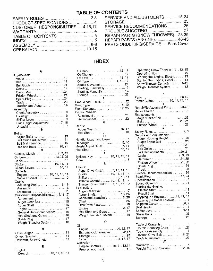
TABLE OF CONTENTSSAFETY RULES .......................................................2,3PRODUCT SPECIFICATIONS ..............................4CUSTOMER RESPONSIBILITIES ..... 4,I6,17WARRANTY .........................................................................4TABLE OF CONTENTS ...........................................5INDEX ...........................................................................5ASSEMBLY .............................................................6-9OPERATION ....................................................10-t5
SERVICE AND ADJUSTMENTS ...............18-24STO RAGE ...................................................................25SERVICE RECOMMENDATIONS ................ 26TROUBLE SHOOTING .........................................27
REPAIR PARTS (SNOW THROWER) .....28-39REPAIR PARTS (ENGINE) .........................40-43PARTS ORDERING/SERVICE .......Back Cover
A
Adjustment:Auger ........................................................19Belt ............................................................19Belt Guide ....................................................21Cable .........................................................19Carburetor .................................................24Friction Wheel ........................................21
Spark Plug .................................... 24Track .............................................. 23Traction and Auger ......................... 19
Assembly:Crank Assembty ................................. 8Headlight ............................................. 9Shifter Lever ...............................................9Skid Height Adjustment ,7, 18Unpacking .............................. 7
BBelts:
Adjust Belts ........................................ 19Belt Guide Adjustment .............. 21Belt Maintenance ............................. 16
Replace Belts ............................ 20, 21C
Cables, Clutch ............... 7, 9, !9Carburetor: ...................... t 3,24, 25Chain ................................................................!6Choke ........................................t O, 11, 13Clutch, Levers ..................... I0, 1IControls:
Engine .................................!0, 11, I3, 14Snow Thrower ......................................I0
Crank:Adjusting Rod .....................................8, 18Assembly ........................................ 8Operation ................................................11
Customer Responsibilities ...........4,16,17Agreement ............................................4Auger Gear Box ............................... t6Auger Shaft ................................ t 6Engine ................................................ 17General Recommendations ........... 16Hex Shaft and Gears ................... 16
Spark Plug ............................ 17Weight Transfer System ............ 16
DDrive, Auger ...........................................11Drive, Traction ................................... 11Deflector, Snow Chute .......... 11
E
Engine:Control ............................1O, 1I, 13, 14
INDEX
Oil Cap .............................. I2, 17Oil Change ................ 17Oil Level ................... 12, 17Oil Type .....................................4, 12, 17Speed Governor ............................... 24Starting, Electrically ...............................13Starting, Manually ...............................14Storage ........................................ 25
FFree-Wheel, Track ......................... I2Fuel, Type .................................. 4, t2Fuel, Storage ...................... !2, 25Friction Wheel:
Adjustment ............................................2tReplacement .................................... 22
GGears:
Auger Gear Box ..... t 6, 17Hex Shaft ........................ 16
HHandle, Upper and Lower ........................7Headlight ......................... 9, 10Height Adjust Skids ........... 7, 18Hex Shaft ..... 16, 17iIgnition, Key ............ 10, 11, 13, 14Index ............................ 5
LLevers:
Auger Drive Clutch ........7, I0, 11, 19Choke ......................... 10, II, t3, t4Shifter .................................... 9, I0, l IThrottle Control ....................i0, ti, t3, 14Traction Drive Clutch ..... 7, 10, 11, 19
Lubrication:Auger Gear Box ...................................17Auger Shaft ......................... 16, 26Chain and Sprockets ............. 16, 26Chart ............................................... 26Disc Drive Plate ....................................16Engine ...............................................12, 17Hex Shaft and Gears ........................17
Weight Transfer System .......... 16
OOil:
Engine ......................................4, 12, 17Extreme Cold Weather .................12,17Storage ..................................... 25Type ........................ 4, 12, 17
Operation:Engine Controls ........... 10, I1, 13,t4Free-Wheel, Track ............ 12
Operating Snow Thrower. tt, 12, t5Operating Tips ............................... 15Starting the Engine, Electric ...........13Starting the Engine, Recoil ............ 14Snow Thrower Controls ............. !0-12Weight Transfer System ............ 12
PParts ........................................ 28-40Primer Button ............. 10, 1I, t3, 14
R
Repair/Replacement Parts ........ 28-40Recoil Starter ...................................... 14
Replacements:Auger Shear Bolt ................... 23Belts .............................. 20, 2tFriction Wheel ...................... 22
S
Safety Rules .................................... 2, 3Service and Adjustments:
Auger Housing Height .......... 7, t8Auger Shear Bolt ......................... 23Belts ...................................... 19-21Belt Guide ...................................... 2tBelt Replacements .......... 20, 2tCable ...................... 7, 9, 19Carburetor ............................. 24, 25Friction Wheel ............... 21,22Spark Plug ............................. 24Track ......................................... 23
Service Recommendations ...... 26
Spark Plug .......................... 17, 24Specifications .............................. 4Speed Governor .......................... 24Starting the Engine:
Electric Start ............................. 13Recoil Start ........................................ 14
Stopping the Engine .................11, t3, 14Stopping the Snow Thrower ........... 11Shipping Carton .......................... 6. 7Skid Height ......................... 7, I8Shifter Lever .................... g-t 1Shear Bolts ............................. 23
Storage ....................... 25T
Table of Contents ...................... 5Troubfe Shooting Chart ................. 27Tools for Assembly ............................. 6Traction Drive Belt ....................... !9, 21Track Adjustment .............................. 23
WWarranty .................................. 4Weight Transfer System ......... 12. t8
5
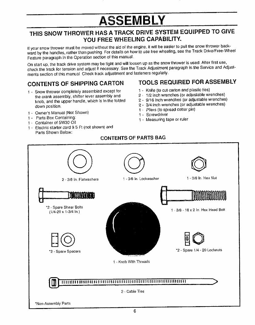
ASSEMBLYTHIS SNOW THROWER HAS A TRACK DRIVE SYSTEM EQUIPPED TO GIVE
YOU FREE WHEELING CAPABILITY.
if your snow thrower must be moved without the aid of the engine, it will be easier to pull the snow thrower back-ward by the handles, rather than pushing For details on how to use free wheeling, see the Track Drive/Free-WheelFeature paragraph in the Operation section of this manual.
On start up, the track drive system may be tight and will loosen up as the snow thrower' is used. After first use,check the track for tension and adjust if necessary. See the Track Adjustment paragraph in the Service and Adjust-ments section of this manual Check track adjustment and fasteners regularly.
CONTENTS OF SHIPPING CARTON TOOLS REQUIRED FOR ASSEMBLY
! - Snow thrower completely assembled except for 1 -the crank assembly, shifter lever assembly and 2 -knob, and the upper handle, which is in the folded 2 -down position. 2
1 - Owner's Manual (Not Shown) t -1 - Parts Box Containing: 1 -t - Container of 5W30 Oil 1 -
1 - Electric starter cord 9.5 Ft (not shown) andParts Shown Below:
CONTENTS OF PARTS BAG
Knife (to cut carton and plastic ties)1/2 inch wrenches (or' adjustable wrenches)9/t 6 inch wrenches (or adjustable wrenches)3/4 inch wrenches (or adjustable wrenches)Pliers (to spread cotter pin)Screwdriver
Measuring tape or ruler
2 - 3/8 In..Flatwashers 1 - 3/8 in Lockwasher
©1 - 3/8 In. Hex Nut
"2 - Spare Shear Bolts(1/4-20 x t-3/4 In.)
*2 - Spare Spacers
! - 3t8 - 16 x 2 In, Hex Head Bolt
*2 - Spare 1/4 - 20 Locknuts
1 - Knob With Threads
_iiiiillilllliilllliilliilliliiiililiiiiiiiiillllilltllilllilllil'lll ..........._
2 - Cabte Ties
"Non-Assemb{y Partsi t i i iiu lll_ li,Hi, i i i lll i,i/i i, i,u,i.i H,i ,,it ,i i_tlll,l.,
6
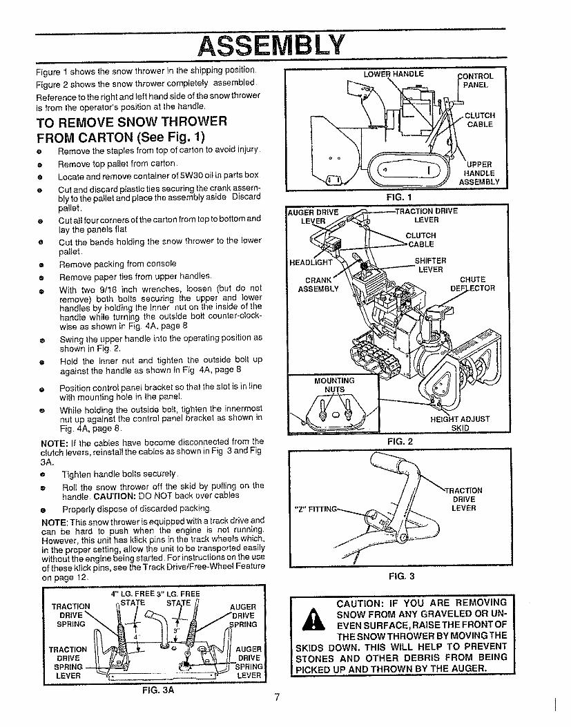
........................................................................ASSE....LY .......................LowEnHANI LE..........Figure 1 shows the snow thrower in the shipping position,
Figure 2 shows the snow thrower completely assembled,
Reference to the right and left hand side of the snow throweris from the operator's position at the handle,
TO REMOVE SNOW THROWER
FROM CARTON (See Fig. 1)e Remove the staples from top of carton to avoid injury
e Remove top pallet from carton.
• Locate and remove container of 5W30 oil in parts box,
e Cut and discard plastic ties securing the crank assem.bly to the pallet and place the assembly aside. Discardpallet,
e Cut all fourcorners of the carton from top to bottom andlay the panels flat,
• Cut the bands holding the snow thrower to the towerpallet..
e Remove packing from console
• Remove paper ties from upper handles,
e With two 9/!6 inch wrenches, _oosen (but do notremove) both bolts securing the upper and lowerhandles by holding the inner nut on the inside of thehandle wh}le turning the outside bolt counter-clock-wise as shown in Fig 4A, page 8
e Swing the upper handle into the operating position asshown in Fig, 2,
e Hold the inner nut and tighten the outside bolt upagainst the handle as shown in Fig 4A, page 8
PANEL
CLUTCHCABLE
AUGERD,iV .........
UPPERHANDLE
ASSEMBLY
FIG. 1
DRIVELEVER
CLUTCH
HEADLIGHT SHIFTERLEVER
CHUTE
e Position control panel bracket so that the slot is in tinewith mounting hole in the panet.
e While holding the outside bo_t, tighten the innermostnut up against the control panel bracket as shown inFig. 4A, page 8,
NOTE: If the cables have become disconnected from theclutch levers, reinstall the cables as shown in Fig 3 and Fig3A,,o
O
Tighten handle bolts securely
Rol! the snow thrower off the skid by pulling on thehandle, CAUTION; DO NOT back over cables
e Properly dispose of discarded packing.
NOTE: This snow thrower is equipped with a track drive andcan be hard to push when the engine is not running,However, this unit has kfick pins in the track wheels which,in the proper setting, allow the unit to be transported easilywithout the engine being started, For instructions on the useof these klick pins. see the Track Drive/Free-Wheel Featureon page I2,
4" LG, FREE 3" LG, FREE
TRACTION _STATEDRIVE"-... /SPR,.G
TRAOT,O.DRWE II ///,_71_,
SPRING ---_LEVEF_ _ .
FIG. 3A
FIG. 2, N
DRIVELEVER
FIG, 3
CAUTION: IF YOU ARE REMOVING
A SNOW FROM ANY GRAVELED OR UN-EVEN SURFACE, RAISE THE FRONT OFTHE SNOWTHROWER BY MOVING THE
SKIDS DOWN. THIS WiLL HELP TO PREVENT
STONES AND OTHER DEBRIS FROM BEING
PICKED UP AND THROWN BY THE AUGER.
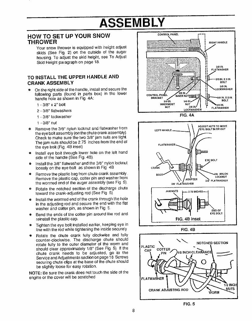
HOW TO SET UP YOUR SNOWTHROWER
Your snow thrower is equipped with height adjustskids (See Fig. 2) on the outside of the augerhousing. To adjust the skid height, see To AdjustSkid Height paragraph on page 18,.
TO INSTALL THE UPPER HANDLE ANDCRANK ASSEMBLY
On the right side of the handle, installand secure thefollowing parts (found in parts box) in the lowerhandle hole as shown in Fig 4A:
1 - 3/8" x 2" bolt
2 - 3/8" flatwashers
t - 3/8" lockwasher
t - 3/8" nut
® Remove the 318" nylon locknut and flatwasher fromthe eye bolt assembly (on the chute crank assembly).Check to make sure the two 3/8" jam nuts are tight,The jam nuts should be 275 inches from the end ofthe eye bolt (Fig. 4B inset)
e Install eye bolt through lower hole on the left handside of the handle (See Fig. 4B).
• Install the 3/8" flatwasher and the 3/8" nylon locknutloosely on the eye bolt as shown in Fig 4B
e Remove the plastic bag from chute crank assemblyRemove the plastic cap, cotter pin and washer fromthe wormed end of the auger assembly (see Fig 5),
® Rotate the notched section of the discharge chutetoward the crank-adjusting rod (See Fig 5).
e install the wormed end of the crank fhrough the holein the adjusting rod and secure the end with the flatwasher and cotter pin, as shown in Fig 5
• Bend the ends of the cotter pin around the rod andreinstall the plastic cap,,
e Tighten the eye bolt installed earlier, keeping eye inline with the rod while tightening the inside securely
• Rotate the chute crank fully clockwise and fullycounter-clockwise. The discharge chute shouldrotate fully to the outer diameter of the worm andshould clear approximately 1/8" (See Fig. 5).. If thechute crank needs to be adjusted, go to theService and Adjustments section on page 18 Screwssecuring chute clips at the base of the chute shouldbe slightly loose for easy rotation,.
NOTE: Be sure the crank does not touch the side of theengine or the cover will be scratched,
BRACKET
3mlN, BOLT
INNERMOST NUT
NUT 3,"8 FLAT'WASHERLOCKWASHER
FIG. 4A
ADJUST NUTS TO MOVEEYE :BOLT IN OR OUT
CRANK
EYE BOLT
NYLON
3_/8 LOCKNUTFLATWASHER3/8 _ FLA"P#ASHER
JAM NUTS
2. 75 IN_
I END OFEYE BOLT
FIG. 4B inset
i[ iL ,,,,,,,,,,,
FIG. 4B
"_" NOTCHED SECTIONPLASTIC % ,.
CAP COTTER
PIN /8 INCHCLEABANC
O
FLA
| _ _k\,, J//_".,,_ 1/2 INCH
8
FIG, 5
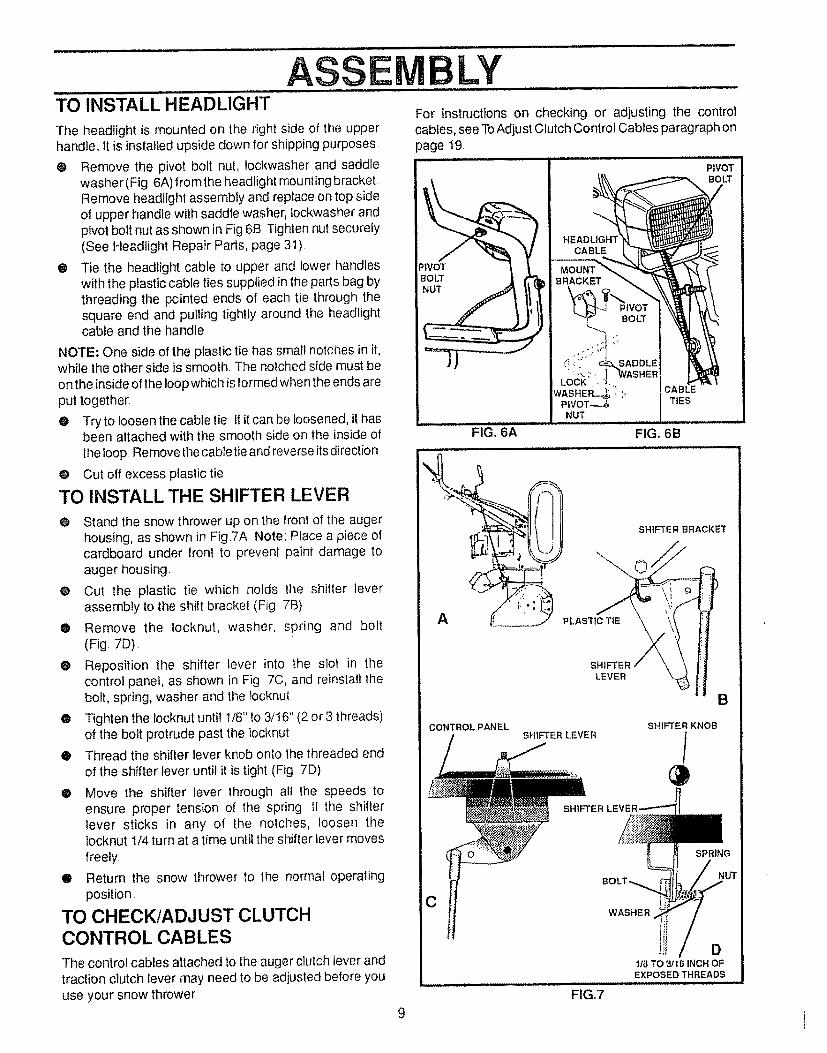
ASSEM LYTO INSTALL HEADLIGHT
The headlight is mounted on the right side of the upperhandle., it is installed upside down for shipping purposes
® Remove the pivot bolt nut, lockwasher and saddlewasher (Fig. 6A) from the headlight mounting bracketRemove headlight assembly and replace on top sideof upper handle with saddJe washer, Jockwasher andpivot bolt nut as shown in Fig 6B Tighten nut securely(See Headlight Repair Parts, page 31).
® Tie the headlight cable to upper and lower handleswith the plastic cable ties supplied in the parts bag bythreading the pointed ends of each tie through thesquare end and putling tightly around the headlightcable and the handle
NOTE: One side of the plastic tie has small notches in it,while the other side is smooth. The notched side must beon the inside o! the loop which is formed when the ends areput together:
@ Try to loosen the cable tie If it can be loosened, it hasbeen attached with the smooth side on the inside ofthe loop. Removethe cable tie and reverse its direction
@ Cut off excess plastic tie
TO INSTALL THE SHIFTER LEVER
O Stand the snow thrower up on the lronl of the augerhousing, as shown in Fig.7A Note: Place a piece ofcardboard under front to prevent paint damage toauger housing.
• Cut the plastic tie which holds the shifter leverassembly to the shift bracket (Fig 7B)
• Remove the iocknut, washer, spring and bolt(Fig 7D)..
@ Reposition the shifter lever into the slot in thecontrol panel, as shown in Fig 7C, and reinstall thebolt, spring, washer and the Iocknut
• Tighten the locknut until 1/8" to 3/t6" (2 or3 threads)of the bolt protrude past the locknut
® Thread the shifter lever knob onto the threaded end
of the shifter lever until it is tight (Fig 7D)
• Move the shifter lever through all the speeds toensure proper tension of the spring If the shifterlever sticks in any ol the notches, loosen thelocknut 1/4 turn at a time until the shifter lever movesfreely
• Return the snow thrower to the normal operatingposition.
TO CHECK/ADJUST CLUTCHCONTROL CABLES
The control cables attached to the auger clutch lever andtraction clutch fever may need to be adjusted before youuse your snow thrower
For instructions on checking or adjusting the controlcables, see To Adjust Clutch Control Cables paragraph onpage 19.
PIVOT
_'IVOTBOLTNUT
BOLT
TIES
FIG_ 6A FIG. 6B
SHIFTER
LEVER
CONTROLPANELSHIFTER LEVER
SHIFTER
SHIFTER KNOB
/
SPRING
9
CWASHER
Dlib TO _t6 INCH OFEXPOSEDTHREADS
FtG.7
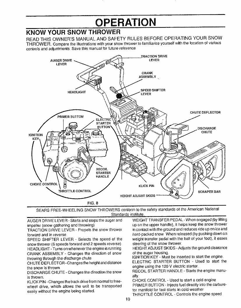
OPERATIONKNOW YOUR SNOW THROWERREAD THIS OWNER'S MANUAL AND SAFETY RULES BEFORE OPERATING YOUR SNOWTHROWER° Compare the illustrations with your snow thrower to familiarize yourself with the location of variouscontrols and adjustments, Save this manual for' future reference,,
AUGER DRIVELEVER
,TRACTION DRIVELEVER
CRANKASSEMBLY
m
HEADLIGHTSPEED SHIFTER
TARTER
IGNITIONKEY
CHUTE DEFLECTOR
DISCHARGECHUTE
RECOILSTARTERHANDLE
CHOKECONTROL
THROTTLE CONTROL
KLICK PIN
HEIGHT ADJUST SKIDS
SCRAPER BAR
FIG. 8
SEARS FREE-WHEELING SNOW THROWERS conform to the safety standards of the American NationalStandards Institute.
AUGER DRIVE LEVER - Starts and stops the auger and
impeller (snow gathering and throwing)TRACTION DRIVE LEVER - Propels the snow throwerforward and in reverse,SPEED SHIFTER LEVER - Selects the speed of thesnow thrower (6 speeds forward and 2 speeds reverse)HEADLIGHT - Turns on whenever the engine is runningCRANK ASSEMBLY - Changes the direction of snowthrowing through the discharge chute,CHUTE DEFLECTOR - Changes the height and distancethe snow is thrown.DISCHARGE CHUTE - Changes the direction the snowis thrown.KLICK PIN - Changes the track drive from normal to free-wheel drive, which allows the unit to be transportedeasily without the engine being started.
WEIGHT TRANSFER PEDAL- When engaged (by liftingup on the upper handle), it hefps keep the snow throwerin contact with the ground and reduces ride up on ice andhard-packed snow When released (by pushing down onweight transfer pedal with the ball of your foot), it easessteering of the snow thrower.HEIGHT ADJUST SKIDS - Adjusts the ground clearanceof the auger housingIGNITION KEY - Must be inserted to start the engineELECTRIC STARTER BUTTON - Used to start the
engine using the 120 V electric starter,.RECOIL STARTER HANDLE _Starts the engine manu_.ally.CHOKE CONTROL - Used to start a cold enginePRIMER BUTTON - Injects fuel directly into the carbure-tor manifold for fast starts in cold weatherTHROTTLE CONTROL - ControLs the engine speed
10
The operation of any snow thrower can result in foreign objects being thrown into theeyes, which can result in severe eye damage Always wear safety glasses or eyeshields while operating the snow thrower.We recommend standard safety glasses or wide vision safety mask for over your
glasses avaRable at SEARS Retail or Catalog Stores..iii.i....... i i i i i,,i :: iJ .......... ................ :
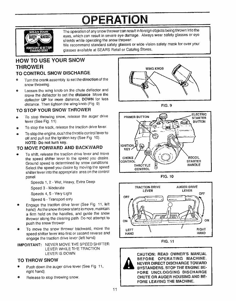
HOW TO USE YOUR SNOWTHROWERTO CONTROL SNOW DISCHARGE
o Turn the crank assembly to set the direction of thesnow throwing.
e Loosen the wing knob on the chute deflector andmove the deflector to set the distance Move thedeflector UP for more distance, DOWN for lessdistance Then tighten the wing knob (Fig 9)
TO STOP YOUR SNOW THROWER
WING KNOB
FIGo9
e To stop throwing snow, release the auger drivelever (See Fig. 11)
• To stop the track, release the traction drive lever.
= To stop the engine, pushthe throttlecontrol lever tooff and pull out the ignition key (See Fig 10).NOTE: Do not turn key.
TO MOVE FORWARD AND BACKWARD
iMPORTANT:
To shift, release the traction drive tever and movethe speed shifter lever to the speed you desire.Ground speed is determined by snow conditionsSelect the speed you desire by moving the speedshifter lever into the appropriate area on the controlpanel.
Speeds 1,2 - Wet, Heavy, Extra Deep
Speed 3 - Moderate
Speeds 4, 5 - Very Light
Speed 6 - Transport only
Engage the traction drive lever (See Fig 1I, lefthand) Asthe snowthrowerstarts to move, maintaina firm hold on the handles, and guide the snowthrower along the clearing path Do not attempt topush the snow thrower
To move the snow thrower backward, move thespeed shifter lever into first or second reverse andengage the traction drive lever (left hand)
NEVER MOVE THE SPEED SHIFTERLEVER WHILE THE TRACTIONLEVER fS DOWN
TO THROW SNOW
o
o
Push down the auger drive lever (See Fig 1t,right hand)..
Release to stop throwing snow..
CHOKECONTROL
THROTTLECONTROL
FIG. 10
Hi i =
TRACTION DRIVELEVER
HAND
A
STARTERHANDLE
ii i,, .................
AUGER DRIVELEVER
OFF
RIGHTHAND
FIG. 11
CAUTION: READ OWNER'S MANUALBEFORE OPERATING MACHINE.NEVER DIRECT DISCHARGE TOWARDBYSTANDERS. STOP THE ENGINE BE-FORE UNCLOGGING DISCHARGECHUTE OR AUGER HOUSING AND BE-FORE LEAVING THE MACHINE_
1t
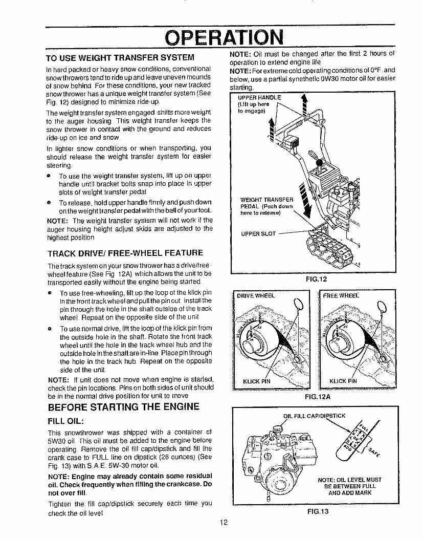
OPERAI=IONTO USE WEIGHT TRANSFER SYSTEM
In hard packed or heavy snow conditions, conventionalsnow throwers tend to ride up and leave uneven moundsof snow behind. For these conditions, your new trackedsnow thrower has a unique weight transfer system (SeeFig,, 12) designed to minimize dde-up,.
The weight transfer system engaged shifts more weightto the auger housing. This weight transfer keeps thesnow thrower in contact with the ground and reducesride-up on ice and snow..
In lighter' snow conditions or when transporting, youshould release the weight transfer system for easiersteering.
® To use the weight transfer system, lift up on upperhandle until bracket bolts snap into place in upperslots of weight transfer pedal.
e To release, hold upper handle firmly and push downon the weight transfer pedal with the ball of your fool
NOTE: The weight transfer system will not work if theauger housing height adjust skids are adjusted to thehighest position
TRACK DRIVE/FREE-WHEEL FEATURE
The track system on your snow thrower has adrive/free_wheel feature (See Fig, 12A) which allows the unit to betransported easily without the engine being started..
® To use free-wheeling, lift up the loop of the kfick pinin the front track wheel and pull the pin out Install thepin through the hole in the shaft outside of the trackwheel Repeat on the opposite side of the unit
o To use normal drive, lift the loop of the klick pin fromthe outside hole in the shaft.. Rotate the front trackwheel until the hole in the track wheel hub and theoutside hole in the shaft are in-line Place pin throughthe hole in the track hub. Repeat on the oppositeside of the unit,.
NOTE: If unit does not move when engine is started,check the pin locations, Pins on both sides of unit shouldbe in the normal drive position for unit to move,
BEFORE STARTING THE ENGINE
FILL OIL:
This snowthrower was shipped with a container of5W30 oi!. This oil must be added to the engine beforeoperating Remove the oil fii! cap/dipstick and fill thecrank case to FULL line on dipstick (26 ounces) (SeeFig, 13) with SAE 5W-30 motor oil
NOTE: Engine may already contain some residualoil. Check frequently when filling the crankcase. Donot over fill.
Tighten the fill cap/dipstick securely each time youcheck the oil level,
NOTE: Oil must be changed after the first 2 hours ofoperation to extend engine lifeNOTE: For extreme cold operating conditions of 0°F andbelow, use a partial synethetic 0W30 motor oil for' easierstarting. ........................
UPPER HANDLE
(Lift up hereto engage)
WEIGHT TRANSFER
PEDAL (Push downhere to release)
UPPER SLOT
DRIVE WHEEL
FIG. 12
FREEWREEt_
KUCK PIN
FIG.12A
OIL FILL CAPtDIPSTICK
%
NOTE: OIL LEVEL MUSTBE BETWEEN FULL
AND ADD MARK
12
FIGo13
OPE ATIOFILL GAS:
Fill the fuel tank with clean, fresh, unleaded gradeautomotive gasoline. Be sure that the container youpour the gasoline from is clean and free from rust orother foreign particles. Never use gasoline that may bestale from long periods of storage in the container.
NOTE: SAE. 5W-30 motor oil may be used to makestarting easier in areas where temperature is consis-tentty 20° F or lower.
WARNING: Experience indicates that alcohol blendedfuels (called gasohol or those using ethanol or metha-nol) can attract moisture which leads to separation andformation of acids during storage Acidic gas can dam-age the fuel system of an engine while in storage
To avoid engine problems, the fuel system should beemptied before storage for 30 days or longer Start theengine and let it run untilt he fuel lines and carbureto rareempty. Use the carburetor bowl drain to empty residualgasoline from the float chamber (Fig. 41, page 25) Usefresh fuel next season. (See Storage instruclions onpage 25 for additional information)
Never use engine or carburetor cleaner products in thefuel tank or permanent damage may occur.
_ AUTION: GASOLINE IS FLAMMABLEAND CAUTION MUST BE USED WHENHANDLING OR STORING IT,,
DO NOT FILL FUEL TANK WHILE SNOW
THROWER IS RUNNING, WHEN 1T IS HOT, ORWHEN SNOW THROWER IS IN AN ENCLOSEDAREA.
KEEP AWAY FROM OPEN FLAME OR AN ELEC-TRICAl. SPARK AND DO NOT SMOKE WHILEFILLING THE FUEL TANK,.
NEVER FILL THE TANK COMPLETELY. FILLTHE TANKTOWlTHIN 1/4".- t12" FROMTHETOPTO PROVIDE SPACE FO R EXPANSION OF FUEL.
ALWAYS FILL FUEL TANK OUTDOORS ANDUSE A FUNNEL OR SPOUT TO PREVENT SPILL-INGo
MAKE SURE TO WIPE UP ANY SPILLED FUELBEFORE STARTING THE ENGINE.
STORE GASOLINE IN A CLEAN, APPROVEDCONTAINER AND KEEP THE CAP IN PLACE ONTHE CONTAINER.
TO........STOP ENGINE .......................................
• To stop engine, move the throttle control lever toSTOP position and remove key Keep the key in asafe place. The engine will not start without the key
CARBURETORThe factory settings for the carburetor are for mostconditions. If the engine is operated under the following
conditions, you can adjust carburetor mixture See "HowTo Adjust The Carburetor"(See Service and Adjustments,page 24)_,
® The engine has a loss o{ power or does not runsmooth.
® The engine's operated above 4,000 feet
TO START ENGINE (Electric Starter)Be sure that the engine has sufficient oil The snowthrower engine is equipped with a 120 volt A.C electricstarter and" recoil starter Before starting the engine, becertain that you have read the following information:
COLD START (See Fig. 14)
o Be sure the auger drive and traction drive levers arein the disengaged RELEASED position.
o Move the throttle control to RUN position
® Removethe keys fromthe plastic bag Insert one keyinto the ignition slot,. Be sure it snaps into place DONOT TURN KEY,. Keep the second key in a safeplace..
e Rotate the choke knob to FULL choke position
o Connect the power cord to the switch box on theengine
o Plug the other end of the power cord into athree-hole, grounded 120 volt A.C receptacle
o Push the primer button while covering the vent holeas follows: (Remove finger from primer button be-tween primes)
Do not prime il temperature is above 50°F
Two times if temperature is 50°F to 15°F
Four times if temperature is below 15°F.
o Push down on the starter button until the enginestarts. Do not crank for more than 10 seconds ata time This electric starter is thermally protected Ifoverheated it will stop automatically and canbe restarted only when it has cooled to a safetemperature (a wait of aboul 5 to 10 minutes isrequired).
® When the engine starts, release the starter buttonand slowly rotate the choke to OFF position If theengine falters, rotate the choke to FULL and thengradually to OFF.
e Disconnect the power cord from the receptacle lirstand then from switch box on engine
NOTE: Allow the engine to warm up for a few minutesbecause the engine will not develop full power until itreaches operating temperature
• Run the engine at lull throttle RUN when throwingsnow
13
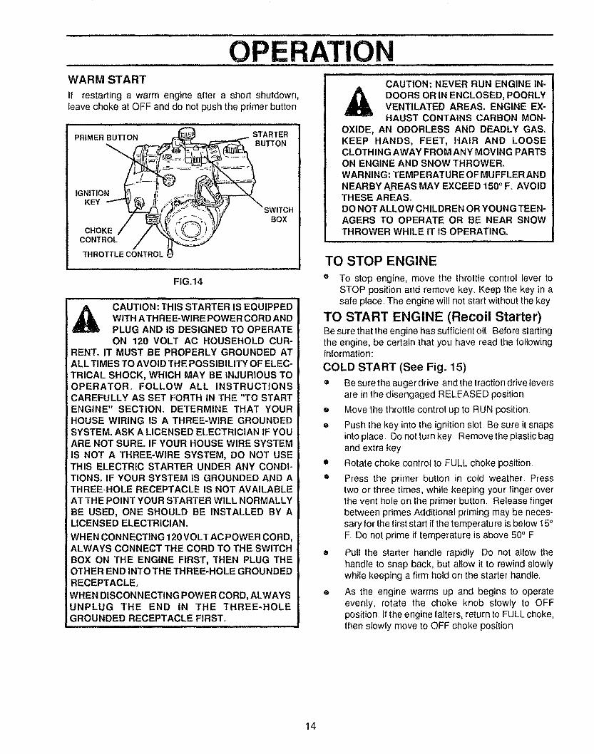
TIWARM S'rART
If restarting a warm engine after a short shutdown,leave choke at OFF and do not push the primer button
CAUTION: NEVER RUN ENGINE IN-DOORS OR IN ENCLOSED, POORLYVENTILATED AREAS. ENGINE EX-
FIG.14
HAUST CONTAINS CARBON MON-OXIDE, AN ODORLESS AND DEADLY GAS_KEEP HANDS, FEET, HAIR AND LOOSECLOTHING AWAY FROM ANY MOVING PARTSON ENGINE AND SNOW THROWER.WARNING: TEMPERATURE OF MUFFLERAND
NEARBY AREAS MAY EXCEED 150° F. AVOIDTHESE AREAS.DO NOT ALLOW CHILDREN OR YOUNG TEEN-AGERS TO OPERATE OR BE NEAR SNOWTHROWER WHILE IT IS OPERATING.
TO STOP ENGINE
® To stop engine, move the throttle control lever toSTOP position and remove key Keep the key in a
CAUT,0NiTH,SSTARTER,SEaU,PPE0W,THATHREE-WIREPOWERCORDANDPLUG AND iS DESIGNED TO OPERATE
ON 120 VOLT AC HOUSEHOLD CUR-
BEN'[.IT MUST BE PROPERLY GROUNDED ATALL TIMES TO AVOID THE POSSIBILITY OF ELEC-
TRICAL SHOCK, WHICH MAY BE INJURIOUS TO
safe peace The engine will not start without the key
TO START ENGINE (Recoil Starter)Be sure that the engine has sufficient oil Before startingthe engine, be certain that you have read the followinginformation:
COLD START (See Fig. 15)
OPERATOR_ FOLLOW ALL INSTRUCTIONSCAREFULLY AS SET FORTH IN THE "TO STARTENGINE" SECTION. DETERMINE THAT YOURHOUSE WIRING IS A THREE*WIRE GROUNDEDSYSTEM. ASK A LICENSED ELECTRICIAN tF YOUARE NOT SURE. IF YOUR HOUSE WIRE SYSTEMIS NOT A THREE-WIRE SYSTEM, DO NOT USETHIS ELECTRIC STARTER UNDER ANY CONDI-TIONS. IF YOUR SYSTEM IS GROUNDED AND A
THREEHOLE RECEPTACLE iS NOT AVAILABLEAT THE POINT YOUR STARTER WILL NORMALLYBE USED, ONE SHOULD BE INSTALLED BY ALICENSED ELECTRICIAN.
WHEN CONNECTING 120 VOLT AC POWER CORD,ALWAYS CONNECT THE CORD TO THE SWITCHBOX ON THE ENGINE FIRST, THEN PLUG THEOTHER END iNl"O THE THREE-HOLE GROUNDEDRECEPTACLE.
WHEN DISCONNECTING POWER CORD, ALWAYSUNPLUG THE END IN THE THREE-HOLEGROUNDED RECEPTACLE FIRST.
e Be sure the auger drive and the lraction drive leversare in the disengaged RELEASED position
,=, Move the throttle control up to RUN position
e Push the key into the ignition slot Be sure it snapsinto place Do not turn key Remove the plastic bagand extra key
• Rotate choke control to FULL choke position
® Press the primer button in cold weather Presstwo or three times, while keeping your finger overthe vent hole on the primer button. Release fingerbetween primes Additional priming may be neces-sary for the first start if the temperature is below 15°F Do not prime if temperature is above 50° F
• Pull the starter handie rapidly Do not allow thehandle to snap back, but allow it to rewind slowlywhile keeping a firm hold on the starter handle
e As the engine warms up and begins to operateevenly, rotate the choke knob slowly to OFFposition _tf the engine falters, return to FULL choke,then slowly move to OFF choke position
14
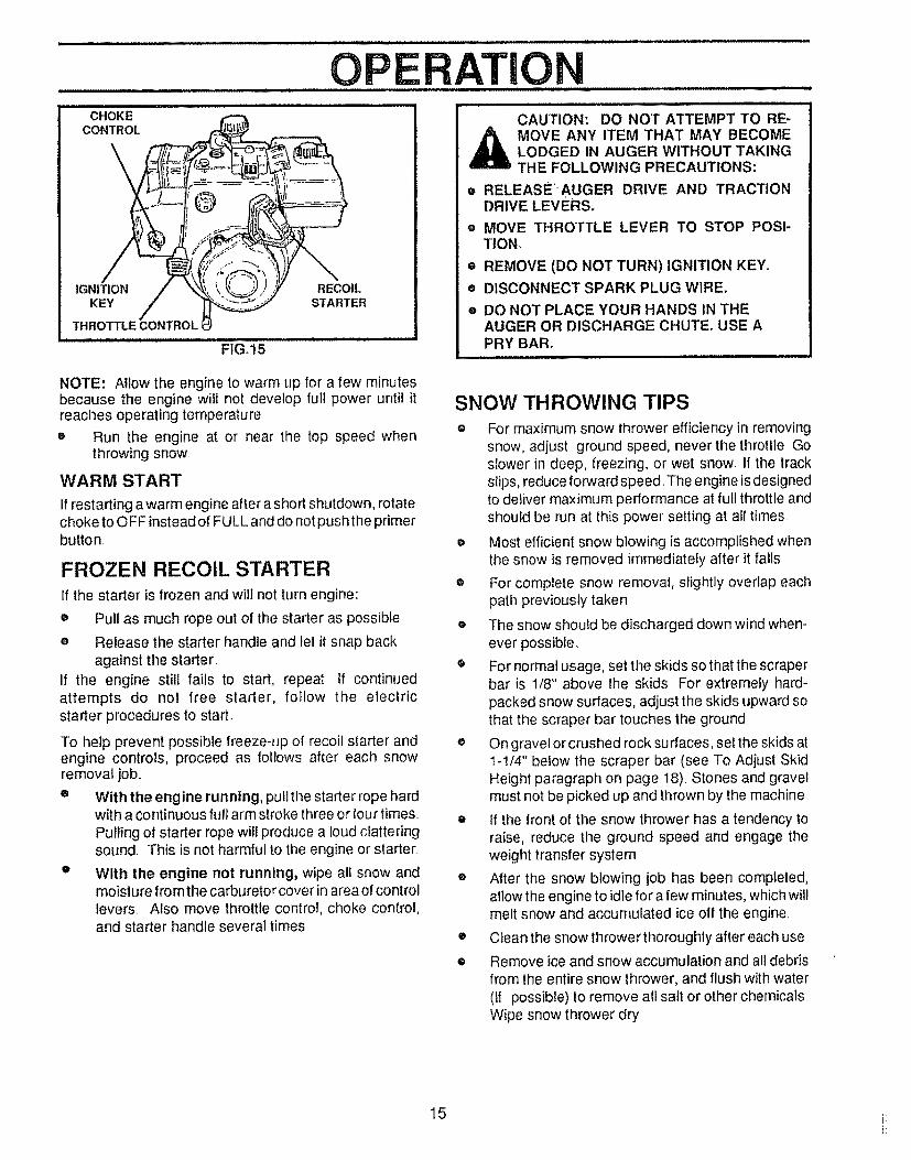
CHOKECONTROL
IGNITION RECOILKEY STARTER
THROTTLECONTROLI
FIG°15
O E TIONCAUTION: DO NOT ATTEMPT TO RE-MOVE ANY ITEM THAT MAY BECOMELODGED IN AUGER WITHOUT TAKINGTHE FOLLOWING PRECAUTIONS:
e RELEASE'_AUGER DRIVE AND TRACTIONDRIVE LEVERS,
® MOVE THROTTLE LEVER TO STOP POSI-TION,
• REMOVE (DO NOT TURN) IGNITION KEY.
• DISCONNECT SPARK PLUG WIRE.
® DO NOT PLACE YOUR HANDS IN THEAUGER OR DISCHARGE CHUTE. USE APRY BAR.
NOTE: Allow the engine to warm up for a few minutesbecause the engine will not develop full power until itreaches operating temperature.
SNOW THROWING TIPS
o Run the engine at or near the top speed whenthrowing snow
WARM START
If restarting awarm engine after a short shutdown, rotatechoke to OFF instead of FULL and do not push the primerbutton,
FROZEN RECOIL STARTER
If the starter is frozen and will not turn engine:
• Pull as much rope out of the starter as possible
e Release the starter handle and let it snap backagainst the starter
If the engine still fails to start, repeat If continuedattempts do not free starter, follow the electricstarter procedures to start.
To help prevent possible freeze-up of recoil starter andengine controls, proceed as follows after each snowremoval job..
e With the engine running, pull the starter rope hardwith a continuous full arm stroke three or four times.Pulling of starter rope will produce a loud clatteringsound Th{s is not harmful to the engine or starter_
e With the engine not running, wipe ali snow andmoisture from the carburetor cover in area of controllevers. Also move throttle control, choke control,and starter handle several times
® For maximum snow thrower efficiency in removingsnow, adjust ground speed, never the throttle Goslower in deep, freezing, or wet snow. If the trackslips, reduce forward speed. The engine is designedto deliver maximum performance at full throttle andshould be run at this power setting at all times.
o Most efficient snow blowing is accomplished whenthe snow is removed immediately after it falls
e For complete snow removal, slightly overlap eachpath previously taken
o The snow should be discharged down wind when-ever possible.
e For normal usage, set the skids so that the scraperbar is 1/8" above the skids For extremely hard-packed snow surfaces, adjust the skids upward sothat the scraper bar touches the ground
o On gravel or crushed rock sutraces, set the skids att-!/4" below the scraper bar (see To Adjust SkidHeight paragraph on page 18) Stones and gravelmust not be picked up and thrown by the machine
e If the front of the snow thrower has a tendency toraise, reduce the ground speed and engage theweight transfer system
o After the snow blowing job has been completed,allow the engine to idle for a few minutes, which willmelt snow and accumulated ice off the engine.
• Clean the snow thrower thoroughly after each use
• Remove ice and snow accumulation and all debrisfrom the entire snow thrower, and flush with water(if possible) to remove all salt or other chemicalsWipe snow thrower dry
15 i_
CUSTOMER RESPONSIBILITIESGENERAL RECOMMENDATIONS ..................
The warranty on this snow thrower does not cover itemsthat have been subjected to operator abuse or negli-gence, To receive full value from the warranty, operatormust maintain snow thrower as instructed in this manual
Some adjustments will need to be made periodically toproperly maintain your snow thrower.
All adjustments in the Service and Adjustments section ofthis manual should be checked at least once eachseason.
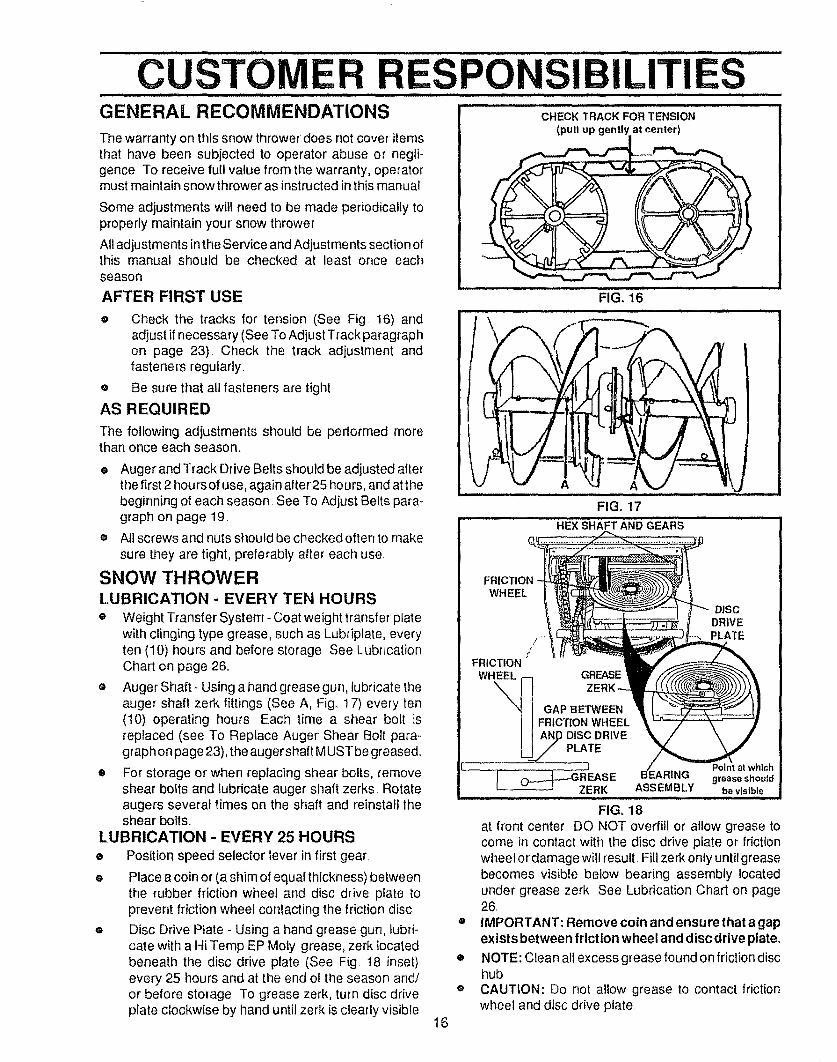
AFTER FIRST USE
e Check the tracks for tension (See Fig. 16) andadjust if necessary (See To Adjust Track paragraphon page 23). Check the track adjustment andfasteners regularly.
® Be sure that all fasteners are tight
AS REQUIRED
The following adjustments should be performed morethan once each season.
e Augerand Track Drive Belts should be adjusted afterthe first 2 hours of use, again after25 hours, and atthebeginning of each season See To Adjust Belts para-graph on page 19.
® All screws and nuts should be checked often to make
sure they are tight, preferably after each use
SNOW THROWERLUBRICATION - EVERY TEN HOURS
® Weight Transfer System- Coat weight transfer platewith clinging type grease, such as Lubriplate, everyten (10) hours and before storage See LubricationChart on page 26
• Auger Shaft- Using a hand grease gun, lubricate theauger shaft zerk fittings (See A, Fig.. 17) every ten(10) operating hours Each time a shear bolt isreplaced (see To Replace Auger Shear Bolt para-graph on page 23), the auger shaft MUST be greased..
® For storage or when replacing shear bolts, removeshear bolts and lubricate auger shaft zerks Rotateaugers several times on the shaft and reinstall theshear bolts_
LUBRICATION - EVERY 25 HOURS
e Position speed selector lever in first gear.
e Place a coin or (a shim of equal thickness) betweenthe rubber friction wheel and disc drive plate toprevent friction wheel contacting the friction disc
e Disc Drive Plate - Using a hand grease gun, lubri-cate with a Hi Temp EP Moly grease, zerk locatedbeneath the disc drive plate (See Fig 18 inset)every 25 hours and at the end of the season and/or before storage. To grease zerk, turn disc driveplate clockwise by hand until zerk is clearly visible
H ii
CHECK TRACK FOR TENSION
(pull up gently at center_._)
FIG. 16,i,, i iii ,Ll,,i llllll ,, ,_,,,_,, ,_,,
J/
A
FIG. 17
HEX SHAFT AND GEARS
WHEEL
!FRICTION
WHEEL GREASE
DISCDRIVEPLATE
GAP BETWEENFRICTION WHEEL
16
o
o
®
tchgrease shoutd
ASSEMBLY be visible.......... Ji ,, uu.,,,, l, ,i,i, ,u,,,u,
FIG, 18at front center DO NOT overfill o_ allow grease tocome in contact with the disc drive plate or frictionwheel ordamage will result Fill zerk only until greasebecomes visible below bearing assembly locatedunder grease zerk See Lubrication Chart on page26.
IMPORTANT: Remove coin and ensure that a gapexists between friction wheel and disc drive plate.
NOTE: Clean all excess grease found on friction dischubCAUTION: Do not allow grease to contact frictionwheel and disc drive plate.
CUSTOM SPO ILITIESLUBRICATION
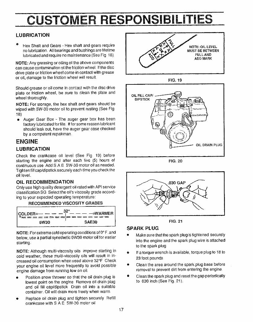
® Hex Shaft and Gears - Hex shaft and gears requireno lubrication. All bearings and bushings are lifetimelubricated and require no maintenance (See Fig t8)..
NOTE: Any greasing or oiling o! the above componentscan cause contamination of the friction wheel. If the disc
drive plate or friction wheel come in contact with greaseor oil, damage to the friction wheel will result
Should grease or oil come in contact with the disc driveplate or friction wheel, be sure to clean the plate andwheel thoroughly_
NOTE: For storage, the hex shaft and gears should bewiped with 5W-30 motor oil to prevent rusting (See Fig
• Auger Gear Box - The auger gear box has beenfactory lubricated for life. If for some reason lubricantshould leak out, have the auger gear case checkedby a competent repairman.
ENGINE
LUBRICATION
Check the crankcase oil level (See Fig t9) belorestarting the engine and after each five (5) hours ofcontinuous use_ Add S,AE. 5W-30 motor oil as needed..
Tighten fillcap/dipstick securely each time you check theoil level.
OIL RECOMMENDATIONOnly use high quality detergent oil rated with APt serviceclassification SG. Select the oil's viscosity grade accord-ing to your expected operating temperature:
RECOMMENDED VISCOSITY GRADES
ICOLDER. 5W30 32°I SAE30"WARMER
NOTE: For extreme cold operating conditions of 0° F. andbelow, use a partial synethetic 0W30 motor oil for easierstarting_
NOTE: Although multi-viscosity oils improve starting incold weather, these multi-viscosity oils will result in in-creased oi! consumption when used above 32°F Checkyour engine oil level more frequently to avoid possibleengine damage from running low on oil
e Position snow thrower so that the oil drain plug islowest point on the engine Remove oil drain plugand oil fill cap/dipstick Drain oil into a suitablecontainer. Oil will drain more freely when warm
o Replace oil drain plug and tighten securely Refillcrankcase with SAE 5W-30 motor oi!
I7
___NOTE: OIL LEVEL
.,,_,,p _ _.p..f,.T_]_v MUST BEBETWEEN
ADD MARK
FIG, 19
OIL FILL CAP/DIPSTICK
OIL DRAIN PLUG
FIG, 20
.030 GAP
FIGo 21
SPARK PLUG
e Make sure that the spark plug is tightened securelyinto the engine and the spark plug wire is attached
to the spark plug
e It a torque wrench is available, torque plug to 18 to
23 foot pounds.
• Clean the area around the spark plug base beforeremoval to prevent dirt from entering the engine
• Clean the spark plug and reset the gap periodicallyto 030 inch (See Fig.. 21)..
SERVICE AND ADJUSTMENTSi= i i lUl,,i i, ................................... Jl, i ii,i n i ill,ll ilU,,ll
CAUTION: ALWAYS DISCONNECT THESPARK PLUG WIRE AND TIE BACKAWAY FROM THE PLUG BEFORE MAK-ING ANY ADJUSTMENTS OR REPAIRS_
TO ADJUST SKID HEIGHT
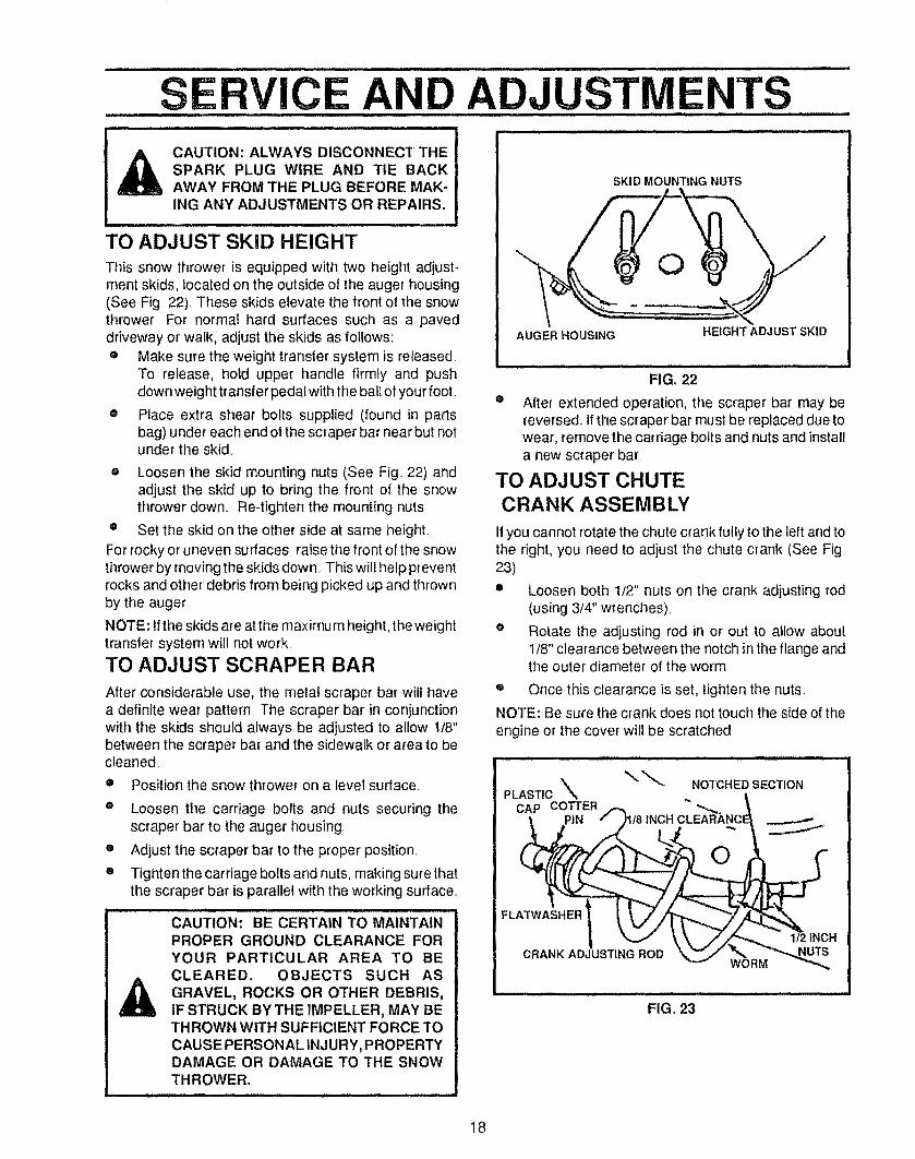
This snow thrower is equipped with two height adjust-ment skids, located on the outside of the auger housing(See Fig 22) These skids elevate the front of the snowthrower. For normal hard surfaces such as a paveddriveway or walk, adjust the skids as follows:® Make sure the weight transfer system is released.
To release, hotd upper handle firmly and pushdown weight transfer pedal with the ball of your foot.
® Place extra shear bolts supplied (found in partsbag) under each end of the scraper bar near but notunder the skid.,
e Loosen the skid mounting nuts (See Fig. 22) andadjust the skid up to bring the front of the snowthrower down. Re-tighten the mounting nuts.
e Set the skid on the other side at same height.
For rocky or uneven surfaces, raise the front of the snowthrower by moving the skids down, This will help preventrocks and other debris from being picked up and thrownby the auger
NOTE: If the skids are at the maximum height, the weighttransfer system will not work
TO ADJUST SCRAPER BAR
After considerable use, the metal scraper bar will havea definite wear pattern The scraper bar in conjunctionwith the skids should always be adjusted to allow 1t8"between the scraper bar and the sidewalk or area to becleaned
• Position the snow thrower on a level sudace_o
o
o
Loosen the carriage bolts and nuts securing thescraper bar to the auger housing,
Adjust the scraper bar to the proper position,
Tighten the carriage bolts and nuts, making sure thatthe scraper bar is parallel with the working surface.,
CAUTION: BE CERTAIN TO MAINTAIN
PROPER GROUND CLEARANCE FORYOUR PARTICULAR AREA TO BECLEARED. OBJECTS SUCH ASGRAVEL, ROCKS OR OTHER DEBRIS,IF STRUCK BY THE IMPELLER, MAY BETHROWN WITH SUFFICIENT FORCE TOCAUSE PERSONAL INJURY, PROPERTYDAMAGEORDAMAGETOTHESNOWTHROWER.
SKID MOUNTING NUTS
AUGER HOUSING HEIGHT ADJ UST SKID
FIGo 22
e After extended operation, the scraper bar may bereversed If the scraper bar must be replaced due towear, remove the carriage bolts and nuts and installa new scraper bar,
TO ADJUST CHUTECRANK ASSEMBLY
If you cannot rotate the chute crank fully to the left and tothe right, you need to adjust the chute crank (See Fig23)
e Loosen both 1/2" nuts on the crank adjusting rod(using 3/4" wrenches),
e Rotate the adjusting rod in or out to allow about1/8" clearance between the notch in the flange andthe outer diameter of the worm
= Once this clearance is set, tighten the nuts,
NOTE: Be sure the crank does not touch the side of theengine or the cover will be scratched
\ .OTCHEDSECT,ONPLASTIC ,%
CAP COTTERINCH CLEARANC
FLATWASHER 1
CRANK ADJUSTING ROD
1t2 INCH
FIG. 23
18
iiiii u,mlll ilul iJl i, ii iltllltl
S RViCE ANTO ADJUST THE CLUTCH CONTROL
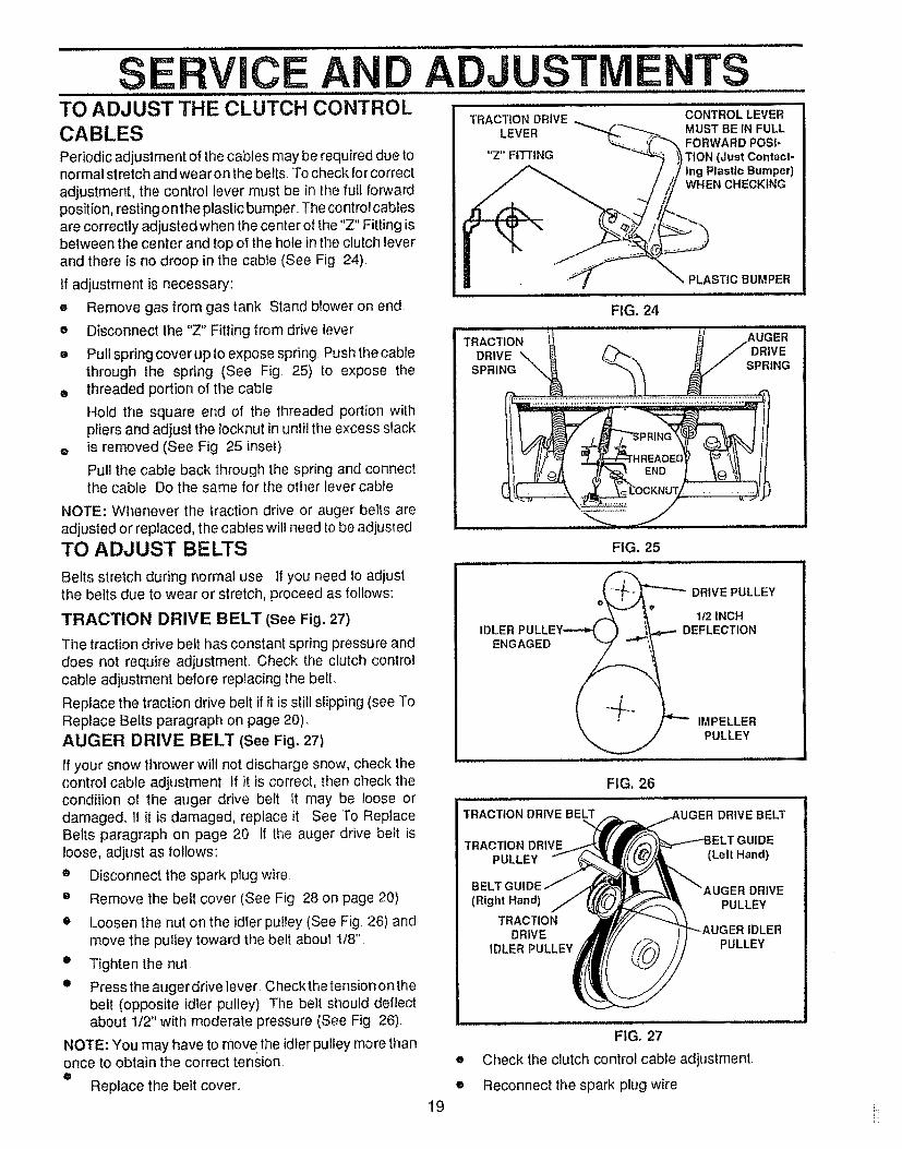
CABLESPeriodic adjustment of the cables may be required due tonormal stretch and wearon the belts, To check for correctadjustment, the control lever must be in the full forwardposition, resting o nthe plastic bumper+ The control cablesare correctly adjusted when the center of the "Z" Fitting isbetween the center and top of the hole in the clutch leverand there is no droop in the cable (See Fig 24)
If adjustment is necessary:
Remove gas from gas tank Stand blower on ende
e
o
Disconnect the "Z" Fitting from drive lever
Pull spring cover upto expose spring Push the cablethrough the spring (See Fig, 25) to expose the
o threaded portion of the cable
Hold the square end of the threaded portion withpliers and adjust the Iocknut in until the excess slack
e is removed (See Fig, 25 inset).
Pull the cable back through the spring and connectthe cable Do the same for the other lever cable
NOTE: Whenever the traction drive or auger belts areadjusted or replaced, the cables will need to be adjusted
TO ADJUST BELTS
Belts stretch during normal use If you need to adjustthe belts due to wear or stretch, proceed as follows:
TRACTION DRIVE BELT (See Fig. 27)
The traction drive belt has constant spring pressure anddoes not require adjustment, Check the clutch controlcable adjustment before replacing the belt.
Replace the traction drive belt if it is still slipping (see ToReplace Belts paragraph on page 20)_AUGER DRIVE BELT (See Fig. 27)
If your snow thrower will not discharge snow, check thecontrol cable adjustment If it is correct, then check thecondition of the auger drive belt It may be toose ordamaged., If it is damaged, replace it, See To ReplaceBelts paragraph on page 20 If the auger drive belt isloose, adjust as follows:
e Disconnect the spark plug wire
• Remove the belt cover (See Fig 28 on page 20)
• Loosen the nut on the idler pulley (See Fig, 26) andmove the pulley toward the bert about 1/8",
• Tighten the nut.
• Presstheaugerdrivelever Checkthetensiononthebelt (opposite idler pulley), The bett should deflectabout 1/2" with moderate pressure (See Fig, 26)+
NOTE: You may have to move the idler pulley more thanonce to obtain the correct tension.o
Replace the belt cover+
ADJUSTME TSTRACTION DRIVE
LEVER
"Z" FITTING
CONTROL LEVERMUST BE IN FULLFORWARD POSI-
TION (Just Contact-ing Plasllc Bumper)WHEN CHECKING
TRACTIONDRIVE
SPRING
FIG.+24
PLASTIC BUMPER
DRIVESPRING
1
IDLERENGAGED
FIG, 25
DRIVE PULLEY
1/2 INCHDEFLECTION
IMPELLERPULLEY
FIG, 26
TRACTION DRIVE BELT UGER DRIVE BELT
TRACTION DRIVE "GUIDEPULLEY (Left Hand)
BELT DRIVE(Right Hand) PULLEY
TRACTIONDRIVE IDLER
IDLER PULLEY PULLEY
19
FIG, 27
• Check the clutch control cable adjustment
• Reconnect the spark plug wire
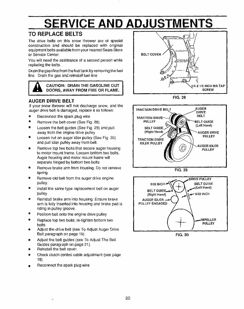
..............SERVICE,,,AN,D ADJUSTMENTSTO REPLACE BELTSThe drive belts on this snow thrower are of specialconstruction and should be replaced with originalequipment belts available from your nearest Sears Storeor Service Center,
You will need the assistance of a second person whilereplacing the belts.
Drain the gasoline from the fue! tank by removing the fuelline Drain the gas and reinstall fuel line
IA............. .......ICAUTION: DRAIN THE GASOLINE OUTDOORS, AWAY FROM FIRE OR FLAME.Jl,i ii,Jl,l,i, i iii iii H, i,,
AUGER DRIVE BELTif your snow thrower will not discharge snow, and theauger drive belt is damaged, replace it as follows:
® Disconnect the spark plug wire.
e Remove the belt cover (See Fig 28)
• Loosen the belt guides (See Fig 29) and pullaway from the engine drive pulley
® Loosen nut on auger idler pultey (See Fig 30)and pull idler pulley away from belt
• Remove top two bolts that secure auger housingto motor mount frame,, Loosen bottom two bolts,
Auger housing and motor mount frame willseparate hinged by bottom two bolts
e Remove brake arm from housing, Do not removespring
e Remove old belt from the auger drive enginepulley,,
e install the same type replacement belt on augerpulley
• Reinstall brake arm into housing, Ensure brakearm is fully inserted into housing and brake pad isriding in pulley groove,
® Position bell onto the engine drive pulley
® Replace top two bolts; re-tighten bottom twobolts
e Adjust the drive bett (see To Adjust Auger DriveBelt paragraph on page 19)
= Adjust the belt guides (see To Adjust The BeltGuides paragraph on page 21)
o Reinstall the belt cover,
i i1,111I,L
/
/
IILLI, III I II III
FIG. 28
I4 X 112 INCH WA TAPSCREW
wn,,
TRACTION DRIVE BELT AUGER
TRACTION BELT
PULLEY 3E
(Left Hand)BELT GUIDE
(Right Hand) DRIVEPULLEY
TRACTION DRIVEIDLER PULLEY
IDLERPULLEY
,,, i i,, i ii i ii ii
FIG. 29
,,,,
, , ,_,,..._ ..sDRIVE PULLEY3132INCH BELTGUIDE
BELT GUIDE..._ "'_'\ _ r''(Left Hand)
(Right Hand) A- ""_\_"_ 3/32 INCH
,...,,,IMPELLER
_ X-" ) PULLEY
FIG. 30
Check clutch control cable adjustment (see page19),
Reconnect the spark plug wire,
,, 20
S RVIC D ADJUSTME TSTRACTION DRIVE BELT
If your snow thrower will not move forward, check thetraction drive belt for wear, If the traction drive beltneeds to be replaced, proceed as follows:® Disconnect the spark plug wire,
• Remove the belt cover (See Fig, 28 on page 20)
e Loosen belt guides (See Fig 29) and pull beltguides away from the engine drive pulley.
e Loosen nut on auger idler and pull auger idlerpulleyaway from belto
® Remove auger drive belt from engine pulley,
e Pull drive belt idler pulley away from ddve belt® Remove drive belt
e Position new drive belt onto traction pulley
® Pul! idler pulley away from belt, allowing beit to bepositioned onto engine pulley.
e ReSease idJerpuJley Ensure _Jer puJJeyis properlyengaged with belt,
o Reinstall auger drive belt,
• Adjust belt guides (see To Adjust The Belt Guidesparagraph below),
® Adjust idler on auger belt,
e Reinstall the belt cover
o Reconnect the spark plug wire,
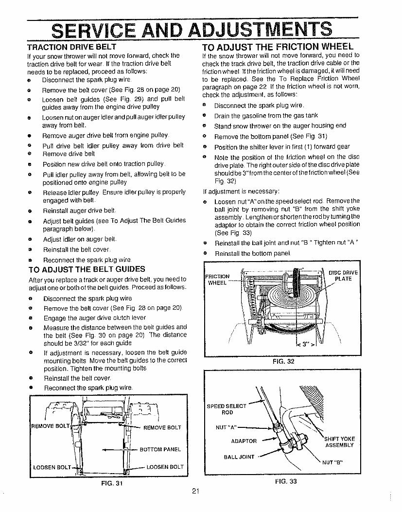
"1"OADJUST THE BELT GUIDES
Alter you replace a track or auger drive belt, you need toadjust one or both of the belt guides Proceed as lollows:
• Disconnect the spark plug wire.
e Remove the belt cover (See Fig 28 on page 20)
e Engage the auger drive clutch lever
• Measure the distance between the belt guides andthe belt (See Fig 30 on page 20) The distanceshould be 3/32" for each guide
o it adiustment is necessary, loosen the belt guidemounting bolts Move the belt guides to the correctposition., Tighten the mounting bolts
• Reinstall the belt cover,
• Reconnect the spark plug wire
FIG., 31
REMOVE BOLT,
LOOSEN BOLT,
TO ADJUST THE FRICTION WHEELIf the snow thrower will not move forward, you need tocheck the track drive belt, the traction drive cable or thefriction wheel If the friction wheel is damaged, it will needto be replaced, See the To Replace Friction Wheelparagraph on page 22 If the friction wheel is not worn,check the adjustment, as follows:
e Disconnect the spark plug wire,
e Drain the gasoline from the gas tank
® Standsnow thrower on the auger housing end
® Remove the bottom panel (See Fig. 31),
® Position the shifter lever in first (1) forward gear
e Note the position of the friction wheel on the discdrive plate,, The right outer side of the disc drive plateshould be 3" from the center of the friction wheel (SeeFig 32)
;I adjustment is necessary:
e Loosen nut "A" on the speed select rod Removetheball joint by removing nut "B" from the shift yokeassembly Lengthen or shortenthe rod by turning theadaptor to obtain the correct friction wheel position(See Fig 33),
e Reinstall the ball joint and nut "B" Tighten nut "A"
• Reinstall the bottom panel
FRICTION DISC DRIVEPLATE
FIG,, 32
21
SPEED SELECTROD
NUT"A"
ADAPTOR
BALL JOINT
FIG, 33
YOKEASSEMBLY
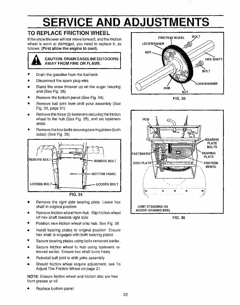
SERVICE AND ADJUSTMENTS ..............TO REPLACE FRICTION WHEELIf the snow thrower will not move forward, and the frictio nwheel is worn or damaged, you need to replace it, asfollows: (First allow the engine to cool).
CAUTION: DRAINGASOLINEOUTDOORS IAWAY FROM FIRE OR FLAME.
® Drain the gasoline from the fuel tank.
• Disconnect the spark plug wire
e Stand the snow thrower up on the auger housingend (See Fig. 36).
• Remove the bottom panel (See Fig. 34)_
• Remove ball joint from shift yoke assembly (SeeFig., 33, page 2i).
• Remove the three (3) fasteners securing the frictionwheel to the hub (See Fig. 35), and set fastenersaside
® Remove the four bofts securing bearing plates (bothsides) (See Fig. 36)
FIG. 34
® Remove the right side bearing plate Leave hexshaft in original position.
e Remove friction wheel from hub. Slip friction wheeloff hex shaft towards right side.
• Position new friction wheel onto hub. See Fig 36
Install bearing pfates to original position Ensurehex shaft is engaged with both bearing plates
• Secure bearing plates using bolts removed earlier.
• Secure friction wheel to hub using fasteners re-moved earlier. Ensure hex shaft turns freely
= Reinstall ball joint to shift yoke assembly.
• Should friction wheel require adjustment, see ToAdjust The Friction Wheel on page 21
DISC
FRtCTtO WHEEL
LOCKWASHER
BOLT
HEX SHAFT
BOLT
HUBNUT
FIG. 35
HUB
PLATEBOLTS
PLATE
FRICTION
.....,..,\. WHEEL
ir i
(UNIT STANDING ONAUGER HOUSING END)
FIG_ 36
NOTE: Ensure friction wheel and friction disc are freefrom grease or oil.
e Replace bottom panel
22
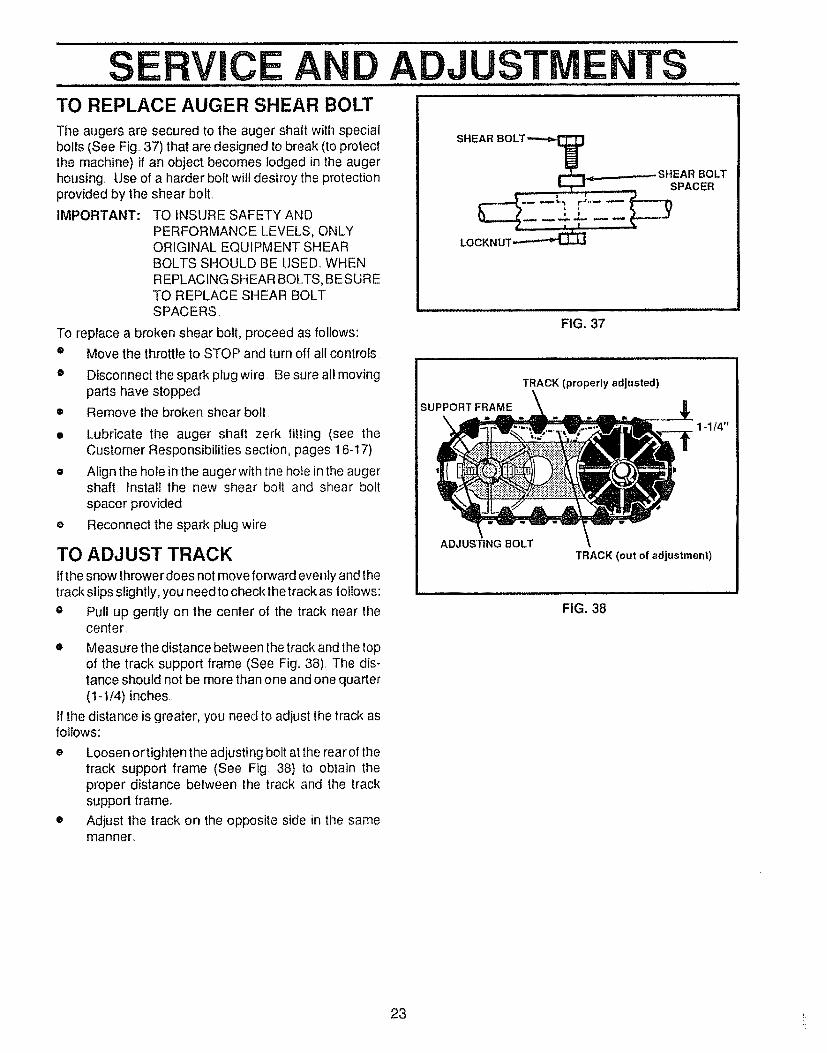
S RVIC ATO REPLACE AUGER SHEAR BOLTThe augers are secured to the auger shaft with specialbolts (See Fig..37) that are designed to break (to protectthe machine) if an object becomes lodged in the augerhousing Use of a harder bolt will destroy the protectionprovided by the shear bolt.
IMPORTANT: TO INSURE SAFETY ANDPERFORMANCE LEVELS, ONLYORIGINAL EQUIPMENT SHEARBOLTS SHOULD BE USED_ WHENREPLACING SHEAR BOLTS, BESURETO REPLACE SHEAR BOLTSPACERS.
To replace a broken shear bolt, proceed as follows:
Move the throttle to STOP and turn off all controls
Disconnect the spark plug wire Be sure all movingparts have stopped
Remove the broken shear boil
Lubricate the auger shaft zerk fitting (see theCustomer Responsibilities section, pages 16-17)
Afign the hole in the auger with the hole in the augershaft, install the new shear bolt and shear bolt
spacer provided
Reconnect the spark plug wire
O
O
o
o
TO ADJUST TRACKIfthe snow throwerdoes not move forward evenly and thetrack slips slightly, you need to check the track as follows:
® Pull up gently on the center of the track near thecenter.
• Measure the distance between the track and the topof the track support frame (See Fig.. 38). The dis-tance should not be more than one and one quarter(1-I/4) inches.
If the distance is greater, you need to adjust the track asfollows:
e Loosen or tighten the adjusting bolt at the rear of thetrack support frame (See Fig 38) to obtain theproper distance between the track and the tracksupport frame.
• Adjust the track on the opposite side in the samemanner.
ADJUSTME TS
LOCKNUT_
FIG. 37
TRACK (properly adjusted)
SUPPORT FRAME
ADJUSTING BOLT
1-1/4"
TRACK (out of adjustment)
FIG. 38
23 i_
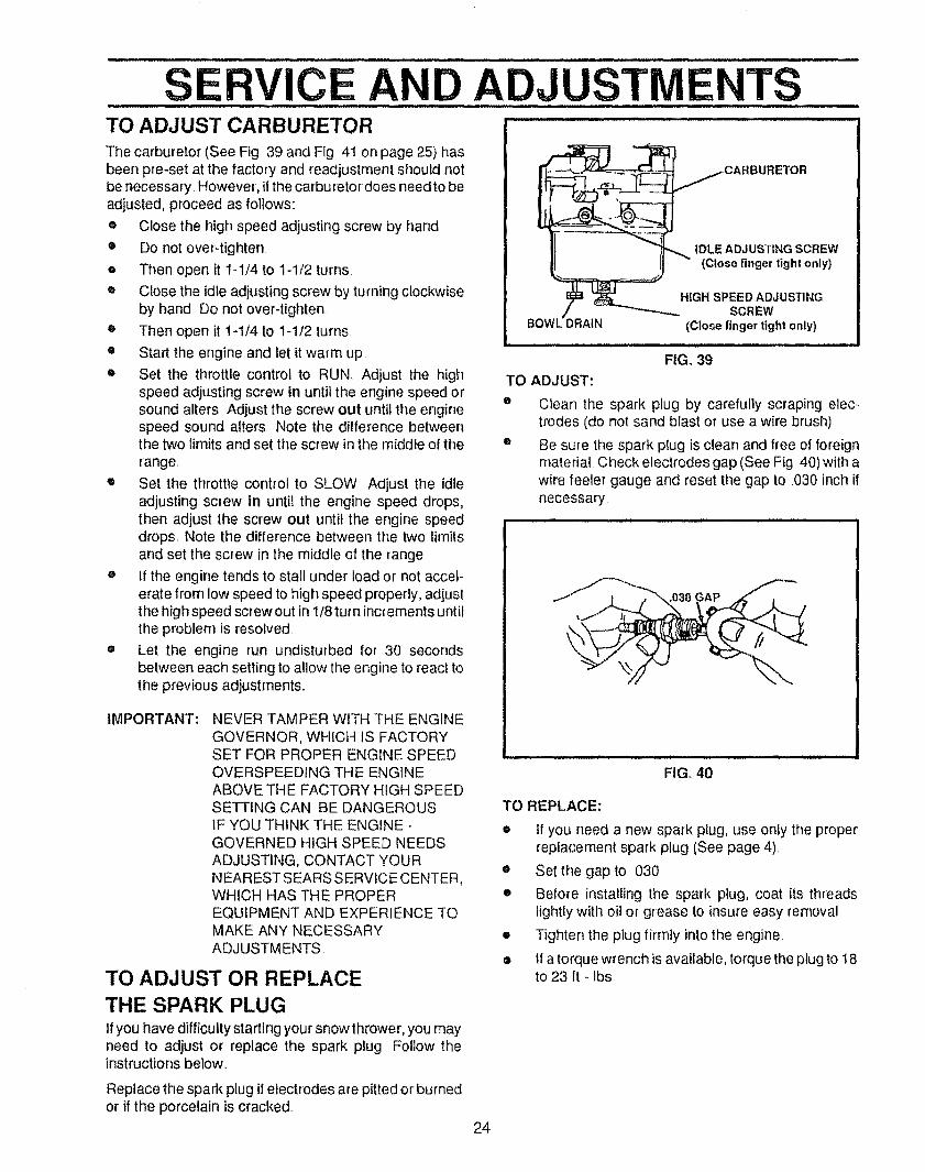
............SERVICE AND ADJUSTMENTS ......TO ADJUST CARBURETOR " .............
The carburetor (See Fig, 39 and Fig, 41 on page 25) hasbeen pre-set at the factory and readjustment should notbe necessary, However, if the carburetor does needto beadjusted, proceed as follows:
e Close the high speed adjusting screw by hand
• Do not over-tighten,
e Then open it 1-1/4 to 1-1/2 turns•
® Close the idle adjusting screw by turning clockwiseby hand, Do not over-tighten,
e Then open it 1-1/4 to 1-1/2 turns
• Start the engine and let it warm up
e Set the throttle control to RUN Adjust the highspeed adjusting screw in until the engine speed orsound alters, Adjust the screw out until the enginespeed sound alters Note the difference betweenthe two limits and set the screw in the middle of the
range
e Set the throttle control to SLOW Adjust the idleadjusting screw in until the engine speed drops,then adjust the screw out until the engine speeddrops_ Note the difference between the two limitsand set the screw in the middle of the range
® if the engine tends to stall under load or not accel-erate from low speed to high speed properly, adjustthe high speed screw out in 1/8 turn increments untilthe problem is resolved
e Let the engine run undisturbed for 30 secondsbetween each setting to allow the engine to react tothe previous adjustments,,
IMPORTANT: NEVER TAMPER WITH THE ENGINEGOVERNOR, WHICH IS FACTORYSET FOR PROPER ENGINE SPEED,OVERSPEEDING THE ENGINEABOVE THE FACTORY HIGH SPEEDSETTING CAN BE DANGEROUSIF YOU THINK THE ENGINE-GOVERNED HIGH SPEED NEEDSADJUSTING, CONTACT YOURNEARESTSEARS SERVICE CENTER,WHICH HAS THE PROPEREQUIPMENT AND EXPERIENCE TOMAKE ANY NECESSARYADJUSTMENTS
TO ADJUST OR REPLACETHE SPARK PLUGIf you have difficulty starting your snow thrower, you mayneed to adjust or replace the spark plug Follow theinstructions below.,
Replace the spark plug if electrodes are pitted or burnedor if the porcelain is cracked,.
IDLE ADJ USTING SCREW
(Close finger tight only)
HIGH SPEED ADJUSTINGSCREW
(Close finger tight only)
i L, ill ,i, •
FIG. 39TO ADJUST:
Q
Clean the spark plug by carefully scraping elec-trodes (do not sand blast or use a wire brush),
Be sure the spark plug is clean and free of foreignmaterial Check electrodes gap (See Fig 40) witt_awire feeler gauge and reset the gap to .030 inch itnecessary
FIG, 40
TO REPLACE:
• if you need a new spark plug, use onfy the properreplacement spark piug (See page 4),
e Set the gap to ,030
o Before installing the spark plug, coat its threadslightly with oil or grease to insure easy removal
• Tighten the plug firmly into the engine,
• If a torque wrench is available, torque the plug to 18to 23 ft - Ibs,
24
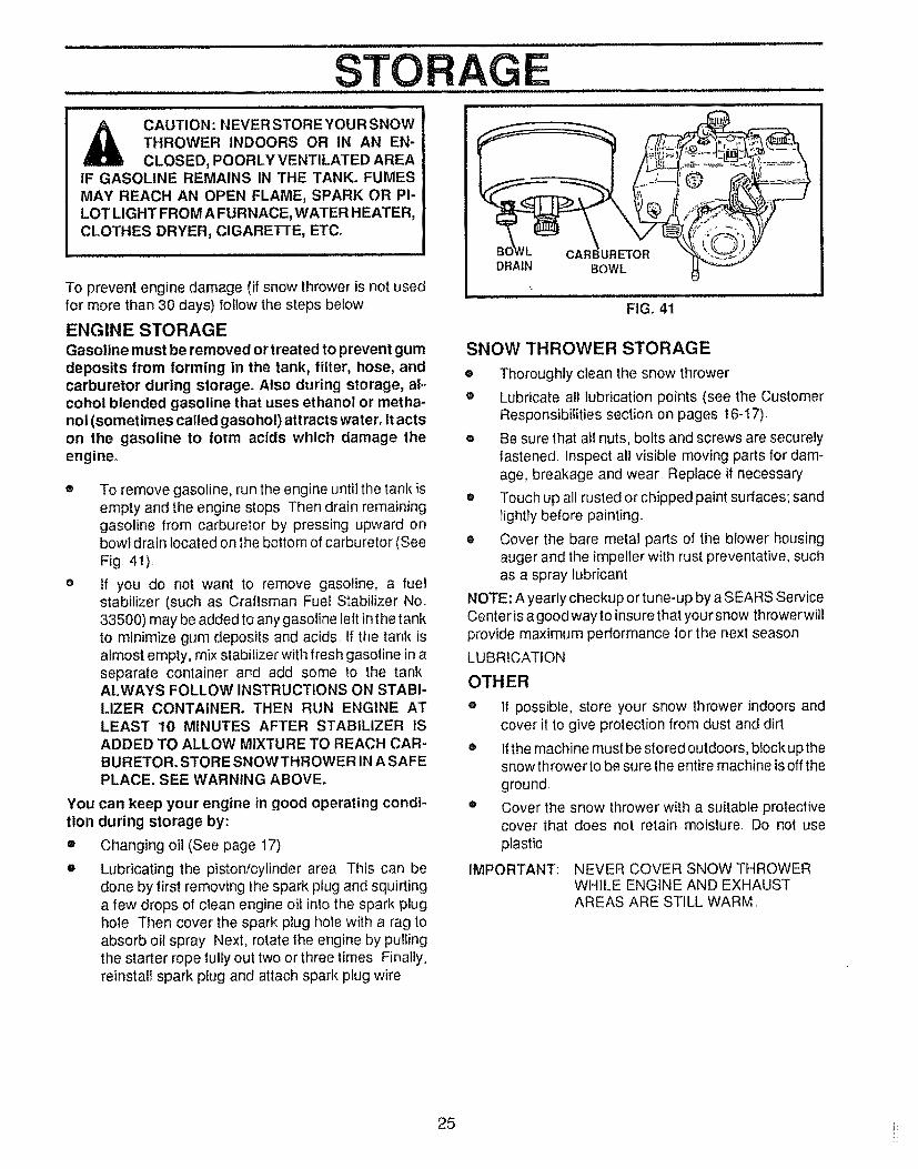
CAUTION : NEVER STORE YOUR SNOWTHROWER INDOORS OR IN AN EN-
CLOSED, POORLY VENTILATED AREAIF GASOLINE REMAINS IN THE TANK. FUMESMAY REACH AN OPEN FLAME, SPARK OR PI-LOT LIGHT FROM A FURNACE, WATER H EATER,CLOTHES DRYER, CIGARETTE, ETC,
To prevent engine damage (if snow thrower is not usedfor more than 30 days) follow the steps below.
ENGINE STORAGEGasoline must be removed or treated to prevent gumdeposits from forming in the tank, filter, hose, andcarburetor during storage. Also during storage, al-cohol blended gasoline that uses ethanol or metha-nol (sometimes called gasohol) attracts water. It actson the gasoline to form acids which damage theengine.
Yoution
®
O
To remove gasoline, run the engine until the tank isempty and the engine stops Then drain remaininggasoline from carburetor by pressing upward onbowl drain located on the bottom of carburetor (SeeFig 41)
If you do not want to remove gasoline, a fuelstabilizer (such as Craftsman Fuel Stabilizer No.33500) may be added to any gasoline left in the tankto minimize gum deposits and acids. If the tank isalmost empty, mix stabilizer with fresh gasoline in aseparate container and add some to the tank..ALWAYS FOLLOW INSTRUCTIONS ON STABI-LIZER CONTAINER. THEN RUN ENGINE ATLEAST 10 MINUTES AFTER STABILIZER IS
E
DRAIN
i i ,ll .l= i=,
BOWL
FIG. 41
SNOW THROWER STORAGE
e Thoroughly clean the snow thrower
® Lubricate all lubrication points (see the CustomerResponsibilities section on pages 16-17),
o Be sure that all nuts, bolts and screws are securelyfastened Inspect all visible moving parts for dam-age, breakage and wear Replace if necessary
• Touch up all rusted or chipped paint surfaces; sandlightly before painting
e Cover the bare metal parts of the blower housingauger and the impeller with rust preventative, suchas a spray lubricant
NOTE: A yearly checkup or tune-up by a SEARS ServiceCenter is a good way to insure that your snow throwerwi]lprovide maximum performance for the next season
LUBRICATION
OTHER
ADDED TO ALLOW MIXTURE TO REACH CAR-BURETOR. STORE SNOWTHROWER IN A SAFEPLACE. SEE WARNING ABOVE,
can keep your engine in good operating condi-during storage by:
Changing oil (See page 17),
If possible, store your snow thrower indoors andcover it to give protection from dust and dirt
Lubricating the piston/cylinder area This can bedone by first removing the spark plug and squirtinga few drops of clean engine oi! into the spark plughole. Then cover the spark plug hole with a rag toabsorb oil spray_.Next, rotate the engine by pullingthe starter rope fully out two or three times Finally,reinstall spark plug and attach spark plug wire..
o If the machine must be stored outdoors, block up thesnow thrower to be sure the entire machine is off theground
e Cover the snow thrower with a suitable protectivecover that does not retain moisture. Do not useplastic
NEVER COVER SNOW THROWERWHILE ENGINE AND EXHAUSTAREAS ARE STILL WARM.
IMPORTANT:
25 i_
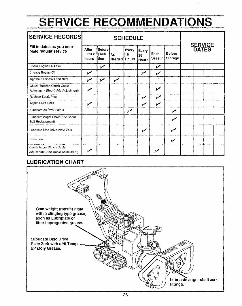
SE CE ECOMIVlENDATIONSSERVICE RECORDS SCHEDULE
SERVICEDATES
ii i ,i....
Fill in dates as you com-plete regular service After Before Every Every
First 2 Each As [10 25 Each Before
hours Use Needed Hours Hours Season Storage
Check Engine Oil Level f,_
Change Engine Oil _ _,4 _t
Tighten All Screws and Nuts /,J f_ /
:'Check Traction clutch Cabie .......................
Adjustment (See Cable Adjustment} /_r f._
Replace Spark Plug ............ / /_
:Adjustari,,ea_lts i," I," ..... v" ...................... = ..... : • : : a ................ : : :
Lubricate All Pivot Points _ pj
LubriCate Auger Shall iSee Shear
Bolt Replacement) ............ I.......
Lubricate Disc Drive Plate Zerk
Drain Fuel
Check Auger Clutch Cable
Adjustment (See Cable Adjustment) i/' It
1,1 11
i,,"
LUBRICATION CHART
Coat weight transfer platewith a clinging type grease,such as Lubriplate orfiber impregnated grease.
Lubricate Disc Drive
Plate Zerk with a Hi TempEP Moly Grease.
Lubricate auger shaft zerkfittings,
26
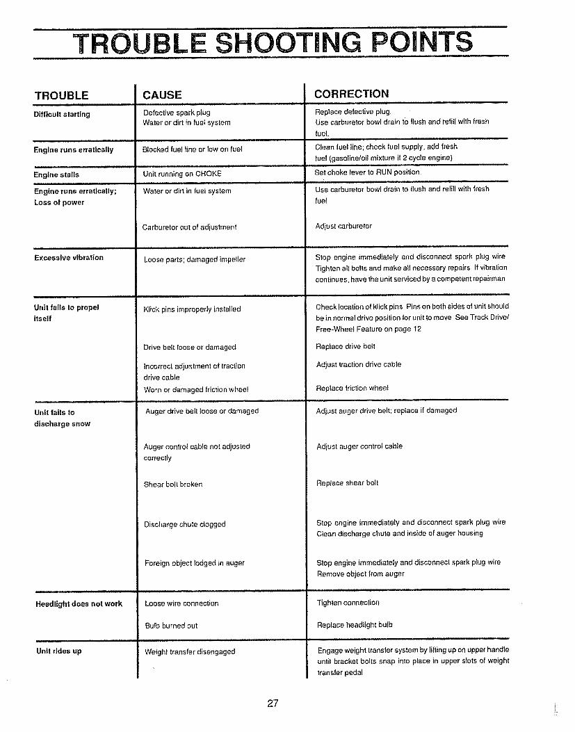
TROU L S OOTING POIJ J i
TS
TROUBLE
Difflcull starting
Engine runs erratically
Engine stalls
Engine runs erratically;
Loss of power
Excessive vibration
Unit fails to propel
itself
Unit fails to
discharge snow
CAUSE
Defective spark plug
Water or dirt in fuel system
Blocked fuef line or low on fuel
Unit running on CHOKE
Water or dirt in fuel system
Carburetor out of adjustment
Loose parts; damaged impeller
Klick pins improperly installed
Drive belt loose or damaged
Incorrect adjustment of tractiondrive cable
Worn or damaged triction wheel
Auger drive belt loose or damaged
Auger control cable not adjusted
CORRECTION
Replace defective plugUse carburetor bowl drain to flush and refill with fresh
fuel,
Clean fuel line; check fuel supply; add fresh
fuel (gasolineloil mixture if 2 cycle engine)
Set choke lever to RUN position
Use carburetor bowl drain to flush and refill with fresh
fuel
Adjust carburetor
Stop engine immediately and disconnect spark plug wire
Tighten all bolts and make all necessary repairs If vibration
continues, have the unit serviced by a competent repairman
Check location of klick pins Pins on both sides of unit should
be in normal drive position for unit to move See Track Drivel
Free+Wheel Feature on page 12
Replace drive belt
Adjust traction drive cable
Replace friction wheel
Adjust auger drive belt; replace if damaged
Adjust auger control cable
correctly
Shear bolt broken
Discharge chute clogged
Replace shear bolt
Stop engine immediately and disconnect spark plug wire
CIean discharge chute and inside of auger housing
Headlight does not work
Unit rides up
Foreign object lodged in auger
Loose wire connection
Bulb burned out
Weight transfer disengaged
Stop engine immediately and disconnect spark plug wire
Remove object from auger
Tighten connection
Replace head+ight bulb
Engage weight transfer system by lilting up on upper handle
until bracket bolls snap into place in upper slots of weight
transler pedal
27 i:
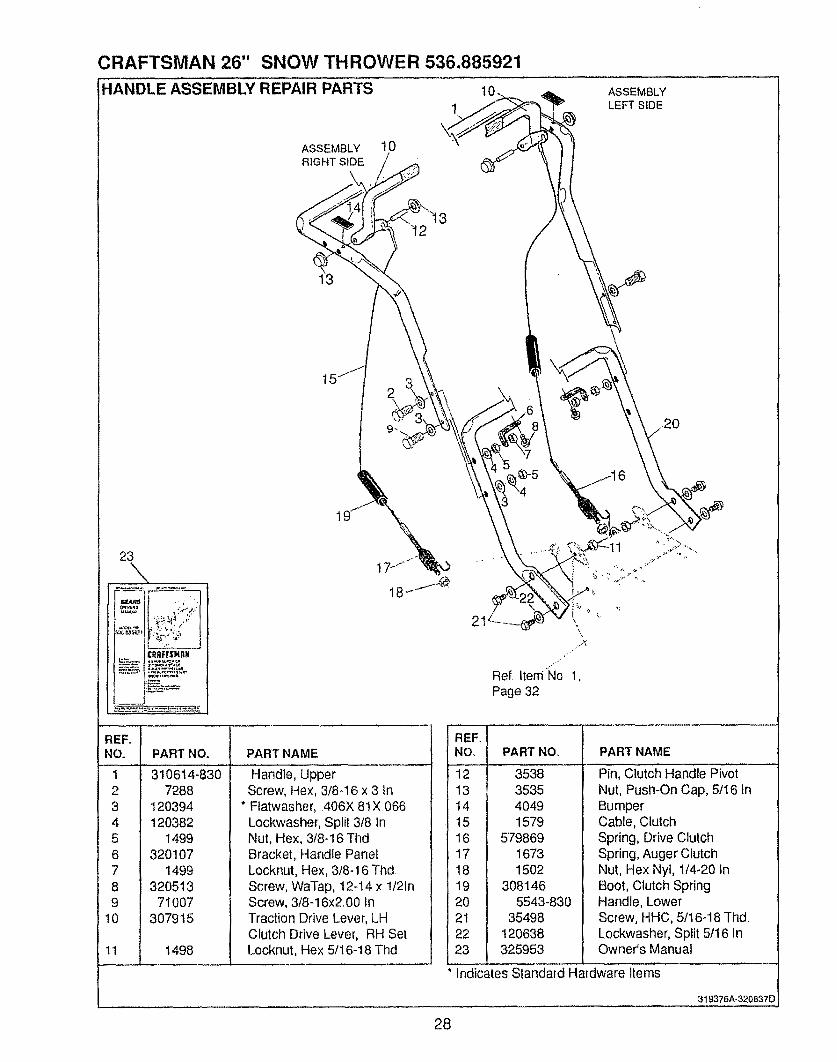
CRAFTSMAN 26" SNOW THROWER 536.885921
-IANDLE ASSEMBLY REPAIR PARTS 1o
1ASSEMBLYLEFT SIDE
ASSEMBLY 10RIGHT SIDE /
23
-tI
PART NAME
\
Ref Item_lo 1,
Page 32
"EFIINO. I
34
PART NO.
310614-8307288
120394120382
1499320107
149932051371007
307915
i498
Handle, UpperScrew, Hex, 3/8-16 x 3 In
* Ftatwasher, 406X 81X066Lockwasher, Split 3/8 InNut, Hex, 3/8-16 ThdBracket, Handle PanelLocknut, Hex, 3/8-I6 ThdScrew, WaTap, t2-14 x 1/21nScrew, 3/8-16x2 00 InTraction Drive Lever, LHClutch Drive Lever, RH SetLocknut, Hex 5/16-18 Thd
REENO.
121314151617181920212223
PART NOo
3538353540491579
57986916731502
3081465543-830
35498120638325953
PART NAME
Pin, Clutch Handle PivotNut, Push-On Cap, 5/16 InBumperCable, ClutchSpring, Drive ClutchSpring, Auger ClutchNut, Hex Nyt, 114-20 InBoot, Clutch SpringHandle, LowerScrew, HHC, 5fl 6-18 ThdLockwasher, Split 5/16 inOwner's Manual
Indicates Standard Hardware Items,
319376A-320637D
28
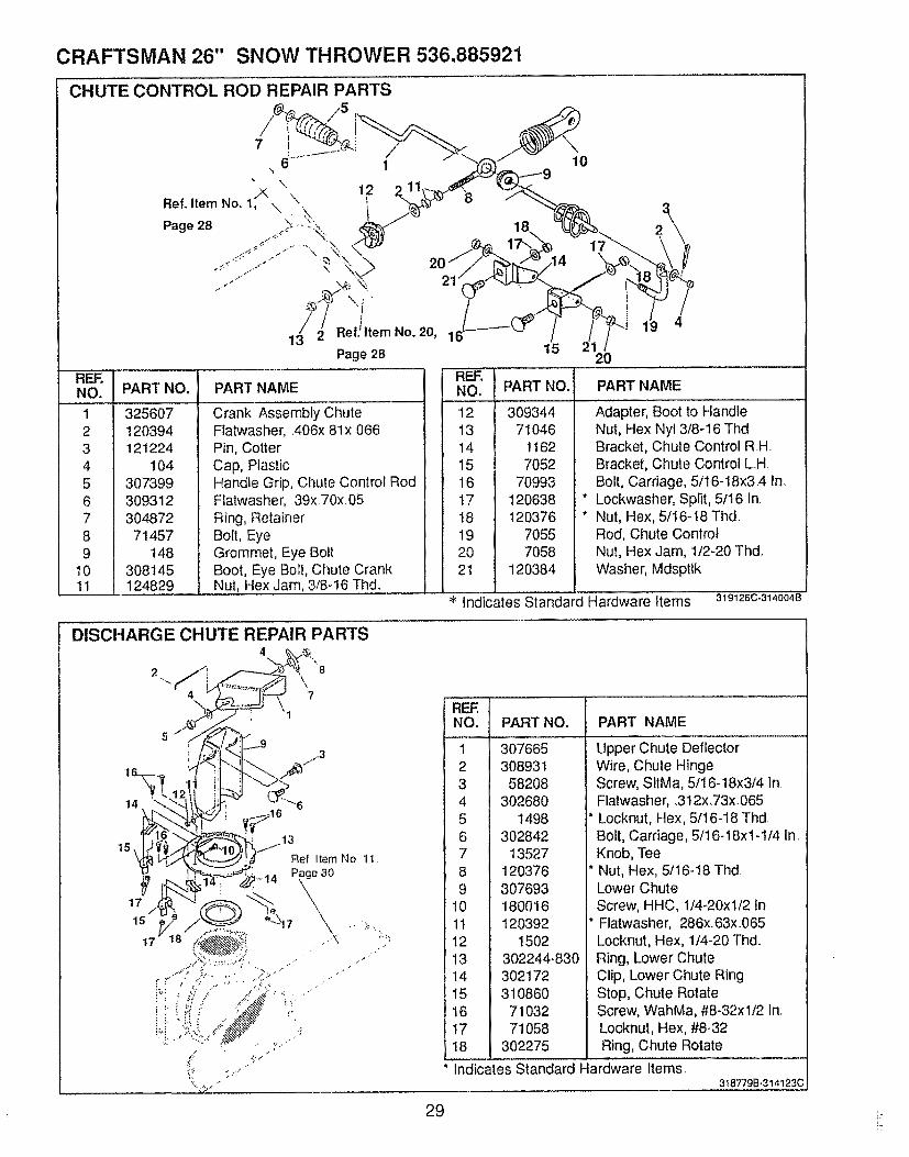
CRAFTSMAN 26" SNOW THROWER 536.885921
CHUTE CONTROL ROD REPAIR PARTS
REF.NO, PART NO,
1 3256072 1203943 1212244 1045 3073996 3093127 3048728 714579 148
10 308t 4511 124829
76 1 10
RefoltemNo,. 1_\ \. 12 2.. 8 3p.go28 . 1- 18. =\,,
,"_ _ 17",, 17
13//2 ReflltemN° 20' 1 15 21 /Page 28 20
............. REFoPART NAME NO. PART NO.
Crank Assembly ChuteFIatwasher, .406>:.81x 066Pin, CotterCap, PlasticHandle Grip, Chute Control RodFlatwasher, 39x70x 05Ring, RetainerBolt, EyeGrommet, Eye BoltBoot, Eye Bolt, Chute CrankNut, Hex Jam, 3/8-t6 Thd.
12 30934413 7104614 116215 705216 7099317 12063818 12037619 705520 705821 120384
it
it
PART NAME
Adapter, Boot to HandleNut, Hex Nyl 3/8-16 ThdBracket, Chute Control R.H.Bracket, Chute Control LHBolt, Carriage, 5/16-18x3,4 InLockwasher, Split, 5/16 In.Nut, Hex, 5/16-18 Thd.Rod, Chute ControlNut, Hex Jam, 1/2-20 Thd.Washer, Mdsptlk
'i<'i'ndicates s iandard Hardware items.. 319126c.314OO4B
DISCHARGE CHUTE REPAIR PARTS4 £X;r_,
Is_._ I" Re)I_mNo11,
_:J"_"-_ _.-,...._i _ ..... Page 30
\,V. ......:.......7 \ ,:.......
....../";'.":>.':>': ...... T d_
;,,- 27,.-"
REF, 1NO. t
*,J )
4 f
6 I
PART NO. PART NAME
307665308931
58208302680
1498302842
13527120376307693180016120392
1502302244-830302172310860
7103271058
302275
8 I
9 I10 I11 I
12 I
13 114 I
15 I
16 I17 I
18 I
Indicates Standard Hardware Items.
tipper Chute DeflectorWire, Chute HingeScrew, SltMa, 5/16-18x3/4 InFlatwasher, .312x,73xO65
* Locknut, Hex, 5/I6-18 ThdBolt, Carriage, 5/16-18xl-1/4 In.Knob, Tee
* Nut, Hex, 5/16-18 ThdLower Chute
i Screw, HHC, 114-20xl/2 tni* Flalwasher, 286x.63xO65
Locknut, Hex, 1/4-20 Thd.Ring, Lower ChuteClip, Lower Chute RingStop, Chute RotateScrew, WahMa, #8-32x112 In.Locknut, Hex, #8-32Ring, Chute Rotate
318779B-314123C
29
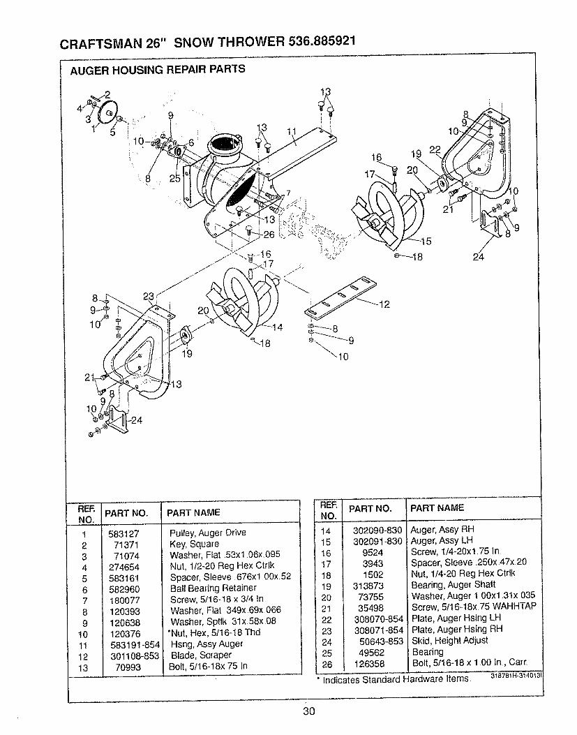
CRAFTSMAN 26" SNOW THROWER 536.885921
AUGER HOUSING REPAIR PARTS
9
10"]_19 22/_/
e-"_l 8 24
10/e
3
REF.NO.
I
2
3
4
5
67
8
9
10
11
12
13
PART NO. PART NAME
5831277137171074
274654583161582960180077120393120638120376583191-854301108-85370993
Pulley, Auger DriveKey, SquareWasher, Ffat .53xl .06x,095Nut, 112-20 Reg Hex CtrtkSpacer, Sleeve. 676x 1 00x. 52Ball Bearing RetainerScrew, 5/16-18 x 3/4 InWasher, Flat 349x.69x.066Washer, Sptlk 31x 58x 08
*Nut, Hex, 5116-18 ThdHsng, Assy AugerBlade, Scraper
Bolt, 5116-18x 75 In
1415t617181920212223242526
PART NO.
302090-830302091-830
952439431502
3138737375535498
308070-854308071-85450643-85349562
126358
PART NAME
Auger, Assy RHAuger, Assy LHScrew, 1/4-20xl.75 In.Spacer', Sleeve. 250x 47x 20Nut, 1/4-20 Reg Hex CtrlkBearing, Auger ShaftWasher, Auger 1.00xl .31x035Screw, 5t16-18x. 75 WAHHTAPPlate, Auger Hsing LHPlate, Auger Hsing RHSkid, Height AdjustBearingBolt, 5/16-18 x 1.00 in., Cart.
" Indicates Standard Hardware Items, 3t8781H.3t40!3!
30
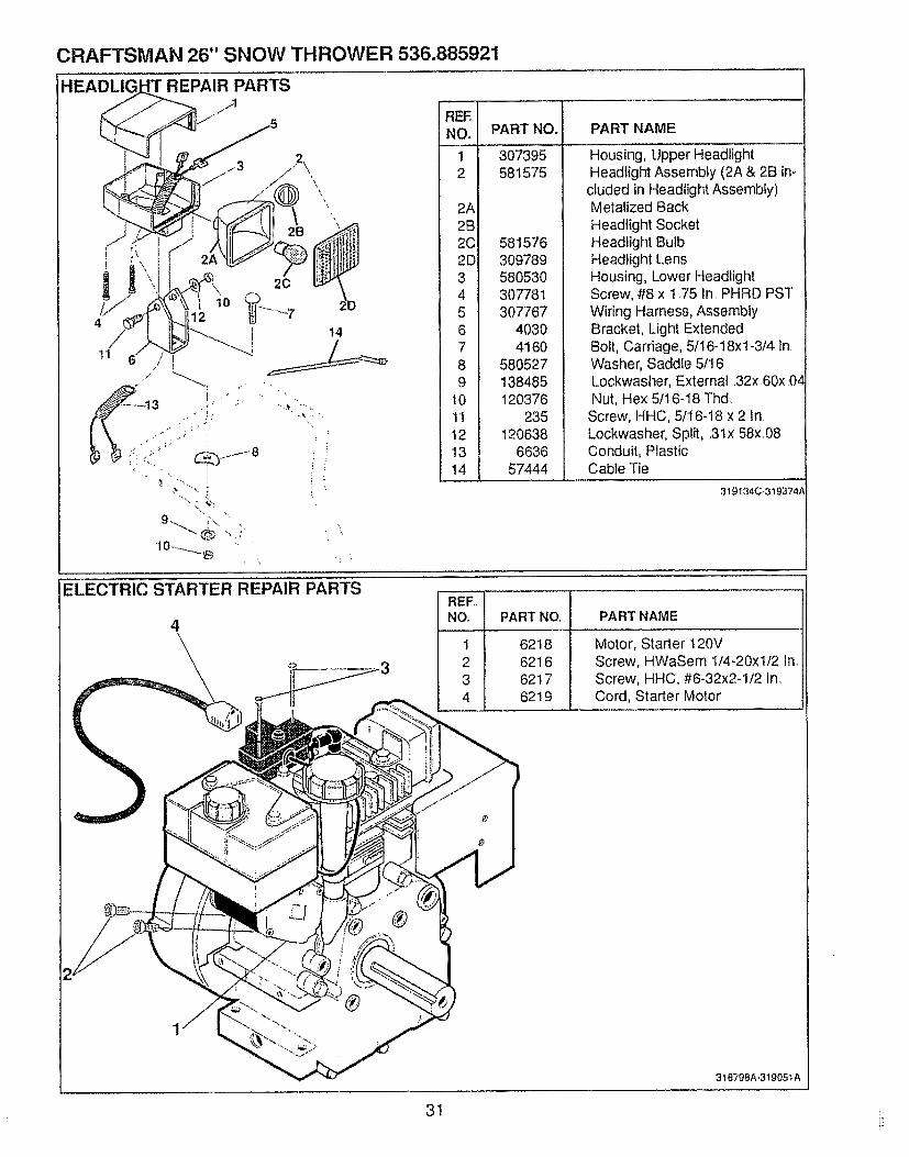
CRAFTSMAN 26" SNOW THROWER 536.885921
REPAIR PARTS/1
14
: I
"9 !2
2A2B202D3456789
101112•1314
PART NO.
307395581575
581576309789580530307781307767
40304160
580527138485120376
235120638
663657444
PART NAME
Housing, Upper HeadlightHeadlight Assembly (2A & 2B in-
cluded in Headlight Assembly)Metalized Back
Headlight SocketHeadlight BulbHeadlight LensHousing, Lower HeadlightScrew, #8 x 1.75 In. PHRD PSTWiring Harness, AssemblyBracket, Light ExtendedBolt, Carriage, 5f16-18xl-3/4 In.Washer, Saddle 5116Lockwasher, External 32x,60x 04Nut, Hex 5t16-I8 Thd
Screw, HHC, 5t16-18 x 2 In.Lockwasher, Split, .3lx .58x.08Conduit, PlasticCable Tie
319134C_319374A
ELECTRIC STARTER REPAIR PARTS
4PART NO.
6218621662176219
PART NAME
Motor, Starter 120VScrew, HWaSem I/4-20xtf2 In,Screw, HHC, #6-32x2-1/2 In,Cord, Starter Motor
318798A-319051A
31
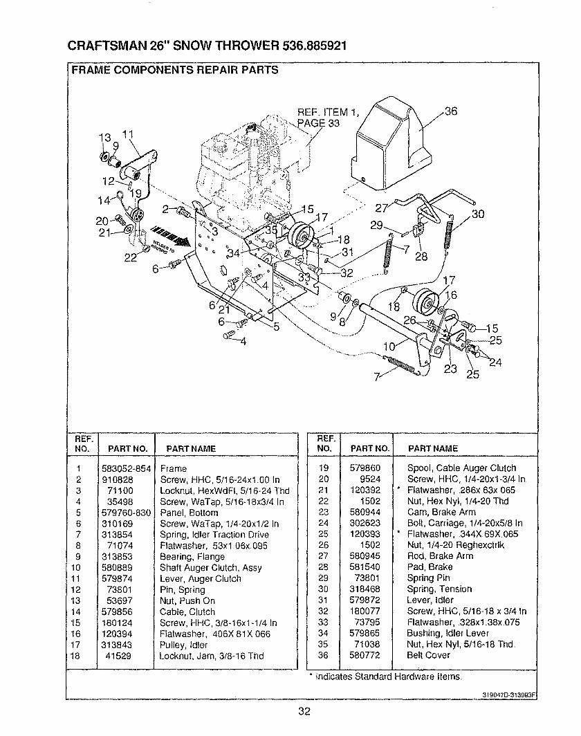
CRAFTSMAN 26" SNOW THROWER 536.885921
FRAME COMPONENTS REPAIR PARTS
13 11
6
REF,, ITEM 1,_E 33
]. # .,1
8
28
5
REF° !NO. I PART NO.
583052-854- ; 910828rj I
4 I
F
6 I
8 19 I
10 I11 |
12 I13 !14 I
15 116 I17 I18 I
7110035498
579760-830310169313854
710743138535808895798747380153697
57985618012412039431384341529
PART NAME
FrameScrew, HHC, 5/16-24xl 00 in.Locknut, HexWdFl, 5/16-24 ThdScrew, WaTap, 5/16-18x3/4 inPanel, BottomScrew, WaTap, 1/4-20xl/2 InSpring, Idler Traction DriveFtatwasher, 53xl 06x.095Bearing, FlangeShaft Auger Clutch, AssyLever, Auger ClutchPin, SpringNut, Push OnCable, ClutchScrew, HHC, 3/8-16x1-1/4 inFlatwasher, 406X 81X 066Pulley, IdlerLocknut, Jam, 3/8-16 Thd
" REF°NO,
!9202122232425262728293O313233343536
PART NO. PART NAME
5798609524
120392t502
580944302623120393
150258094558154073801
31846857987218007773795
57986571038
580772
Spool, Cable Auger ClutchScrew, HHC, 1/4-20xl-3/4 InFlatwasher, .286x ,63x, 065Nut, Hex Nyt, 1/4-20 Thd,Cam, Brake ArmBolt, Carriage, 1/4-20x5/8 in,.Flatwasher, 344X 69X065Nut, 1/4-20 ReghexctrlkRod, Brake ArmPad, BrakeSpring PinSpring, TensionLever, idlerScrew, HHC, 5/16-t8 x 3/4 InFlatwasher, .328x 1.38x .075Bushing, Idler LeverNut, Hex Nyl, 5/16-18 Thd.Belt Cover
Indicates Standard Hardware items
3190470-313993F
32
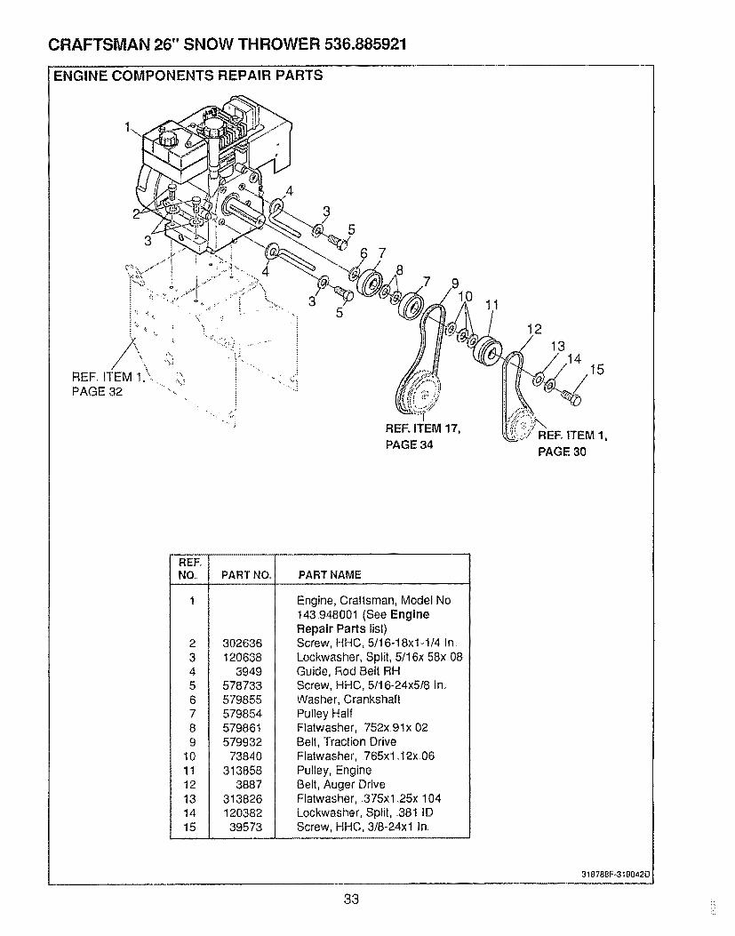
CRAFTSMAN 26" SNOW THROWER 536.885921
ENGINE COMPONENTS REPAIR PARTS
9
RER ITEM 17,PAGE 34
11
12/ 13
PAGE 30
1
23456789
10'1!12131415
PART NO_ PART NAME
302636120638
3949
Engine, Craftsman, Model No.!43.948001 (See EngineRepair Parts list)Screw, HHC, 5/16-18x1-1/4 In.Lockwasher, Split, 5/16x58x,08Guide, Rod Belt RH
578733579855579854579861579932
73840313858
388731382612038239573
Screw, HHC, 5/16-24x5/8 In,.Washer, CrankshaftPulley HalfFlatwasher, 752x 9 lx.02Belt, Traction DriveFlatwasher, 765x 1.12x, 06Pulley, EngineBelt, Auger DriveFlatwasher, 375x 1.25x. 104Lockwasher, Split, .381 IDScrew, HHC, 3/8-24xt In.
31878BF-3"_90420
33 !:;
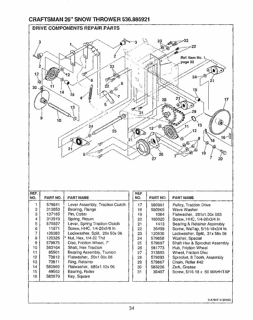
CRAFTSMAN 26" SNOW THROWER 536.885921
DRIVE COMPONENTS REPAIR PARTS
3
2
1\
10
415
28
Ref, Item No. 1,32
15
21
27
1
7 20
REF.NO.
123456789
10111213141516
PART NO. PART NAME
579941313853137185313919579937
11871120380120325579875583164855O17381273811
58096949562
580970
Lever Assembly, Traction ClutchBearing, FlangePin, Cotter'Spring, ReturnLever, Spring Traction ClutchScrew, HHC, 1/4-20x5/8 InLockwasher, Split, 26x 50xO6Nut, Hex, 1/4-20 ThdDisc, Friction Wheel, 7"Shaft, Hex TractionBearing Assembly, TrunionFlatwasher, .50xl 00x 06Ring, RetainerFlatwasher, 680xl.12x 06Bearing, RollerKey, Square
'NO. I
4"7 I
18 I19 i20 I2t 122 I23 l24 I25 I26 I27 I28 I29 I30 I31 I
PART NO. PART NAME
580961580965
1084180020
141335498
120638579858579897581773313883579893579867583206
35497
Pulley, Traction DriveWave WasherFlatwasher,. 281 x t .00x.O63Screw, HHC, t/4-20x3/4 In.Bearing & Retainer AssemblyScrew, WaTap, 5/16-18x3/4 inLockwasher, Split, .31 x58x.08Washer, SpecialShaft Hex & Sprocket AssemblyHub, Friction WheefWheel, Friction DiscSprocket, 8 Tooth, AssemblyChain, Roller #42Zerk, GreaseScrew, 5/16-18 x 50 WAHHTAP
318791 F-313995D
34
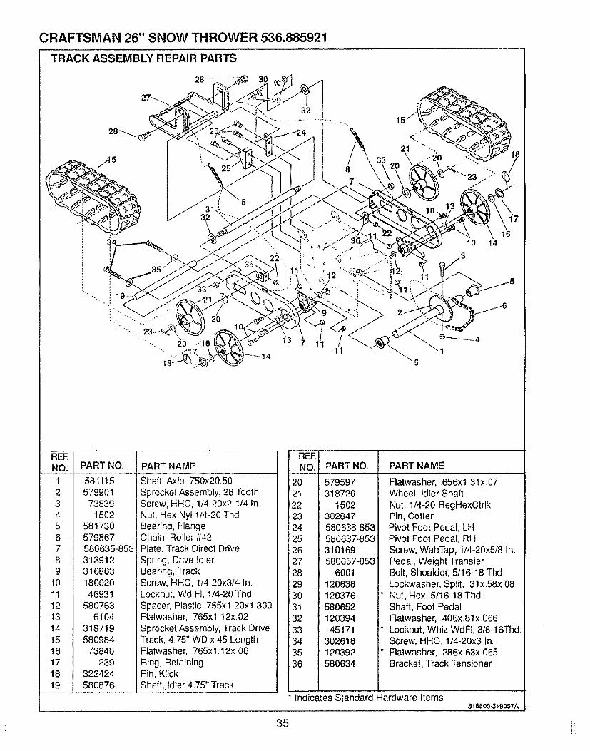
CRAFTSMAN 26" SNOW THROWER 536.885921
TRACK ASSEMBLY REPAIR PARTS
/15
20 "1
2O
22
32
10 14
3
REENO. PART NO.
1 5811152 5799013 738394 15025 5817306 5798677 580635_8538 3139129 316863
10 180020I1 4693112 58076313 610414 31871915 58098416 7384017 23918 32242419 580876
PART NAME
Shaft, Axie.750x20 50Sprocket Assembly, 28 ToothScrew, HHC, 1/4-20x2-1/4 InNut, Hex Nyl 1/4-20 ThdBearing, FlangeChain, Roller #42Plate, Track Direct DriveSpring, Drive IdlerBearing, TrackScrew, HHC, 1f4-20x3/4 ln,Locknut, Wd F], 1/4-20 ThdSpacer, Plastic 755xl 20x1300Ftatwasher,, 765xl 12x 02Sprocket Assembly, Track DriveTrack, 4 75" WD x 45 LengthFlatwasher, 765xl 12x 06Ring, RetainingPin, KlickShaft,, Idler 475" Track
REF.NO. PART NO.
20 57959721 31872022 150223 30284724 580638-85325 580637-85326 31016927 580657-85328 600129 12063830 12037631 58065232 12039433 4517134 30261835 12039236 580634
IPART NAME I
Flatwasher, 656xl 31x 07Wheel, Idler ShaftNut, 1/4-20 RegHexCtrlkPin, CotterPivot Foot Pedal, LHPivot Foot Pedal, RHScrew, WahTap, 1/4-20x5/8 In.Pedal, Weight TransferBolt, Shoulder, 5/16-18 Thd.Lockwasher, Split, 31x.58x.08
* Nut, Hex, 5/16-18Thd.Shaft, Foot PedalFlatwasher, 406x81x,066
* Locknut, Whiz WdFt, 3/8-16ThdScrew, HHC, 1/4-20x3 In
* Flatwasher, 286x63x 065Bracket, Track Tensioner
Indicates standard Hardware iierns318800-3t 9057A
35 i_
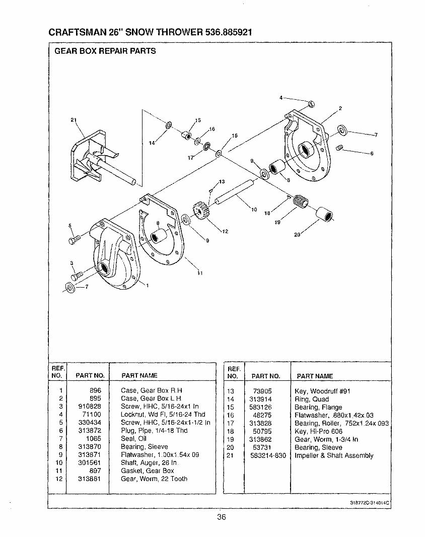
CRAFTSMAN 26" SNOW THROWER 536.885921
GEAR BOX REPAIR PARTS
21
\
19
20
REF.INO. i
.... .=,
213141
v i
61
8191
10I111
121
PART NO. PART NAME
896895
91082871100
330434313872
1065313870313871301561
897313861
Case, Gear Box RHCase, Gear Box L H.Screw, HHC, 5t16-24x! InLocknut, Wd FI, 5t16-24 ThdScrew, HHC, 5116-24x1-I/2 InPlug, Pipe, 114q8 ThdSeal, OilBearing, SleeveFlatwasher, 1.00xl .54x 09Shaft, Auger, 26 In.Gasket, Gear BoxGear, Worm, 22 Tooth
REF.NO. PART NO. PART NAME
131415161718192021
73905313914583126
48275313828
50795313862
53731583214-830
Key, Woodruff #91Ring, QuadBearing, FlangeFlatwasher, 880xl ,42x_.03Bearing, Roller, .752xt24x093Key, HFPro 606Gear, Worm, 1-3f4 In.Bearing, SleeveImpeller & Shaft Assembly
3t 8772C-3t 4014C
36
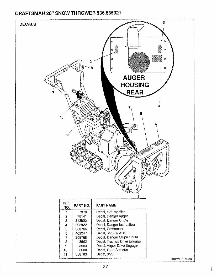
CRAFTSMAN 26" SNOW THROWER 536.885921
DECAt.S
AUGERHOUSING
REAR
7 4
510
11
REE
123456
i 789
i 1o
1
PART NO. PART NAME
737670141
313892302922308766402247308768
390239036300
308793
Decal, 12" ImpellerDecal, Danger AugerDecal, Danger ChuteDecal, Danger instructionDecal, CraftsmanDecal, 8126 SEARSDecal, Danger Stripe ChuteDecal, Traction Drive EngageDecal, Auger Drive EngageDecal, Gear SelectorDecal, 8/26
37
3t 8799F.,319347B
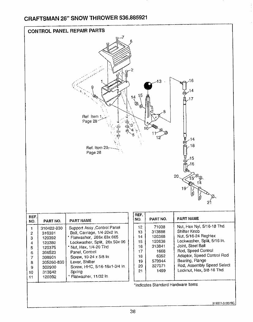
CRAFTSMAN 26" SNOW THROWER 536.885921
CONTROL PANEL REPAIR PARTS
6
,,_15
REFoNO,
!23456789
10tl
PART NO, PART NAME
310422-830310391120392120380120375306523308901305260-830302900313842120392
Support Assy.Control PanelBolt, Carriage, 1/4-20x2 In..
* Flatwasher,. 286x, 63x,065Lockwasher, Split, 26xS0x 06
* Nut, Hex, 1/4-20 ThdPanel, ControlScrew, 10-24 x 5/8 InLever, ShifterScrew, HHC, 5/16-18xl-3/4 In.Spring
* Flatwasher, 1t/32 in
REFoNO,
121314t5161718192021
PART NO,, PART NAME
71038313888120368120638313841
16686352
579944327071
1499
Nut, Hex Nyl, 5t16-18 Thd,Shifter KnobNut, 5/16-24 RegHexLockwasher, Split, 5/16 In,Joint, Steel BallRod, Speed ControlAdaptor, Speed Control RodBearing, FlangeRod, Assembly Speed SelectLocknut, Hex, 3/8-16 Thd.
*indicates Standard Hardware Items
38
319377-319378C
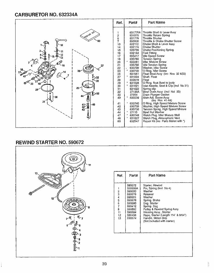
CARBURETOR NO. 632334A
i-30
12"t3
I
25
32
-4O
Ref.
1267t0141516171820212223252728293O3132334O
41424344474860
Part# Part Name
631776A631970631778650505632112632174630735632164650417630766632281630766630739630740631951631O2463201963102863102163102227136A27554632239
63O74063073963073827110630748631027632347
Throttle Shaft & Lever AssyThrottle Return SpringThrottle ShutterThrottle & Choke Shutter ScrewChoke Shaft & Lever Assy
: Choke ShutterChoke Positioning SpringFuel Fittingldte Speed ScrewTension Springldter Mixture Screwldle Tension SpringWasher, idler ScrewO Ring, Idler ScrewFloat 8owlAssy (Inc Nos 32 &33)Shaft. FtoatFloatO Ring, float Bowl to bodyInlet Needle, Seat & Clip (lncl No 31)Spring clipBowl DrainAssy (Incl No[ 33)Drain Plunger GasketMain Adj. Screw Assy
(hc Nos 41-44)O Ring, High Speed Mixture ScrewWasher, High Speed Mixture ScrewTension Sprng, High Speed MixtureBowl Nut WasherWelch Plug, ldter Mixture WellWelch Plug, Atmospheric VentRepair Kit (inc Parts Maket with °)
REWIND STARTER NO. 590672
11
..... i
Refo Part# Part Name
590672t 590599A2 5906003 5906794 5906015 5906786 59068O7 59O4128 59068211 59068412 59045613 590574
Starter, RewindPin, Spr}ng (Inc! No 4)WasherRetainerWasherSpring. BrakeDog. StarterSpring. DogPulley & Rewind Spring AssyHousing Assy, StarterRope, Starter (Length 114" & 9,'64")Handle, Mitten Grip(Not included with starter)
39 i:
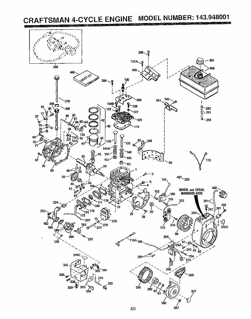
CRAFTSMAN 4-CYCLE ENGINE MODEL NUMBER: 143.948001
la\17
37\
/69
J223_. 173 25
26
182185
/286
4O
MODELandSERrALNUMBERSHERE
323
315/
90
J
J
287
370A
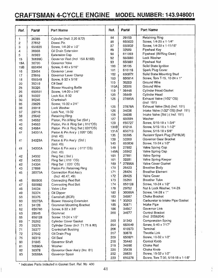
CRAFTSMAN 4-CYCLE ENGINE MODEL NUMBER: 143.948001_!!! !!! !_, ! .i,,i,,...... ........................................................
Ref,
!
23
4
51515A
15B
1617
!8
20
2526
2830
3536
3738
4O4O
4O
4t
4!
41
4242
4243
45
46
47
48
49
5060
6t62
6365
69
70
7t72
75
808t
82
83
Part# Part Name
35385
2765265O82O
309683O969
30699C3O700
65O494
3345429916
65054835319
35326
650561
3032236245
2982629918
2921629642
3455234553
3455434331A
34329A
34330A
3433234333
3433427888
35373A
650908
650882
34034
35374
3537533273A
3412665076O
28545650128
* 35262
35376
3537727642
35319
3184530590A
35378
30588A
Cylinder (IncL 2,20 &72)Dowel Pin
Screw, 1/4-20 x t/2 °.Oil Drain Extension
Extension CapGovernor Rod (lncl 15A &15B)Governor Yoke
Screw, 6-40 x 5/16"Governor Lever
Governor Lever ClampScrew, 8-32 x 5/t6"Oil Seat
Blower Housing BaffleScrew, t/4-20 x 5/8"
Lock Nut, 8-32Crankshaft
Screw, 10-32 x 2/4"Lock Washer
Lock Nut, 10-32
Retaining Ring
Piston, Pin &Ring Set (Std)Piston, Pin & Ring Set (010"OS)
Piston Pin & Ring Set (020"OS)
Piston & Pin Ass°y ( 020" OS)(tnct 43)
Piston & Pin Ass'y (Std)(Inc!. 43)
Piston & Pin ass'y ( 010" OS)(tncl 43)
Ring Set (Sld)Ring Set (.0t0" OS)
Ring Set ( 020- OS)Piston Pin Retaining RingConnection Rod Ass'y
(lncl 46,47, 49)Connecting Rod Bolt
Connecting Rod BoltValve Lifter
Oil DipperCamshaft (BCR)
Blower Housing Extension
Grommel Mounting BracketScrew, 8-32 x 3/8'GrommetScrew. 10-24 x t/2"
Cylinder Cover Gasket
Cylinder Cover (tncl 7t.75 & 80)
Crankshall BushingOil Drain PlugOil SealGovernor Shaft
Washer
Governor Gear Ass'y (Inc 8I)
Governor Spool
* indicates Pads lncfuded in Gasket Sert. Ref No 400
Ref.
84
86
8789
90
9293
100I0t
t 02103
t10
!10A
I19120
t 25
125
126126
127129
130B
13IA135
139
140
149149A
!50151
I69I70
I71
t72
t73I74
I78
182183
184185
186200
203
2O4
2O62O7
209
215
219
22O222
223
4t
Part# Part Name
29193
650833
65083232589
611093
650880650881
35135610118
650872650814
35253
35305
* 3644836449
27880A
27878A
3403634035
65O69165O727
6021A
65071335395
33369
650836
2788235862
2788132581
* 27896A28423
28424
2842535350
650128
2975230088A
34587
" 3326333871
3466734677
31342650549
610973
33878
650821
35440
3458635438
28820
650378
Retaining RingScrew, 1/4-20 x 1.1/4"
Screw, !/4-20 x I-1!/16"
Flywheel Key
Flywheel (WiRing Gear)Lock Washer
Flywheel Nut
Solid State IgnitionSpark Plug Cover
Solid State Mounting StudScrew, Torx T-15, !0-24 x 1"Ground WireGround Wire
Cylinder Head GasketCylinder HeadExhaust Valve (1/32" OS)(lncl 151)
Exhaust Valve (Std) (Incl. 151)Intake Valve (1/32" OS) (Incl 151)
Intake Valve (Std) ( Incl. 151)Washer
Screw, 5/16-!8 x 1-3/4"Screw, 5/16-18 x 1-1t2"
Screw, 5/16-18 x 5/8"
Resistor Spark Plug (RJ19LM)Governor Gear Bracket
Screw, 10°24 x 1/2"
Valve Spring CapValve Spring Cap
Valve SpringValve Spring KeeperValve Cover Gasket
Breather BodyBreather Efement
Valve Cover
Breather Tube
Screw, 10-24 x 1/2"Nut & Lock Washer, 1/4-28
Screw, 1/4-28 x t"Choke Bracket
Carburetor to Intake Pipe GasketIntake PipeGovernor Link
Control Bracket
(]nc! 203&204)
Compression SpringScrew, 5-40 x 7!17"Terminal
Throttle Link
Screw, 10-32 x t/2"
Control KnobChoke Rod
Choke Knob
Screw, t0-32 x t/2"Screw, Torx 7"-30, 5/16-18 x 1-1/8"
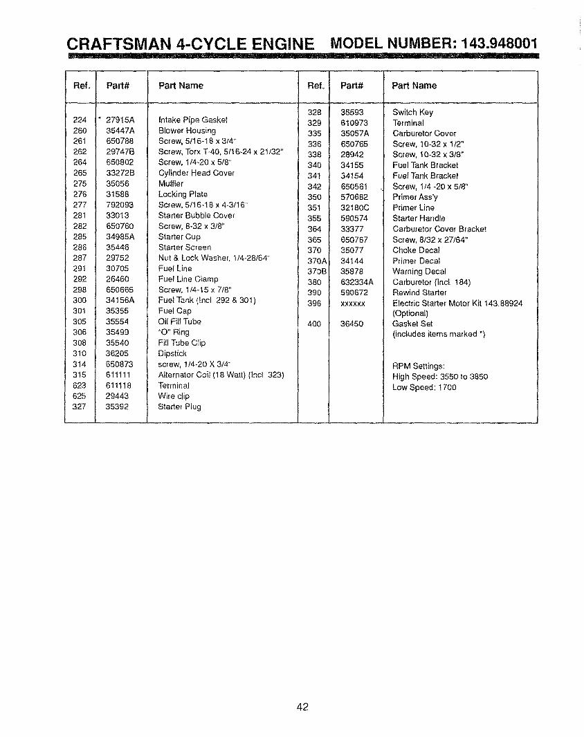
CRAFTSMAN 4-CYCLE ENGINE MODEL NUMBER: 143.948001i_ .... ..........i.._........... ......... ...__.i...............,. _ ....i_i__ ..................... IIIIII ............... r =', II '1 I
Ref,
224260
26t262264
265
275276
277
281282
285286
287291
292298
300301
3O5306
3O8
3t0314
3t5
623625327
Part#
27915A35447A
65078829747B650802
33272B
3505631588
792O93
3301365O76O
34985A35446
2975230705
2646O650665
34t56A35355
35554
354993554O
36205
650873611111
61111829443
35392
Part Name
Intake Pipe GasketBlower HousingScrew, 5/t 6-18 x 3/4++
Screw, Torx T-40, 5f16-24 x 21/32"Screw, 1/4+20 x 5/8"
Cylinder Head CoverMuffler
Locking PlateScrew, 5/16-18 x 4-3/16"Starter Bubble Cover
Screw, 8+32 x 3/8"
Starter CupStarter Screen
Nut & Lock Washer, 1/4+28/64"Fuel Line
Fuel Line ClampScrew, 1/4-t5 x 7/8"
Fuet Tank (tnct 292 & 301)
Fuel CapOil Fill Tube
"O" RingFill Tube Clip
Dipstickscrew, 1t4+20 X 3/4 "+
Alternator Coil (18 Watt) (lnc! 323)Terminal
Wire ctip
Starter Plug
L"O'Iti ......
328
329335
i 336338
340
, 34!i 342
350351355
L 364
i 365
370 ,370A370B!380 1
i 390396
400
Ii
i
Part#
35593
61O97335057A
65O76528942
3415534154
650561
57O68232180C
59057433377
65076735O77
34144
35878632334A590672
XXXXXX
36450
Part Name
Switch KeyTerminalCarburetor Cover
Screw, t0-32 x 1/2"Screw, 10+32 x 3/8"Fuel Tank BracketFuel Tar+k Bracket
Screw, 1/4 -20 x 5/8"
Primer Ass'yPrimer Line
Starter HandleCarburetor Cover Bracket
Screw, 8/32 x 27/64"Choke Deca!
Primer Decal
Warning DecalCarburetor (Incl t84)Rewind StarterElectric Starter Motor Kit 143, 88924
(Optional)Gasket Set
(includes items marked ")
RPM Settings:High Speed: 3550 to 3850
Low Speed: t700
42

[ NOTES
43
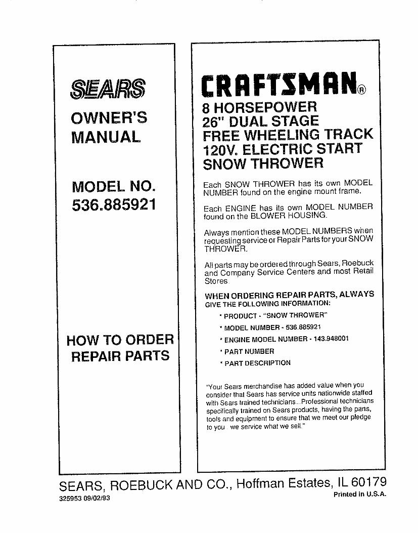
OWNER'SMANUAL
MODEL NO.536.885921
HOW TO ORDERREPAIR PARTS
CRRFTSMRN®8 HORSEPOWER26" DUAL STAGEFREE WHEELING TRACK120V= ELECTRIC STARTSNOW THROWER
Each SNOW THROWER has its own MODELNUMBER found on the engine mount frame.
Each ENGINE has its own MODEL NUMBERfound on the BLOWER HOUSING.
Always mention these MODEL NUMBERS whenrequesting service or Repair Parts for your SNOWTHROWER°
All parts may be ordered through Sears, Roebuckand Company Service Centers and most RetailStores.
WHEN ORDERING REPAIR PARTS, ALWAYSGIVE THE FOLLOWING INFORMATION:
* PRODUCT - "SNOW THROWER"
* MODEL NUMBER - 536,88592t
* ENGINE MODEL NUMBER - 143.948001
* PART NUMBER
* PART DESCRIPTION
"Your Sears merchandise has added value when youconsider that Sears has service units nationwide staffedwith Sears trained technicians.. Professional techniciansspecifically trained on Sears products, having the parts,tools =andequipment to ensure that we meet our pledgeto you we service what we sett."
SEARS, ROEBUCK AND CO.,325953 09102193
....... ............. . .:. ..................... .....
Hoffman Estates, IL 60179Printed in U.S.A,
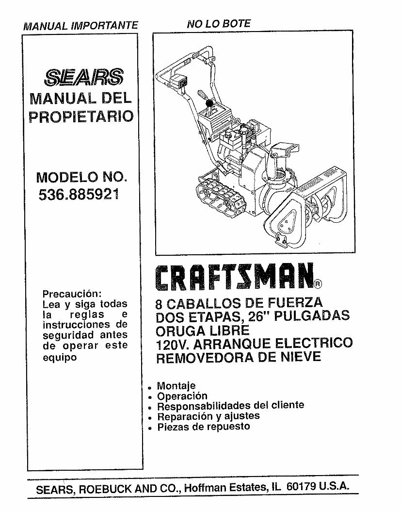
MANUAL IMPORTANTE NO LO BOTE
0UAL EL
ETARIO
MODELO NO.536.885921
Precaucion:Lea y siga todasia reglasinstrucciones deseguridad antesde operar esteequipo
PrSNRN 8 CABALLOS DE FUERZADOS ETAPAS, 26" PULGADASORUGA LIBRE120V. ARRANQUE ELECTRICOREMOVEDORA DE NIEVE
• Montajeo Operacion• Responsabilidades del cliente= Reparacion y ajusteso Piezas de repuesto
SEARS, ROEBUCK AND CO., Hoffman Estates, IL 60179 U.S.A.
REGLAS DE SEGURIDADPRECAUCION" SIEMPRE DESCONECTE ELALAMBRE DE LA BUJIAY COLOQUELO DONDE NO HAGA CONTACTO CON L BUJIA PARA AI_EVITAR UN ARRANQUE ACCIDENTAL AL MONTAR,TRANSPORTARo AJUSTAR O EFECTUAR REPARACIONES,
IMPORTANTEL©S ESTANDARES DE SUGURIDAD REQUIEREN LA PRESENCIA DE[_ OPERADOR EN LOSCONTROLES PARA MINIMIZAR EL RIESGO DE HERIDAS. SU REMOVERDORA DE NIEVEESTA EQUIPADA CON DICHOS CONTROLES. NO INTENTE PASAR POR ALTO LA FUNCIONDEL CONTROL DE PRESENC1A DEL OPERADOR BAJO NINGUNA CIRCUNSTANCIA.
CAPACITACION
t,, Lea el manual del operador cuidadosamente.Famlltaricese completamente con los controlesy el uso aproptado de la removedora de nieve_ Sepacbmo detener la removedora de nieve y desenganchar
los controles r_pidamente.
2. Nunca permita a ni#,os operar la removedora denieve y mantdngalos fuera del alcance de la mismamlentras se encuentra en operact6n.. Nunca permita
que adultos operen la removedora de nieve sininstruccibn apropiada. No Ileve pasajeros..
3.. Mantenga et drea libre de personas, especialmente
nirios peque_os y mascotaso
4. Tonga precaucibn a fin de evitar deslizamtentoso cafdas, especialmente al operar la removedorade nieve en retroceso.
PREPARACION
2_
3_
4_
Inspecclone completamente el brea donde se usara laremovedora de nieve y rot ire todas las esteras, trineos,tableros, alambres, y otros objetos extrarios..
Desenganche todos los embragues y cambie a neutroantes de arrancar el motor.
No opere la removedor a de nieve si nvest ir las prendasde invietno adecuadas para ambientes exteriores..
Vista calzado que mejore su estabilidad en superficieslisa&
Maneje et combustible con cuidado; es aitamenteinflamable.
(a) Use un contenedor para combustibleaprobado.
(b) Nunca retire la tapadera del tanque de corn*bustible o afiada combustible a un motor enmarcha o a un motor caliente.
(c) Llene el tanque para combustible al &ire libre,con culdado extremo. Nunca llene el tanqueen ambientes interiores.
(d) Coloque nuevamente la tapadera del tanquepara combustible de manera segura y |impieel combustible derramadoo
(e) Nunca almacene combustible o laremovedora de nieve con combustible en el
tanque dentro de un edificio donde losvapores pudiesen entrar en contacto conuna llama desprotegida o una chispa.
(f) Vertfique tas existencias de combustible an-tes de cada uso, permitiendo espacio paraexpansibn puesto que el calor del motor y!o
el sol pueden causar la expansi6n del com-bustible.
5. Use cables de extensl6n y receptdculos de la
manera especiflcada pot el fabrtcante para todastas removedoras de nieve con motores
accionados pot energla el_ctrica o motores dearranque eldctrico.
6. Ajuste la aitura de la removedora de nleve para pasarsobre superficies de grava o p[edra triturada..
7. Jambs tntente efectuar ningt)n ajuste mtentras el mo-tor se encuentra en marcha (excepto cuando etfabricante io recomtende asf espectficamente)_
8_
9_
Permita que el motor y la removedora de nieve seajusten alas temperaturas exteriotes antes decomenzar a retirar la nleve.
Siempre use galas de seguridad o protectores paralos ojos durante la operacf6n o mientras se efectt)a unajuste o reparacibn para proteger sus oJos de objetosextra_os que pudiesen ser lanzados pot la removedorade nlev&
OPERACION
1, No coloque las manos o los pies cerca o bajo piezasrotatlvas. Mant_ngase a distancia de la abertura para
descarga todo el tiempo..
2. Tonga precauct6n extrema al operar sobre o al cruzarcaminos, aceras, o calles de grava.. Mantengase alertaen caso de peltgros ocultos o tr_flcoo
3. Despues de golpear un objeto extrafio, pare el motor,retire el alambre de la bujla, desconecte el cable en
motores el_ctricos, tnspeccione completamente laremovedora de nieve a fin de encontrar cuatquler
da_o, y reparar dicho da_o antes de arrancar y operarla removedora de nieve nuevamente.
4. En el caso de que la removedora de nieve comience avibrar fuera de 1o normal, pare el motor y revise la
mbquina inmediatamente para encontrar ta causa.Generalmente, la vibracion es una advertencia de
problemaso
5. Pare el motor dondequtera que deje la posici6n de
operacl6n, antes de desobstruir el alojamiento dotbarreno/propulsor o gula de descarga, y cuando efecttJecualesquiera reparaciones, ajustes, o inspecciones_
6. At tlmpiar, reparar, o inspeccionar la maquina
aseg0rese de que el barrenotpropulsor y toda partemSvil se hayan detenido.. Desconecte el alambre de la
bujla y mant_ngalo alejado de la bujla para evitar unarranque accidental.
7o Tome todas las precauctones posibles al dejar la
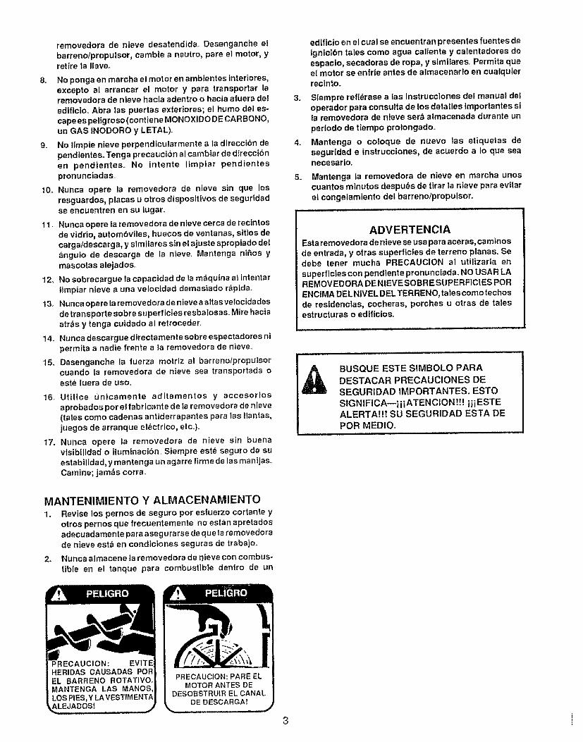
removedora de nieve desatendida.. Desenganche elbarreno/propulsor, cambie a neutro, pare el motor, yretire la llave.
8o No ponga en marcha el motor en ambtentes interiores,excepto al arrancar el motor y pare transportar laremovedora de nleve hacla adentro o hacla afuera del
edfficioo Abra |as puertas exteriores; el humo del es-cape es pellgroso (contiene MONOXIDO DE CAR BONO,un GAS INODORO y LETAL),.
9. No fimple nieve perpendicularmente ala dtreccibn dependientes° Tenga precauciSn al cambiar de direccI6nen pendlentes. No lntente limplar pendientespronunciadas.
t0. Nunca opere la removedora de nieve sin que losresguardos, placas u otros dispositivos de seguridadse encuentren en su lugar.
11, Nunca opere la removedora de nieve cerca de recintosde vidrio, autombviles, huecos de ventanas, s]tIos decarga/descarga, y slmilares sin el ajuste apropiado del_ngulo de descarga de la nieve.. Mantenga niRos y
mascotas alejados.,
12_ No sobrecargue |a capacidad de la maquina at intentartimptar nieve a una velocidad demasiado rapida.
13. Nunca opere taremovedora de nieve a altasveiocidadesde transporte sobre superficies resbalosas. Mire haciaatr_s y tenga cuidado al retroceder.
14. Nunca descargue dtrectamenle sobre espectadores nipermita a nadie frente ata removedora de nieve..
15o Desenganche la fuerza motriz al barreno/propulsorcuando la removedora de nieve sea transportada oeste fuera de uso_
"16. Uttllce flnicamente aditamentos y accesorlosaprobados por el fabrlcante de la removedora de nleve(tales como cadenas antiderrapantes para ias !tanlas,juegos de arranque el_ctrico, etco).
t7. Nunca opere la removedora de nieve sin buenavislbtltdad o ituminaci6n, Siempre este seguro de suestabilidad, y mantenga un agarre firme de las ma nijas._Camine; jam,_s corra_
edlflctoen el cue1se encuentran presentes fuentes de1gnicibn tales como agua caliente y calentadores deespaclo, secadoras de ropa, y similares. Permitaqueel motor se enfrle antes de atmacenar|o en cualqulerreclnto.
3. Siempre refidrase alas Instrucciones del manual deloperador para consulta de los detalles importantes sita removedora de nteve ser_ almacenada durante un
perlodo de tiempo proiongadoo
4. Mantenga o coloque de nuevo Jas etiquetas deseguridad e instrucciones, de acuerdo a 1o que seanecesarlo_
5. Mantenga la removedora de nieve en marcha unoscuantos minutos despu_s de tirar la nieve para evltarel congelamiento del barreno/propulsor.
ADVERTENCIAEsta removedora de nteve se usa para aceras, camfnosde entrada, y otras superficies de terreno planas. Sedebe tenet mucha PRECAUCION al utilizarla en
superficies con pendtente pronunctada_ NO USAR LAREMOVEDORA DENIEVE SOBRESUPERFIC1ES POR
ENCIMA DELNtVEL DEL TERRENO, taIes como techosde residencies, cocheras, porches u otras de talesestructuras o ediflcios.
BUSQUE ESTE SIMBOLO PARADESTACAR PRECAUCIONES DESEGURIDAD tMPORTANTES. ESTOSIGNIFICA_iiiATENCION !!! iiiESTEALERTA!!! SU SEGURIDAD ESTA DEPOR MEDIO_
MANTENIMIENTO Y ALMACENAMIENTO1. Revise los pernos de seguro pot esfuerzo cortante y
otros pernos que frecuentemente no estan apretadosadecuadamente para asegura rse de que la removedorade nieve est_ en condtciones seguras de trabajo.
2. Nunca almacene ta removedora de r_ieve con combus-
tible en el tanque pare combustible dentro de un
MOTOR ANTES DE
DE DESCARGA!
3 i
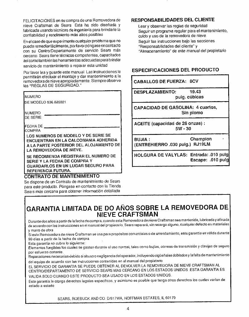
FELICJTAC_ONES en su com#ra de una Removedora denieve Craftsman de Sears. Esta ha sido diser_ada yfabficada usando tecnicas de ingenieda para brindafle taconfiab[_idad y rendimiento m_ls altos posibles
Enel caso de que expefimente cualquier problema que nopueda remediar f_,citmente, pot favor p6ngase en contactocon su Centro/Departamento de servicio Sears mascetcano, Sears tiene tecnicos competentes, capacitadosasicomo tambi6n las hertamientas adecuadas para brindatsetvicio de mantenimiento o reparar esta unfdad
Por favor iea y guarde este manual, Las instrucciones lepermitir_,n efectuar el montaje y dar mantenimiento a laremovedora de nieve apropiadame nte, Siempre observelas "REGLAS DE SEGUR]DAD,"
NUMERO
DE MODELO 536.885921
NUMERODE SERIE
FECHA DECOMPRA
LOS NUMEROS DE MODELO Y DE SERIE SE
ENCUENTRAN EN LA CALCOMANIA ADHERIDA
A LA PARTE POSTERIOR DEL ALOJAMIENTO DELA REMOVEDORA DE NIEVE.
SE RECOMIENDA REGISTRAR EL NUMERO DESERIE Y LA FECHA DE COMPRA Y
GUARDARLOS EN UN LUGAR SEGURO PARA
REFERENClA FUTURA.
CONTRATO DE MANTENIMIENTO
Se dispone de un Contrato de mantenimiento de Seats
para este producto.. P6ngase en contacto con la Tienda
Seats m,_s cercana para obtene_ informac[6n detallada
RESPONSABILIDADES DEL CLIENTE
Leer y observar ]as reglas de seguridadSeguir un programa regular para el mantenirniento,cuido y uso de la removedora de nieve
Seguir las instrucciones bajo 1as secciones
"Responsabilidades del cliente" y
"Almacenamiento" de este manual del propietario.
ESPEClFICAClONES DEL PRODUCTO
CABALLOS DE FUERZA: 8CV
Illll IlllllllI,L ...................
DESPLAZAMIENTO: 19.43
pulg. cObicas
CAPACIDAD DE GASOLINA: 4 cuartos,
Sin plomo
ACEITE (capacidad de 26 onzas) :5W - 30
BUJIA : Champion(ENTREHIERRO .030 pulg,) RJ19LM
HOLGURA DE VALYLAS: Entrada: .010 pu!!
Escape: .010 pulg i
GARANTIA LIMITADA DE DO ANOS SOBRE LA REMOVEDORA DENIEVE CRAFTSMAN
Durante dos a_os a partir de la fecha de compra, cuando esta Removedor a de nieve Craftsman sea mantenida, _ubficada y afinadade acuerdo con las instrucciones e n el manu al de l £ropietar o Sears reparar&, sin recargo alguno, cuatquier defecto en materiales
y mano de obraS{esta Removedora de nieve Craftsman se usa para propssi_os comerciales o de arrendamiento, esta garantia es v&]ida durante90 dias a partir de la fecha de compraEsta garantia no cubre !o siguiente:Elementos fungibles los cuaies se gastan dufante el uso normat, tates como buj[as, correas de transmisi6n y cfavijas de seguro
pot esfuerzo cortante.Reparaciones necesarias debido al abuso o negtigencia deIoperadoL inctuyendocig{JeP, ales doblados y lafatta de mantenimiento
de_equipo de acuerdo con ias }nsttucciones contenidas en el manua_ del ptopietarioEL SERViCIO DE GARANTIA SE PUEDE OBTENER AL DEVOLVER LA REMOVEDORA DE NIEVE CRAFTSMAN ALCENTRO/DEPARTAMENTO DE SERVICIO SEARS MAS CERCANO EN LOS ESTADOS UNIDOS ESTA GARANTIA ES
VALIDA SOLO CUANDO ESTE PRODUCTO SEA USADO EN LOS ESTADOS UNIDOS,
Esta garantia le otorga derechos tegates especificos, y asimismo es posib{e que tenga otros derechos los cuales varfan deestado a estado
SEARS, ROEBUCK AND CO. Di817WA, HOFFMAN ESTATES, IL 60179
4
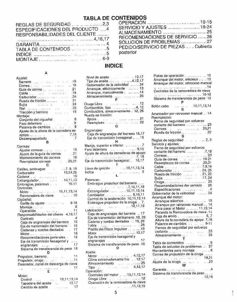
TABLA DE CONTENIDOSREGLAS DE SEGURIDAD .....................................2,3ESPECIFICACIONES DEL PRODUCTO ......4RESPONSABILIDADES DEL CLIENTE ....................................................................................4,16,17
GARANTIA ..................................................................4TABLA DE CONTENIDOS .....................................5INDtCE .........................................................................5MONTAJE ..............................................................6-9
OPE RACION ................................................. 10-15SERVICtO Y AJUSTES .............................. 18-24ALMACE NAM lENTO .........................................25RECOMENDACIQNES DE SERVICIO ........ 26SQLUCIQN DE PROBLEMAS ....................... 27PED1DO/SERVlCIO DE PIEZAS .............Cubierta
posterior
INDICE
Ajustet:Barreno ..................................... 19Correa ................................. 19Guta de correa ........................ 21Cable .............................................. ! 9Carburador ................................... 24Rueda de fricci6n ....................... 21Bujia .................................. 24Riel ................................ 23TracciSn y barreno .......... t9
Montaje:Conjunto det cigueRaf .......... 8Faro delantero ..................... 9Palanca de cambios ................. 9
Ajuste de la altura de la corredera deapoyo .................... 7, t 8Desempaquetado ....... 7
BCorreas:
Ajustar correas ....................... 19Ajuste de ta guia de correa .... 21Maintenimiento de correas .... 16Reemplazar correas ........ 20,21
CCables, embrague ............... 7.9, 19Carburador ............ 13,24,25Cadena ..................................... 16Extrangulador ....................... 10,1 t,!3Embrague, palancas ........ t0.t IControles:
Motor .................... 10,11,13,!4Removedora de nieve ............ 10
Cig0eRal:Varilla de ajuste ....................... 8.18Montaje ..................... 8OperaciSn ........................... 11
Responsabilidades del clienle 4,16,t7Contrato .......................... 4Caja de engranajes det barreno . 16Eje de transmisi6n del barreno 16Cadenas y ruedas dentadas .... 17Motor ................................... t 6Recomendaciones generates .... I6Eje de transmisi6n hexagonal y ....engranajes ......................... 17Sistema de transferencia de peso 16
DProputsor, barreno ................ 11Proputsor, oruga ........... 11Desviador, canal de descarga de nieve
....... , .................................. !!
EMotor:
Control .................... t0,11,13,t4Tapadera def aceite ........... t 2.17Cambio de aceite ............ 17
Nivet de aceite ..................... 12,17Tipo de aceite ...........................4,I2,t7Gobernador de la velocidad .............24
Arranque, el6ctricamente .................13Arranque, manualmente .......................14Almacenamiento ........................... 25
FOruga Libre ...................................... 12Combustible, tipo ...............................4, 12Combustible, almacenam}ento _..12, 25Rueda de lricci6n:
Ajuste ......................................... 21Reemplazo ............................... 22
G
Engranajes:Caja de engranaies dei barreno.16,17Eje de transmisi6n hexagonal ..........t6
H
Manija, superior e inferior ................. 7Faro deiantero .......................... 9,t0Ajuste de altura de correderas de apoyo.......................................... 7, 18Eje de transmisiSn hexagonal .... 16,17
ILlave de ignicion ............... t0,1 t,13,t4Indice .................................. 5
LPafancas:
Embrague propulsor de] barreno ..................................... 7,10,11,19Extrangulador .................. t0,11,13,14Cambiador ............................. 9,10,11Control de la aceleraciSn 10,11,13, t 4Embrague proputsor de la oruga .. 7,................................ 10,tt,19
Lubricacion:Caja de engranajes dot barreno .... 17Eje de transmisiOn del barreno_.16, 26Cadena y ruedas dentadas ......16, 26Tabla ............................................ 26Ptatilio del Disco lmputsor ...............16Motor ........................................ t 2,17Eje de transmisiSn hexagonal yengranajes .............................. 17Sistema de transferencia de peso 16
OAceite:
Motor ............................. 4,12,t7Clima extremadamente frio .... t2,17Almace namiento ........................... 25Tipo .................................. 4,12,17
Operaci6n:Controles del motor ......... I0,11 ,I3,14Oruga Libre ................................. 12Operaci6n de la removedora de nieve.......................... 11,12,I5
Pistas de operaci6n ...............................15Arranque del motor, el6ctrico ...........13Arranque del motor, retroceso manual....................................................................14Controles de la removedora de nieve................................................................10-12
Sistema de transferencia de peso t2P
BotSn cebo .................... t0,11,13,14R
Arrancador pot relroceso manual .....14Reemplazos:
Perno de seguridad por esfuerzocortante del barreno ............... 23Correas ............................. 20,21Rueda de fricciSn .................... 22
SReglas de seguridad .................... 2, 3Servicio y ajustes:
Perno de seguridad por esfuerzocoJlante det barreno .................... 7,18Correas ............................................ 23Guia de correa ......................... 19-21Reemplazos de correa .......... 20,21Cable ................................ 7,9,19Carburador ......................... 24, 25Rueda de fricciSn ................ 21,22Bujia .............................................17, 24Oruga ..........................................................23Recomendaciones der servicio .... 26Especificaciones ............................... 4
Gobernador de la velocidad ..............24Arranque del motor:
Arranque el_ctrico ........................ 13Arranque pot retroceso manual ... 14Para parar el Motor ...............11,13,14Parando la Removedora de nieve. 11
Caja de envio ..................................6, 7Altura de la corredera de apoyo 7,t8Patanca de cambios ................. 9-t !
Pernos de seguridad por esfuerzocortante ................................. 23Almacenamiento .................... 25
TTabla de contenidos ................................5Tabla de soluciSn de problemas ..... 27Herramientas para montaje ................. 6Correa de propulsiSn de la oruga ....................................................... 19,21
Ajuste de ta oruga .......................... 23W
Garantia ................................................. 4
Sistema de transierencia de peso ...................................................... 12,!8
5
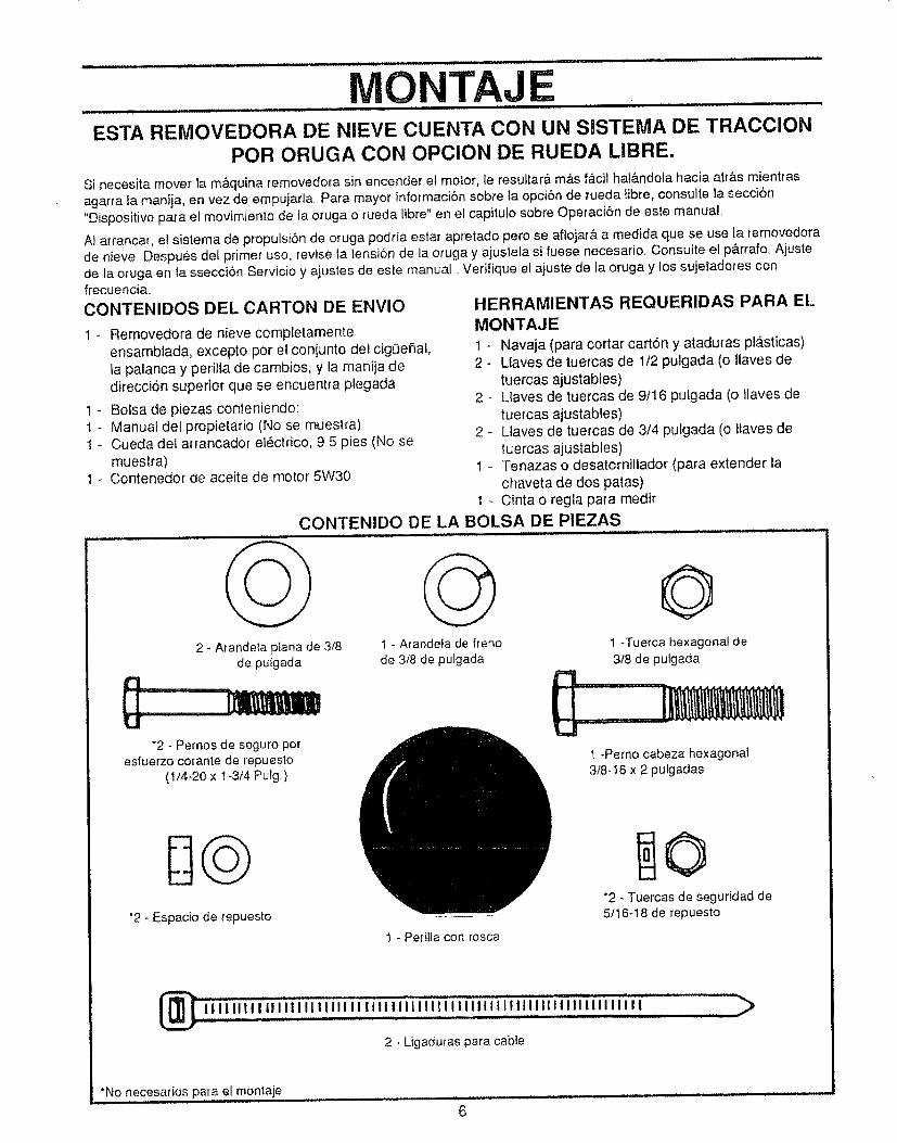
i,,i ii,,,,lll i nll,lnJ jl,, i,,, ill J ii i/ill.... ...........
MONTAJE__ IH, ,,I,L J ut ................. _ . .......
ESTA REMOVEDORA DE NIEVE CUENTA CON UN SISTEMA DE TRACCIONPOR ORUGA CON OPCION DE RUEDA LIBRE.
Si necesita mover la m&quina removedora sin encender el motor, le resuttar& m&s f_.cil hat&ndola hacia atr&s mientras
agarra la manija, en vez de empujarla. Para mayor informaciSn sobre la opci6n de rueda libre, consulte la secci6n
"Disposkivo para el movimiento de la oruga o rueda fibre" en et capitufo sobre Operaci6n de este manual
AI arrancar, el sistema de propulsiSn de oruga podria estar apretado pero se aflojar& a medida que se use la temovedora
de nieve. Despu,_s del primer uso, revise la tensi6n de la oruga y ajustela si fuese necesario. Consutte el p&rrafo, Ajustede ia oruga en la sseccion Servicio y ajustes de este manual. Verifique e] ajuste de la oruga y los sujetadores confrecuenci&
CONTENIDOS DEL CARTON DE ENVlO
1 - Removedora de nieve completamenteensambtada, excepto pot el conjunto de} cigOehal,la palanca y perilla de cambios, y la manija dedirecci6n superior- que se encuentra ptegada
1 - Bolsa de piezas conteniendo:1 - Manual del propietario (No se muestra)I - Cueda del arrancador electrico, 95 pies (No se
muestra)1 - Contenedor de aceite de motor 5W30
HERRAMIENTAS REQUERIDAS PARA EL,
MONTAJE
1 - Navaja (para cortar cation y ataduras pl_sticas)2 - Ltaves de tuercas de 1/2 pulgada (o Ilaves de
tuercas ajustables)
2 - Llaves de tuercas de 9/16 pulgada (o llaves de
tuercas ajustables)
2 - Llaves de tuercas de 3/4 pulgada (o tfaves de
tuercas ajustables)
1 _ Tenazas o desatomillador (para extender lachaveta de dos patas)
1 _ Cinta o regla para medir
CONTENIDO DE LA BOLSA DE PIEZAS
2 - Arandela p_ana de 3/8de putgada
"2 - Pernos de seguro potesiuerzo corante de repuesto
(1f4-20 x 1-3t4 Pulg )
*2 - Espacio de repuesto
t - Arande_a de fteno
de 3/8 de pulgada
O1 -Tuerca hexagonal de
318 de pulgada
t -Pemo cabeza hexagonal3/8-16 x 2 pulgadas
"2 - Tuercas de seguridad de5/16-18 de repuesto
1 - Perilla con rosca
2 - Ligaduras para cable
*No necesados para el montaje
6
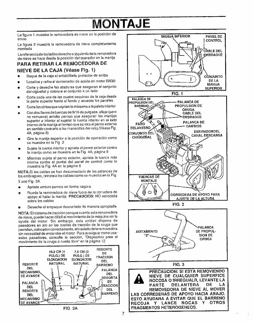
ONTAJLa figura I muestra la removedora de nieve en la posici6n deenvJo.
La figura 2 muestra la removedora de nieve completamentemontada
La referenciadelosladiosderecho e izquierdode la removedorade nieve se hace desde la posici6n del operador en la maniia
PARA RETIRAR LA REMOCEDORA DE
NIEVE DE LA CAJA (Vease Fig° 1)• Saque de la caja el entabliliado protector de arriba
m Localice y retire el contenedor de aceite de motor 5W30
• Corte y deseche las ataduras que aseguran el conjuntodel cig0eSal y cotoque el conjunto aun lade
e Corte cada una de las cuatro esquinas de la caja desdela parte superior hasta el rondo y acueste los paneles
e Corte las cintas que sujetan fa m_quina a la pateta inferior
• Con dos llaves de tuercas de 9/16 de pulgada, aftoje (poreno remueva) amobs pernos que aseguran las manijassuperior e inferior al sujetar la tuerca interior en ef tadointerne de la manija altiempo que se rota el perno externoen sentido contrario a las manecillas del rolei (V_ase Fig4A, pQgina 8)
• Gire la manija superior a la posici6n de operaci6n comese muestra en la Fig 2
® Su]ete ta tuerca interior y apriete el perno exterior contrala manija come se muestra en la Fig 4A, p_,.gina8
e Mientras sujeta el perno exterior, apriete ta tuerca mrsinterna contra el puntal del panel de contro! come tomuestra la Fig 4A en la pagina 8
NOTA:Si los cables se ban desconectado de las palancas delos embragues, reinstale los cables come se muestra en Ia Fig
3 and Fig 3A
o Apriete ambos pernos en lorma segura
o Ruede la removedora de nieve luera de la corredera de
apoyo al hafar Ia manija PRECAUClON: NO retrocedasobre los cabtes
o Deseche el empaque descartado de manera apropiada.
NOTA: El sistema de tracci6n con que cuenta esla removedorade nieve, puede hacer dilicit el movimiento de la m&quina sin faayuda gel motor Sin embargo, esta unidad dispone depasadores en are en las ruedas de tracci6n de la oruga queperm_en, colocados correclamente, et traslado de la removedorasin necesidad de encender el motor Para averiguar come usaresios pasadores, consulte ta secci6n, "Dispositivo parr elmovimiento de la oruga o rueda libre" en la p&gina 12
RESORTE10,2 CM (4 7,6 CM (3 DEPULG.) DE PULGo)DE TRACCtON
ELONGACION ELONGAC_ON DELRESORTE NATURAL NATURAL BARRENO
MECANISME__x._ __ ! ' PALANOADE AVANC DEL
PALANCA _"_t '_ RESORTADE
DEL lil RACCIONRESORTEIt' DELDEE ARRENO
MECANISMO_DE AVANCE....
FIG 3A
MANIJAiNFERiOR ...... PANEL"DECONTROL
DEL
FIG. 1
PALANCA DE
PROPULSION DEL
CONJUNTODE LA
MANIJASUPERIOR i
DEPROPULSION DE
ORUGACABLE DELEMBRAGUE
PALANCA DEOS
DESVIADORDELCANAL DESCARGA
CORREDERA DE APOYO PARAAJUSTE DE LA ALTURA
FIG, 2
ADITAMENTO DEPROPUL-SION DEORUGA
FIG, 3
PRECAUCION: SI ESTA REMOVIENDONIEVE DE CUALQUlER SUPERFiCEROCOSA O IRREGUALR, LEVANTE LAPARTE DELANTERA DE LAREMOVEDORA DE NIEVE AL MOVER
LAS CORREDERAS DE APOYO HACtA ABAJO.ESTO AYUDARA A EVITAR QUE EL BARRENORECOJA Y LANCE ROCAS Y OTROSFRAGMENTOS HETEROGENEOS..
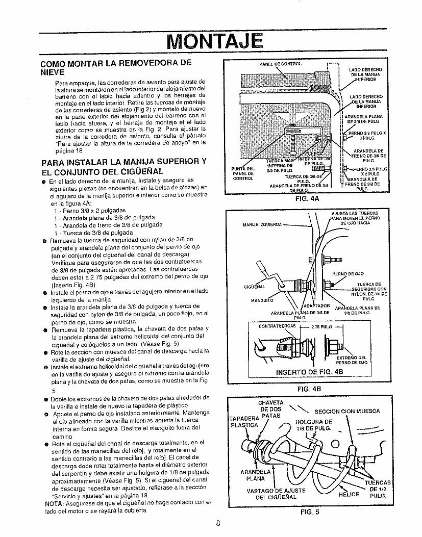
O EPANEL DE CONTROL
COMe MONTAR LA REMOVEDORA DENIEVE
Para empaque, las correderas de asiento para ajuste dela a(tura se montaron en el lade interior del a{o{amtento detbarreno con et labio hacia adentro y los herrajes demontaje en el iado interior, Retire {astuercas de montajede tas correderas de asiento (Fig 2) y monteto de nuevoen ta parte exterior det alojamiento del barreno con ellabio hacia afuera, y et herraje de montaje el el ladeexterior come se muestra en ta Fig 2 Pare ajustar laalutra de la corredera de asiento, consutte el p,_.rrale"Pare ajustar fa attura de ta corredera de apoyo" en lap_gina I8
PARA INSTALAR LA MANIJA SUPERIOR YEL CONJUNTO DEL ClGOEI_IAL• En el lade derecho de la manija, instate y asegure tas
siguientes piezas (se encuentran en ]a bolsa de piezas) enel agujero de ta manija superior e inferior come se muestraen ia figura 4A:
1 - Perno 3/8 x 2 pulgadas1 - Arandela p/ana de 3t8 de pu/gadat - Arandela de Irene de 3t8 de pulgada
1 - Tuerca de 3/8 de pulgadae Remueva la tuerca de seguridad con nylon de 3/8 de
pulgada y a{andeta piana del conjunto del perno de ojo(en e_conjunto del cigue,fai del canal de descarga)Verifique para asegurarse de que tas dos contratuercasde 3/8 de pulgada est_n apretadas Las contratuercasdeben estar a 2,75 pulgadas del extreme del perno de ojo(Inserto Fig, 4B)
• lnstaie el perno de ojo a traves del agujero inferior en el ladeizquierdo de la maniia
® Instate ta arandela plana de 3/8 de pufgada y tuerca deseguridad con nylon de 3/8 de pulgada, un poco floje, en elperno de ojo, come se muestra
e Remueva ta tapadera pl&stica, la chaveta de dos paras yla arandela plana del extreme helicoidal de! conjunto delcigiJeSal y col6quelos a un tado (V_ase Fig. 5)
• Rote la seccion con muesca de! canal de descarga hacia lavarilla de ajuste dei cig(ie_al,
e Instale el extreme helicoidal del cigOeSal atraves del agujeroen ta vatilla de ajuste y asegure el extreme con la arandelapiano y la chaveta de dos patas, come se muestra en la Fig
5
• Doble los extremes de la chaveta de dos paras alrededor de
la varilia e instale de nuevo la tapadera de pl&sticoe Apdele el perno de ojo instalado anteriormente Mantenga
el oje alineado con _avatilla mientras aprieta la tuercainterna en forma segura Deslice el manguito fuera de!camino
® Rote el cigOeRal del canal de descarga totatmente, en elsentido de ias manecitlas del reloj, y totatmente en elsentido contratio alas manecillas del retoj, Et canal dedescarga debe rotar totalmente hasta el diametro exteriordel serpentin y debe existi_' una holgura de 1/8 de pulgadaaproximadamente (V_ase Fig, 5) Si et cigLie_a! def canalde descarga necesita set ajustado, refietase a la secci6n
"Servicio y ajustes" en ta p&gina 18NOTA: AsegUrese de que el cig_eSal no haga contacto con ellade del motor o se rayar_, la cubierta
II_ADODERECHO
[, DE LA MANJJA
iUPERIOR
LADe DERECttO
LA MANiJA|NFERIOFI
il ARANDELA PLANA
DE 3/8 DE PULG
3t8 PULG X
E 318 DE
MANIJA IZQU
8
MAN_
PERNO DE OJO
TUERCA DESEGURIDAD CON
NYLON, DE3t8 DEPULG
ARANDELAPULG.
IDELAPLANA DEDE 318DEPULG
CONTRATUERCAS
2 75 P_
| EXTREMe DELPERNO DE OJO
INSERTO DE FIG. 4B
FIG, 4B
CHAVETA
DE DOS SECCION CION MUESCAT^DAn_A PATAS t....... L DE "HO GURAPLASTICA
1,'8_._._DEPULG_ . __
i ".,,-,/ _, , ./'_ TUERCASVASTAGODE AJUSTE '_ _ ,'_, ,..._._" DE 1/2
DELCIGOEglAL HELtCE PULG.
FIG. 5
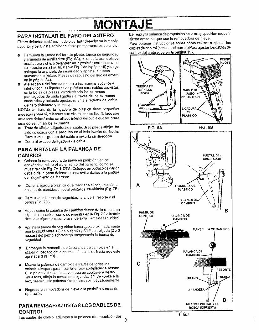
................... i/1//
MONTAJPARA INSTALAR EL FARO DELANTERO barrenoy lapatancadepropulsi6n de laoruga podrian requerir
El faro delantero esti_ montado en el lado derecho de ta manila ajuste antes de que use la removedora de nieve,superior y estfi instalado boca abajo para propdsitos de env_o Para obtener instrucciones sobre cdmo revisar o ajustar los
cables de control (consulte el p_rrafo Para ajustar los cables dedel embrac
@ Remueva la tuerca de! tornillo pivote, tuerca de seguridady arandela de ensilladura (Fig 6A), coloque la arandela deensilladura y el faro delantero en la posiciSncorrecta (comose muestra en la Fig..6B yen la Fig 2 de la p&gina 6) y tuegocoloque Ia arandela de seguridad y apriete la tuercanuevamente (V_ase Plazas de repuesto del faro detanteroen la p_gina 34).
® Ate et cable del faro delantero alas manijas superior einferior con las ligaduras de pl&stico para cables provistasen la bolsa de piezas introduciendo los extremospuntiagudos de cada ligadura a trav6s de tos extremoscuadrados y hafando ajustadamente alrededor del cabledel faro delantero y la manija
NOTA: Un lado de la ligadura de pl&stico tiene peque_,asmuescas sobre sl, mientras que el otto lado es liso El lado conmuescas debar& estar en ei lado interior dot bucle que se formacuando se juntan los extremos® Trate de aflojar la ligadura del cabie. Si se puede aflojar, ha
sido colocada con el lado liso en el lado interior def bucle
Remueva la ligadura det cable e invierta su direcci6n.® Corte el exceso de ligadura de cable
PARA INSTALAR LA PALANCA DE
CAMBIOS@ Colocar la removedora de nieve en posicion vertical
apoy&ndola sobre el alojamiento del barreno, como semuestra en la Fig. 7A. NOTA: Coloque un pedazo de cartondebajo de la parte delantera para evitar daSos a la pinturadel atojamiento dei barreno
e Corte Ia tigadura pl&stica qua mantiene el coniunto de lapafanca de cambios unido al puntaldot cambiador (Fig. 7B)
• Remueva la luerca de seguridad, arandela, resorte y elperno (Fig. 7D)..
e Reposicione la palanca de cambios dentro de ta ranura enel panel de control, como se muestra en la Fig 7C e instalede nuevo elperno, resorte, arandelaylatuerca deseguridad
Apt!ate la tuerca de seguridad hasta qua aproximadamenteuna !ongitudentre 1/8 de pu]gada y 3/16 de pulgada (2 5 3roscas) del perno sobresalga traspasando la tuerca deseguridad
®
® Enrosque la manecilla de la palanca de cambios en elextremo roscado de fa palanca de cambios hasta que est6apretada (Fig. 7D)..
Mueva ta palanca de cambios a traves de todas lasve!ocidadespara garantizartatensi6n apropiada delresorte.Si ta patanca de cambios se traba en cualquiera de lasmuescas, afloje Ia tuerca de seguddad 1t4 de vuelta a la
vez, hasta qua la palanca de cambios se mueva libremente
• Regrese la removedora de nleve a la posici6n normal deoperaciSn
9
PARA REVISAR/AJUSTAR LOS CABLES DE
CONTROt.Los cabies de control adjuntos a la palanca de propuisi6n dei
DEPLASTICO
FIG. 6A FIG. 6B
PLASTICO
PUNTALDEL
CAMBIADOR
A
PANELDE
CONTROL
PAl
CAM BIOS
PALANC A DECAMBIOS
B
MANECILLA DE CAMBtOS
/
CRESORTE
iJi DI/8 A 3/16 PULGADA DE
ROSCAEXPUESTA.... :: w
FIG,7
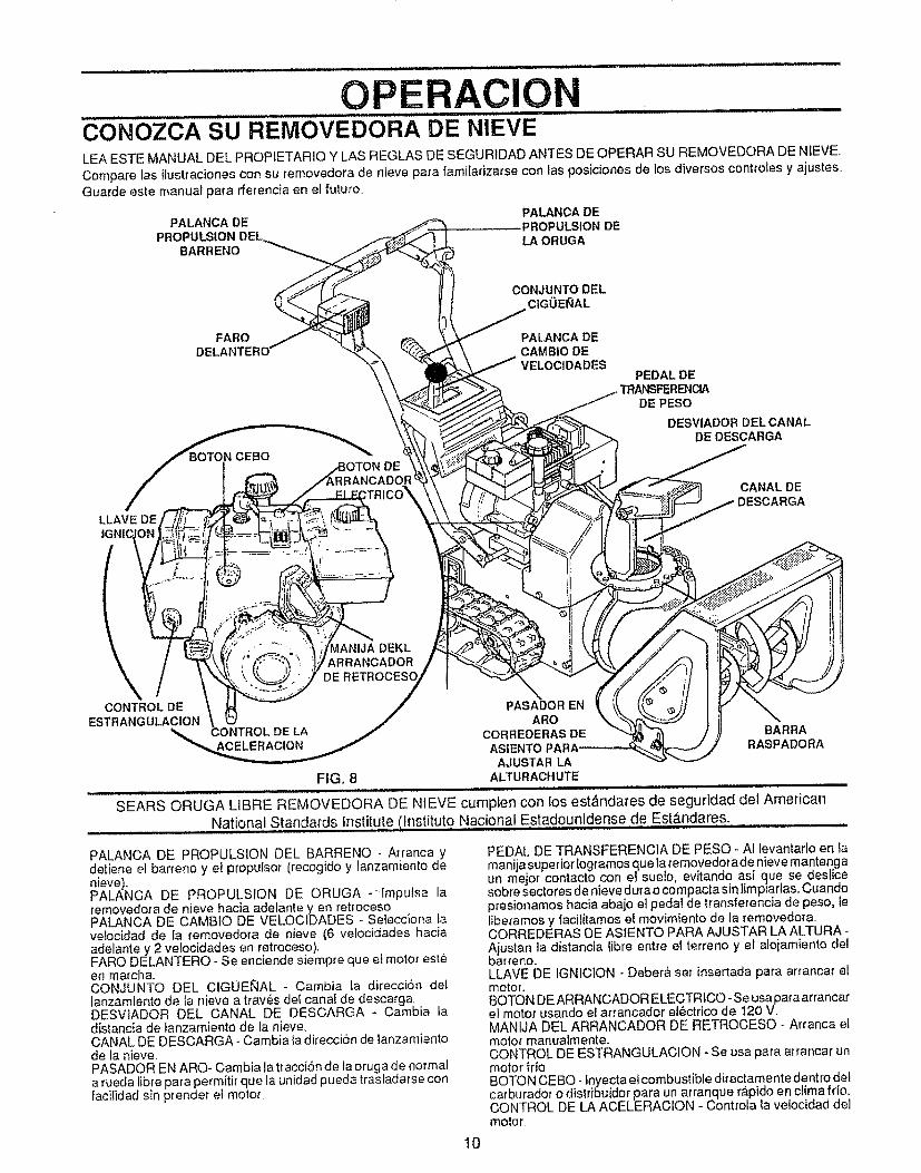
OP RAClO,i,, J ll,l,lllt
C0N"OZCA SU REMOVEDORA DE NIEVELEA ESTE MANUAL DEL PROPIETARIO Y LAS REGLAS DE SEGURIDAD ANTES DE OPERAR SU REMOVEDORA DE NIEVE,
Compare las ilustraciones con su removedora de nieve para famitarizarse con ias posiciones de los diversos controles y ajustes..Guarde este manual para rferencia en el futuro
PALANCA DE PALANCA DEPROPULSION DE
BARRENO LAORUGA
CONJUNTO DELC|GOE_AL
FARO PALANCA DEDELANTERO CAMBIO DE
VELOC|DADES
CEBO
PEDAL DETRN_FERENClA
DE PESO
DESVIADOR DELCANALDE DESCARGA
LLAVE DE
CANAL DEDESCARGA
\CONTROL DE
ESTRANGULACIONCONTROL DELA
_ANIJA DEKLARRANCADOR
DE
PASADOR ENARO
CORREDERAS DEASIENTO
AJUSTAR LAFIG. 8 ALTURACHUTE
SEARS ORUGA LIBRE REMOVEDORA DE NtEVE cumpien con los est&ndares de seguridad del American
National Standards Institute Ilnstituto Nacional Estadounidense de Est&ndares,
BARRARASPADORA
PALANCA DE PROPULSION DEL BARRENO - Arranca ydetiene el barreno y el propulsor (recogido y lanzamiento denieve).PALANCA DE PROPULSION DE ORUGA -_Impulsa laremovedora de nieve hacia adelante yen retrocesoPALANCA DE CAMBIO DE VELOCIDADES - Selecciona taveiocJdad de la removedora de nieve (6 velocJdades haciaadelante y 2 velocidades en retroceso),FARO DELANTERO - Se enciende siempre que el motor esteen marcha+CONJUNTO DEL CIGOENAL - Cambia la direcciSn dellanzamiento de ta nieve a trav_,s de_ canal de descargaDESViADOR DEL CANAL DE DESCARGA - Cambia tadistancia de tanzamiento de la nieve,CANAL DE DESCARGA - Cambia ta direccion de lanzamientode ta nieve,PASADOR EN ARO- Cambia la tracci6n de la oruga de normala rueda libre para permitir que ta unidad pueda trasladarse conlacilidad sin prender el motor
PEDAL DE TRANSFERENCIA DE PESO- AI levantarlo en tamanijasuperior [ogramos que la removedorade nieve mantengaun mejor contacto con el suefo, evitando asi que se deslicesobre sectores de nieve dura o compacta sin limpiarlas,, Cuandopresionamos hacia abaio el pedal de _ransferencia de peso, leliberamos y facilitamos el movimiento de la removedora,CORREDERAS DE ASIENTO PARA AJUSTAR LA ALTURAAjustan la distancia libre entre el terreno y el alojamiento delbarreno.LLAVE DE IGNICION - Deber& ser insertada para arrancar elmotor.BOTON DEARRANCADOR ELECTRICO -Se usapara arrancarel motor usando el arrancador e16ctrico de 120 V,MANfJA DEL ARRANCADOR DE RETROCESO - Arranca elmotor manualmente.CONTROL DE ESTRANGULACION - Se usa para arrancar unmotor frlo,BOTON CEBO- fnyecta el combustible directamente dentro delcarburador o distribuidor para un arranque r,_pido en clima frio,,CONTROL DE LA ACELERACION - Controta la velocidad delmotor,
10
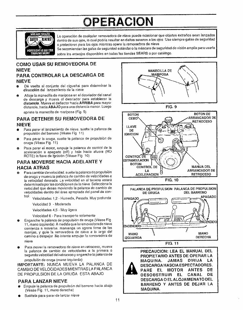
OPERACIONLa operaci6n de cualquier removedora de nieve puede ocasionar que objetos extraSos sean lanzadosdentro de sus ojos, {ocuat podda resultar en daSos severos a los ojos Use siempre galas de seguridado protectores para los ojos mientras opere la removedora de nieveSe recomiendan las galas de seguridad est&ndar o la m&scara de seguridad de visi6n amplia para usarla
sobre Ios anteojos disponibles en todas Jastiendas SEARS o pot cat&logo.
COMO USAR SU REMOVEDORA DE
NIEVEPARA CONTROLAR LA DESCARGA DENIEVEe D_ vuelta al conjunto del cigbe_al para determinar la
dtreccibn del lanzamiento de Ia nieve
0 Afioje la manecilfa de mariposa en el desviador del canalde descarga y mueva et desviador para establecer iadistancia.. Mueva el deflector hac_a ARRIBA para mayordistancia, hacia ABAJO para una distancia menor. Luego
apriete la manedlla de mariposa (Fig 9)
PARA DETENER SU REMOVEDORA DE
NIEVE0 Para parar el Ianzamiento de nieve_ suelte la palanca de
proputs_n del barreno (V6ase Fig 11)
0 Para parar la oruga, suelte ta palanca de propulsbn deoruga (V_ase Fig tt)
® Para parar el motor, empuje ta palanca de control de laaceleraci6n a apagado (off) y hale hacia afuera (NOROTE) la !lave de ignici6n (V6ase F{g 10)
PARA MOVERSE HAClA ADELANTE Y
HAClA ATRAS• Para cambiar de velocidad, sueIte la palanca de propulsiSn
de oruga y mueva la patanca de cambio de vefocidades ala velocidad deseada La velocidad en el terreno estar&determinada por tascondiciones de Ia nieve Seleccione lavelocidad que desea moviendo ia palanca de cambio devefocidades dentro del &rea apropiada del panel de con-trol.
Velocidades 1,2 - H0meda, Pesada, Muy profunda
VeIocidad 3 - Moderada
Velocidades 4,5 - Muy Iigera
O
Velocidad 6 - Para transporte solamen_eEnganche Ia palanca de propulsion de oruga (Vease Figt t, mano izquierda) A medida que ta removedora de nievecomienza a moverse, mantenga un agarre firme de fasmanijas, y guie la removedora de qieve a Io largo deIcamino a despeiar No intente empuiar Ia removedora de
nieve
• Para mover la removedora de nieve en retroceso, muevala palanca de cambio de velocidades a la primera osegunda velocidad del retroceso y enganche la palanca de
propulsiSn de oruga (mano izquierda)IMPORTANTE: NUNCA MUEVA LA PALANCA DE
CAMBIO DE VELOCIDADES MtENTRAS LA PALANCA
DE PROPULSION DE LA ORUGA ESTA ABAJO
PARA LANZAR NIEVE• Empuje la palanca de propulsi6n del barreno hacia abajo
(V_ase Fig. 1i, mano derecha)
• SueIteta para parar de lanzar nieve
MANECILLA DE,_.__.._MMA_POSA \ \\
FIG. 9
BOTON
LLAVEDE
IGNIOION
BOTON DECADOR DE
RETROCESO
ESTRAt,_ULAClONBOTON
CONTROL DE MANIJA DELLA ARRANCADOR DE
ACELERACION RETROCESO
FIG. 10
PALANCA DE PROPULSION PALANCA DE PROPULSIONDE ORUGA DEL BARRENO
APAGADO ._APAGADO
NC-ENDIDCENCEND1DO.............................. "_
MANO|ZQUIER DA DERECHA
FIG_ 11|| lllHll _,l
PRECAUClON: LEA EL MANUAL DELPROPIETARIO ANTES DE OPERAR LA
MAQUINAo JAMAS DIRIJA LA
DESCARGA HASClA ESPECTADORES.
PARE EL MOTOR ANTES DE
DESOBSTRUlR EL CANAL DE
DESCARGA O EL ALOJAMIENATO DEL
BARRENO Y ANTES DE DEJAR LA
MAQUINA.
1! r
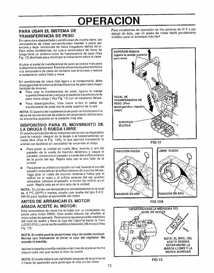
................................ ../ ................
PARA USAR EL SISTEMA DETRANSFERENCIA DE PESOEn nieve dura compactada o condiciones de mucha nieve, tasremovedoras de nieve convencionales tienden a pasar potencima y dejat mont{cutos de nieve irregulares detr_fis de si.Para estas condiciones, su nueva removedora de nieve deoruga tiene un sistema unico de transferencia de peso (VeaFig 12) diseSado para minimizar ei rodamiento sobre ta nieve.
........................,.,...............,........ ............OPErtAC,ONPara condiciones de operaci6n de frio extremo de 0° F y pordebajo de _sta, use un aceite de motor 0w30 parciaimentesint_tico para un arranque mAs fAciL
AI pisar el pedal de transierencia de peso se coloca m_s pesoa] alojamiento delbarreno Estatransferenciade peso mantienea (a removedora de nieve en contacto con e{ terreno y reduceeI rodamiento sobre hielo y nieve
En condiciones de nieve m&s ligera o al t_ansportarla, debedesenganchar el sistema de transferencia de peso para mayorfacitidad de timoneo® Para usaf {a transferencia de peso, agarre ia manija
superior firmemente y empuje eIpedal de transferencia depeso hacia abaio ( Vea Fig 12) con et metatatso del pie
® Para desenganchar, hate hacia arriba el pedal detransferencia de peso con la parte superior de su pie
NOTA: El sistema de transferencia de peso no funciona_&silaaituta de las correderas de asiento del alojamiento de! barrenose encuentra ajustada en [a posici6n mas alto
DISPOSITIVO PARA EL MOVIMIENTO DELA ORUGA O RUEDA I.IBREE1sistema de traccibn de su m_quina cuenla con un dispositivopara la tracci6n integrat de la oruga o e! funcionamiento enrueda tibre (Vea la Fig. 12A), to que permite transporlar launidad con t'aci[idad sin necesidad de encender el motor
Para poner la unidad en rueda fibre: tevante et aro delpasador de la rueda de tracciSn defantera y saque elpasador; introduzca el pasador a trav_s del orificio exter node la punta det eje Repita esto con eJ otto iado de Iaunidad
o
e Para poner la unidad en tracciSn normal: levante el aro delpasador colocado en el orificio externo de la punta def eje;haga girar la rueda de traccion delantera hasta que elorificio en el cubo y el orificio extemo del eje quedenalineados; cotoque el pasador a trav_s del ofificio en elcubo. Repita esto en el otto lado de ta unidad
NOTA: En zonas con temperaturas consistentemente al nivelde -6 70C (20°F) o menos, puede usar aceite det tipo S AE5W-30 para facitita_ el encendido del motor
ANTES DE ARRANCAR EL MOTORANADA ACEITE AL MOTOR:Esta removedora de nieve rue enviada con un cont_enedor deaceite para motor 5W30, Este aceite deber& ser aSadido atmotor antes d e operar]o. Remueva la tapadera/varilfa medidoradel nivel de aceite y llene la caja del ci9_eSal hasta la lineaLLENO (FULL) en la varilla medidora de! aceite (26 onzas) (VeaFig 13)
NOTA: El motor podrla ya contener algo de aceite residual•Revise con frecuencla al |lenar la caja det cigLiehal. Noexceda ta medtda.
Apriete Ia tapadera!vatilla medidora del nivel de aceite en formasegura cada vez que revise et nivel de aceite
NOTA: El aceite deber_ set cambiado despues de ias pfimeras2 horas de operaci6n para prolongar la vida utit del motor
......... ,,, ,,,illill
SUPERIOR MANIJA(agarre la manljapara usar)
=EDAL DETRANSFERENCIA DEPESO (Para
desenganchar, tmpulsoN,,,abaio)
SUPERIORMUESCA
FIG.12
TRACCI(_N RUEDA
"t
FIG, 12A
LIBRE RUEDA
TAPADERANARILLA MEDIDORA DEL ......._ ....
NIVELDEACEL_
12
NOTA: EL NIVEL DELACEITE DEBERAESTAR ENTRE LA
MARCA LLENOI Y LAMARCA AGREGAR
: ll,,., i u i i ..i
FIG,13
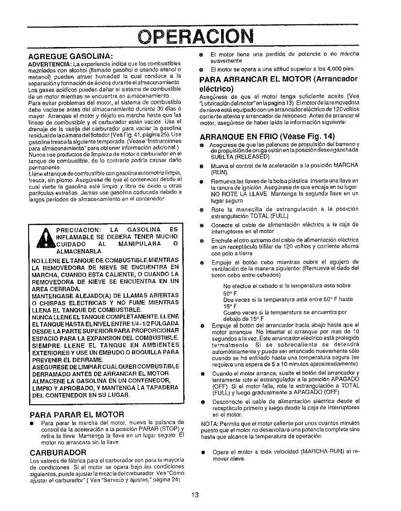
OPERACIONAGREGUE GASOLINA:ADVERTENCIA: La experiencia indica que los combustiblesmezclados con alcohol (llamado gasohol o usando etanol ometanol) pueden atraer humedad ta cual conduce a laseparaci6n y formaci6n de _,cidos d urante e! almacenamientoLos gases acidicas pueden daSar el sistema de combustiblede un motor mientras se encuentra en almacenamiento.Para evitar problemas del motor, el sistema de combustibledebe vaciarse antes de! almacenamiento durante 30 dias omayor Arranque el motor y dejelo en marcha hasta que laslineas de combustible y el carburador est6n vacios Use eldrenaje de la vasija del carburador para vaciar la gasolinaresiduatde lac&maradelflotador (Vea Fig. 41, p&gina25)..Usegasolina fresca la siguiente temporada. (V6ase"instruccianespara almacenamiento" para obtener informaci6n adicional )Nunca use productos de limpieza de motor o carburador en eltanque de combustible, de Io contrario podria causar daSopermanenteLlene eltanque de combustible con gasolina automo|rizfimpfa,tresca, sin plomo. AsegL_rese de que et contenedor desde elcuaJ vierte {a gasolina est6 limpio y libre de 6xido u olraspartfculas extraSas Jamas use gasolina caducada debido alargos periodos de almacenamiento en el contenedor
PRECUACION: LA GASOLINA ESINFLAMABLE SE DEBERA TENER MUCHOCUIDADO AL MANIPULARA OALMACENARLA_
NO LLEN E EL TANQUE DE COMBUSTIBLE M1ENTRASLA REMOVEDORA DE NIEVE SE ENCUENTRA EN
MARCHA, CUANDO ESTA CALIENTE, O CUANDO LAREMOVEDORA DE NIEVE SE ENCUENTRA EN UNAREA CERRADA,
MANTENGASE ALEJADO(A) DE LLAMAS ABIERTASO CHISPAS ELECTRICAS Y NO FUME MIENTRASLLENA EL TANQUE DE COMBUSTIBLE°NUNCA LLENE ELTANQUE COMPLETAMENTE. LLENEEL TANQUE HASTA EL N1VEL ENTRE 1/4 - 1/2 PULGADADESDE LA PARTE SUPERIOR PARA PROPORCIONARESPACIO PARA LA EXPANSION DEL COMBUSTIBLE°S1EMPRE LLENE EL TANQUE EN AMBIENTESEXTERtORES Y USE UN EMBUDO O BOQUILLA PARA
PREVENIR EL DERRAME.ASEGURESE DE LIMPIA R CUALQUIER COMBUSTIBLEDERRAMADO ANTES DE ARRANCAR EL MOTOR,._LMACENE LA GASOLINA EN UN CONTENEDOR,
LIMPIO Y APROBADO, Y MANTENGA 'LA TAPADERA[:)EL CONTENEDOR EN SU LUGAR_
PARA PARAR EL MOTOR• Para parar la marcha del motor, mueva la palanca de
control de la aceteraci6n a la posici6n PARAR (STOP) yretire la lfave Mantenga la llave en un lugar seguro E!motor no arrancara sin la Ilave
CARBURADORLos valores de f&brica para el carburador son para la mayoriade condiciones Si et motor se opera bajo tas condicionessiguientes, puede ajustar la mezcla delcarburador Vea"C6moajustar ei carburador" ( Vea "Servicio y ajustes," p_gina 24)
e E1 motor tiene una perdida de potencia o no marchasuavemente.
@ El motor se opera a una altitud superior a los 4,000 pies..
PARA ARRANCAR EL MOTOR (Arrancador
electrico)Aseg,3rese de que et motor tenga suliciente aceite (Vea"Lubricaci6n del motor"en lapagina 13) E1motorde la removedorade nieve est& equipado con un arrancador el_,ctrico de I20 voltioscorriente alterna y arrancador de retroceso. Antes de arrancar elmotor, aseg_rese de haber leido la informaci6n siguiente:
ARRANQUE EN FRIO (Vease Fig. 14)@ Asegurese de que las patancas de propuisi6n del barreno y
de propulsi6n deorugaest&n en laposici6ndesenganchadaSUELTA (RELEASED).
® Mueva el control de la aceleraci6n a la posici6n MARCHA(RUN).,
• Remueva las llaves de ta bolsa pl&stica, tnserte una llave enla ranura de ignici6n, AsegLirese de que encaja en su lugar,NO ROTE LA LLAVE Mantenga la segunda llave en unlugar seguro
® Rote la maneciila de estrangulaci6n a la posici6nestrangulaci6n TOTAL (FULL)
e Conecte el cable de alimentaci6n el6ctrica a la caja deinterruptores en el motor.
e Enchufe et otro extremo del cable de alimentacion e!_clricaen un recept&cuio trifilar de 120 vottios y corriente aiternacon polo a tierra
e Empuje ei bot6n cebo mientras cubre el agujero deventifaci6n de la manera siguiente: (Remueva el dedo delbot6n cebo entre cebados)
No etectue el cebado si la temperatura esta sobre50° F.Dos veces si Ia temperatura est& entre 50° F hastat5 ° F,.Cuatro veces si la temperatura se encuentra pordebajo de 15° F
e Empuje el bot6n del arrancador hacia abajo hasta que elmotor arranque No intentar el arranque pot mas de 10segundos a la vez. Este arrancador e!6ctrico est& protegidotermalmente Si se sobrecalienta se detendr&autom&ticamente y puede ser arrancado nuevamente s61ocuando se ha enfriado hasta una temperatura segura (serequiere una espera de 5 a t0 minutos aproximadamente)
® Cuando el motor arranca, suelte el bot6n del arrancador ylentamente rote el estrangulador a la posici6n APAGADO(OFF), Si el motor falfa, rote la estrangulaci6n a TOTAL(FULL) y luego gradualmente a APAGADO (OFF)
® Desconecte el cable de alimentaci6n el6ctrica desde elrecept&culo primero y luego desde la caja de interruptoresen el motor.
NOTA: Permita que el motor caliente por unos cuantos minutospuesto que el motor no desarrollar& una potencia completa sinohasta que alcance ta temperatura de operaci6n
• Opere el motor a toda velocidad (MARCHA-RLIN) al re-mover nieve.
13
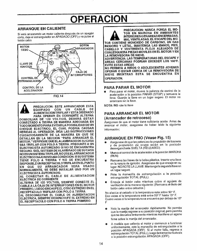
O RACION.......................................... : ............. i iiilUll iiii ..... iii,ii.u,i ,,
ARRANQUE _N CALIENTE .........................................
Si est_ ar_'ancando un motor caliente despues de un apag6ncorto, deje el estrangulador en APAGADO (OFF) y no pulse etbot6n cebo
BOTON 80TON
LLAVE DE
CAJA DEINTERRUPTORES
CONTROL DE LAACELERACION
FIG,14
A PRECAUCION: ESTE ARRANCADOR ES3"A._ EQUIPADO CON UN CABLE DEa==_,m= AL|MENTACION TRJFILAR Y ESTA DISENADO
PARA OPERAR EN CORRIENTE ALTERNADOMtCILIAR DE 120 VOLTtOS. DEBERA ESTAR
j CONECTADO A TIERRA DE MANERA ADECUADA ENTODO MOMENTO PARA EVITAR LA POSIBILIDAD DE UNCHOQUE ELECTRICO, EL CUAL PODRIA CAUSARHERIDAS AL OPERADOR. SIGA LAS INSTRUCCIONESCUIDADOSAMENTE DE LA MANERA EN QUE SEDETALLAN EN LA SECCION "PARA ARRANCAR ELMOTOR." VERIFIQUEQUE ELALAMBRADO DE SU CASASEA TRIFILAR CON POLO A TIERRA. PREGUNTE A UNELECTRICISTA AUTORIZADO SI NO SE ENCNUENTRASEGUROo S! EL SISTEMA DE ALAMBRADO DE SU CASANO ESUN SISTEMA TRIFILAR,NO USE ELAR RANCADORELECTRICO BAJO NINGUNA CONDICION. SI SU SISTEMATIENE POLO A TIERRA Y NO SE ENCUENTRADISPONIBLE UN RECEPTACULOTRIFILAR EN EL PUNTOEN QUE SU ARRANCADOR SERA USADONORMALMENTE, SE DEBE INSTALAR UNO POR UNELECTRICISTA AUTORIZADO.AL CONECTAR EL CABLE DE ALIMENTACIONELECTRICA DE CORRIENTEALTERNA DE 120 VOLTIOS, SIEMPRE CONECTE ELCABLE A LA CAJA DE INTERRUPTORES EN EL MOI"OR
PRIMERO, LUEGO ENCHUFE EL OTRO EXTREMO EN ELRECEPTACULO TRIFILAR CON POLO A TIERRAoAL DESCONECTAR EL CABLE DE ALIMENTACIONELECTRICA, SIEMPRE DESENCHUFE EL EXTREMO ENEL RECEPTACULO CON POLO A TIERRA PRIMERO.
PRECAUCION: NUNCA PONGA EL MO-
A TOR EN MARCHA EN AMBIENTESINTERIORES O EN AREAS ENCERRADAS,MAL VENTILADAS. EL ESCAPE DEL MO-
TOR CONTIENE MONOXlDO DE CARBONO, UN GASINODORO Y LETAL MANTENGA LAS MANOS, PIES,CABELLO Y VESTIMENTA FLOJA ALEJADOS DECUALESQUIERA PIEZAS MOVILES EN EL MOTOR Y ENLA REMOVEDORA DE NIEVE.ADVERTENCIA: LAS TEMPERATURAS DEL ESCAPE YAREAS CERCANAS PODRIAN EXCEDER LOS 150°F.EVITE ESTAS AREAS,NO PERMITA A NII_OS O ADOLESCENTES JOVENESOPERAR O ESTAR CERCA DE LA REMOVEDORA DENIEVE MIENTRAS ESTA SE ENCUENTRA EN
OPERACION.
PARA PARAR EL MOI"OR• Para parar et motor, mueva la palanca de control de la
aceterac/6n a la posic{6n PARAR (STOP) y remueva latlave. Guarde la Ilave en un lugar seguro. Ei motor noarrancara sin ta tlave.
NOTA: NO rote la liave
PARA ARRANCAR EL MOTOR
(Arrancador de retroceso)Asegurese de que el motor tiene suticiente aceite. Antes dearrancar el motor, asegurese de haber re,do la siguiente
informaci6n:
ARRANQUE EN FRIO (Vease Fig. 15)® Asegurese de que tas pa_ancas de proputsibn del batreno
y de propulsi6n de o_uga est&n en la posiciondesenganchada SUELTA (RELEASED).
e Mueva elcontrol de la aceleraci6n a fa posici6n MARCHA(RUN)
e Remueva las tlaves de ta botsa pi&stica. Inserte una Iiaveen la ranura de igniciSn. AsegOrese de que encaja en su{ugar NO ROTE LA LLAVE _Mantenga la segunda Ilave enun lugar seguro.
• Rote ta manecilla de estrangulaci6n a la posiciSnestranguLaciSn TOTAL (FULL).
® Empuje el bot6n cebo mientras cubre el agujero deventilaci6n de ta manera siguien!.e: (Remueva el dedo delbot6n cebo entre cebados.)
No efectue e! cebado si la temperatura esta sobre 50° F.Dos veces si la temperatura esl_ entre 50 ° F basra I5 ° F.Cuatro veces si la temperatura se encuentra pot debajo de 150F
O
@
Hate la manija del arrancador rApidamente. No permitaque la manija regrese a su posici6n original, pero permitaque se devuelva {entarnente mientras mantJene un agarre
firme sobre la manJia del arrancador..
A medida que caiienta et motor y comienza a funcionaruniformemente, rote la maneciila de estrangulaci6n a laposici6n APAGADA (OFF) Si el motor falla, regrese aestrangulaci6n TOTAL (FULL), Luego lentamente mu6valaa la posici6n estrangulaci6n APAGADA (OFF)..
14
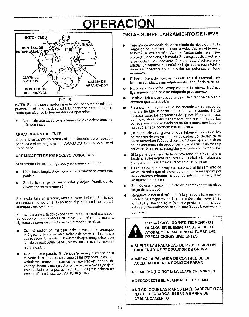
OPERACION L i,,i, nmL : ................ :
BOTON PISTAS SOBRE LANZAMIENTO DE NIEVE
FtG,,15
NOTA: Permita que el motor caliente pot unos cuantos minutospuesto que el motor no desarrollar,& una potencia compJeta sinohasta que aicance la temperatura de operacibn
e Opere el motor a o aproximadamente a la velocidad m&ximaal lanzar nieve
ARRANQUE EN CALIENTE
Si est& arrancando un motor caliente despu6s de un apagon
corto, deje el estranguiador en APAGADO (OFF) y no putse elbot6n ceboo
ARRANCADOR DE RETROCESO CONGELADO
Si et arrancador esta congelado y no arranca el motor:
e Hale tanta iongitud de cuerda de! arrancador como seaposible
o Suelte la manija de{ arrancador y d_jeia enro{larse denuevo contra el arrancador
@
Si el motor falia en arrancar, repita el procedimiento S[ intentoscontinuados no liberan el arrancador, siga el procedimiento paraarranque e{6ctrico en fr[o.
Para ayudar a evitar la posibilidad de congelamiento del arrancadorde retroceso y los contro_es de! molor, proceda de la manerasiguiente despu_,s de cada trabajo de remocion de nieve
®
o
Con el motor en march& hale ta cuerda de arranqueen_rgicamente con un alargamienlo de brazo continuo tres ocuatro veces. E1halado de fa cuerda dea[ranque producir& unsonido de repiqueteo fuede Esto no causa da5o ni al motor ni
al arrancador,.
Con el motor parado, limpie toga _anieve y humedad de _acubierla de{ carburador en e{area de las pafancas de controlAsimismo, mueva el control de aceteraci6n, control deestrangulaciSn, y manija del arrancador varias veces y deje elestrangulador en la posiciSn TOTAL (FULL) y Ia palanca deaceleraciSn en la posici6n MARCHA (RUN)
Para mayor eficiencia de lanzamiento de nieve durante laremoci6n de ta m]sma, aiuste la velocidad en el terreno,NUNCA la aceleraci6n.. Avance lentamente en nieve
profunda, congetada, o htJmeda..Si laoruga desliza, reduzcala velocidad hacia adetante.. El motor esta diseRado parabdndar un rendimiento m&ximo bajo aceleraci6n total ydebe ser operado en este valor de potencia en todomomento.
e El lanzamiento de nieve es m&s eficiente si la remoci_n dela misma se efectLJainmediatam ente despu_s de su caida
• Para una remoci6n completa de ta nieve, trasJapeligeramente cada camino adoptado previamente
O La nieve deber[a ser descargada en la direccion del vientosiempre que sea posible
• Para uso normal posicione Eas correderas de apoyo demanera tal que ta barra raspadora se encuentre 1/8 depulgada sobre las correderas de apoyo. Para supediciesde nieve dura extremadamente compacta, ajuste lascorrederas de apoyo hacia arriba de manera que [a barraraspadora haga contacto cor_ e_terreno..
• En superficies de grava o roca triturada, posicione lascorrederas de apoyo a 1-1/4 pulgadas por debajo de _abarra raspadora (V6ase e[ p&rrafo "C6mo ajustar la atturade las correderas de apoyo" en la p&gina 19) Las rocas ygrava no deber_n set recogidas y lanzadas pot la maquina
o Si _aparte delantera de la removedora de nieve tiene Iatendenciade elevarse reduzca la velocidad sobre elterreno
y enganche ef sistema de transferencia de peso..
e Despu_s de que se haya completado el lanzamiento denieve, permita que el motor se encuentre en reposo porunos cuantos minutos, Io cual derretir#, la nieve y hietoacumulado del motor
O
O
Efectue tma limpieza completa de ia removedora de nievetuego de cada uso
Remueva la acumulaciSn de hie!o y nieve y todo materialextrafio heterog6neo de la removedora de nieve en sutotalidad, y lave con agua (si fuese posible) para removertoda sal u otras substancias quimicas Sequela removedora
de nieve
PRECAUCION: NO INTENTE REMOVER
CUALQUIER ELEMENTO QUE RESULTEATORADO EN BARRENO SI TOMAR LASPRECAUCIONES S1GUIENTES:
• SUELTE LAS PALANCAS DE PROPULSION DELBARRENO Y DE PROPULSION DE ORUGA,,
• MUEVA LA PALANCA DE CONTROL DE LAACELERAC|ON A LA POSICION PARAR.
• REMUEVA (NO ROTE) LA LLAVE DE |GNICION
• DESCONECTE EL ALAMBRE DE LA BUJtA.
® NO COLOQUE LAS MANOS EN EL BARRENO O CANAL DE DESCARGA, USE UNA BARRA DEAPALANCAMIENTO.
15
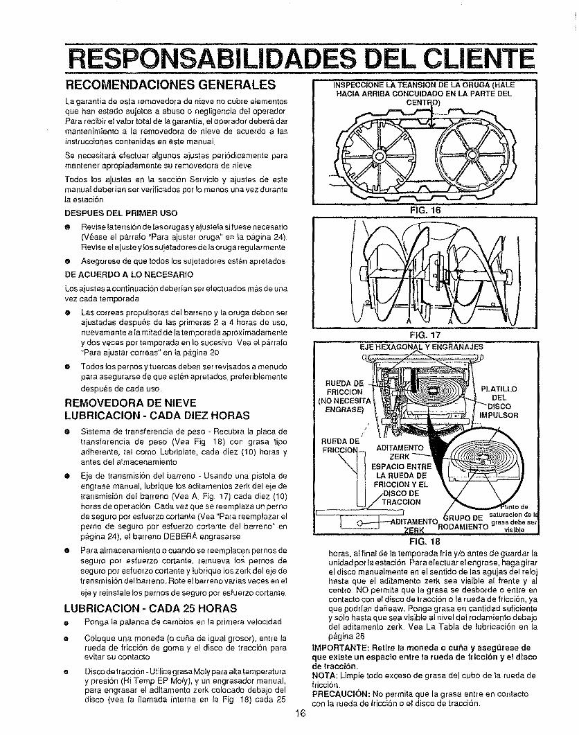
EL CLI........................ ,, ,,,,w, i,, i i ulu,,,, lliH 11 J i llllllllll ii i,, i,llll . l lll n,i ,,
RECOMENDACIONES GENERALES INSPECCIONE LA TEANSIO_NDE LA ORUGA (HALE
La garantia de esta _emovedora de nieve no cubre eIementosque han estado sujetos a abuse o negligencia del operadorPara recibir el valor total de la garantia, el operador deber& darmantenimiento a la removedora de nieve de acuerdo alasinstrucciones contenidas en este manual,
Se necesitar& efectuar algunos ajustes peri6dicamente paramantener ap_opiadamente su removedora de nieve
Todos los ajustes en la secci6n Servicio y ajustes de estemanuat deberian set vedficados per Io menos una vez durantela estaci6n
DESPUES DEL PRIMER USO FIG. 16
e Revise latensi6n detasorugas y aj'bstefa sifuese necesario(V6ase el p&rra|o "Pare ajustar oruga" en la pagina 24)Revise e! aiuste y los sujetadores de la oruga regularmente
e Asegurese de que todes los sujetadores est&n apretados
DE ACUERDO A LO NECESARIO
Los ajustes a contin uacion deberian set efectuados m&sde unavez cada tempotada
e Las correas propulsoras det barreno y la oruga deben setajustadas despu6s de tas primeras 2 a 4 hotas de use,nuevamente a la mitad de latemporada aproximadamentey dos veces per temporada en lo sucesivo Vea el p&rrafo
"Para ajustar correas" en la p&gina 20
e Todos los pemosy tuercas deben set revisados a menudopara asegurarse de que est_n apretados preferibiemente
despu6s de cada use
REMOVEDORA DE NIEVE
LUBRICAClON - CADA DIEZ HORAS
O Sistema de transferencia de peso - Recubra la place detransferencia de peso (Vea Fig 18) con grasa ripeadherente, tal come Lubriplate, cada diez (10) horas yantes del atrnacenamiento
e Eje de ttansmisi6n del barreno - Usando una pistola deengrase manual, lubrique los aditamentos zerk de! eje detransmisiOn del ba[reno (Vea A, Fig t7) cada diez (10)horas de operaci6n Cada vez que se reemplaza un pemode seguro per esfuerzo cortante (Vea "Para reemplazar elpemo de seguro per esfuerzo cortante dei barreno'" enp&gina 24), el batreno DEBERA engrasa_se
e Para ahnacenamiento o cuando se reemplacen pernos deseguro per esfuerzo cortante, remueva lo.s pernos deseguro per esfuerzo cortante y iubrique los zerk del eje detransmisi6n del barreno. Rote ef barreno varias veces en et
eje y reinstale los pernos de seguro per esfuerzo cortante.
LUBRtCAClON - CADA 25 HORAS
e Ponga la palanca de cambios en la primera velocidad
Coloque una moneda (o cuba de iguat grosor), entre larueda de fficci6n de goma y el disco de tracci6n peraevitar su contacto
Disco detraccion-Utilice grasa Mofy papa attatemperaturay presi6n (Hi Temp EP Moly), y un engrasador manual,papa engrasar el aditamento zerk cotocado debajo deldisco (vea la ilamada interne en la Fig 18) cada 25
FIG. 17
EJE HEXAGONAL Y ENGRANAJES
RUEDA DEFRICCION i
(NO NECESITAENGRASE)
/
RUEDA DEFRICC|O_ ADITAMENTO
ZERK
ESPAClO ENTRELA RUEDA DE
FRICCION Y EL
PLAT1LLODELllSCO
IMPULSOR
16
FIG, 18
horas, al final de la temporada fria y/o antes de guardar launidad per la estaci6n, Para efectuar el engrase, haga gitarel disco manuaimente en et sentido de las agujas del relojhasta que el aditamento zerk sea visible al frente y alcentre NO permita que la grasa se desborde o entre encontacto con e! disco de tracci6n o la rueda de fricci6n, yaque poddan daReawo Ponga grasa en cantidad suficientey s61ohaste que sea visible al nivel del todamiento debaiodel aditamento zerk, Vea La Tabla de iubricaci6n en lap&gina 26
IMPORTANTE: Retire la moneda o curia y asegt_rese deque existe un espacio entre la rueda de ft'iccion y el discode tracclbn.NOTA: Limpie todo exceso de grasa del cubo de la rueda defricci6n.PRECAUCI(_)N: No permita que la grasa entre en contactocon la rueda de fficci6n o el disco de tracci6n
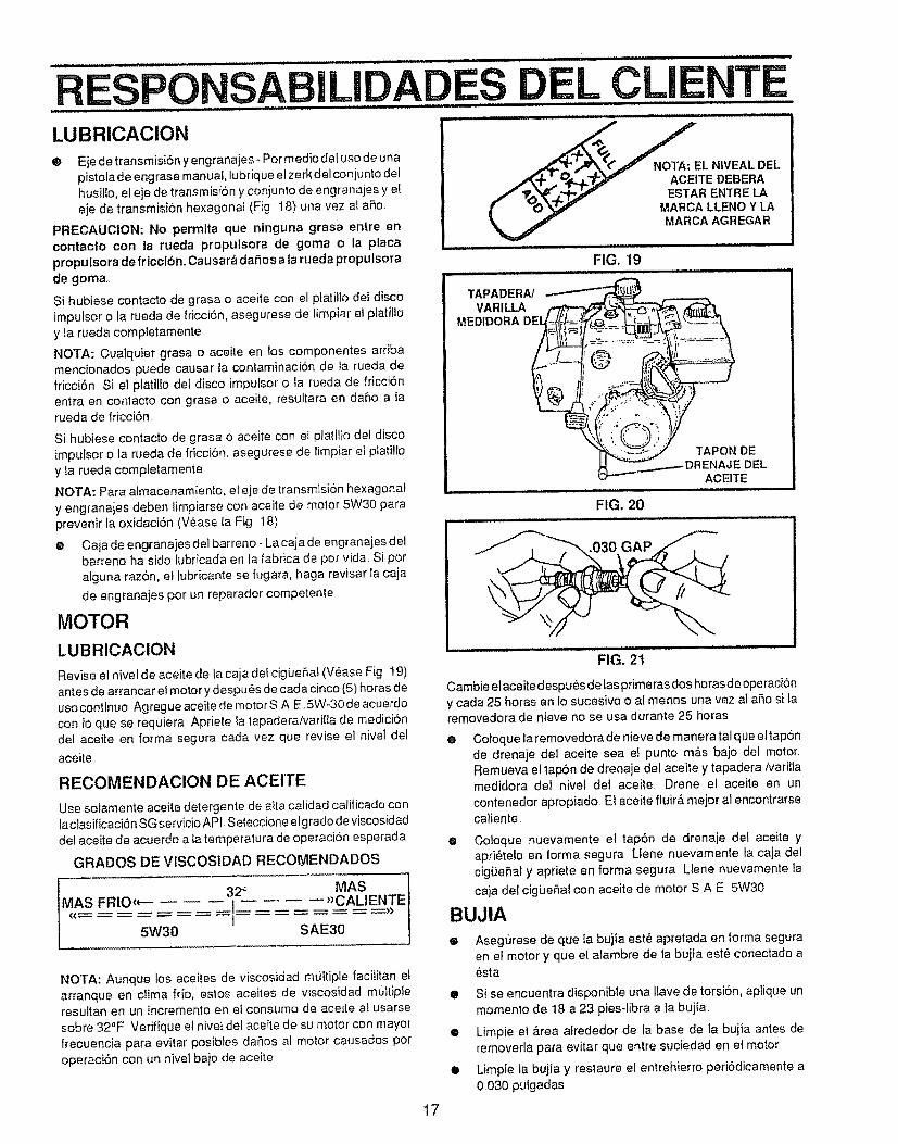
RESPONSABiLiDADES DEL CLIENTE= HH.,I _ ,_,_.................j. I =.,,, .......................''IHH ....... ................. lIH
LUBRICACION
@ Eje detransmisi6n yengranaies - Par media de5usa de unapistofa de engrase manual, lubrique efzerk del con junto delhusiffo, el eje de transmisi6n y conjunto de engranajes y eteje de transmisiSn hexagonal (Fig 18) una vez ai ar_o
PRECAUCtON: No perrnita que ninguna grasa entre enconlacto con la rueda propulsora de goma o la placaproputsora de friccibn_ Causar._ daSos a tarueda propulsorade goma,
Si hubiese contacto de grasa o aceite con el p_atitlo dei discoimpulsor o la rueda de fricci6n, asegurese de limpiar el platiltoy la rueda completamente.
NOTA: Cualquier grasa o aceite en los camponentes arribamencionados puede causar la contaminaci6n de ta rueda defricci6n Si el pJatil[o de! disco Jmpu[sor o {a rueda de fricci6nentra en contacto con grasa o aceite, resultara en da_,o a larueda de fricci6n..
Si hubiese contacto de grasa o aceite con et ptatitlo det discoimpulsor o la rueda de fricci6n, asegurese de limpiar et pIatilloy ta rueda completamente
NOTA: Para atmacenamiento, el eje de transmisi6n hexagonaly engranajes deben limpiarse con aceite de motor 5W30 paraprevenir la oxidaci6n (V6ase la Fig 18)
e Caja de engranajes del barreno- La caja de engranaies detbarreno ha sido lubricada en la f&brica de par vida Si paratguna razSn, el Iubficante se fugara, haga revisar la caja
de engranajes par un reparador competente
MOTOR
LUBRICACION
Revise e! nivel de aceite de la caja det cigue6at (Vease Fig 19)antes de arrancar el motor y despu6s de cada cinco (5) horas deusacontinua Agreg ueaceite de motors A E..5W-30 de acuerdocon io que se requiera Apriete la tapaderaNarilta de medicionde( aceite en forma segura cada vez que revise al nivel de!aceite
RECOMENDACION DE ACEITE
Use solamente aceite detergente de alta calidad calificado conla clasificaci6n SG servicio API Seteccione elg rado deviscosidaddet aceite de acuerdo a ta temperatura de operaci6n esperada
GRADOS DE VlSCOSIDAD RECOIYlENDADOS
MASMAS FRIO,*- __i 2_'_ "CALIENTE
/ == = -- = ="
NOTA: Aunque los aceJtes de viscosidad multiple facilitan elarranque en clima frio, estos aceites de viscosidad m_ttipteresultan en un incremento en el consumo de aceite al usarse
sabre 32°F Verifique el nivet del aceite de su motor con mayorfrecuencia para evitar posibles daSos at motor causados par
operaci6n con un nivel bajo de aceite
.,0._,__ZEL NIVEAL DEL
j,_+_ _.lkT_l v ACEITE DEBERA/ '_'0__"3_._ v ESTAR ENTRE LA_" _O _ MARCA LLENO Y LA
_=_" MARCA AGREGAR
FIG, 19i / i ......
TAPADERNVARILLA
MEDIDORA
FIG. 20
TAPON DEDEL
ACEITE
.030 GAP
FIG. 2t
Cambie el aceite despu_s de las primeras doshoras de operacibny cada 25 horas en Io sucesivo o a! menos una vez al a_o si laremovedora de nieve no se usa durante 25 horas
0 Coloque la removedora de nieve de manera tal que eltap6nde drenaje del aceite sea e! punto m_fisbajo del motor.Remueva el lap6n de drenaje det aceite y tapadera/varitlamedidora de/ nive/ del aceite Orene el aceite en un
contenedor apropiado Ei aceite fluir& mejor al encontrarsecaliente
@ Cotoque nuevamente el tap6n de drenaje del aceite yapri_te!o en lorma segura LIene nuevamente la caja de1cig(JeSaf y apriete en farina segura Llene nuevamente [a
caja del cigLieSal con aceite de motor S A E 5W30
BUJIA
® Asegurese de que la bujia est_ apretada en forma seguraen et motor y que el alambre de la buiia est_ conectado a_sta
• Si se encuentra disponibte una llave de torsi6n, aplique unmomenta de 18 a 23 pies-libra a la bujia_
• Limpie el &rea atrededor de _abase de la buiia antes deremoverla para evitar que entre suciedad en el motor
• Limpie la buj[a y restaure el entrehierro peri6dicamente a0B30 pulgadas
17
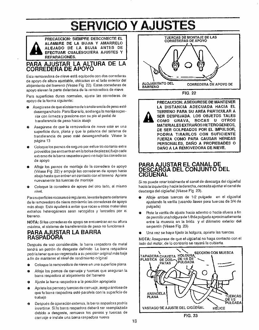
CIO Y AJUSTPRECAUCION: SiEMPRE DESCONECTE EL
_ ALAMBRE DE LA BUJIA Y AMARRELOALEJADO DE LA BUJIA ANTES DEEFECTUAR CUALESQUtERA AJUSTES YREPARACIONES.
PARA AJUSTAR LA ALTURA DE LACORREDERA DE APOYOEsta removedora de nieve est& equipada con dos correderas
de apoyo de altura ajustable, ubicadas en el lade exterior delalojamiento del barreno (V_ase Fig 22) Estas correderas deapoyo eievan ta parle delantera de la temovedora de nieve
Para superficies duras normales, ajuste las correderas de
apoyo de la forma siguiente:
O Aseg0rese de que elsistema detransferencia de peso estedesenganchado. Para tiberado, sostenga la manija super-riot con firmeza y presione con su pie el pedal detrans|erencia de peso hacia abajo.
@ Asegt]rese de que fa removedora de nieve est6 en unasuperficie dura, piana y que la palanca del sistema detransferencia de peso este desenganchada Vease la
p,_gina !3
® Coloque los pernos de seguro per esfuerzo cortante extraprovetdos (se encuentran en la bolsade piezas) ba]o cadaextreme de la barra raspadora pero no baio las correderas
de apoyo
o Afloje los pernos de montaje de la corredera de apoyo(V6ase Fig 22) y empuje las correderas de apoyo haciaabajo hasta que entren en contacto con elterreno Aprietenuevamente las tuercas de montaje
o Cotoque la corredera de apoyo del otto lade, ai mismonivel,
Para superficies recosas o irregulares, levante taparte delanterade la removedora de nieve moviendo las correderas de apoyom&s abajo Esto ayudar& a evitar que rocas u otros materialesextrahos heterog6neos sean recogidos y lanzados per elbarreno,
NOTA: Si Ias correderas de apoyo se encuentran en su alturam_.xima, ef sistema de transferencia de peso no funcionar&
PARA AJUSTAR LA BARRARASPADORA
Despues de uso considerable, la barra raspadora de metaltendr& un patr6n de desgaste definido La barra raspadora
podria tener que ser regresada a su posicion original m&s bajaa fin de mantener el nivel de rendimiento original
® Coloque la removedora de nieve en una superficie plana
e Afloje los pernos de carruaje y tuercas que aseguran iabarra raspadora al alojamiento del barreno
o Ajuste ]a barra raspadora a la posicion apropiada
e Apriete tos pemos ytuercas de carruaje, asegurandose de
que la barra raspadora est_ paralela con la superficie detrabajo
@ Despues de operaci6n extensa, la barra raspadora podriainvertirse,, Si la barra raspadora deber& set reemplazadadebido a desgaste, remueva los pernos y tuercas de
carruaje e instale una barra raspadora nueva18
TI}ERCAS DE MONTAJE DE LASCORREDERAS DE APOYO
ALOJAMtENTO DEL CORREDERA DE APOYO DEBARRENO
FIG, 22
PRECAUCION: ASEGURESE DE MANTENERLA DISTANCIA ADECUADA HACfA ELTERRENO PARA SU AREA PARTICULAR ASER DESPEJADAo LOS OBJETOS TALES
COMe GRAVA, ROCAS U OTROSMATERIALES EXTRAI_IOS HETEROGENEOS,DE SER GOLPEADOS PeR EL IMPULSOR,PODRIA TIRARLOS CON SUFICIENTEFUERZA COMe PARA CAUSAR HERIDASPERSONALES, DA_IO A PROPIEDADES ODANe A LA REMOVEDORA DE NIEVE.
PARA AJUSTAR EL CANAL DEDESCARGA DEL CONJUNTO DELClGUENAL
Si no puede rotar totalmente el canal de descarga del cigbeSalhacia la izquierda y hacia la derecha, necesita ajust ar el canal dedescarga del cig0eSal (V6ase Fig 23),
• Afloje ambas tuercas de 1t2 puLgada en el cigiJeSaiajustando la varilla (usando tlaves para tuercas de 3/4 depulgada)
• Rote la varilla de ajuste hacia adentro o hacia afuera a finde permitir una holgura de 1/8de pulgada aproxim adamenteentre la muesca en la brida y el di&melro exterior dei
serpentin (V_ase Fig 23).
® Una vez se haya tijado la holgura, apriete las tuercas
NOTA: Asegurese de que el cigiJeSal no haga contacto con ellade del motor, de lo contrario se rayar& la cubierta,
\ SECCION CON MUESCATAPADERA CHAVETA HOLGURA_PLASTICA DE 1/8 DE _.
PULGADA
PLANA DE 112
VASTAGO DE AJUSTE DEL ClGUEI_IAL HEUCE
FIG. 23
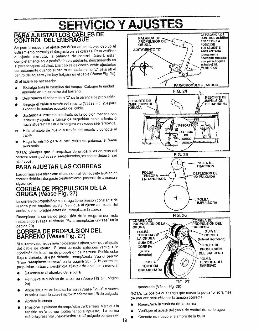
SERVIClOPARA"AJUSTAR LOS CABLES DE ....CONTROL DEE EMBRAGUE
Se podria requerir et ajuste peri6dico de los cables debido afestiramiento normal y et desgaste en las correas Para verificarel ajuste correcto, ta palanca de control deber& estarcompletamente en la posiciOn hacia adelante, descansando en
el parachoques pl&sticoo Los cables de contro_ est&n ajustadoscorrectamente cuando el centro del aditamento 'Z" est& en et
centro de_agujero y no hay holgura en el cable (Vease Fig 24)
Si el ajuste es necesario:
o Extraiga toda fa gasolina del tanque Coloque la unidadapoyada en un extremo de_ barreno
Y AJUSTESPALANCA DEPROPULSIONORUGA
e Desconecte el aditamenlo"Z" de la palanca de propulsion.
® Empuje el cable a traves del resorte (V_ase Fig. 25) paraexponer la porci6n roscada del cable
® Sostenga el extremo cuadrado de la porci6n roscada contenazas y ajuste la tuerca de seguridad hacia adentro ohacia afuera hasta que la holgura en exceso sea removida
RESORTEDEIMPULSION DEORUGA
FiG.24....................
• Hate el cable de nuevo a traves del resorte y conecte elcable..
..............LAPAL'_'NCAD_'_CONTROL DEBER,_ESTARENLAPOSICIONTOTALMENTEADELANTADA(dusl'amentehaciondoconlactocon parachoquesptdsltco) ALVER|FICAR
PLASTICQ..........
® Haga {o mismo para ef otto cable de palanca, si fuesenecesario
NOTA: Siempre que el propulsor de oruga o las correas delbarreno sean ajustadas o reemplazadas, los cables deberan set
ajustados.
PARA AJUSTAR LAS CORREAS
Las correas se estiran con el uso normal Si necesita ajuslar iascorreas @ebidoa desgaste o estiramiento, proceda de la manerasiguiente:
CORREA DE PROPULSION DE LAORUGA (Vease Fig. 27)La correa de proputsi6n de la oruga tiene presi6n constante deresorte y no requiere ajuste. Verifique el ajuste del cable del
control del embrague antes de reemplazar la correa
Reemplace la correa de proputsi6n de la oruga si aun est,.resbaiando (V,_ase el pkrralo "Para reemplazar correas" en lapagina 20),
CORREA DE PROPULSION DELBARRENO (V_ase Fig. 27)Si su removedorade nieve no descarga nieve, verifique ef aiustedet cable de control Si esta correcto entonces veritique tacondici6n de la correa de propulsion del b'arreno Podria estarfloja o dafada Siesta da5ada, reempt&ceta Vea el p&rrafo"Para reemplazar correas" en la p&gina 20) Si la correa de
propulsion del barreno est_ floja, aj0stela de la siguiente manera:
o Desconecte ef alambre de ta bujia
II Remueva la cubierla de ta correa (Vease Fig 28, p&gina2O)
• Aftoje latuerca en ta polea tensora (V6ase Fig 26) y muevaIa polea hacia la correa aproximadamente 1/8 de pu/gada
• Apt!ere la tuerca
• Presione la patanca de propulsi6n dot barreno Verifique latensi6n en la correa (polea tensora opuesta) La correadeberia prose ntar una deflexion de 1/2 putgada con presi6n
19
POLEATENSORAENGANCHADA
FIG. 25
DEFLEXION DEPULGADA
POLEAIMPULSORA
FIG. 26
DE
TENSORA DELBARRENO
FIG. 27
moderada (V_ase Fig 26).
NOTA: Es posible que tenga que mover ia potea tensora m,_sde una vez para obtenet' la tension correcla
$ Reempface la cubiena de la correa
$ Verifique el ajuste del cable de contro! del embrague.
It Conecte de nuevo el alambre de la bujia
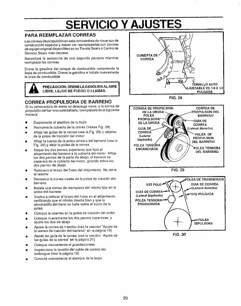
SERVIClO Y AJUSTESPARA REEMPLAZAR CORREAS
Las cotreas de propulsi6n en esta removedora de nieve son deconstrucciSn especial y deben ser reemplazadas con correasde equipo original disponibles en su Tienda Sears o Centro deServicio Sears m&s cercano,
Necesitar& fa asistencia de una segunda persona mientrasreemplaza fas correas
Drene la gasolina det tanque de combustible removiendo Ialinea de combustible,. Drene la gasolina e instale nuevamenteta Linea de combustible,
PRECAUCION: DRENE LA GASOUNA AL AIRE 1LIBRE, LEJOS DE FUEGO O LLAMAS.
CORREA PROPULSORA DE BARRENOSi su removedora de nieve no descarga nieve, y la correa depropulsi6n dei barreno est&daSada, reempl&cela de la siguientemanera:
• Desconecte et alambre de ta bujia
• Remueva la cubierta de la correa (Vease Fig 28)
• Afloje las guias de la correa (yea fa Fig 29) y al6jeiasde ta potea de tracci6n del motor
• Afloje la tuerca de la polea tensora del barreno (vea taFig 30) y ateje la polea de ta correa
e Saque los dos pemos superiores que fijan elaiojamiento det barreno a Ia cubierta det motor Aflojelos dos pernos de la parte de abajo; el barreno seseparar& de ia cubierta del motor, girando sobre tosdos pemos de abajo
• Remueva el brazo det freno del alojamiento No retireel resorte
• Remueva {a correa usada de {a potea de tracci6n detbarreno,.
e Instale una correa de reempiazo del mismo tipo en lapolea del barreno,
e Vue]va a colocat el brazo del freno en et alojamiento,verificando que eI mismo inserte bien y que laalmohadifla del freno se halle sobre el surco de la
polea,
• Co]oque la coarrea en la polea de traccion del motor
• Coloque nuevamente !os dos pernos superio_es, yajuste los dos de abajo
• Ajuste la correa de traccion (yea ia secci6n "Ajuste deia correa de tracci6n del barreno" en la pagina 19)
• Ajuste las guia de la correa (yea la secci6n "Ajuste delas guias de la correa" en la p&gina 21)
e Coloque neuvamente el guardacorreas
• [nspeccione la tensi6n del cable de control detembrague (vea la p&gina 19)
• Conecte nuevamente e] aiambre de ta bujia
CUBIERTA DECORREA /
FIG. 28
T_)RN|LLO AUTO
_AJUSTABLE DE 114 X 1t,'PULGADA
CORREA DE PROPULSIONDEPOLEA
DE LA ORUGA
GUIA DECORREA(Lateral
izquterdo)
POLEA TENSORAENGANCHADA
CORREA DE)ULSION DEL
BARRENO
DECORREA
(Lateral derecho)
DEPROPULSION
DEL BARRENO
TENSORADEL BARRENO
................................FIG. 29_'
, _4'.,,,._ _*POLEA DE TRANSMISION
3/32 PULG "4_&_ j____---- _ GUlA DE CORREA
_k _--)_ _.d_-*(Latm'al derecho)GUIA DECORREA -'_'_ _ _.='
(Lateral Izqu,erdo) _ _,._"3t32 PULGADAPOLEA TENSORA-'="t_._ ..,/ \"
ENGANCHADA _
I . ,.-L_,, .. _.,.,_ POLEA
_ ! - / IMPULSORA
FIG. 30
20
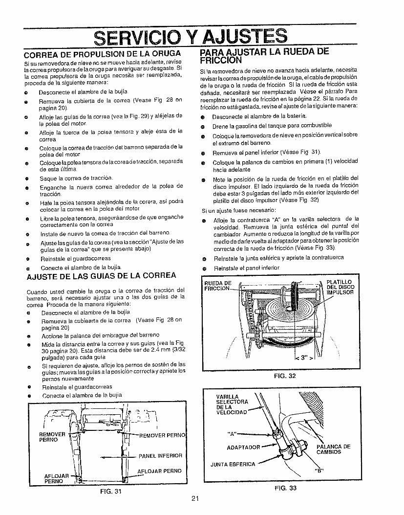
SERVICIO Y AJUSTESu,,,,,,,,ll m i1,1 r : .... .................. .............
CORREA DE PROPULSION DE LA ORUGA PARA AJUSTAR LA RUEDA DESi su removedora de nieve no se mueve hacia adelante, revise FRICCIONla correa propulsora de [a oruga para averiguar su desgaste. Sila correa propulsora de la oruga necesita ser reemplazada,proceda de la siguiente manera:
G
G
0
0
0
®
0
®
0
@
0
0
O
0
Desconecte el alambre de la bujfa
Remt_eva _acubierta de la correa (Vease Fig 28 onpagina 20).
Afloje las guias de la correa (yea la Fig 29) y al_jelas dela poiea del motor.
Afloje ta tuerca de la polea tensora y aleje esta de tacorrea
Si la _'emovedora de nieve no avanza hacia adelante, necesita
revisar lacorrea de proputsi6n de lao rug a, elcable de propu fsi6nde la oruga o la rueda de friccion Si la rueda de fricci6n estadafada, necesitar& ser reempiazada. V_ase el p&rrafo Parareemplazar la rueda de fricci6n en ta p_gina 22. Si la rueda defricci6n no est& gastada, revise el ajuste de la siguiente manera:
Coloque ta correa de tracciSn del barreno separada de lapolea del motor
Coloquela poleatensorade lacorea detracciOn, separadade esta ['Jttima
Saque la correa de tracci6n.
Enganche la nueva correa alrededor de fa potea detracciOn.
Hale ta polea tensora alej&ndola de la corera, asi podr&colocar la correa en fa potea del motor
Libre la polea tensora, asegura, andose de que enganchecorrectamente con la correa
lnstale de nuevo la correa de traccion del barreno
Ajuste fas gufas de la cerrea (yea la secciOn "Ajuste de tasguias de la correa" que se presenla abajo)
Reinstale el guardacorreas
Conecte et alambre de la buiia
• Desconecte el alambre de la bateria.
O Drene la gasolina del tanque para combustible
@ Cotoque la removedora de nieve en posiciSn verticalsobreel extremo del barreno,
@ Remueva et panel inferior (V_ase Fig 3!).
® Coloque la palanca de cambios en primera (1) velocidadhacia adelante.
® Note la posiciSn de la rueda de fricciSn en el platiiIo deldisco impulsor, El lade izquierdo de la rueda de fricci6ndebe estar 3 pulgadas del lado m&s exterior izquierdo delplatillo del disco impulsor (V_ase Fig 32)
AJUSTE DE LAS GUIAS DE LA CORREA
Si un ajuste fuese necesario:
@ Afloje la contratuerca "A" en la varilla selectora de lave!ocidad Remueva ta junta esf_rica del puntal delcambiador Aumente o reduzca la longitud de la varilta pormedio de darle vuelta al adaptador para obtener laposictSncorrecta de la rueda de fricci6n (V_ase Fig 33)
® Reinstate la junta esf_rica y apriete la contratuerca.
® Reinstale etpanef inferior
Cuando usted cambie la oruga o la correa de tracci6n delbarreno, set& necesario ajustar una o tas dos guias de lacorrea Proceda de la manera siguiente:
• Desconecte el alambre de la bujia
e Remueva la cubiearta de la correa (Vease Fig 28 onpagina 20)
• Accione ta palanca def embrague del barreno
• Mida la distancia entre la correa y sus guias (yea _aFig30 pagina 20). Esta distancia debe ser de 2.4 mm (3/32pulgada) para cada guia
e Si requieren de ajuste, afloje tos pernos de sost_n de lasguias; mueva tas guias a la posicl6n correcta y apriete lospernos nuevamente
o Reinstale el guardacorreas
• Conecte el atambre de la bujiaH,,i, ....
REMOVER __ '
FIG. 31
RUEDA DE PLATILLODEL DISCOIMPULSOR
FIG. 32
VARILLA _'\'_\SELECTORA \_\DELA
w,oc,D O"-
ADAPTADOR
JUNTA ESFERtCA JDE
FIG, 33
21
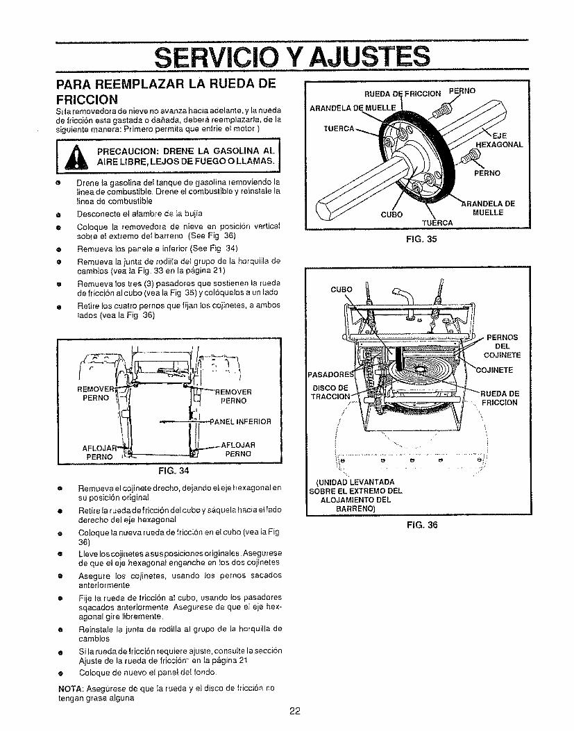
SERVICIO Y AJUSTESPARA REEMPLAZAR LA RUEDA DE ...................FRICCIONSi la removedor a de nieve no avanza hacia adeiante, y la nuedade fricciSn esta gastada o daSada, debera reemplazaria, de lasiguiente manera: Primero permita qua enffie el motor)
PRECAUClON: DRENE LA GASOLINA ALi -
AIRE LIBRE, LEJOS DE FUEGO O LLAMAS. IO Drene ta gasolina del tanque de gasolina removiando ta
linea de combustible Drene el combustible y reinstale latinea de combustible
e Desconecte el alambre de la bujia
e Coloque la removedora de nieve en posicion vertica_sobt'e el extremo del barrer_o (See Fig 36)
e Remueva los panete e inferior (See Fig 34)
• Remueva ta junta de rodilla del grupo de la horquilla decambios (vea ]a Fig._33 en la p&gina 21)
e Remueva los tres (3) pasadores qua sostienen ta ruedade fricciSn ai cubo (yea la Fig 35) y coloquelos a un lado
• Retire los cuatro pernos qua fijan los cojinetes, a amboslados (yea la Fig 36)
REMOVE ' ---.-,I°VE v REMOVERP ..o j?
"_ ANEL INFERIOR
AFLOJAR .._--AFLOJAR
FtGo 34
e Remueva el cojinete drecho, dejando el eje hexagonal er_su posici6n original.
e Retire la ruedade friccion del cubo y s&quela hacia el ladoderecho del eje hexagonal
• Coloque la nueva rueda de friccion en el cubo (yea la Fig36)
• Lleve los cojinetes a sus posiciones originales Aseguresede que el eje hexagonal enganche en los dos cojinetes
• Asegure los cojinetes, usando los pernos sacadosanteriormente.
e
o
e
Fije fa rueda de fricci6n aI cubo, usando {os pasadoressqacados anteriormente Asegurese de qua el eje hex-agonal gire libremente
Reinstale la junta de rodilta al grupo de la horquilla decambios
Si ta rueda de lricci6n l'equiere ajus_,e,consuile la secci6nAjuste de la rueda de fricci6n en la pagina 21
Cotoque de nuevo e] panel del rondo.
NOTA: Asegurese de qua ta rueda y el disco de fficciSn notengan grasa alguna
ARANDELA DE MUELLE
',FRICCION PERNO
,EJEHEXAGONAL
PERNO
CUBO MUELLETUERCA
FIG, 35
DE
CUBO
PERNOSDEL
COJfNETE
TR _UEDA DE.. FRICC|ON
.J
/,f _',
% .......................... . :.::''
(UNIDAD LEVANTADASOBRE EL EXTREMO DEL
ALOJAM1ENTODEL8ARRENO)
FIG. 36
22
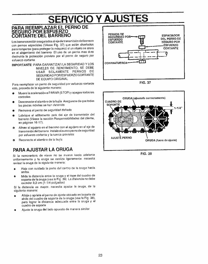
SERVICIOPARA REEMPLAZAR......................................................EL PERNO DESEGURO POR ESFUERZOCORTANTE DEL BARRENOLos barrenos est&n asegurados al eje detransmisi6n defbarreno
con pernos especiales (V_ase Fig. 37) que est&n diseSadospara rornperse (para proteger ta m&quina) si un objeto se atoraen et atojamiento del barreno Et uso de un perno rnas duro
destruiria la proteccion provista pot el perno de seguro potesfuerzo cortante
IMPORTANTE: PARA GARANTIZAR LA SEGURIDAD Y LOS
NIVELES DE RENDIMIENTO, SE DEBEUSAR SOLAMENTE PERNOS DESEGURIDAD POR ESFUERZOCORTANTEDE EQUfPO ORIGINAL
Para reempiazar un perno de seguridad pot esfuerzo cortanteroto, proceda de ta siguiente manera:
e Mueva ta aceleracibn a PARAR (STOP) y apague todos toscontroies.
• Desconecte el a_arnbrede la bujia Asegurese de que todas{as piezas m6viles se han detenido
• Remueva el perno de seguridad dahado
O Lubrique e! aditamento zerk det eje de transmisi6n delbarreno (V§ase la secciSn Responsabilidades de! diente,en p&ginas 16-I7).
e Aiinee el aguiero en e] barreno con e! agujero en e! eje detransmisi6ndelbarreno Instale einuevopernodeseguridadpor esfuerzo cortante y la tuerca provistos
e Reconecte el alambre de la buiia
PARA AJUSTAR LA ORUGASi la rernovedora de nieve no se mueve hacia adelante
uniforrnemente y ta oruga se desliza ligerarnente, necesitarevisar ta oruga de la siguiente rnanera:
o Hale con cuidado la parIe del centro de ia oruga haciaarriba,
• Mida la distancia entre {a oruga y e! tope del cuadro desoporte de la oruga (yea la Fig 38) La distancia no debeexceder 3,2 cm (1-t/4 pulgadas)
Si ta distancia es mayor, necesita aiustar la oruga, de lasiguiente rnanera:
• Afloje o apriete el perno de ajuste ubicado en ta parte deaires del cuadro de soporte de la oruga (yea la Fig 38),para iograr la distancia adecuada entre ta oruga y elcuadro de soporte
• Aiuste la oruga del tado opuesto de rnanera similar
Y AJUSTES: i ii, n,iH,,Uln ni .... n I1'1I
PERNOS DESEGURIDADPOR_ ESPACIADORESFUERZO _ DEL PERNO DECORTANTE _ SEGURO POR
.._ESFUERZOCORTANTE
FIG. 37
CUADRO DESOPORTE
ORUGA (ajustada correctamente)
AJUSTE PERNO
ORUGA (fuera de ajuste)
FIG. 38
23
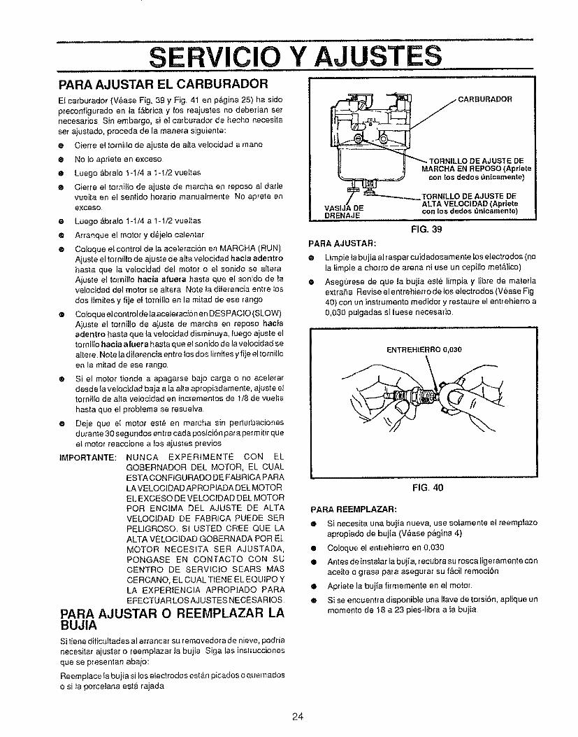
SERVICIO Y AJUSTESPARA AJUSTAR EL CARBURADOREI carburador (V6ase Fig, 39 y Fig, 41 en p_gina 25) ha side
preconfigurado en la f&brica y los reajustes no deberian setnecesarios Sin embargo, si el carburador de becho necesita
set ajustado, proceda de la manera siguiente:
• Cier_e el tornillo de ajuste de alta velocidad a mane
® No lo apriete en exceso
e Luego Abralo 1-1/4 a t-i/2 vue!tas
® Cierre el tornillo de ajuste de marcha en repose al darlevuelta en el sentido horario manuatmente No aprete en
exceso
® Luego Abralo 1-1/4 a 1-1/2 vueitas
• Artanque e! motor y d_jelo calenlar
• Coloque el control de la aceleracion en MARCHA (RUN)Ajuste el tornilio de ajuste de alia velocidad hecla adentrohaste que la velocidad del motor o el sonido se aiteraAjuste el tornil{o haole afuera haste que el sonido de tavelocidad del motor se altera Note ia dife{encia entre los
dos lfmites y fije el tornilto en la mired de ese range
• Coloque elcontrolde laaceleracionen DESPACIO (SLOW)Ajuste et tomiUo de ajuste de marcha en repose haciaadentro haste que ta velocidad disminuya, luego ajuste eltornillo hacia afuera haste que ei sonido de la velocidad sealtere, Note la diferencia entre los dos limites y fije el tornillo
en la mitad de ese tango,
® Si el motor tiende a apagarse bajo carga o no acelerardesde Ia velocidad baja ala alia apropiadamente, ajuste ettornillo de alia velocidad en incrementos de t/8 de vuelta
haste que el problema se resuefva
O Deje que e! motor est_ en marcha sin perturbacionesd urante 30 segundos entre cada posici6n pare perm itir queet motor reaccione a los ajustes previos,
IMPORTANTE: NUNCA EXPERIMENTE CON ELGOBERNADOR DEL MOTOR, EL CUALESTA CONFtGURAOO DE FABRfCA PARALA VELOCtDAD APROPIADA DEL MOTOREL EXGESO DE VELOCIDAD DEL MOTORPeR ENCIMA DEL AJUSTE DE ALTAVELOCtDAD DE FABRICA PUEDE SER
PELIGROSO, St USTED CREE QUE LAALTA VELOCIDAD GOBERNADA PeR ELMOTOR NECESITA SER AJUSTADA,PONGASE EN CONTACTO CON SUCENTRe DE SERVtCtO SEARS MAS
CERCANO, EL CUAL TtENE EL EQUIPO YLA EXPERIENCIA APROPIADO PARA
EFECTUAR LOS AJUSTES NECESARIOS,_
PARA AjUSTAR O REEMPLAZAR LABUJIA
DE AJUS3"E DEMARCHA EN REPOSe (Apriete
con los dedos bnicamente)
TORN|LLO DE AJUSTE DEALTA VELOCIDAD (Apriete
DE con los dedos _nicamente)DRENAJE
FIG. 39
PARA AJUSTAR:
®
e
Limpie la bujia al raspar cuidadosame nte los electrodes (nola limpie a chorro de arena ni use un cepillo mete,lice)
Asegorese de que la bujta esle limpia y libre de materiaextraSa Revise el entrehierro de los electrodes (V_ase Fig,
40} con un instrumento medidor y restaure el entrehierro a0,030 pulgadas si tuese necesario,
ENTREHIERRO 0,030
FIG, 40
PARA REEMPLAZAR:
® Si necesita una bujia nueva, use sotamente el reempiazo
apropiado de bujia (V_ase pagina 4),
• Coloque el entrehierro en 0,030
• Antes de instatar ta bujia, [ecubra su rosca ligeramente conaceite o grasa para asegurar su f&cil remociSn
e Apriete la bujia fifmemente en el motor,
e si se encuentra disponible una Ilave de torsi6n, aptique unmemento de 18 a 23 pies-libra ala bujia
Si tiene dificuftades al arrancar su removedora de nieve, podtia
necesitar ajustar o reemplazar la bujia Siga las instrucciones
que se presentan abajo:
Reemplace la bujia si los electrodes estan picados o quemadoso si la porceiana est_ rajada
24
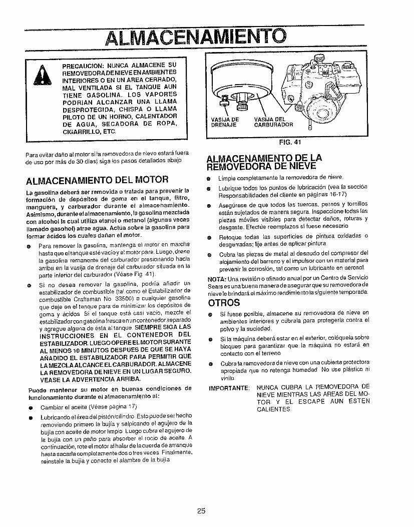
ALIVlACENAMIENTOll,ll,,,l,
PRECAUCION: NUNCA ALMACENE SUREMOVEDORA DE NIEVE EN AMBIENTES
INTERIORES O EN UN AREA CERRADO,MAL VENTILADA SI EL TANQUE AUNTIENE GASOLINA, LOS VAPORESPODR|AN ALCANZAR UNA LLAMA
DESPROTEGIDA, CHISPA O LLAMAPILO'FO DE UN HORN@, CALENTADORDE AGUA, SECADORA DE ROPA,CIGARRILLO, ETCo
Para evitar da_o al motor si ta removedora de nieve estara rue ra
de us@por m&s de 30 dlas) siga tospasos detaliados abaio
ALMACENAMIENTO DEL MOTOR
VASIJA DE VASIJA DELDRENAJE CARBURADOR
La gasolina deber_ set removida o tratada para prey@nit laformactbn de dep6sitos de goma en el tanque, filtro,manguera, y carburador durante el almacenamiento.Asirnismo, durante el almacenamIento, la ga solina mezc_ada
con alcohol la cuat utfliza etanol o metanol (algunas vecesIlamado gasohol) atrae agua.. Actua sobre la gasolina paraformar acidos los cuales daSan el motor..
O
@
Para remover la gasolina, mantenga el molor en marchahasta que eltanque estevacioy et motor pare Luego, drenefa gasolina remanente det carburador presionando haciaarriba en la vasija de drenaje del carburador situada en lapart@ inferior de! carburador (Vease Fig 4t)
Si no desea remover la gasolina, podria a_adir unestabilizador de combustible (tal corn@ et Estabiiizador decombustibte Craftsman No 33500) a cualquier gasolinaque deje en e{ tanque para de minimizar tos depositos degoma y &cidos Si el tanque @st&casi vacio, mezcie elestabilizador con gasolina fresca e nun conten edor separadoy agregue alguna de _sta aI tanque SIEMPRE SIGA LAStNSTRUCCIONES EN EL CONTENEDOFI DELESTABILlZADOR.. LUEGOOPERE ELMOTOR SURANTEAL MENOS 10 MINUTOS DESPUES DE QUE SE HAYAAI_IADIDO EL ESTABILIZADOR PARA PERM|TIR QUELA MEZCLA ALCANCE EL CARBURADOR ALMACENE
LA REMOVEDORA DE NIEVE EN UN LUGAR SEGUROoVEASE LA ADVERTENCIA ARRIBA,,
Puede mantener su motor en buenas condiciones defunciorlamtento durarite el almacenamiento al:
@ Cambiar el aceite (V_ase p,_gina !7)
@ Lubricando eiareadetpistbn/cilindro Estopuede set hechoremoviendo primer@ fa bujia y salpicando el agujero de labuj{a con aceite de motor limpio Luego cubra eI agujero deta bujia con un paso para absorber et rocio de aceite Acontin uaciOn0rote el motor a! hafar de la cuerda de arranq uehasta sacarla completamente dos otres veces Finatmente,reinstale la bujfa y conecte e_atambre de ta bujia
FIG. 41
ALMACENAMIENTO DE LAREMOVEDORA DE NIEVE
@ Limpie completamente la removedora de nieve..
• Lubrique todos !os puntos de tubricaci6n (yea la secci6nResponsabitidades del ciiente en p_ginas 16.-t7)
e Asegurese de que todos las tuercas, pernos y torni_losest&n sujetados de manera segura. Inspeccione todas Iaspiezas m6viies visibles para detectar daSos, roturas ydesgaste Efectue reemplazos si fuese necesario
@ Retoque todas las superficies de pintura oxidadas odesgarradas; liie antes de aplicar pintura
@ Cubra las piezas de metal at desnudo del compresor det
alojamiento def barreno y el imputsor con un material paraprevenir la corrosi6n, tat como un lubricante en aerosol
NOTA: Una revisi6n o afinado anua[ por un Centro de ServicioSears es una buena manerade asegurar que su removedor adenieve lebrindar_ el m&×imo rendimie nto ta siguiente temporada
OTROS
e Si fuese posibie, almacene su removedora de nieve enambientes interiores y c_brala para protegerla contra etpolvo y la suciedad
e Si fa m&quina deber_. @star en e! exterior, coF6queia sobrebloques para garantizar que {a m&quina no estar_ encontact@ con el torten@
@ Cubra ta removedora de nieve con una cubierta protectoraapropiada que no retenga humedad No use p!&sgco nivinilo,
IMPORTANTE: NUNCA CUBRA LA REMOVEDORA DENIEVE MIENTRAS LAS AREAS DEL MO-TOR Y EL ESCAPE AUN ESTENCAL1ENTES
25
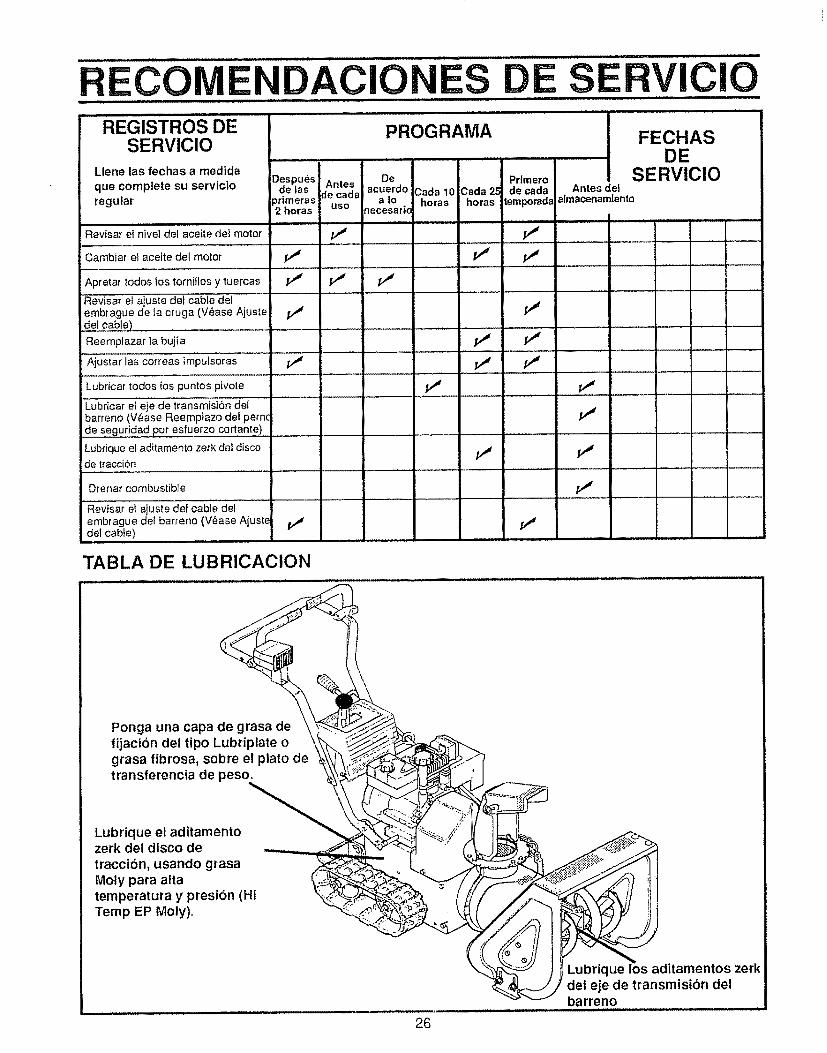
ECO DACIO S.................REGiSTROS DE
SERVICIOLlene las fechas a medida
Despuesque complete su servicto de las
regular _rimeras2 horas
Revisar el nive] del aceite de1 motor
Cambiar el aceite del motor V #,, ,,,,..................
Apretar todos los torniHos y tuercas
Revisar el ajuste del cable del ..........embrague de fa oruga (V_ase Ajustede{ cable) ...................
Reemplazar ]a bujia
.... _Ajust _r I I'a'scorreas im'puis'or'as J
Lubricar todos los puntos pivote
PROGRAMA
De PrlmeroAntes acuerdo 3ada 10 Cada 25 decada Antesdel
de cada a io horas horas l_porad_ almacenamlentouse necesar|c
v" v"
ClO
FECHASDE
SERVlClO
............ =
Lubricar ei eie de transmisi6n detbarTeno (Vease Reemp_azo del pernc
de seguridad pot esfuerzo cortante) .....
Lubrique el aditamento zerk dei disco /_ /._de tracci6n ..................
Drenar combustible
"Revisar el ajuste def cable det
embrague del barreno {V_ase Ajust_ j_del cable) ..............................
TABLA DE LUBRICACION
Ponga una capa de grasa defijacibn del tipo Lubriplate ograsa fibrosa, sobre el plato detransferencia de peso.
Lubrique el aditamentozerk del disco detraccibn, usando grasaMoty para altatemperatura y presion (HiTemp EP Moly),
26
Lubrique los aditamentos zerkdei eje de transmisibn delbarreno
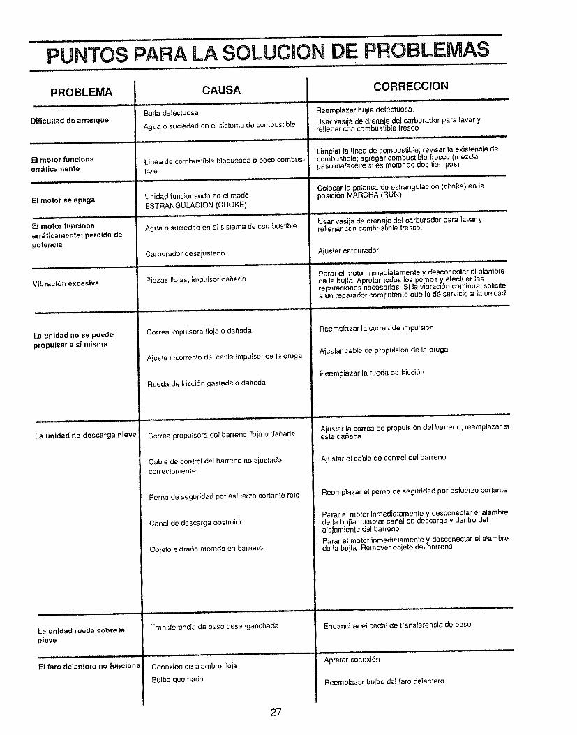
PUNTOS PARA LA SOLUCION DE PROBLEMAS
PROBLEMA
Dificultad de arranque
El motor funcionaerr_ticamente
El motor seapaga
El motor funciona
errdticamente; perdida depotencia
Vtbraci6n excesiva
La unidad no se puedepropulsar a si mlsma
La urtldad no descarga nteve
La unldad rueda sobre lanieve
El faro delantero no furJcIona
CAUSA
Buiia defectuosa
Agua o suciedad en el sistema de combustible
Ltnea de combustible bloqueada o poco combus-tible
Unidad funcionando en el mode
ESTRANGULACION (CHOKE)
Agua o suciedad en el sistema de combustible
Carburador desajustado
Piezas tlojas; impulsor da5ado
Correa impulsora floja o daSada
Ajuste incorrecto del cable impulsor de ta oruga
Rueda de fricci6n gas_ada o da_ada
Correa propuIsora del barreno floja o daSada
Cable de control del barreno no aiustadocorreclamente
Perno de seguddad por esfuerzo cortante rote
Canal de descarga obslruido
Objeto e×trmfio atorado en barreno
Transferencia de peso desenganchada
Conexi6n de alambre floja
Bulbo quemado
CORRECClON
Reemptazar bujfa defectuosa,
Usar vasija de drenaje del carburador para lavar yre!tenar con combustible fresco
Limpiar la linea de combustible; revisar la existencia decombustible; agregar combustible fresco (mezclagasolina/aceite si es motor de dos tiempos)
. u i ,i
Co!ocar la pafanca de estrangulacion (choke) en laposici6n MARCHA (RUN)
Usar vasija de drenaje del carburador para lavar yrellenar con combustible fresco
Ajustar carburador
Parar el motor inmediatamente y desconectar el alambrede la bujia Apretar todos los pernos y efectuar lasreparaclones necesarias Sila vibraciSn continua, solicitea un reparador competente que le de servicio a ta unidad
Reemplazar la correa de imputsi6n
Ajustar cable de propulsi6n de la oruga
Reemplazar ia rueda de fricci6n
Ajustar la correa de propulsiSn del barreno; reemplazar siesta daiSada
Ajuslar el cable de control del barreno
Reempiazar el pemo de seguridad pot esfuerzo cortante
Parar el motor inmediatamente y desconectar el alambrede ta bujia Limpiar canal de descarga y dentro delalojamienfo del barreno
Parar e! motor inmediatamente y desconectar el atambrede la bujia Remover objeto de! barreno
Enganchar el pedal de translerencia de peso
Apretar conexi6n
Reemplazar bulbo det faro delantero
27
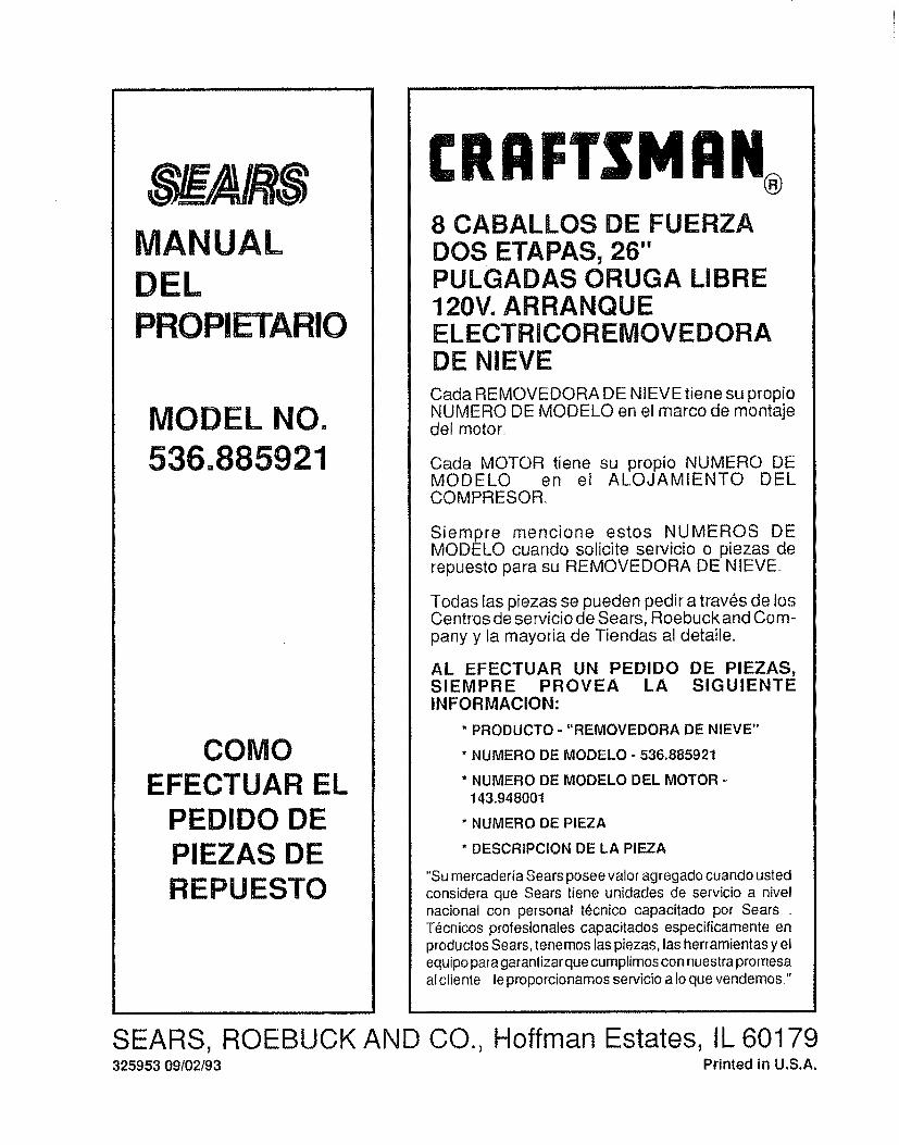
DEL
UAL
MODEL NO.536. 1
COMOEFECTUAR EL
PEDIDO DEPIEZAS DEREPUESTO
CRRFTSMRN®
8 CABALLOS DE FUERZADOS ETAPAS, 26"PULGADAS ORUGA LIBRE120V. ARRANQUEELECTRICOREMOVEDORADE NIEVE
Cada REMOVEDORA DE NIEVE tiene su propioNUMERO DE MODELO en el marco de montajedel motor.
Cada MOTOR tiene su propio NUMERO DEMODELO en el ALOJAMIENTO DELCOMPRESOR
Siempre mencione estos NUMEROS DEMODELO cuando solicite servicio o piezas derepuesto para su REMOVEDORA DE NIEVE.
Todas las piezas se pueden pedir a trav_s de losCentros de servicio de Sears, Roebuck and Com-pany y la mayoria de Tiendas al detaile,,
AL EFECTUAR UN PEDIDO DE PIEZAS,SlEMPRE PROVEA LA SlGUIENTEINFORMAClON:
* PRODUCTO -"REMOVEDORA DE NIEVE"
* NUMERO DE MODELO - 536.885921
* NUMERO DE MODELO DEL MOTOR14&94800t
* NUMERO DE PIEZA
* DESCRIPCiON DE LA PIEZA
"Su mercaderia Sears posee valor agregado cuando ustedconsidera que Sears tiene unidades de servicio a nivelnacional con personal t_cnico capacitado por Sears ....T6cnicos profesionales capacitados especificamente enproductos Sears, tene mos las piezas, las herramientas y elequipo para garanlizarque curnplimos con nuestra promesaal cliente,, le proporcionamos servicio a fo que vendemos?
SEARS, ROEBUCK AND CO., Hoffman Estates, tL 60179325953 09102t93 Printed in U.S.A_