Embed Size (px)
Citation preview

ISET Journal of Earthquake Technology, Paper No. 510, Vol. 47, No. 2-4, June-Dec. 2010, pp. 61–74
IMPORTANCE OF SITE-SPECIFIC STUDIES FOR MEDIUM SOIL SITES OF DELHI REGION
P. Kamatchi*, G.V. Ramana** and A.K. Nagpal** *Structural Engineering Research Centre, CSIR Campus, Taramani, Chennai-600113
**Department of Civil Engineering, IIT Delhi, Hauz Khas, New Delhi-110016
ABSTRACT
The importance of the effects of sediments above bedrock in modifying the strong ground motion has been long recognized. To account for this, some codes of practice incorporate individual response spectra for different types of soil. As an improvement over this, the amplification factors derived out of empirical and theoretical data are suggested in some of the international seismic codes for different site classes. In these codes, site-specific analysis has been recommended for the soft soil type (i.e., Site Class F). In this paper, the importance of site-specific response for three actual medium soil sites of Delhi is investigated. For this the scenario earthquakes from the Himalayan region as reported in the literature are chosen. It is demonstrated that for the Delhi region it may be necessary to perform site-specific analyses also for the buildings at the sites having medium types of soil.
KEYWORDS: Site-Specific Analysis, Delhi, Strong Ground Motion Generation, Soil Amplification
INTRODUCTION
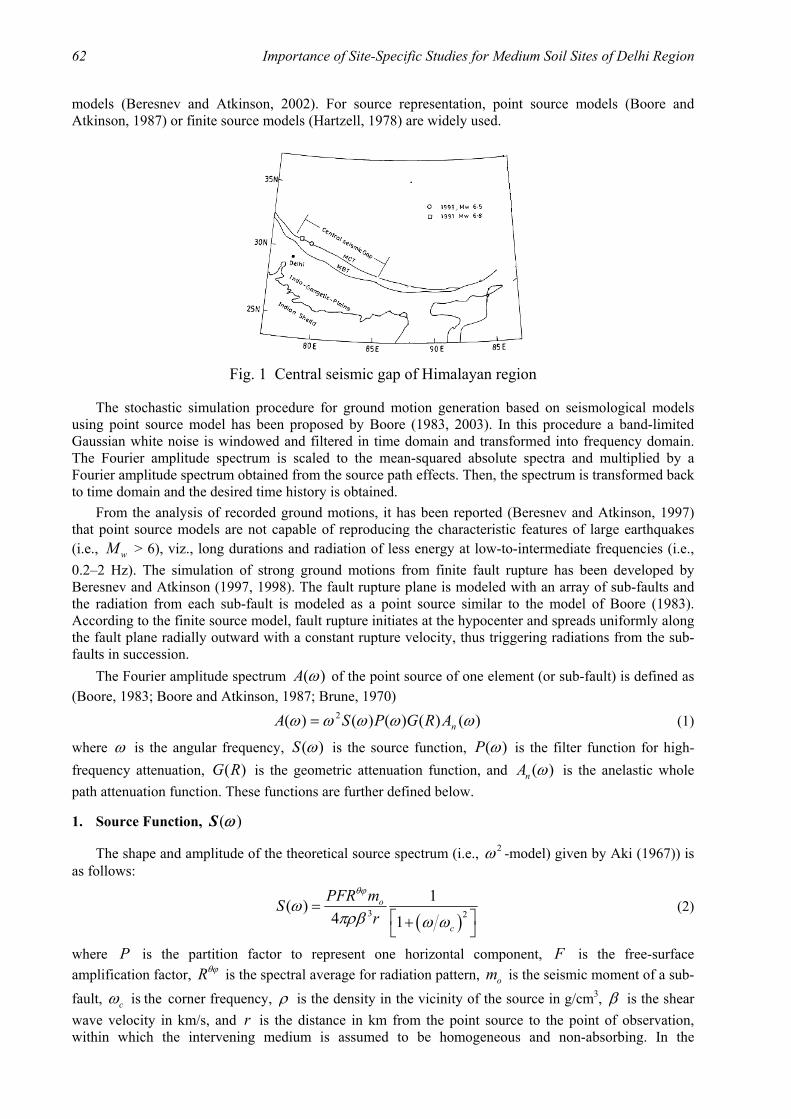
The importance of the effects of sediments above bedrock in modifying a strong ground motion has been long recognized (Boore, 2004; Boore and Joyner; 1997; Idriss and Seed, 1970; Seed and Idriss, 1969; Lam et al., 2001; Govindarajulu et al., 2004) in the literature. The nature of soil that changes the amplitude and frequency content of a ground motion has a major influence on the damaging effects of an earthquake. To account for these effects, most of the seismic codes, for example the Indian code (BIS, 2002), have defined response spectra for three types of soil, viz., hard soil, medium soil and soft soil. As an improvement over this approach, amplification factors based on empirical and theoretical data (Borcherdt, 1994) have been introduced in the International Building Code (ICC, 2000) for the site classes A to F, in the short-period and long-period ranges, based on the average shear wave velocity of the top 30 m soil stratum. It has been recommended that for the site class F (i.e., soft soil), additional site-specific studies be carried out. It has been also recommended (Heuze et al., 2004) that in addition to the use of seismic code provisions, analyses for the scenario earthquakes be carried out. For the Delhi region, seismologists (Bilham et al., 1998; Singh et al., 2002) have reported that three major thrust planes, viz., Main Central Thrust (MCT), Main Boundary Thrust (MBT), and Main Frontal Thrust (MFT) exist in Himalayas due to the relative movement of Indian plate by 5 cm/year with respect to the Eurasian plate. Khattri (1999) has estimated the probability of occurrence of a great earthquake of 8.5 moment magnitude from the large unbroken segment called central seismic gap (see Figure 1) between MBT and MCT in the next 100 years to be 0.59. Delhi is situated at a distance of roughly 200 km from MBT and 300 km from MCT. In this paper, site-specific studies have been carried out for three actual sites (of medium soil) at Delhi for which borelog details are available up to the rock. Rock outcropping motions have been generated for a reference site at the Delhi Ridge observatory, for the scenario earthquakes of moment magnitude wM = 7.5, 8.0 and 8.5 from central seismic gap of Himalayan region.
STRONG MOTION GENERATION
Recorded ground motions are not available for the Delhi region. Hence, in the present study artificial strong motions are generated using a stochastic model. Ground motions are generated by identifying the major fault zones and propagating seismic waves generated at these potential sources to the sites of interest. Path effects and anelastic attenuation effects are well predicted by the empirical and theoretical
62 Importance of Site-Specific Studies for Medium Soil Sites of Delhi Region
models (Beresnev and Atkinson, 2002). For source representation, point source models (Boore and Atkinson, 1987) or finite source models (Hartzell, 1978) are widely used.
Fig. 1 Central seismic gap of Himalayan region
The stochastic simulation procedure for ground motion generation based on seismological models using point source model has been proposed by Boore (1983, 2003). In this procedure a band-limited Gaussian white noise is windowed and filtered in time domain and transformed into frequency domain. The Fourier amplitude spectrum is scaled to the mean-squared absolute spectra and multiplied by a Fourier amplitude spectrum obtained from the source path effects. Then, the spectrum is transformed back to time domain and the desired time history is obtained. From the analysis of recorded ground motions, it has been reported (Beresnev and Atkinson, 1997) that point source models are not capable of reproducing the characteristic features of large earthquakes (i.e., wM > 6), viz., long durations and radiation of less energy at low-to-intermediate frequencies (i.e., 0.2–2 Hz). The simulation of strong ground motions from finite fault rupture has been developed by Beresnev and Atkinson (1997, 1998). The fault rupture plane is modeled with an array of sub-faults and the radiation from each sub-fault is modeled as a point source similar to the model of Boore (1983). According to the finite source model, fault rupture initiates at the hypocenter and spreads uniformly along the fault plane radially outward with a constant rupture velocity, thus triggering radiations from the sub-faults in succession. The Fourier amplitude spectrum ( )A ω of the point source of one element (or sub-fault) is defined as (Boore, 1983; Boore and Atkinson, 1987; Brune, 1970)
)()()()()( 2 ωωωωω nARGPSA = (1)
where ω is the angular frequency, ( )S ω is the source function, ( )P ω is the filter function for high-frequency attenuation, ( )G R is the geometric attenuation function, and ( )nA ω is the anelastic whole path attenuation function. These functions are further defined below.
1. Source Function, ( )S ω
The shape and amplitude of the theoretical source spectrum (i.e., 2ω -model) given by Aki (1967)) is as follows:
( )3 2
1( )4 1
= +
o
c
PFR mSr
θϕ
ωπρβ ω ω
(2)
where P is the partition factor to represent one horizontal component, F is the free-surface amplification factor, Rθϕ is the spectral average for radiation pattern, om is the seismic moment of a sub-
fault, cω is the corner frequency, ρ is the density in the vicinity of the source in g/cm3, β is the shear wave velocity in km/s, and r is the distance in km from the point source to the point of observation, within which the intervening medium is assumed to be homogeneous and non-absorbing. In the
ISET Journal of Earthquake Technology, June-December 2010 63
simulation of ground motion for the Delhi region in the present study, the values of different parameters are adopted (Singh et al., 2002) as P = 1 2 , F = 2.0, Rθϕ = 0.55, ρ = 2.85 gm/cc, r = 1.0 km, and β = 3.6 km/s.
The moment magnitude wM which defines the size of earthquake, is related (Hanks and Kanamori, 1979) to the seismic moment 0M of the earthquake as
00.67log 10.7wM M= − (3)
The rupture area A and sub-fault length l∆ corresponding to the moment magnitude of earthquake can be calculated from the empirical equations (Beresnev and Atkinson, 1998) as follows: log wA M= − 4.0 (4)
log l∆ = − 2 + 0.4 wM (5)
For a sub-fault of equal dimensions ( ,w l∆ = ∆ with w∆ and l∆ being the dimensions of the sub-fault), the seismic moment 0m of the sub-fault is given by
( )30m lσ= ∆ ∆ (6)
where σ∆ is the stress parameter (Beresnev and Atkinson, 1998). The number of sub-sources, subN , to be summed to reach the target seismic moment (i.e., 0M ) is given by
0sub
0
MNm
= (7)
The corner frequency cω that governs the acceleration amplitude and controls the frequency content of the earthquake at source is given by
2 r s
cy z
lβω =
∆ (8)
where ry is the constant representing the ratio of rupture velocity to the shear wave velocity of source, and sz is the parameter indicating the maximum rate of slip, also known as strength factor. The value of
ry is set equal to 0.8 by Beresnev and Atkinson (1997). The value of sz may vary from 0.5 to 2.0, and in the present study a value of 1.4 (Singh et al., 2002) has been adopted for the simulation of earthquake motions for the Delhi region.
2. Filter Function for High-Frequency Attenuation, ( )P ω
In order to account for high-frequency attenuation by the near-surface weathered layer, either a fourth-order Butterworth filter with the cut-off frequency max2=m fω π or a spectral decay parameter κ is widely used in stochastic models. In the present study, the Butterworth filter function ( )P ω with the cut-off frequency maxf = 15 Hz (Singh et al., 2002) is adopted:
( )1/28( ) 1−
= + mP ω ω ω (9)
3. Geometric Attenuation Factor, ( )G R
Geometric attenuation accounts for the decay and type of seismic waves. According to Singh et al. (2002) and Herrmann and Kijko (1983), for a distance of twice the crustal thickness body waves dominate (the direct seismic shear waves) and after that surface waves dominate (the reflected gL waves). Depending on the thickness of earth’s crust, trilinear or bilinear relationships are used for the calculation of ( ).G R The thickness of crust near Delhi has been reported to be 45–50 km (Tewari and Kumar (2003)) and hence following bilinear relationship is adopted in the present study:

64 Importance of Site-Specific Studies for Medium Soil Sites of Delhi Region
1( )G R RR
= < 100 km (10a)
1( )
100G R R
R= > 100 km (10b)
4. Anelastic Whole Path Attenuation Factor, ( )nA ω
The anelastic whole path attenuation factor ( )nA ω which represents wave energy loss due to the radiation damping of rocks is expressed as
2( )R
QnA e
ωβω
−= (11)
where Q is the quality factor. The Q factor depends on the wave transmission quality of rocks. For the Himalayan arc region, the Q factor has been estimated by Singh et al. (2002) from the available earthquake records as
48.0508)( ffQ = (12)
where f is the frequency in Hz.
5. Simulation of Time History
The Fourier amplitude spectrum derived above gives the frequency content of the earthquake ground motion. This frequency information is combined with random phase angles in a stochastic process to generate artificial ground motion (Boore, 1983) for each sub-fault. Simulations from all sub-faults are then lagged and summed to get the time history of earthquake. The duration of the sub-fault time window, wT , is represented as the sum of its source duration, sT , and distance-dependant duration, dT (Beresnev and Atkinson, 1997; Boore, 2003):
dsw TTT += (13)
Further, sT is taken as proportional to the inverse of the corner frequency (i.e., 1 cf ) and dT is taken as 0.05R (Beresnev and Atkinson, 1997; Boore, 2003). The finite fault simulation program (FINSIM) has been widely used for the generation of ground motions of large-size earthquakes (Atkinson and Beresnev, 2002; Beresnev and Atkinson, 1998; Roumelioti and Beresnev, 2003; Singh et al., 2002) and hence has been adopted in the present study.
ONE-DIMENSIONAL WAVE PROPAGATION: EQUIVALENT LINEAR ANALYSIS
The one-dimensional, equivalent linear, vertical wave propagation analysis is the widely used numerical procedure for modeling the soil amplification problems (Idriss, 1990; Yoshida et al., 2002). The equivalent linear analysis program SHAKE (Ordóñez, 2002; Schnabel et al., 1972) has been used in the present study. Since SHAKE is a total stress analysis program (Schnabel et al., 1972), the depth of water table has not been considered in the analysis.
TYPICAL SOIL STRATA FOR DELHI REGION
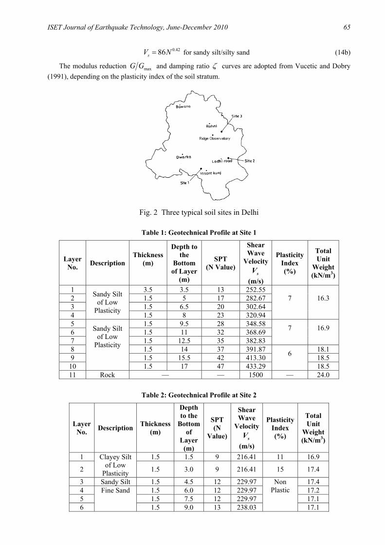
Three actual soil sites in Delhi, designated as Site 1, Site 2 and Site 3 (see Figure 2), are chosen for studying the building response. The layerwise soil characteristics (of the medium type soil) and the depth to the base of each layer from the surface are given in Tables 1–3. The measurements of shear wave velocity sV are not available for the sites chosen. However, the variations of N values with depth are available from the geotechnical data (see Tables 1–3). The variation of shear wave velocity with depth for the present study is obtained by using the correlations suggested for the Delhi region by Rao and Ramana (2004):
0.4379sV N= for sand (14a)
ISET Journal of Earthquake Technology, June-December 2010 65
0.4286sV N= for sandy silt/silty sand (14b)
The modulus reduction maxG G and damping ratio ζ curves are adopted from Vucetic and Dobry (1991), depending on the plasticity index of the soil stratum.
Fig. 2 Three typical soil sites in Delhi
Table 1: Geotechnical Profile at Site 1
Layer No. Description
Thickness (m)
Depth to the
Bottom of Layer
(m)
SPT (N Value)
Shear Wave
Velocity sV
(m/s)
Plasticity Index (%)
Total Unit
Weight (kN/m3)
1 3.5 3.5 13 252.55 2 1.5 5 17 282.67 3 1.5 6.5 20 302.64 4
Sandy Silt of Low
Plasticity 1.5 8 23 320.94
7
16.3
5 1.5 9.5 28 348.58 6 1.5 11 32 368.69 7 1.5 12.5 35 382.83
7
16.9
8 1.5 14 37 391.87 18.1 9 1.5 15.5 42 413.30 18.5
10
Sandy Silt of Low
Plasticity
1.5 17 47 433.29
6 18.5
11 Rock — — 1500 — 24.0
Table 2: Geotechnical Profile at Site 2
Layer No. Description Thickness
(m)
Depth to the
Bottom of
Layer (m)
SPT (N
Value)
Shear Wave
Velocity sV
(m/s)
Plasticity Index (%)
Total Unit
Weight (kN/m3)
1 1.5 1.5 9 216.41 11 16.9
2
Clayey Silt of Low
Plasticity 1.5 3.0 9 216.41 15 17.4
3 Sandy Silt 1.5 4.5 12 229.97 17.4 4 1.5 6.0 12 229.97 17.2 5 1.5 7.5 12 229.97 17.1 6
Fine Sand
1.5 9.0 13 238.03
Non Plastic
17.1
66 Importance of Site-Specific Studies for Medium Soil Sites of Delhi Region
7 1.5 10.5 15 253.13 17.1 8 1.5 12.0 19 280.21 17.1 9 1.5 13.5 20 286.46 17.7
10 1.5 15.0 21 292.54 17.7 11 1.5 16.5 26 320.68 17.7 12 1.5 18.0 31 363.81 17.7 13 1.5 19.5 41 409.14 17.7 14 1.5 21.0 41 409.14 6 19.8 15
Sandy Silt of Low
Plasticity 1.5 22.5 41 409.14 19.8
16 Rock - - 1500 - 24.0
Table 3: Geotechnical Profile at Site 3
Layer No. Description Thickness
(m)
Depth to the
Bottom of
Layer (m)
SPT (N
Value)
Shear Wave
Velocity sV
(m/s)
Plasticity Index (%)
Total Unit
Weight (kN/m3)
1 3.5 3.5 5 169.07 16.3 2 1.5 5.0 6 182.52 16.3 3 1.5 6.5 7 194.73 16.3 4 1.5 8.0 9 216.41 17.1 5 1.5 9.5 11 235.44 17.1 6 1.5 11.0 14 260.54 17.1 7 1.5 12.5 13 252.55 17.4 8
Sandy Silt
1.5 14.0 27 343.30
Non Plastic
17.4 9 1.5 15.5 36 387.39 15 17.7
10 1.5 17.0 32 368.69 15 17.7 11 1.5 18.5 13 252.55 15 17.7 12
Clayey Silt
1.5 20.0 28 348.58 15 17.7 13 1.5 21.5 45 425.45 18.1 14 1.5 23.0 28 348.58 18.1 15 1.5 24.5 42 413.30 18.1 16 1.5 26.0 44 421.45 18.5 17 1.5 27.5 47 433.29 18.5 18 1.5 29.0 444.70 18.5 19 1.5 30.5 444.70 19.8 20 1.5 32.0 444.70 19.8 21 1.5 33.5 444.70 19.8 22 1.5 35.0 444.70 19.8 23 1.5 36.5 444.70 19.8 24
Sandy Silt
1.5 38.0 444.70
Non Plastic
19.8 25 Rock -
> 50
1500 - 24.0
RESPONSE OF THREE SITES FOR SCENARIO EARTHQUAKES
The seismological parameters (see Table 4) used in the generation of rock outcrop motions for the Delhi region are broadly adopted from Singh et al. (2002). In order to minimize the noise due to random fault rupture in the simulation, 15 ground motions have been generated for each earthquake magnitude. One of these simulations of the time histories for rock outcrop (at Ridge Observatory) is compared (see Figure 3) with a simulation obtained by S.K. Singh (personal communication), for each of the magnitudes 7.5, 8.0 and 8.5.

ISET Journal of Earthquake Technology, June-December 2010 67
Table 4: Seismological Parameters for Strong-Motion Generation
Parameters wM = 7.5 wM = 8.0 wM = 8.5 Fault orientation Strike 300° Dip 7° Strike 300° Dip 7° Strike 300° Dip 7°
Fault dimension along strike and dip (km) 56×56 125×80 240×80 Depth of focus (km) 11 16 16 Stress parameter (bar) 50 50 50 No. of sub-faults 5×5 8×5 16×5 No. of sub-sources summed 28 57 339 Duration model 1 +cf 0.05R 1 +cf 0.05R 1 +cf 0.05R
Quality factor 508 0.48f 508 0.48f 508 0.48f Windowing function Saragoni-Hart Saragoni-Hart Saragoni-Hart
maxf (Hz) 15 15 15 Crustal shear wave velocity (km/s) 3.6 3.6 3.6 Crustal density (kN/m3) 2.8 2.8 2.8 Radiation strength factor 1.4 1.4 1.4
(a) (b)
(c)
Fig. 3 Comparisons of the simulations of rock outcrop motions from present study and Singh et al. (2002): (a) wM = 7.5; (b) wM = 8.0; and (c) wM = 8.5
68 Importance of Site-Specific Studies for Medium Soil Sites of Delhi Region
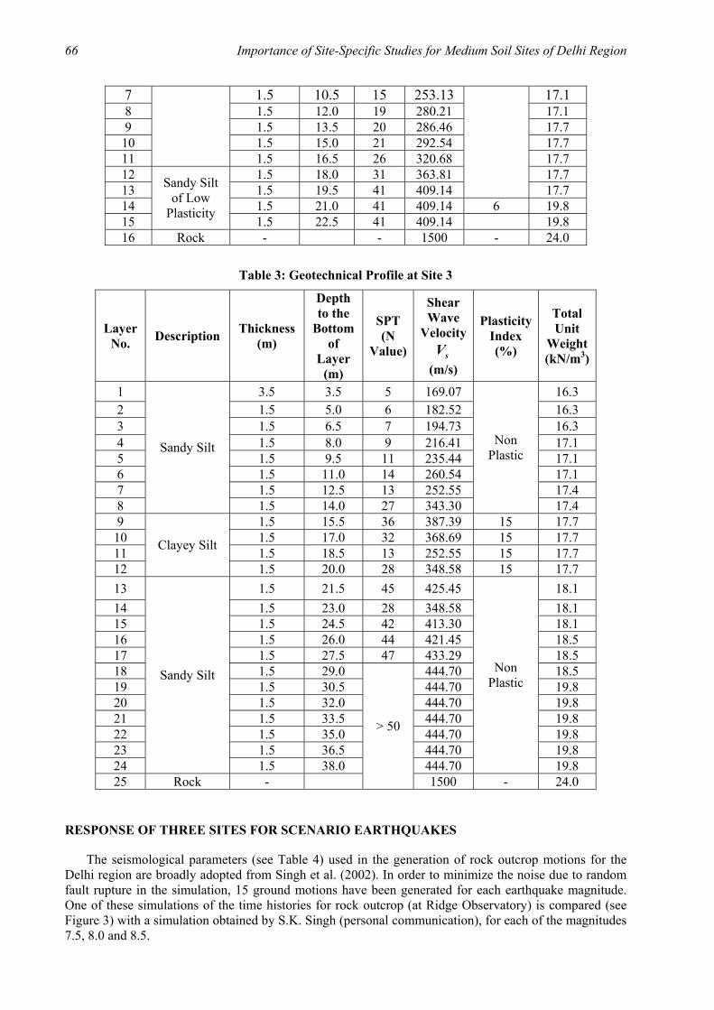
The rock outcrop motions simulated above are propagated through the soil strata of the three sites and the free-field motions are obtained. As a typical case, the bedrock level and free-field motions at the top of the three sites for one simulation in the case of wM = 7.5 are shown in Figure 4.
Fig. 4 Bedrock level and free-field motions at the top of three sites for a simulation of earthquake with wM = 7.5
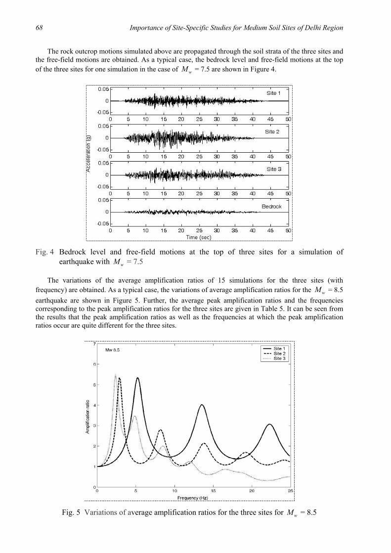
The variations of the average amplification ratios of 15 simulations for the three sites (with frequency) are obtained. As a typical case, the variations of average amplification ratios for the wM = 8.5 earthquake are shown in Figure 5. Further, the average peak amplification ratios and the frequencies corresponding to the peak amplification ratios for the three sites are given in Table 5. It can be seen from the results that the peak amplification ratios as well as the frequencies at which the peak amplification ratios occur are quite different for the three sites.
Fig. 5 Variations of average amplification ratios for the three sites for wM = 8.5
ISET Journal of Earthquake Technology, June-December 2010 69
Table 5: Average (over 15 Simulations) Fourier Amplification Ratios and Corresponding Frequencies for Site 1, Site 2 and Site 3
Fourier Amplification Ratio Frequency of Amplification (Hz) wM
Site 1 Site 2 Site 3 Site 1 Site 2 Site 3 7.5 5.7 6.5 6.0 5.5 3.25 2.625 8.0 5.6 6.2 5.8 5.375 3.25 2.625 8.5 5.3 5.3 5.5 5.25 2.87 2.375
The average ratios of the peak ground accelerations (PGAs) of free-field motions to the PGAs of bedrock motions for the three sites are shown in Table 6. Also shown in Table 6 are the average PGAs for the 15 simulations of bedrock motions and free-field motions for Site 1, Site 2 and Site 3. It can be observed that the PGA amplifications at the three sites are different for the three earthquake magnitudes.
Table 6: Average PGAs of Bedrock Motions, and Average PGAs of Free-Field Motions and Average PGA Amplification Ratios for Site 1, Site 2 and Site 3
Average PGA (cm/s2) Free-Field Motion
Average PGA Amplification RatiowM
Bedrock Motion Site 1 Site 2 Site 3 Site 1 Site 2 Site 3 7.5 15.74 31.73 51.73 39.60 2.02 3.29 2.52 8.0 23.36 53.48 53.10 60.10 2.29 2.27 2.57 8.5 46.47 100.82 100.01 113.32 2.17 2.15 2.44
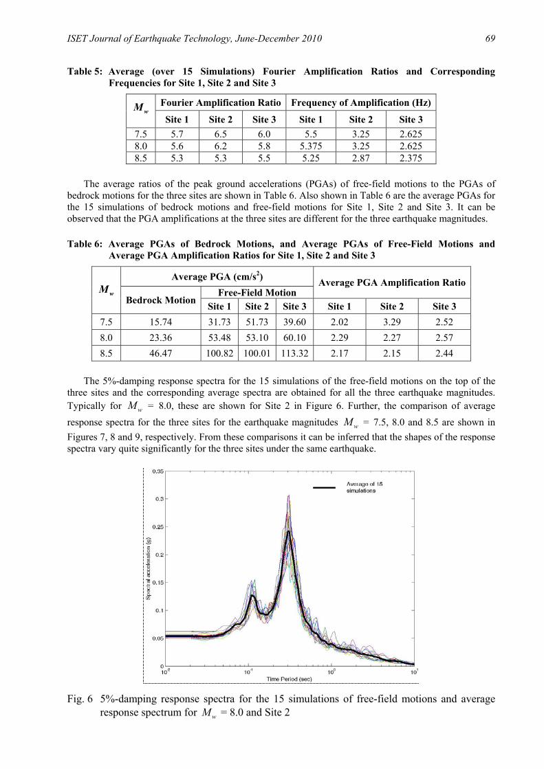
The 5%-damping response spectra for the 15 simulations of the free-field motions on the top of the three sites and the corresponding average spectra are obtained for all the three earthquake magnitudes. Typically for wM = 8.0, these are shown for Site 2 in Figure 6. Further, the comparison of average response spectra for the three sites for the earthquake magnitudes wM = 7.5, 8.0 and 8.5 are shown in Figures 7, 8 and 9, respectively. From these comparisons it can be inferred that the shapes of the response spectra vary quite significantly for the three sites under the same earthquake.
Fig. 6 5%-damping response spectra for the 15 simulations of free-field motions and average response spectrum for wM = 8.0 and Site 2

70 Importance of Site-Specific Studies for Medium Soil Sites of Delhi Region
Fig. 7 Comparison of average response spectra for Site 1, Site 2 and Site 3 and wM = 7.5
Fig. 8 Comparison of average response spectra for Site 1, Site 2 and Site 3 and wM = 8.0
Fig. 9 Comparison of average response spectra for Site 1, Site 2 and Site 3 and wM = 8.5
ISET Journal of Earthquake Technology, June-December 2010 71
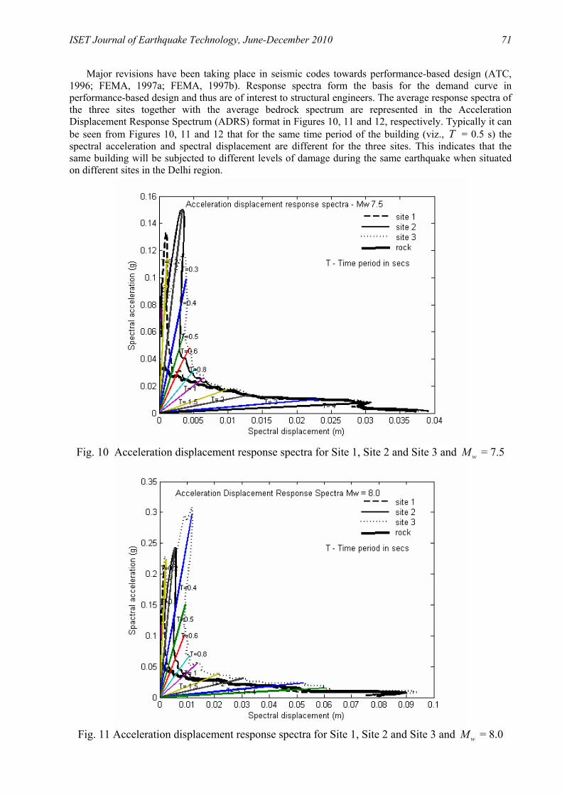
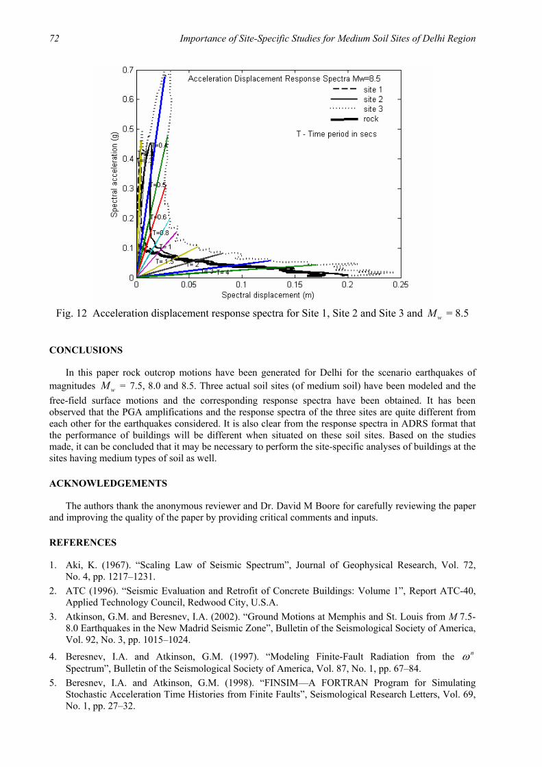
Major revisions have been taking place in seismic codes towards performance-based design (ATC, 1996; FEMA, 1997a; FEMA, 1997b). Response spectra form the basis for the demand curve in performance-based design and thus are of interest to structural engineers. The average response spectra of the three sites together with the average bedrock spectrum are represented in the Acceleration Displacement Response Spectrum (ADRS) format in Figures 10, 11 and 12, respectively. Typically it can be seen from Figures 10, 11 and 12 that for the same time period of the building (viz., T = 0.5 s) the spectral acceleration and spectral displacement are different for the three sites. This indicates that the same building will be subjected to different levels of damage during the same earthquake when situated on different sites in the Delhi region.
Fig. 10 Acceleration displacement response spectra for Site 1, Site 2 and Site 3 and wM = 7.5
Fig. 11 Acceleration displacement response spectra for Site 1, Site 2 and Site 3 and wM = 8.0
72 Importance of Site-Specific Studies for Medium Soil Sites of Delhi Region
Fig. 12 Acceleration displacement response spectra for Site 1, Site 2 and Site 3 and wM = 8.5
CONCLUSIONS
In this paper rock outcrop motions have been generated for Delhi for the scenario earthquakes of magnitudes wM = 7.5, 8.0 and 8.5. Three actual soil sites (of medium soil) have been modeled and the free-field surface motions and the corresponding response spectra have been obtained. It has been observed that the PGA amplifications and the response spectra of the three sites are quite different from each other for the earthquakes considered. It is also clear from the response spectra in ADRS format that the performance of buildings will be different when situated on these soil sites. Based on the studies made, it can be concluded that it may be necessary to perform the site-specific analyses of buildings at the sites having medium types of soil as well.
ACKNOWLEDGEMENTS
The authors thank the anonymous reviewer and Dr. David M Boore for carefully reviewing the paper and improving the quality of the paper by providing critical comments and inputs.
REFERENCES
1. Aki, K. (1967). “Scaling Law of Seismic Spectrum”, Journal of Geophysical Research, Vol. 72, No. 4, pp. 1217–1231.
2. ATC (1996). “Seismic Evaluation and Retrofit of Concrete Buildings: Volume 1”, Report ATC-40, Applied Technology Council, Redwood City, U.S.A.
3. Atkinson, G.M. and Beresnev, I.A. (2002). “Ground Motions at Memphis and St. Louis from M 7.5-8.0 Earthquakes in the New Madrid Seismic Zone”, Bulletin of the Seismological Society of America, Vol. 92, No. 3, pp. 1015–1024.
4. Beresnev, I.A. and Atkinson, G.M. (1997). “Modeling Finite-Fault Radiation from the nω Spectrum”, Bulletin of the Seismological Society of America, Vol. 87, No. 1, pp. 67–84.
5. Beresnev, I.A. and Atkinson, G.M. (1998). “FINSIM—A FORTRAN Program for Simulating Stochastic Acceleration Time Histories from Finite Faults”, Seismological Research Letters, Vol. 69, No. 1, pp. 27–32.

ISET Journal of Earthquake Technology, June-December 2010 73
6. Beresnev, I.A. and Atkinson, G.M. (2002). “Source Parameters of Earthquakes in Eastern and Western North America Based on Finite-Fault Modeling”, Bulletin of the Seismological Society of America, Vol. 92, No. 2, pp. 695–710.
7. Bilham, R., Blume, F., Bendick, R. and Gaur, V.K. (1998). “Geodetic Constraints on the Translation and Deformation of India: Implication for Future Great Himalayan Earthquakes”, Current Science, Vol. 74, No. 3, pp. 213–229.
8. BIS (2002). “IS 1893 (Part 1): 2002—Indian Standard Criteria for Earthquake Resistant Design of Structures, Part 1: General Provisions and Buildings (Fifth Revision)”, Bureau of Indian Standards, New Delhi.
9. Boore, D.M. (1983). “Stochastic Simulation of High-Frequency Ground Motions Based on Seismological Models of the Radiated Spectra”, Bulletin of the Seismological Society of America, Vol. 73, No. 6A, pp. 1865–1894.
10. Boore, D.M. (2003). “Simulation of Ground Motion Using the Stochastic Method”, Pure and Applied Geophysics, Vol. 160, No. 3-4, pp. 635–676.
11. Boore, D.M. (2004). “Can Site Response be Predicted?”, Journal of Earthquake Engineering, Vol. 8, No. S1, pp. 1–41.
12. Boore, D.M. and Atkinson, G.M. (1987). “Stochastic Prediction of Ground Motion and Spectral Response Parameters at Hard-Rock Sites in Eastern North America”, Bulletin of the Seismological Society of America, Vol. 77, No. 2, pp. 440–467.
13. Boore, D.M. and Joyner, W.B. (1997). “Site Amplifications for Generic Rock Sites”, Bulletin of the Seismological Society of America, Vol. 87, No. 2, pp. 327–341.
14. Borcherdt, R.D. (1994). “Estimates of Site-Dependent Response Spectra for Design (Methodology and Justification)”, Earthquake Spectra, Vol. 10, No. 4, pp. 617–653.
15. Brune, J. (1970). “Tectonic Stress and the Spectra of Seismic Shear Waves from Earthquakes”, Journal of Geophysical Research, Vol. 75, No. 26, pp. 4997–5009.
16. FEMA (1997a). “NEHRP Guidelines for the Seismic Rehabilitation of Buildings”, Report FEMA-273, Federal Emergency Management Agency, Washington, DC, U.S.A.
17. FEMA (1997b). “NEHRP Commentary on the Guidelines for the Seismic Rehabilitation of Buildings”, Report FEMA-274, Federal Emergency Management Agency, Washington, DC, U.S.A.
18. Govinda Raju, L., Ramana, G.V., Hanumantha Rao, C. and Sitharam, T.G. (2004). “Site-Specific Ground Response Analysis”, Current Science, Vol. 87, No. 10, pp. 1354–1362.
19. Hanks, T.C. and Kanamori, H. (1979). “A Moment Magnitude Scale”, Journal of Geophysical Research, Vol. 84, No. B5, pp. 2348–2350.
20. Hartzell, S.H. (1978). “Earthquake Aftershocks as Green’s Functions”, Geophysical Research Letters, Vol. 5, No. 1, pp. 1–4.
21. Herrmann, R.B. and Kijko, A. (1983). “Modeling Some Empirical Vertical Component gL Relations”, Bulletin of the Seismological Society of America, Vol. 73, No. 1, pp. 157–171.
22. Heuze, F., Archuleta, R., Bonilla, F., Day, S., Doroudian, M., Elgamal, A., Gonzales, S., Hoehler, M., Lai, T., Lavallee, D., Lawrence, B., Liu, P.-C., Martin, A., Matesic, L., Minster, B., Mellors, R., Oglesby, D., Park, S., Riemer, M., Steidl, J., Vernon, F., Vucetic, M., Wagoner, J. and Yang, Z. (2004). “Estimating Site-Specific Strong Earthquake Motions”, Soil Dynamics and Earthquake Engineering, Vol. 24, No. 3, pp. 199–223.
23. ICC (2000). “International Building Code”, International Code Council, Washington, DC, U.S.A. 24. Idriss, I.M. (1990). “Response of Soft Soil Sites during Earthquakes”, Proceedings of the H.B. Seed
Memorial Symposium, Berkeley, U.S.A., pp. 273–289. 25. Idriss, I.M. and Seed, H.B. (1970). “Seismic Response of Soil Deposits”, Journal of the Soil
Mechanics and Foundations Division, Proceedings of ASCE, Vol. 96, No. SM2, pp. 631–638. 26. Khattri, K.N. (1999). “An Evaluation of Earthquakes Hazard and Risk in Northern India”, Himalayan
Geology, Vol. 20, No. 1, pp. 1–46.

74 Importance of Site-Specific Studies for Medium Soil Sites of Delhi Region
27. Lam, N.T.K., Wilson, J.L. and Chandler, A.M. (2001). “Seismic Displacement Response Spectrum Estimated from the Frame Analogy Soil Amplification Model”, Engineering Structures, Vol. 23, No. 11, pp. 1437–1452.
28. Ordóñez, G.A. (2002). “SHAKE2000: A Computer Program for the I-D Analysis of Geotechnical Earthquake Engineering Problems—User’s Manual”, GeoMotions, LLC, Lacey, U.S.A.
29. Rao, H.Ch. and Ramana, G.V. (2004). “Correlation between Shear Wave Velocity and N value for Yamuna Sand of Delhi”, Proceedings of the International Conference on Geotechnical Engineering, Sharjah, U.A.E., pp. 262–268.
30. Roumelioti, Z. and Beresnev, I.A. (2003). “Stochastic Finite-Fault Modeling of Ground Motions from the 1999 Chi-Chi, Taiwan, Earthquake: Application to Rock and Soil Sites with Implications for Nonlinear Site Response”, Bulletin of the Seismological Society of America, Vol. 93, No. 4, pp. 1691–1702.
31. Schnabel, P.B., Lysmer, J. and Seed, H.B. (1972). “SHAKE: A Computer Program for Earthquake Response Analysis of Horizontally Layered Sites”, Report UCB/EERC-72/12, University of California, Berkeley, U.S.A.
32. Seed, H.B. and Idriss, I.M. (1969). “Influence of Soil Conditions on Ground Motions during Earthquakes”, Journal of the Soil Mechanics and Foundations Division, Proceedings of ASCE, Vol. 95, No. SM1, pp. 99–137.
33. Singh, S.K., Mohanty, W.K., Bansal, B.K. and Roonwal, G.S. (2002). “Ground Motion in Delhi from Future Large/Great Earthquakes in the Central Seismic Gap of the Himalayan Arc”, Bulletin of the Seismological Society of America, Vol. 92, No. 2, pp. 555–569.
34. Tewari, H.C. and Kumar, P. (2003). “Deep Seismic Sounding Studies and Its Tectonic Implications”, Journal of Virtual Explorer, Vol. 12, No. 1, pp. 30–54.
35. Vucetic, M. and Dobry, R. (1991). “Effect of Soil Plasticity on Cyclic Response”, Journal of Geotechnical Engineering, ASCE, Vol. 117, No. 1, pp. 89–107.
36. Yoshida, N., Kobayashi, S., Suetomi, I. and Miura, K. (2002). “Equivalent Linear Method Considering Frequency Dependent Characteristics of Stiffness and Damping”, Soil Dynamics and Earthquake Engineering, Vol. 22, No. 3, pp. 205–222.