Embed Size (px)
Citation preview
i
Implementing JobshopLean in a Maritime Foundry
Prepared for:
Best Manufacturing Practices Center of Excellence (BMPCOE) 4321 Hartwick Road, Suite 400
College Park, MD 20740 www.bmpcoe.org
Shahrukh A. Irani and Daniel Gallo Production Systems Analysts, llc
2654 Lane Road Upper Arlington, OH3220
August 31, 2009
2
Table of Contents
Section 1: Executive Summary
1.1 Introduction
1.2 Summary of Projects and Results Obtained
1.2.1 Manufacturing Cell for Improved Material Flow 1.2.2 Visual Management Communication System 1.2.3 Process Improvements in Inspection Department
1.3 Conclusions and Recommendations
Section 2: In-Depth Analysis and Discussion
2.1 Manufacturing Cell for Improved Material Flow
2.2 Visual Management Communication System
2.2.1 Visual Feedback in the Parking Lot 2.2.2 Visual Feedback in Weld Upgrade and Inspection Areas
2.2.3 Process Improvements in Inspection Department
2.3 Increase Throughput and Value-added Capacity Utilization 2.3.1 Magnetic Particle Inspection process and parallel operations 2.3.2 Analysis of Alternative Factory Flow/Layout Plans 2.3.3 Other Notes and Observations based on the PFAST Analysis Report
3
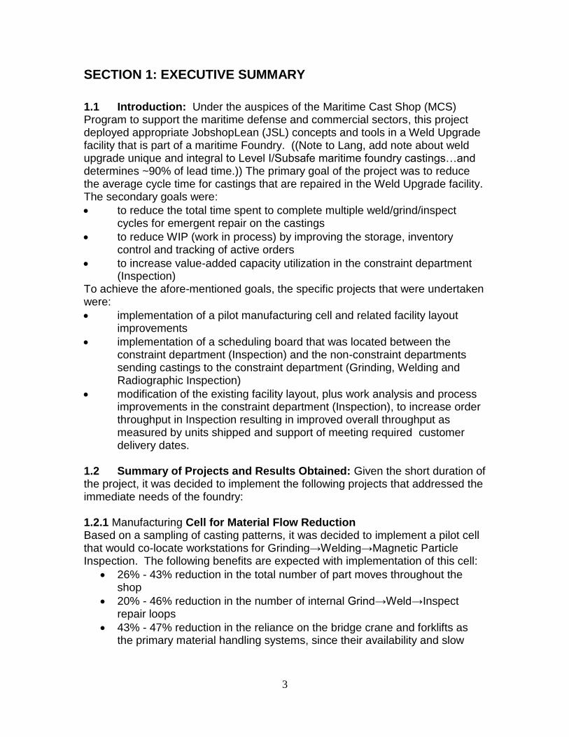
SECTION 1: EXECUTIVE SUMMARY
1.1 Introduction: Under the auspices of the Maritime Cast Shop (MCS) Program to support the maritime defense and commercial sectors, this project deployed appropriate JobshopLean (JSL) concepts and tools in a Weld Upgrade facility that is part of a maritime Foundry. ((Note to Lang, add note about weld upgrade unique and integral to Level I/Subsafe maritime foundry castings…and determines ~90% of lead time.)) The primary goal of the project was to reduce the average cycle time for castings that are repaired in the Weld Upgrade facility. The secondary goals were:
to reduce the total time spent to complete multiple weld/grind/inspect cycles for emergent repair on the castings
to reduce WIP (work in process) by improving the storage, inventory control and tracking of active orders
to increase value-added capacity utilization in the constraint department (Inspection)
To achieve the afore-mentioned goals, the specific projects that were undertaken were:
implementation of a pilot manufacturing cell and related facility layout improvements
implementation of a scheduling board that was located between the constraint department (Inspection) and the non-constraint departments sending castings to the constraint department (Grinding, Welding and Radiographic Inspection)
modification of the existing facility layout, plus work analysis and process improvements in the constraint department (Inspection), to increase order throughput in Inspection resulting in improved overall throughput as measured by units shipped and support of meeting required customer delivery dates.
1.2 Summary of Projects and Results Obtained: Given the short duration of the project, it was decided to implement the following projects that addressed the immediate needs of the foundry: 1.2.1 Manufacturing Cell for Material Flow Reduction Based on a sampling of casting patterns, it was decided to implement a pilot cell that would co-locate workstations for Grinding→Welding→Magnetic Particle Inspection. The following benefits are expected with implementation of this cell:
26% - 43% reduction in the total number of part moves throughout the shop
20% - 46% reduction in the number of internal Grind→Weld→Inspect repair loops
43% - 47% reduction in the reliance on the bridge crane and forklifts as the primary material handling systems, since their availability and slow
4
speed of operation contribute to operational inefficiencies, costs and delays
Due to the availability limitations of personnel in the Maritime Cast Shop who could commit time to additional projects, the implementation of the cell will be done in phases. Phase 1 is complete; additional phases are projected to be implemented in the next 6-12 months. 1.2.2 Visual Communication System (Scheduling Board) The Visual Communication System involves the use of 4 magnetic white boards and magnets to track the locations and completion status of active castings in the shop. The boards help to implement a DBR (Drum-Buffer-Rope) Pull scheduling system that would “choke” the flow of castings from Weld Upgrade into the queue of WIP (work-in-process) allowed to form in front of Inspection (which is the current bottleneck in the MCS). As this WIP queue decreases and capacity becomes available in Inspection, the boards give a visual signal that new work can be released into the MCS, or that the employees in the Grind and Weld departments can process new castings. Implementation of the Visual Management System will realize benefits such as a 50% increase in Line Of Sight between work centers, better ability to track/locate the progress of castings in real time, better ability to track shipment of castings on a weekly basis, more disciplined staging of work as per the daily schedule and better allocation of priorities to those castings that have emergent work detected in Inspection and must therefore return to Weld Upgrade for additional processing. 1.2.3 Process Improvements in Inspection Department Given that this department is the MCS system constraint, numerous improvement projects were suggested for implementation. In the short-term, the purchase of a second Magnetic Particle Inspection booth located in the Weld Upgrade department where the Layout Table is currently located would mitigate the problem of WIP build-up at Inspection. Based on analysis of the “From-To” chart, 56% of the total material flow in the MCS occurs between the rest of the facility and the Inspection department. Assuming that the current Magnetic Particle Inspection booth remains where it is, if the new Magnetic Particle Inspection booth were located in the Weld Upgrade department, it could reduce the traffic into the Inspection department from the rest of the facility by 10%-20%. 1.3 Conclusions and Recommendations:
MCS management must develop a more hands-on, metrics-driven, facts-based approach to decision-making and project justification.
MCS management must invest in training of employees and managers, especially in Weld Upgrade and Inspection, in problem-solving, process improvement, self-inspection of quality of work, etc.
Implementation of the pilot cell for repairing small castings must be completed subject to the following requirements: Requirement #1: Significant and sustained effort must be made to obtain
employee buy-in ex. employees in the Grinding and Welding departments could be invited to meet each other during a town hall meeting to form
5
Welder+Grinder pairs who would volunteer to work in the pilot cell being implemented
In order to better organize product flow and to get shipping functions clear of inspection functions consider Investing in construction to extend the existing building in the area of shipping. This would move the Shipping department out of the Inspection department to better separate and organize parts flow. If it is decided to extend the building to create a separate Shipping area, the current area that is being used as a Receiving/Shipping area could possibly be used to locate the new Magnetic Particle Inspection booth adjacent to the existing one. See discussion in section 2.3.
The second Magnetic Particle Inspection booth should be installed in the Weld Upgrade department where the Layout Table is currently located subject to the following requirements: Requirement #1: MCS management must do some analysis to ensure
that, if one or both of the two bridge cranes currently being used for parts handling in the Weld Upgrade department are also going to be used for local parts handling in this booth, that this does not exacerbate the current delays due to non-availability of the cranes
Requirement #2: MCS management should purchase sturdy metal pallets that, in combination with a powered heavy-load bearing pallet truck, could be used to transport some of the castings, whereby there would be less demand on the bridge cranes to move the castings (since the extensive use of the bridge cranes for both loading/unloading castings in the Grinding and Welding booths, as well as transportation up and down the length of the Weld Upgrade department is creating congestion and waiting delays)
Requirement #3: If the pallet truck (or trucks) does get purchased, MCS management should encourage employees in the Weld Upgrade department to utilize the bridge cranes primarily for (i) loading/unloading castings in the Grinding and Welding booths and (ii) transporting the castings between the Grinding and Welding booths. Pallet truck or other floor mounted mobile devices for lineal travel would lower crane usage and associated waiting for cranes.
Requirement #4: A significant number of the castings that visit the Magnetic Particle Inspection booth also visit the Dimensional/Visual Inspection tables; therefore, MCS management should conduct additional analyses to verify this and appropriately explore the feasibility of co-locating Dimensional/VT capability in or adjacent to this MT booth that will be located inside the Weld Upgrade department
Invest in facility layout changes inside the existing building to speed up the material flow and rework loops between the Grinding, Welding and Inspection departments Requirement #1: Shift the grinding booths to abut the welding booths so
that multiple Grind→Weld “modules” (partial cells) can be implemented Requirement #2: Develop a Group Technology (GT) classification and
coding system to explore the possibility that additional families of castings exist, since that would support the creation of Grind→Weld “modules”
6
(partial cells); each module could be dedicated to a certain family of castings
i. This analysis could be done by developing a GT system utilizing pre-existing systems described in the literature ex. Small vs. Large, Ferrous vs. Non-Ferrous, Outside Grinding Only vs. Outside and Inside Grinding, etc.
ii. MCS offered an excellent “first pass” on potential families ex. Military (Large pieces – casings, pumps, valves, long lead times), Military (Small pieces – impellers, smaller assembly parts, short lead times), Hot List/Expedited Orders (Miscellaneous, no clear-cut processing or setup/tooling families), ASME Orders (Large vs. Small), Unusual Orders (Fabrications), Commercial/Regal, Ferrous/Non-Ferrous
Requirement #3: Partially “dissolve” the wall that separates the Welding Upgrade and Inspection departments by re-opening the access “hole” near the Layout Table that has been walled up. Refer to section 2.3.
Requirement #4: Completely “dissolve” the wall that separates the Welding Upgrade and Inspection departments by relocating the welding equipment into the welding booths and installing load-bearing columns to carry the wiring, air lines, etc. Refer to section 2.3.
Increase the value-added utilization of labor and equipment in the Inspection department subject to the following requirements: Requirement #1: MCS management should enroll the Manager and
Foreman of this department in formal TOC (Theory Of Constraints) and Lean classes that provide training on Process Improvement, Setup Reduction, Problem Solving, etc.
Requirement #2: Assuming that the wall separating the Weld Upgrade and Inspection department is “dissolved”, the layout of this department could be completely re-designed to support streamlined flow with weld upgrade areas.
Requirement #3: Either the second bridge crane should be installed or, as was proposed for the Weld Upgrade department, sturdy metal pallets could be purchased that, in combination with a powered heavy-load bearing pallet truck, could be used to transport some of the heavy castings; thereby, due to the reduced utilization achieved by this “right-sizing” of the material handling equipment, the single bridge crane currently in use ceases being a bottleneck which employees must wait for.
Requirement #4: MCS management should consider recruiting an IE student intern from The Ohio State University, Penn State or UPitt to conduct Work Study/Methods Analysis to reduce non-value added work elements that reduce productivity and efficiency in the department
Ensure that MCS progresses from the current Hot List/Expedite mode to Finite Capacity Scheduling using ProfitKey or other appropriate system. Requirement #1: MCS should list the core requirements they would want
their scheduling system to meet. Once this is done they should confirm that ProfitKey or any alternatives that might be considered meet these needs.
7
Requirement#2: MCS management should ensure that the Foremen of the Weld Upgrade and Inspection departments engage in co-operative efforts to learn to use the manual scheduling board that has been installed as a short-term stop-gap measure to ensure that the Weld Upgrade department does not exceed established limits on how much WIP (work in process) is allowed to queue up before the Inspection department, which is the current bottleneck at the MCS/foundry
Requirement #3: MCS management should ensure that personnel who will be responsible for working with and executing the schedules produced by ProfitKey have sufficient training in production planning and control, Finite Capacity Scheduling, etc.
Requirement #4: MCS management should consider contacting the following person – George Rogers (Ph: 716-897-2288) – since they have successfully used their ERP system, E2 (from ShopTech Corporation), to track jobs in their small jobshop (Kehr-Buffalo Wire Frame Co. Inc, www.kbwf.net)
Given that MCS managers are under considerable pressure to clear the existing backlog of orders, if they were to choose a subset of the above projects to be on their “must do” list, then the pilot cell, installation of the new Magnetic Particle Inspection booth and use of the scheduling boards should be their immediate priority.
SECTION 2: IN-DEPTH ANALYSIS AND DISCUSSION:
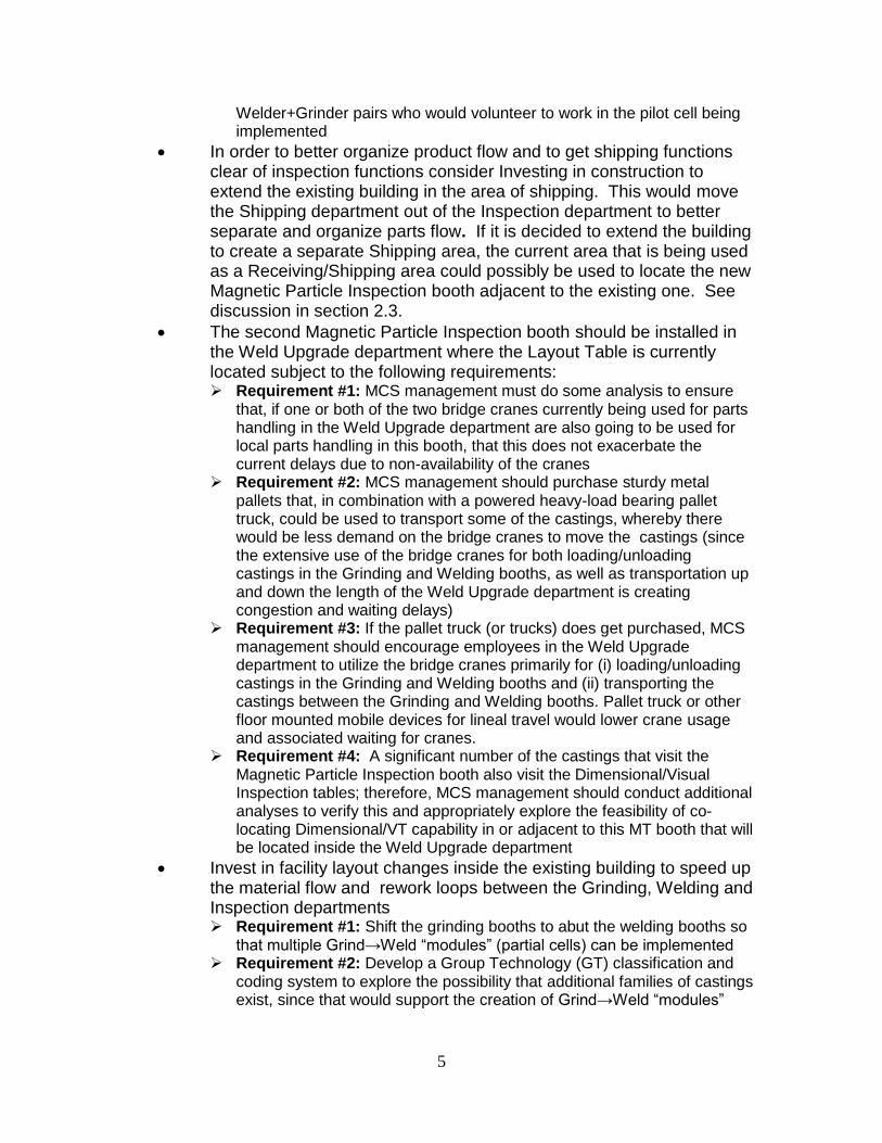
2.1 Manufacturing Cell for Material Flow Reduction: Observation: Figure 2.1 shows the Spaghetti Diagram for the routing of a single representative casting. Currently, the casting must be moved a total of 270 times to complete all the operations listed in its work traveller. Due to its size and weight, the only material handling equipment capable of moving this casting are the overhead bridge cranes in the Weld Upgrade and Inspection departments, and the forklifts. Figure 2.1
8
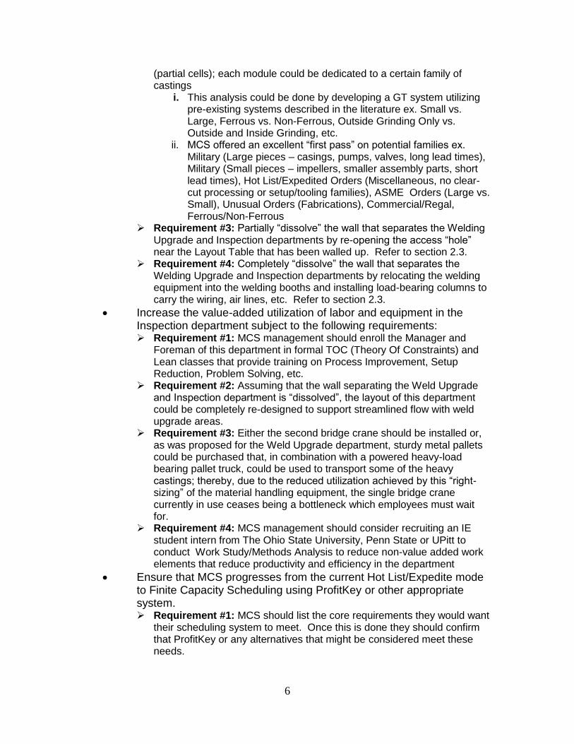
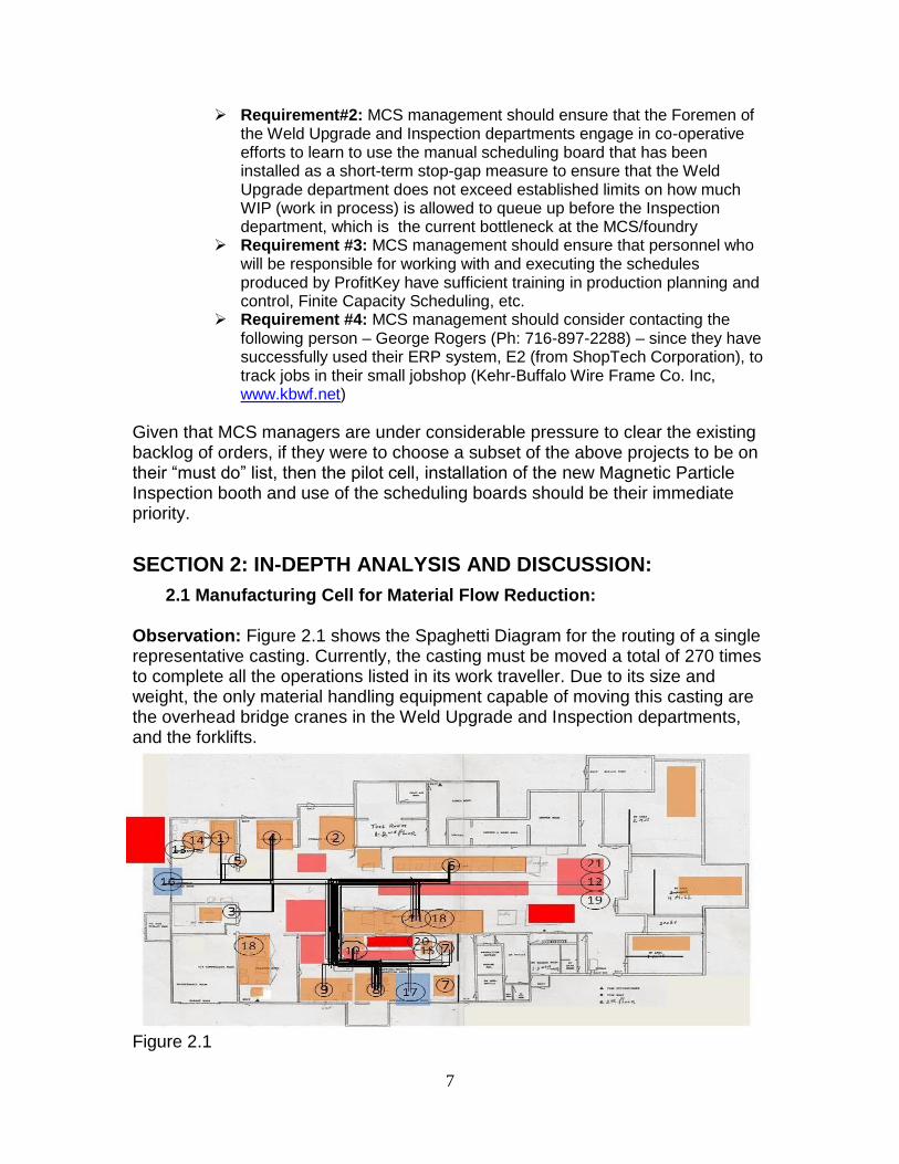
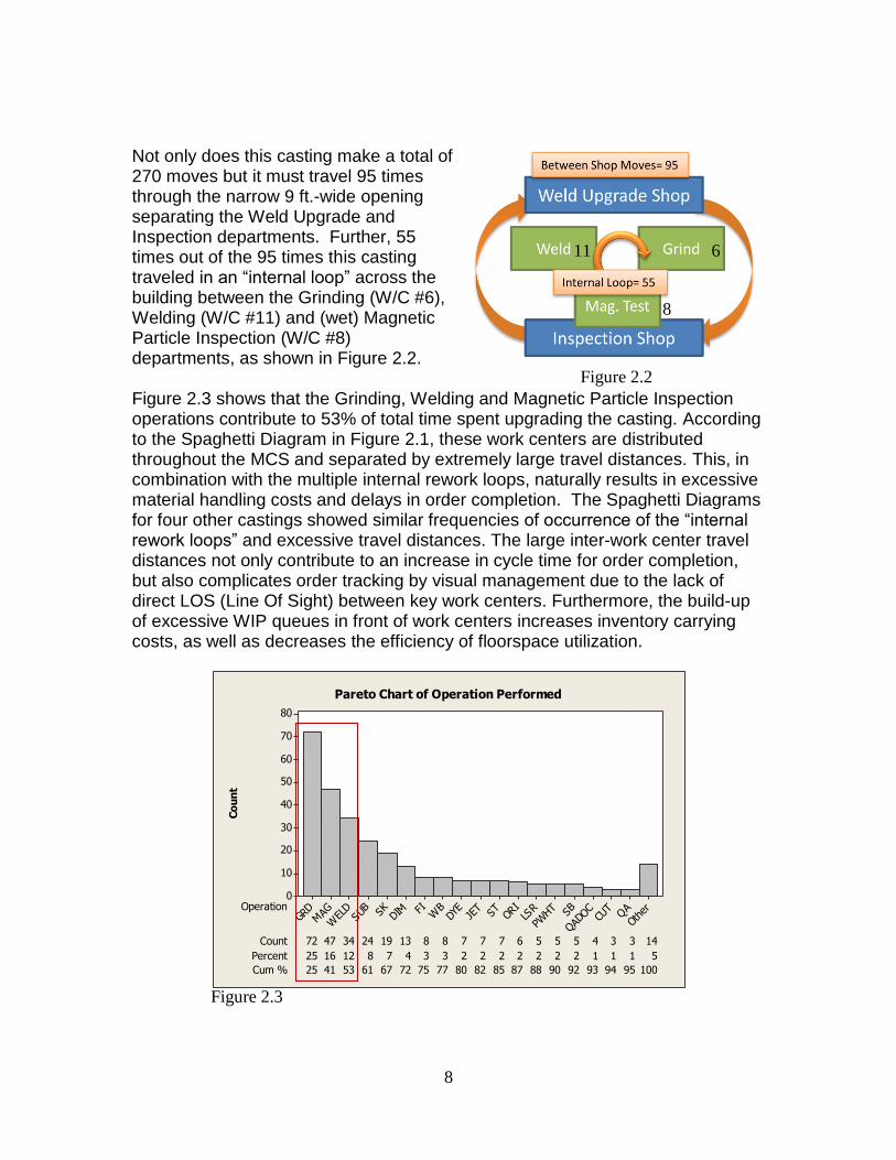
Not only does this casting make a total of 270 moves but it must travel 95 times through the narrow 9 ft.-wide opening separating the Weld Upgrade and Inspection departments. Further, 55 times out of the 95 times this casting traveled in an “internal loop” across the building between the Grinding (W/C #6), Welding (W/C #11) and (wet) Magnetic Particle Inspection (W/C #8) departments, as shown in Figure 2.2. Figure 2.3 shows that the Grinding, Welding and Magnetic Particle Inspection operations contribute to 53% of total time spent upgrading the casting. According to the Spaghetti Diagram in Figure 2.1, these work centers are distributed throughout the MCS and separated by extremely large travel distances. This, in combination with the multiple internal rework loops, naturally results in excessive material handling costs and delays in order completion. The Spaghetti Diagrams for four other castings showed similar frequencies of occurrence of the “internal rework loops” and excessive travel distances. The large inter-work center travel distances not only contribute to an increase in cycle time for order completion, but also complicates order tracking by visual management due to the lack of direct LOS (Line Of Sight) between key work centers. Furthermore, the build-up of excessive WIP queues in front of work centers increases inventory carrying costs, as well as decreases the efficiency of floorspace utilization.
Co
un
t
Operation
Count 7 7 7 6 5 5 5 4 3 372 14
Percent 25 16 12 8 7 4 3 3
47
2 2 2 2 2 2 2 1 1 1
34
5
Cum % 25 41 53 61 67 72 75 77
24
80 82 85 87 88 90 92 93 94 95
19
100
13 8 8
Othe
rQA
CUT
QADOCSB
PWHTLS
ROR
ISTJE
TDY
EW
BFIDI
MSKSUB
WEL
DMAGGR
D
80
70
60
50
40
30
20
10
0
Pareto Chart of Operation Performed
Figure 2.2
6 11
8
Figure 2.3
9
Recommendation: To combat the issues discussed above, a pilot work cell was recommended that co-locates Grinding, Welding and Magnetic Particle Inspection. The cell would co-locate multiple consecutive operations in the routings of many castings in a single work area that would be shared by several cross-trained employees who would be provided all the necessary resources to process that family of castings. By combining operations in one work area, reducing the inter-operation travel distances, and allowing quick feedback between operators on quality-related issues, this cell delivers significant performance benefits. The MCS is investing considerable effort to change the culture of their employees and cross-train them to work in a cellular workspace. Two paradigms were examined for setting up the cell:
A) Dedicate each side of the cell separate welding and grinding areas:
Each side of the cell can be dedicated to be either a weld area or grind area. For either operation, the layout for each area can be optimized for ease of use. The hand-held Magnetic Particle Inspection unit is portable, so the inspection operation can be done on either side of the cell. The major concern for this approach is that parts still need to be moved from the dedicated grind area to the dedicated weld area and vice-versa. However, the worker/s in either area will not have to move their tools and equipment to the other side of the cell. This leads to the question: Should we move the parts or move the workers? For example, when the grinder finishes Part #1, he will have to wait for the welder to finish Part #2 before Part #1 can be transferred from the grind area to the weld area in the cell. In essence, this would tie up both work areas because the cell is designed with grinding and welding in separate areas. However, the grinder could be working on the next part, Part #3, and put the finished Part #1 in the welders queue. If the grinder can complete 2 parts before the welder completes 1, the cell will not be balanced. Therefore, this approach will work best if the process times for grinding and welding are relatively equal.
B) Perform grinding/welding/inspection as needed in same location
without disrupting part set-up:
The alternative to Option (A), as described above, was to have two flexible work areas able to support the weld/ grind and inspection operations using quick changeover fixtures, redundant, or easily moveable tool setups. The two work areas would be a mirror image of one another with easy access to weld machine, grinding station tools and sharing of the hand-held Magnetic Particle Inspection unit. The part would always stay fixtured on the work table, possibly re-oriented if needed, and have all three operations done on it without removing it from the work table. This would eliminate numerous internal rework loops that the typical part needs as it travels between Welding, Grinding and Inspection departments.
10
The question this raises is;would it better to have the cell operators move within the cell and leave the part set up, or fix the location where each cell operator works but move the parts between their locations? A potential downfall of the option B (part stays fixed) approach is that the part will spend more time inside the cell and there will be a critical need to clarify and define the work and other responsibilities, of the cross-trained workers in the cell. However, if multiple operations are completed while the casting is set up, it will force parts to be worked further toward completion once the part enters the cell. Since the hand-held Magnetic Particle Inspection may not count as a certified inspection, the part will ultimately have to be moved to the main Inspection area so that the formal inspection can be done in the Wet Magnetic Particle Inspection booth in that department.
Either option reduces the number of castings that have to travel large distances
when they are processed in the main Inspection department, which “elevates the
capacity constraint” in that department, reduces the number of internal work
loops and maximizes the usage flexibility of the work areas.
The physical creation of a work cell can be a time-consuming and expensive endeavor if the proper personnel are not assigned to the task and sufficient resources are not committed. In order to reduce risk, maximize lessons learned, and limit initial investment required, it has been recommended that the cell be completed in phases. Phase 1 of the work cell has been completed.. Phase 2 and 3 are expected to follow at a future date. Activities in Phase 1(Completed):
Demolish and clean the area where the work cell will be installed in order to support future phases of the implementation effort
o Decide proper welding machine capability to install in the work cell. o Remove wall separating two existing work centers. o Re-layout electrical shut-off switches, air lines, gas lines, etc. to
comply with OSHA regulations and support the new cell layout.
New construction to be done in the work cell o Provide adequate storage and space to support all three operations
(Grinding, Welding and Inspection) to be done in the cell. o Cut 4’x6’ welding table in half to allow 360 degrees of access. o Re-weld legs on table. o Install new weld tables into cell.
o Install a flexible curtain between new work areas. o Move air lines and drain water from air lines
o Modify and install overhead air ventilation for both work areas
o Install welders in both work areas.
o Install grinding equipment in both work areas.
11
Storage
Electric Box
Water Test Area
StorageLockers
Storage
o Install swinging curtain gates in both work areas.
o Install mini-boards in both work areas to facilitate visual
communication.
o Install protection for water coolant mix pipe.
Reconfigure the cell, select and cross-train workers selected to work in the
cell
o Bring in welders and grinders to arrange tools and layout the
workspace as per their desires and standards
o Train the welders and grinders to use the hand-held yoke for
Magnetic Particle Inspection.
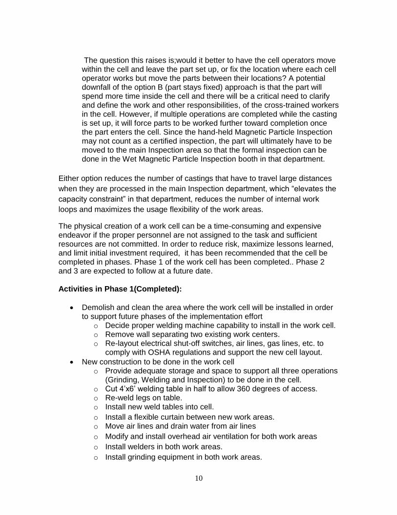
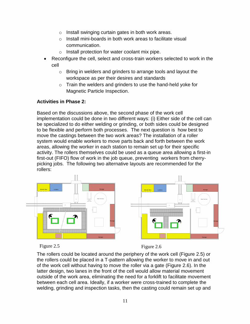
Activities in Phase 2: Based on the discussions above, the second phase of the work cell implementation could be done in two different ways: (i) Either side of the cell can be specialized to do either welding or grinding, or both sides could be designed to be flexible and perform both processes. The next question is how best to move the castings between the two work areas? The installation of a roller system would enable workers to move parts back and forth between the work areas, allowing the worker in each station to remain set up for their specific activity. The rollers themselves could be used as a queue area allowing a first-in first-out (FIFO) flow of work in the job queue, preventing workers from cherry-picking jobs. The following two alternative layouts are recommended for the rollers: The rollers could be located around the periphery of the work cell (Figure 2.5) or the rollers could be placed in a T-pattern allowing the worker to move in and out of the work cell without having to move the roller via a gate (Figure 2.6). In the latter design, two lanes in the front of the cell would allow material movement outside of the work area, eliminating the need for a forklift to facilitate movement between each cell area. Ideally, if a worker were cross-trained to complete the welding, grinding and inspection tasks, then the casting could remain set up and
Storage
Electric Box
Water Test Area
StorageLockers
Storage
Figure 2.5 Figure 2.6
12
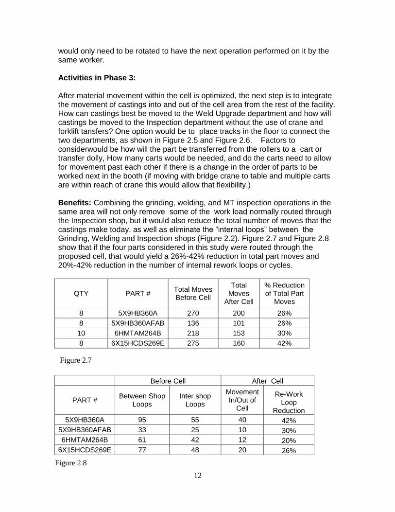
would only need to be rotated to have the next operation performed on it by the same worker. Activities in Phase 3: After material movement within the cell is optimized, the next step is to integrate the movement of castings into and out of the cell area from the rest of the facility. How can castings best be moved to the Weld Upgrade department and how will castings be moved to the Inspection department without the use of crane and forklift tansfers? One option would be to place tracks in the floor to connect the two departments, as shown in Figure 2.5 and Figure 2.6. Factors to considerwould be how will the part be transferred from the rollers to a cart or transfer dolly, How many carts would be needed, and do the carts need to allow for movement past each other if there is a change in the order of parts to be worked next in the booth (if moving with bridge crane to table and multiple carts are within reach of crane this would allow that flexibility.) Benefits: Combining the grinding, welding, and MT inspection operations in the same area will not only remove some of the work load normally routed through the Inspection shop, but it would also reduce the total number of moves that the castings make today, as well as eliminate the “internal loops” between the Grinding, Welding and Inspection shops (Figure 2.2). Figure 2.7 and Figure 2.8 show that if the four parts considered in this study were routed through the proposed cell, that would yield a 26%-42% reduction in total part moves and 20%-42% reduction in the number of internal rework loops or cycles.
QTY PART # Total Moves Before Cell
Total Moves
After Cell
% Reduction of Total Part
Moves
8 5X9HB360A 270 200 26%
8 5X9HB360AFAB 136 101 26%
10 6HMTAM264B 218 153 30%
8 6X15HCDS269E 275 160 42%
Before Cell After Cell
PART # Between Shop
Loops Inter shop
Loops
Movement In/Out of
Cell
Re-Work Loop
Reduction
5X9HB360A 95 55 40 42%
5X9HB360AFAB 33 25 10 30%
6HMTAM264B 61 42 12 20%
6X15HCDS269E 77 48 20 26%
Figure 2.7
Figure 2.8
13
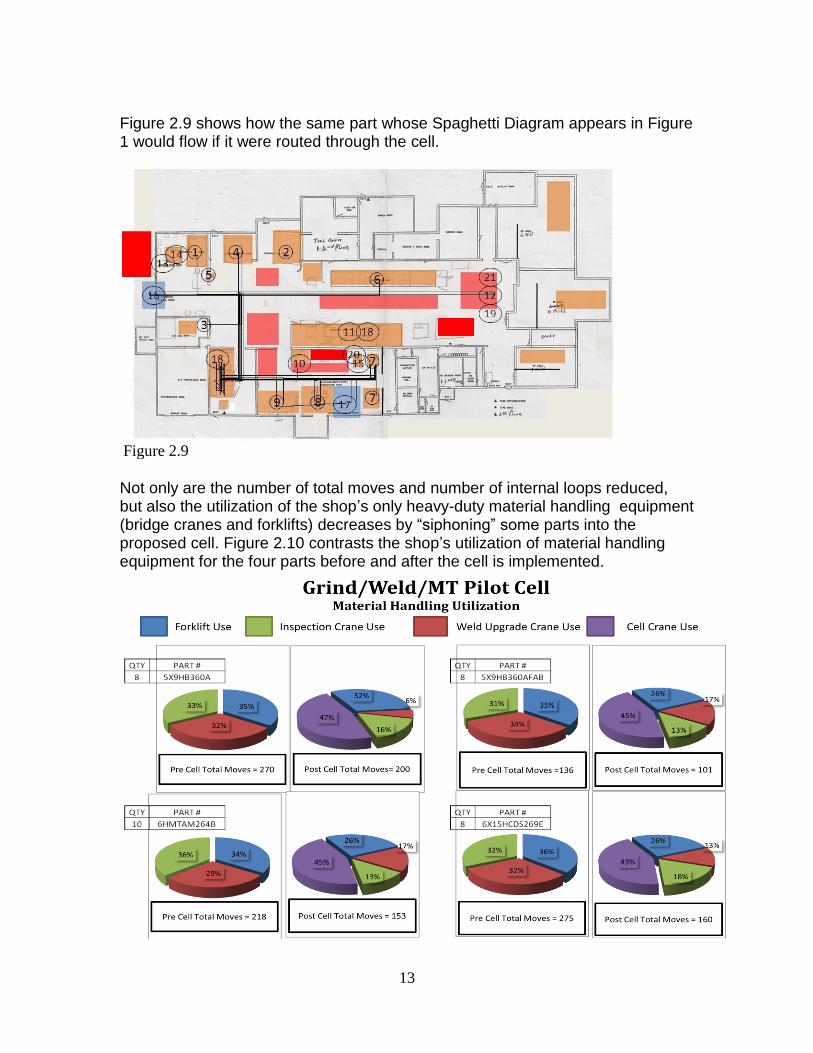
Figure 2.9 shows how the same part whose Spaghetti Diagram appears in Figure 1 would flow if it were routed through the cell.
Not only are the number of total moves and number of internal loops reduced, but also the utilization of the shop’s only heavy-duty material handling equipment (bridge cranes and forklifts) decreases by “siphoning” some parts into the proposed cell. Figure 2.10 contrasts the shop’s utilization of material handling equipment for the four parts before and after the cell is implemented.
Figure 2.9
14
Considering all four part numbers, the overhead crane in the cell would account for 43%-47% of part moves for those castings.
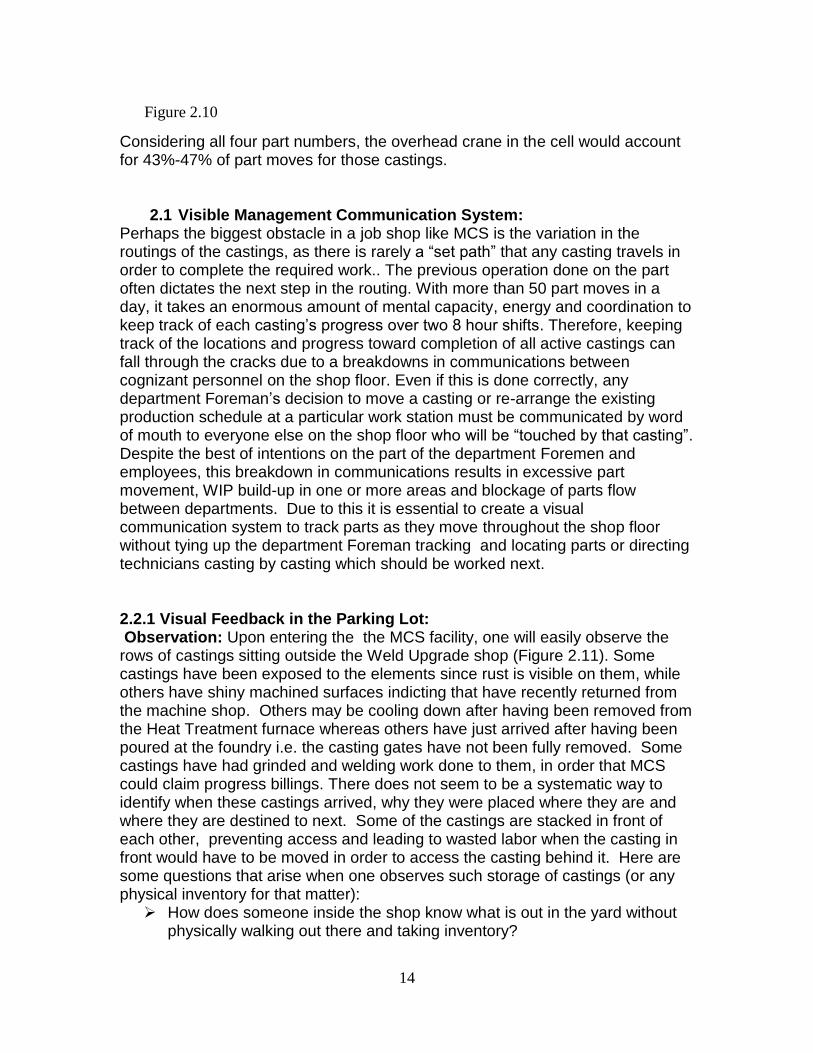
2.1 Visible Management Communication System: Perhaps the biggest obstacle in a job shop like MCS is the variation in the routings of the castings, as there is rarely a “set path” that any casting travels in order to complete the required work.. The previous operation done on the part often dictates the next step in the routing. With more than 50 part moves in a day, it takes an enormous amount of mental capacity, energy and coordination to keep track of each casting’s progress over two 8 hour shifts. Therefore, keeping track of the locations and progress toward completion of all active castings can fall through the cracks due to a breakdowns in communications between cognizant personnel on the shop floor. Even if this is done correctly, any department Foreman’s decision to move a casting or re-arrange the existing production schedule at a particular work station must be communicated by word of mouth to everyone else on the shop floor who will be “touched by that casting”. Despite the best of intentions on the part of the department Foremen and employees, this breakdown in communications results in excessive part movement, WIP build-up in one or more areas and blockage of parts flow between departments. Due to this it is essential to create a visual communication system to track parts as they move throughout the shop floor without tying up the department Foreman tracking and locating parts or directing technicians casting by casting which should be worked next. 2.2.1 Visual Feedback in the Parking Lot: Observation: Upon entering the the MCS facility, one will easily observe the rows of castings sitting outside the Weld Upgrade shop (Figure 2.11). Some castings have been exposed to the elements since rust is visible on them, while others have shiny machined surfaces indicting that have recently returned from the machine shop. Others may be cooling down after having been removed from the Heat Treatment furnace whereas others have just arrived after having been poured at the foundry i.e. the casting gates have not been fully removed. Some castings have had grinded and welding work done to them, in order that MCS could claim progress billings. There does not seem to be a systematic way to identify when these castings arrived, why they were placed where they are and where they are destined to next. Some of the castings are stacked in front of each other, preventing access and leading to wasted labor when the casting in front would have to be moved in order to access the casting behind it. Here are some questions that arise when one observes such storage of castings (or any physical inventory for that matter):
How does someone inside the shop know what is out in the yard without physically walking out there and taking inventory?
Figure 2.10
15
Which parts have been brought in from the foundry to be released into the shop?
Which parts are left outside to cool after being removed from the Heat Treatment furnace?
Which parts are on-hold waiting for government disposition? Which parts are to be scrapped?
Recommendation: For each part in the area, write a brief statement as to why this casting is currently being stored in this area. Repeat this exercise periodically every few weeks to get a good mix of castings that come through. Use an Affinity Diagram to group similar reasons together i.e. this casting is on-hold waiting for government approval or this casting recently arrived from the foundry, etc. Think of these groupings as buckets, each bucket should be specific needs based on the statements. Once the needs for this area have been established, create designated areas for each grouping per the Affinity Diagram. The areas can be as simple as a spray painted box on the lot establishing boundaries or as complex as an outdoor vertical shelving system. The design of this storage area (or shelving system) should allow access to all parts from all sides. To protect machined castings or castings that have had previous work done on them, the castings could be wrapped in plastic or put inside environment-proof boxes ex. a crate wrapped in plastic. Once the areas have been established, they should be clearly marked in order to visually communicate the availability of free space, the on-hand inventory of castings by type currently in this area and how long any casting has been held n the area. This information can be tracked on a board inside the shop to prevent the “piling up” of excessive WIP of these castings in this area. Benefits: By providing immediate visual feedback, this will reduce the need for material handlers, department Foremen and office workers expending time looking for parts. This will not only improve the organization of the area, but also allow documentation as to how the shop is running at the present current time.
Figure 2.11
16
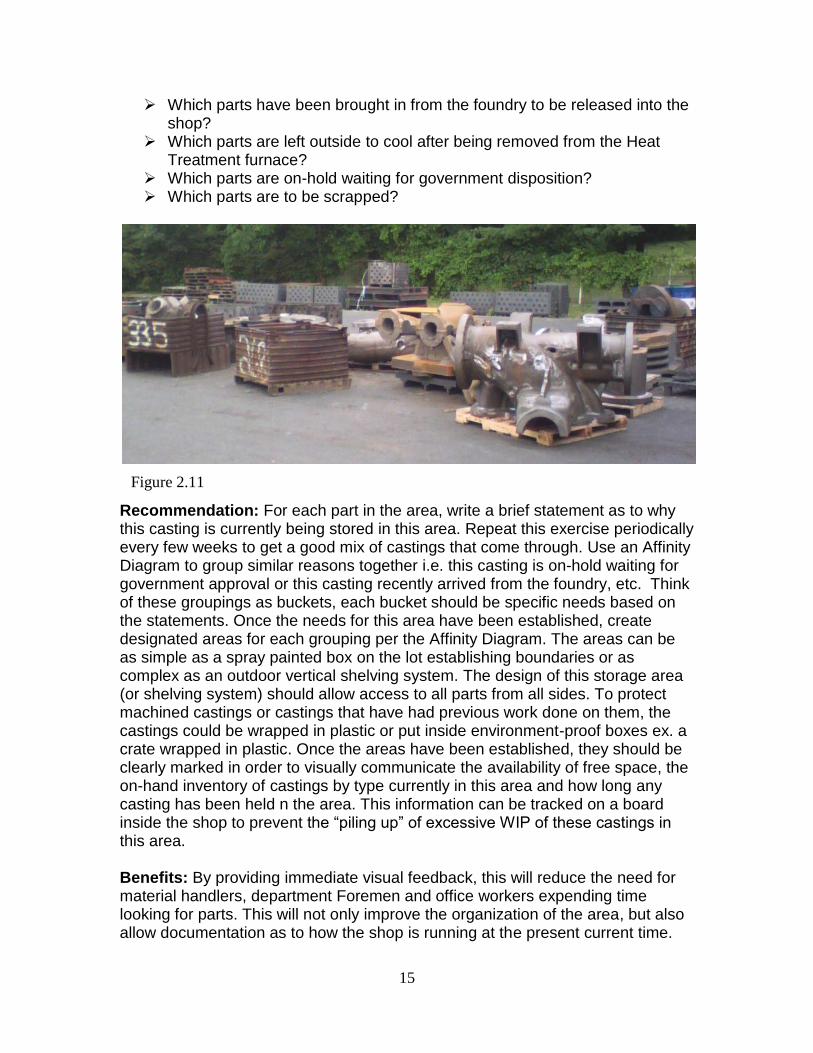
For example is there too much work being put on hold? Such efficient warehouse design will reduce the tendency for people to dump parts since this results in a LIFO (Last In First Out) withdrawal process and makes for more difficult access to castings dropped in the area at an earlier date. Figure 2.12 presents a possible solution for the design of this storage area without showing access lanes between the sections which should be included.
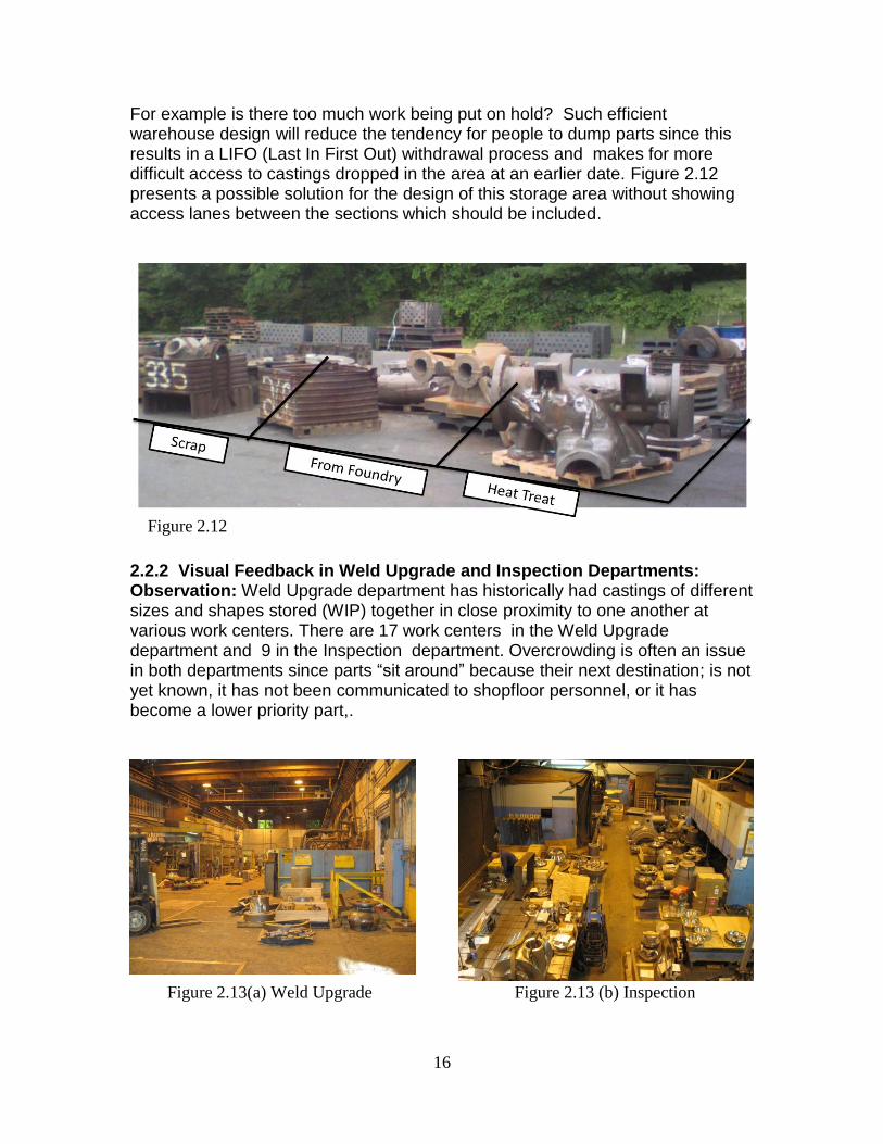
2.2.2 Visual Feedback in Weld Upgrade and Inspection Departments: Observation: Weld Upgrade department has historically had castings of different sizes and shapes stored (WIP) together in close proximity to one another at various work centers. There are 17 work centers in the Weld Upgrade department and 9 in the Inspection department. Overcrowding is often an issue in both departments since parts “sit around” because their next destination; is not yet known, it has not been communicated to shopfloor personnel, or it has become a lower priority part,.
Figure 2.12
Figure 2.13 (b) Inspection Figure 2.13(a) Weld Upgrade
17
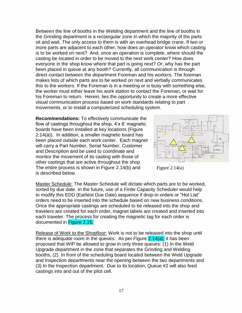
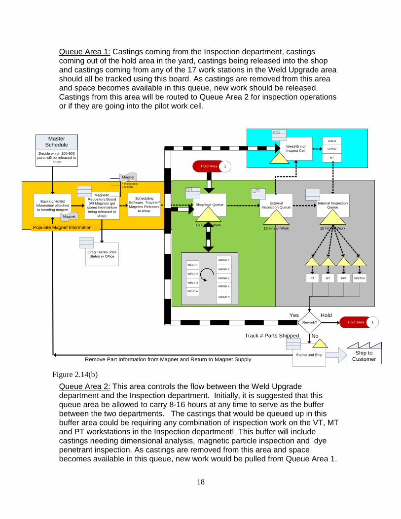
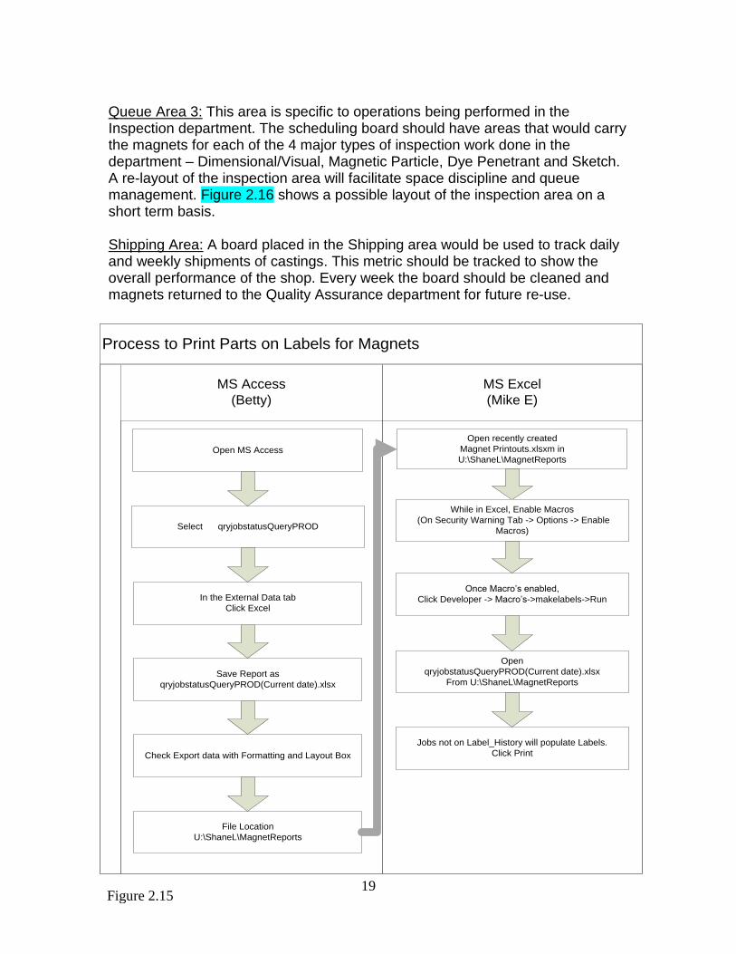
Between the line of booths in the Welding department and the line of booths in the Grinding department is a rectangular zone in which the majority of the parts sit and wait. The only access to them is with an overhead bridge crane. If two or more parts are adjacent to each other, how does an operator know which casting is to be worked on next? And, once an operation is complete, where should the casting be located in order to be moved to the next work center? How does everyone in the shop know where that part is going next? Or, why has the part been placed in queue at any booth? Currently, all communication is through direct contact between the department Foreman and his workers. The foreman makes lists of which parts are to be worked on next and verbally communicates this to the workers. If the Foreman is in a meeting or is busy with something else, the worker must either leave his work station to contact the Foreman, or wait for his Foreman to return. Herein, lies the opportunity to create a more effective visual communication process based on work standards relating to part movements, or to install a computerized scheduling system. Recommendations: To effectively communicate the flow of castings throughout the shop, 4’x 6’ magnetic boards have been installed at key locations (Figure 2.14(a)). In addition, a smaller magnetic board has been placed outside each work center. Each magnet will carry a Part Number, Serial Number, Customer and Description and be used to coordinate and monitor the movement of its casting with those of other castings that are active throughout the shop. The entire process is shown in Figure 2.14(b) and is described below. Master Schedule: The Master Schedule will dictate which parts are to be worked, sorted by due date. In the future, use of a Finite Capacity Scheduler would help to modify this EDD (Earliest Due Date) sequence if drop-in orders or “Hot List” orders need to be inserted into the schedule based on new business conditions. Once the appropriate castings are scheduled to be released into the shop and travelers are created for each order, magnet labels are created and inserted into each traveler. The process for creating the magnetic tag for each order is documented in Figure 2.15. Release of Work to the Shopfloor: Work is not to be released into the shop until there is adequate room in the queues. As per Figure 2.14(a), it has been proposed that WIP be allowed to grow in only three queues: (1) In the Weld Upgrade department in the zone that separates the Grinding and Welding booths, (2) In front of the scheduling board located between the Weld Upgrade and Inspection departments near the opening between the two departments and (3) In the Inspection department. Due to its location, Queue #2 will also feed castings into and out of the pilot cell.
Figure 2.14(a)
18
Queue Area 1: Castings coming from the Inspection department, castings coming out of the hold area in the yard, castings being released into the shop and castings coming from any of the 17 work stations in the Weld Upgrade area should all be tracked using this board. As castings are removed from this area and space becomes available in this queue, new work should be released. Castings from this area will be routed to Queue Area 2 for inspection operations or if they are going into the pilot work cell. Queue Area 2: This area controls the flow between the Weld Upgrade department and the Inspection department. Initially, it is suggested that this queue area be allowed to carry 8-16 hours at any time to serve as the buffer between the two departments. The castings that would be queued up in this buffer area could be requiring any combination of inspection work on the VT, MT and PT workstations in the Inspection department! This buffer will include castings needing dimensional analysis, magnetic particle inspection and dye penetrant inspection. As castings are removed from this area and space becomes available in this queue, new work would be pulled from Queue Area 1.
Stamp and Ship
Greg Tracks Jobs
Status in Office
Magnetic
Repository Board
(All Magnets get
stored here before
being released to
shop)
Scheduling
Software. Traveler/
Magnets Released
to shop.
Backlog/Hotlist
Information attached
to traveling magnet
Shopfloor Queue Internal Inspection
Queue
PT DIMMT SKETCH
External
Inspection Queue
Rework?
Ship to
Customer
Yes
No
Hold
Hold Area
WELD 4
WELD 3
WELD 2
WELD 1
GRIND 1
GRIND 2
GRIND 3
GRIND 4
GRIND 5
16 Hr’s of Work16 Hr’s of Work16 Hr’s of Work
Weld/Grind/
Inspect Cell
MT
WELD
GRIND
Decide which 100-500
parts will be released to
shop
Master
Schedule
Remove Part Information from Magnet and Return to Magnet Supply
1
Magnet
Magnet
= # jobs next
3 months
Populate Magnet Information
Track # Parts Shipped
Hold Area 1
Figure 2.14(b)
19
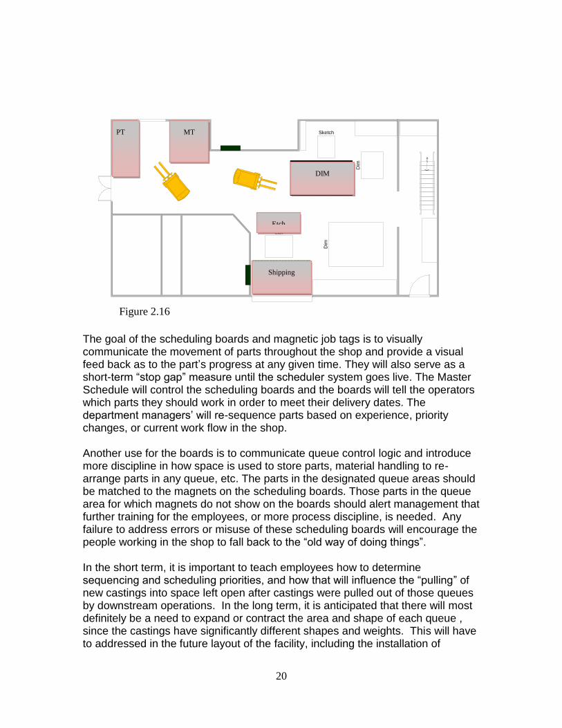
Queue Area 3: This area is specific to operations being performed in the Inspection department. The scheduling board should have areas that would carry the magnets for each of the 4 major types of inspection work done in the department – Dimensional/Visual, Magnetic Particle, Dye Penetrant and Sketch. A re-layout of the inspection area will facilitate space discipline and queue management. Figure 2.16 shows a possible layout of the inspection area on a short term basis. Shipping Area: A board placed in the Shipping area would be used to track daily and weekly shipments of castings. This metric should be tracked to show the overall performance of the shop. Every week the board should be cleaned and magnets returned to the Quality Assurance department for future re-use.
Process to Print Parts on Labels for Magnets
MS Access
(Betty)
MS Excel
(Mike E)
Open MS Access
Select qryjobstatusQueryPROD
In the External Data tab
Click Excel
Check Export data with Formatting and Layout Box
Save Report as
qryjobstatusQueryPROD(Current date).xlsx
File Location
U:\ShaneL\MagnetReports
Open recently created
Magnet Printouts.xlsxm in
U:\ShaneL\MagnetReports
While in Excel, Enable Macros
(On Security Warning Tab -> Options -> Enable
Macros)
Once Macro’s enabled,
Click Developer -> Macro’s->makelabels->Run
Open
qryjobstatusQueryPROD(Current date).xlsx
From U:\ShaneL\MagnetReports
Jobs not on Label_History will populate Labels.
Click Print
Figure 2.15
20
The goal of the scheduling boards and magnetic job tags is to visually communicate the movement of parts throughout the shop and provide a visual feed back as to the part’s progress at any given time. They will also serve as a short-term “stop gap” measure until the scheduler system goes live. The Master Schedule will control the scheduling boards and the boards will tell the operators which parts they should work in order to meet their delivery dates. The department managers’ will re-sequence parts based on experience, priority changes, or current work flow in the shop. Another use for the boards is to communicate queue control logic and introduce more discipline in how space is used to store parts, material handling to re-arrange parts in any queue, etc. The parts in the designated queue areas should be matched to the magnets on the scheduling boards. Those parts in the queue area for which magnets do not show on the boards should alert management that further training for the employees, or more process discipline, is needed. Any failure to address errors or misuse of these scheduling boards will encourage the people working in the shop to fall back to the “old way of doing things”. In the short term, it is important to teach employees how to determine sequencing and scheduling priorities, and how that will influence the “pulling” of new castings into space left open after castings were pulled out of those queues by downstream operations. In the long term, it is anticipated that there will most definitely be a need to expand or contract the area and shape of each queue , since the castings have significantly different shapes and weights. This will have to addressed in the future layout of the facility, including the installation of
Figure 2.16 D
im
Sketch
Dim
Etch
Up
PT Queue
54 sq. ft.
MAG Queue
51 sq. ft.
DIM Queue
88 sq. ft.
Etch Queue
9 sq. ft.
Shipping Area
69 sq. ft.
PT MT
DIM
Shipping
Etch
21
material handling surfaces that would allow for the castings to be easily moved as order priorities change, castings are taken away, new castings arrive, and so on. Benefits: The creation of a visual management system will increase LOSE (Line Of Sight Efficiency) throughout the facility by at least 50%. This willreduce the time spent looking for & tracking castings and also the amount of time personally directing technicians on which castings to be worked next. This will allow managers to reallocate time from the tactical to more strategic type of work including training and mentoring. Sales employees will more quickly be able to report on the status of different orders when customers call in and any employee will be able to determine where a casting is by going to the boards vs walking about the floors. Ideas for Future Consideration: Possible improvements to the visual communication system include linking part movements to the change in position of RFID tags. The RFID tags are able to document where a part is at anytime, and when the part was last moved and how long the part has sat at the current location. By providing a start and end time for each transfer/move made by any part, employees could track in real-time the progress of a part. For example by comparing the current time spent on a part compared to previous data as to the last time the part was made in the shop. Tracking the deviation of actual time spent working on a part and estimated time spent working on a part will allow the Sales department to more accurately predict and quote lead times for parts. Alternatively, once the ProfitKey system is fully operational, a barcode system with mobile scanning gun could be used. The castings would need to be checked in and out of work centers where the time spent in the work center would be recorded. Such electronic tracking of the movement of parts through the queues will progressively reduce reliance on the manual visual communication system. It would also eliminate the labor time lost because employees currently must complete time sheets once the part has left the workstation. Lastly, it may be possible to contact the local phone company and install an internal communication system whereby the foremen and managers could communicate just in time on any matter that relates to timely completion of work on different castings.
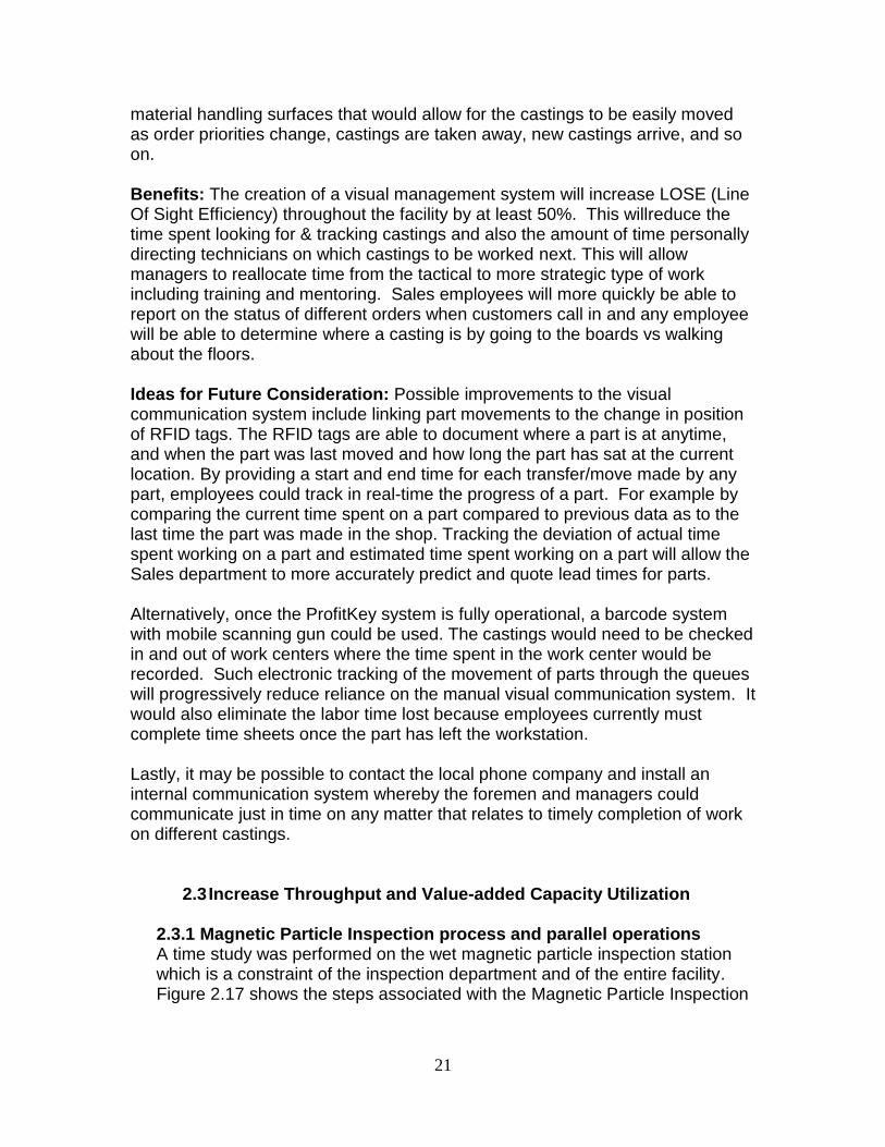
2.3 Increase Throughput and Value-added Capacity Utilization 2.3.1 Magnetic Particle Inspection process and parallel operations A time study was performed on the wet magnetic particle inspection station which is a constraint of the inspection department and of the entire facility. Figure 2.17 shows the steps associated with the Magnetic Particle Inspection
22
process and time taken to perform a typical task in this booth from start-to-finish.
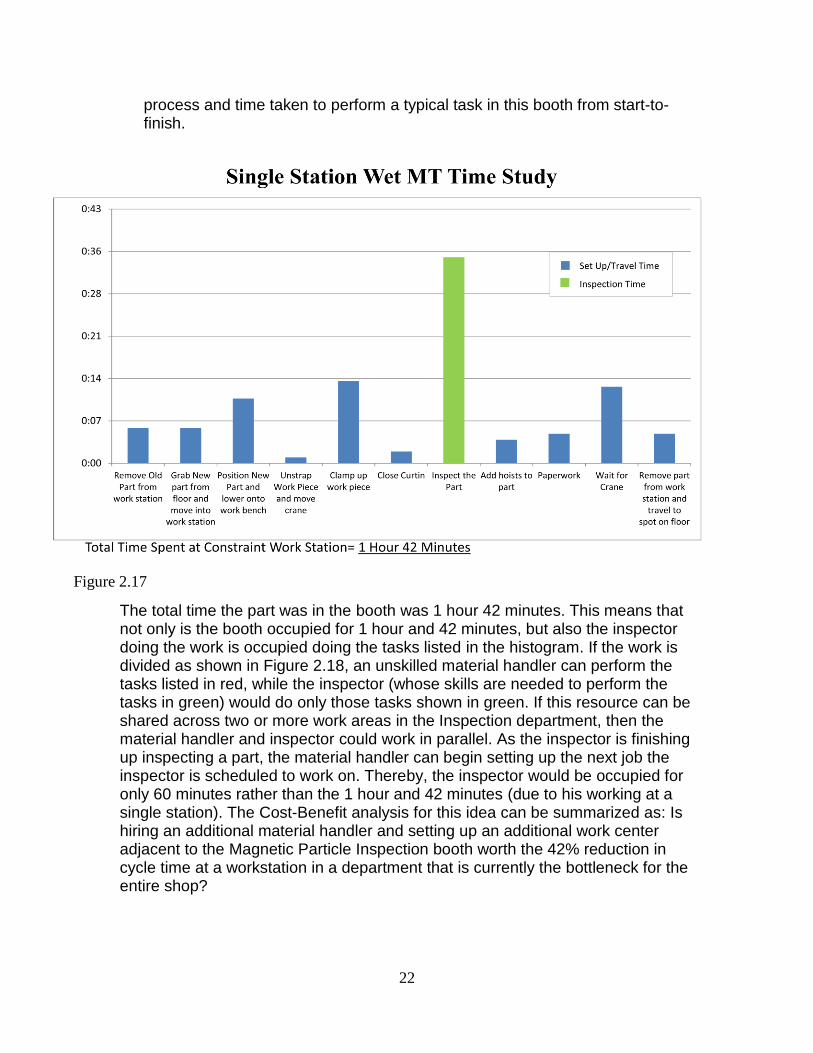
The total time the part was in the booth was 1 hour 42 minutes. This means that not only is the booth occupied for 1 hour and 42 minutes, but also the inspector doing the work is occupied doing the tasks listed in the histogram. If the work is divided as shown in Figure 2.18, an unskilled material handler can perform the tasks listed in red, while the inspector (whose skills are needed to perform the tasks in green) would do only those tasks shown in green. If this resource can be shared across two or more work areas in the Inspection department, then the material handler and inspector could work in parallel. As the inspector is finishing up inspecting a part, the material handler can begin setting up the next job the inspector is scheduled to work on. Thereby, the inspector would be occupied for only 60 minutes rather than the 1 hour and 42 minutes (due to his working at a single station). The Cost-Benefit analysis for this idea can be summarized as: Is hiring an additional material handler and setting up an additional work center adjacent to the Magnetic Particle Inspection booth worth the 42% reduction in cycle time at a workstation in a department that is currently the bottleneck for the entire shop?
Figure 2.17
23
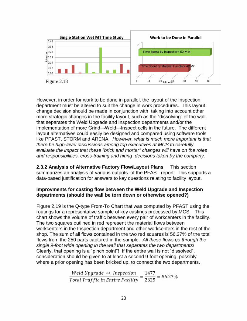
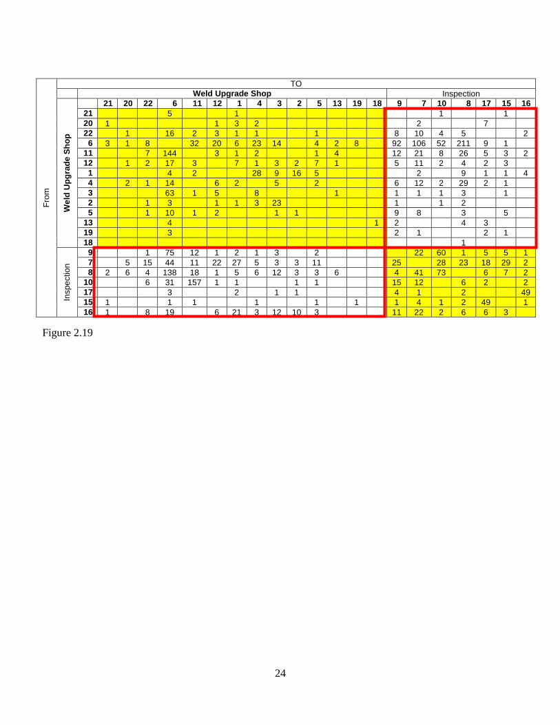
However, in order for work to be done in parallel, the layout of the Inspection department must be altered to suit the change in work procedures. This layout change decision should be made in conjunction with taking into account other more strategic changes in the facility layout, such as the “dissolving” of the wall that separates the Weld Upgrade and Inspection departments and/or the implementation of more Grind→Weld→Inspect cells in the future. The different layout alternatives could easily be designed and compared using software tools like PFAST, STORM and ARENA. However, what is much more important is that there be high-level discussions among top executives at MCS to carefully evaluate the impact that these “brick and mortar” changes will have on the roles and responsibilities, cross-training and hiring decisions taken by the company. 2.3.2 Analysis of Alternative Factory Flow/Layout Plans This section summarizes an analysis of various outputs of the PFAST report. This supports a data-based justification for answers to key questions relating to facility layout. Improvments for casting flow between the Weld Upgrade and Inspection departments (should the wall be torn down or otherwise opened?) Figure 2.19 is the Q-type From-To Chart that was computed by PFAST using the routings for a representative sample of key castings processed by MCS. This chart shows the volume of traffic between every pair of workcenters in the facility. The two squares outlined in red represent the material flows between workcenters in the Inspection department and other workcenters in the rest of the shop. The sum of all flows contained in the two red squares is 56.27% of the total flows from the 250 parts captured in the sample. All these flows go through the single 9-foot wide opening in the wall that separates the two departments! Clearly, that opening is a “pinch point”! If the entire wall is not “dissolved”, consideration should be given to at least a second 9-foot opening, possibly where a prior opening has been bricked up, to connect the two departments.
Figure 2.18
24
Fro
m
TO
Weld Upgrade Shop Inspection
We
ld U
pg
rad
e S
ho
p
21 20 22 6 11 12 1 4 3 2 5 13 19 18 9 7 10 8 17 15 16
21 5 1
1 1
20 1 1 3 2 2 7
22 1 16 2 3 1 1 1 8 10 4 5 2
6 3 1 8 32 20 6 23 14 4 2 8 92 106 52 211 9 1
11 7 144 3 1 2 1 4 12 21 8 26 5 3 2
12 1 2 17 3 7 1 3 2 7 1 5 11 2 4 2 3
1 4 2 28 9 16 5 2 9 1 1 4
4 2 1 14 6 2 5 2 6 12 2 29 2 1
3 63 1 5 8 1 1 1 1 3 1
2 1 3 1 1 3 23 1 1 2
5 1 10 1 2 1 1 9 8 3 5
13 4 1 2 4 3
19 3 2 1 2 1
18 1
Inspe
ctio
n
9 1 75 12 1 2 1 3 2 22 60 1 5 5 1
7 5 15 44 11 22 27 5 3 3 11 25 28 23 18 29 2
8 2 6 4 138 18 1 5 6 12 3 3 6 4 41 73 6 7 2
10 6 31 157 1 1 1 1 15 12 6 2 2
17 3 2 1 1 4 1 2 49
15 1 1 1 1 1 1 1 4 1 2 49 1
16 1 8 19 6 21 3 12 10 3 11 22 2 6 6 3
Figure 2.19
25
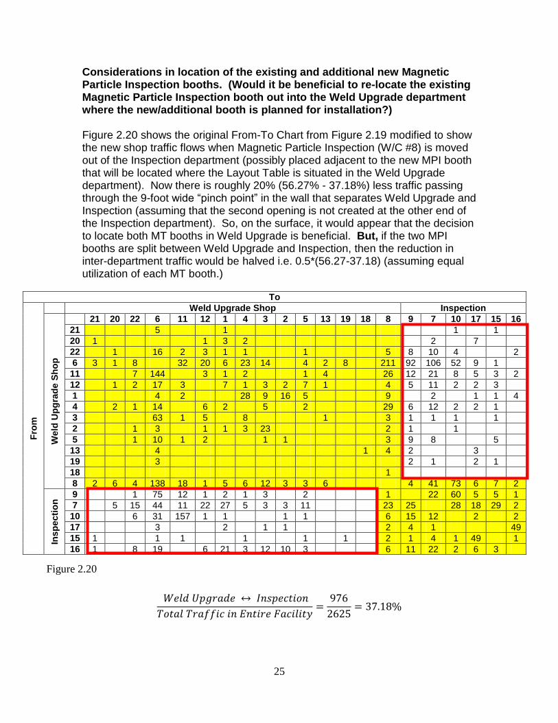
Considerations in location of the existing and additional new Magnetic Particle Inspection booths. (Would it be beneficial to re-locate the existing Magnetic Particle Inspection booth out into the Weld Upgrade department where the new/additional booth is planned for installation?) Figure 2.20 shows the original From-To Chart from Figure 2.19 modified to show the new shop traffic flows when Magnetic Particle Inspection (W/C #8) is moved out of the Inspection department (possibly placed adjacent to the new MPI booth that will be located where the Layout Table is situated in the Weld Upgrade department). Now there is roughly 20% (56.27% - 37.18%) less traffic passing through the 9-foot wide “pinch point” in the wall that separates Weld Upgrade and Inspection (assuming that the second opening is not created at the other end of the Inspection department). So, on the surface, it would appear that the decision to locate both MT booths in Weld Upgrade is beneficial. But, if the two MPI booths are split between Weld Upgrade and Inspection, then the reduction in inter-department traffic would be halved i.e. 0.5*(56.27-37.18) (assuming equal utilization of each MT booth.)
To
Fro
m
Weld Upgrade Shop Inspection
Weld
Up
gra
de S
ho
p
21 20 22 6 11 12 1 4 3 2 5 13 19 18 8 9 7 10 17 15 16
21 5 1 1 1
20 1 1 3 2 2 7
22 1 16 2 3 1 1 1 5 8 10 4 2
6 3 1 8 32 20 6 23 14 4 2 8 211 92 106 52 9 1
11 7 144 3 1 2 1 4 26 12 21 8 5 3 2
12 1 2 17 3 7 1 3 2 7 1 4 5 11 2 2 3
1 4 2 28 9 16 5 9 2 1 1 4
4 2 1 14 6 2 5 2 29 6 12 2 2 1
3 63 1 5 8 1 3 1 1 1 1
2 1 3 1 1 3 23 2 1 1
5 1 10 1 2 1 1 3 9 8 5
13 4 1 4 2 3
19 3 2 1 2 1
18 1
8 2 6 4 138 18 1 5 6 12 3 3 6 4 41 73 6 7 2
Insp
ecti
on
9 1 75 12 1 2 1 3 2 1 22 60 5 5 1
7 5 15 44 11 22 27 5 3 3 11 23 25 28 18 29 2
10 6 31 157 1 1 1 1 6 15 12 2 2
17 3 2 1 1 2 4 1 49
15 1 1 1 1 1 1 2 1 4 1 49 1
16 1 8 19 6 21 3 12 10 3 6 11 22 2 6 3
Figure 2.20
26
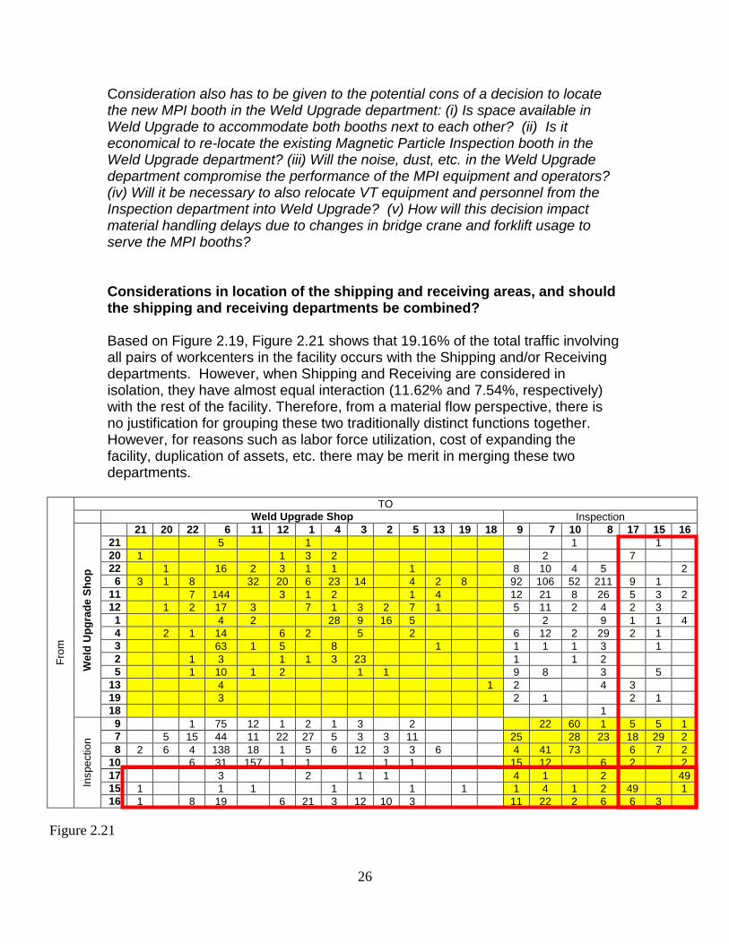
Consideration also has to be given to the potential cons of a decision to locate the new MPI booth in the Weld Upgrade department: (i) Is space available in Weld Upgrade to accommodate both booths next to each other? (ii) Is it economical to re-locate the existing Magnetic Particle Inspection booth in the Weld Upgrade department? (iii) Will the noise, dust, etc. in the Weld Upgrade department compromise the performance of the MPI equipment and operators? (iv) Will it be necessary to also relocate VT equipment and personnel from the Inspection department into Weld Upgrade? (v) How will this decision impact material handling delays due to changes in bridge crane and forklift usage to serve the MPI booths? Considerations in location of the shipping and receiving areas, and should the shipping and receiving departments be combined? Based on Figure 2.19, Figure 2.21 shows that 19.16% of the total traffic involving all pairs of workcenters in the facility occurs with the Shipping and/or Receiving departments. However, when Shipping and Receiving are considered in isolation, they have almost equal interaction (11.62% and 7.54%, respectively) with the rest of the facility. Therefore, from a material flow perspective, there is no justification for grouping these two traditionally distinct functions together. However, for reasons such as labor force utilization, cost of expanding the facility, duplication of assets, etc. there may be merit in merging these two departments.
Fro
m
TO
Weld Upgrade Shop Inspection
We
ld U
pg
rad
e S
ho
p
21 20 22 6 11 12 1 4 3 2 5 13 19 18 9 7 10 8 17 15 16
21 5 1 1
1
20 1 1 3 2 2 7
22 1 16 2 3 1 1 1 8 10 4 5 2
6 3 1 8 32 20 6 23 14 4 2 8 92 106 52 211 9 1
11 7 144 3 1 2 1 4 12 21 8 26 5 3 2
12 1 2 17 3 7 1 3 2 7 1 5 11 2 4 2 3
1 4 2 28 9 16 5 2 9 1 1 4
4 2 1 14 6 2 5 2 6 12 2 29 2 1
3 63 1 5 8 1 1 1 1 3 1
2 1 3 1 1 3 23 1 1 2
5 1 10 1 2 1 1 9 8 3 5
13 4 1 2 4 3
19 3 2 1 2 1
18 1
Inspe
ctio
n
9 1 75 12 1 2 1 3 2 22 60 1 5 5 1
7 5 15 44 11 22 27 5 3 3 11 25 28 23 18 29 2
8 2 6 4 138 18 1 5 6 12 3 3 6 4 41 73 6 7 2
10 6 31 157 1 1 1 1 15 12 6 2 2
17 3 2 1 1 4 1 2 49
15 1 1 1 1 1 1 1 4 1 2 49 1
16 1 8 19 6 21 3 12 10 3 11 22 2 6 6 3
Figure 2.21
27
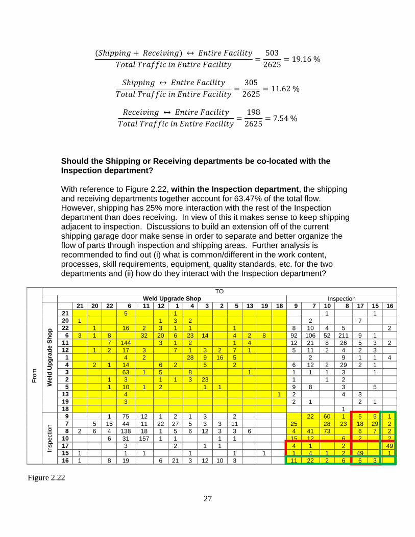
Should the Shipping or Receiving departments be co-located with the Inspection department? With reference to Figure 2.22, within the Inspection department, the shipping and receiving departments together account for 63.47% of the total flow. However, shipping has 25% more interaction with the rest of the Inspection department than does receiving. In view of this it makes sense to keep shipping adjacent to inspection. Discussions to build an extension off of the current shipping garage door make sense in order to separate and better organize the flow of parts through inspection and shipping areas. Further analysis is recommended to find out (i) what is common/different in the work content, processes, skill requirements, equipment, quality standards, etc. for the two departments and (ii) how do they interact with the Inspection department?
Fro
m
TO
Weld Upgrade Shop Inspection
We
ld U
pg
rad
e S
ho
p
21 20 22 6 11 12 1 4 3 2 5 13 19 18 9 7 10 8 17 15 16
21 5 1 1 1
20 1 1 3 2 2 7
22 1 16 2 3 1 1 1 8 10 4 5 2
6 3 1 8 32 20 6 23 14 4 2 8 92 106 52 211 9 1
11 7 144 3 1 2 1 4 12 21 8 26 5 3 2
12 1 2 17 3 7 1 3 2 7 1 5 11 2 4 2 3
1 4 2 28 9 16 5 2 9 1 1 4
4 2 1 14 6 2 5 2 6 12 2 29 2 1
3 63 1 5 8 1 1 1 1 3 1
2 1 3 1 1 3 23 1 1 2
5 1 10 1 2 1 1 9 8 3 5
13 4 1 2 4 3
19 3 2 1 2 1
18 1
Inspe
ctio
n
9 1 75 12 1 2 1 3 2 22 60 1 5 5 1
7 5 15 44 11 22 27 5 3 3 11 25 28 23 18 29 2
8 2 6 4 138 18 1 5 6 12 3 3 6 4 41 73 6 7 2
10 6 31 157 1 1 1 1
15 12 6 2 2
17 3 2 1 1 4 1 2 49
15 1 1 1 1 1 1
1 4 1 2 49 1
16 1 8 19 6 21 3 12 10 3 11 22 2 6 6 3
Figure 2.22
28
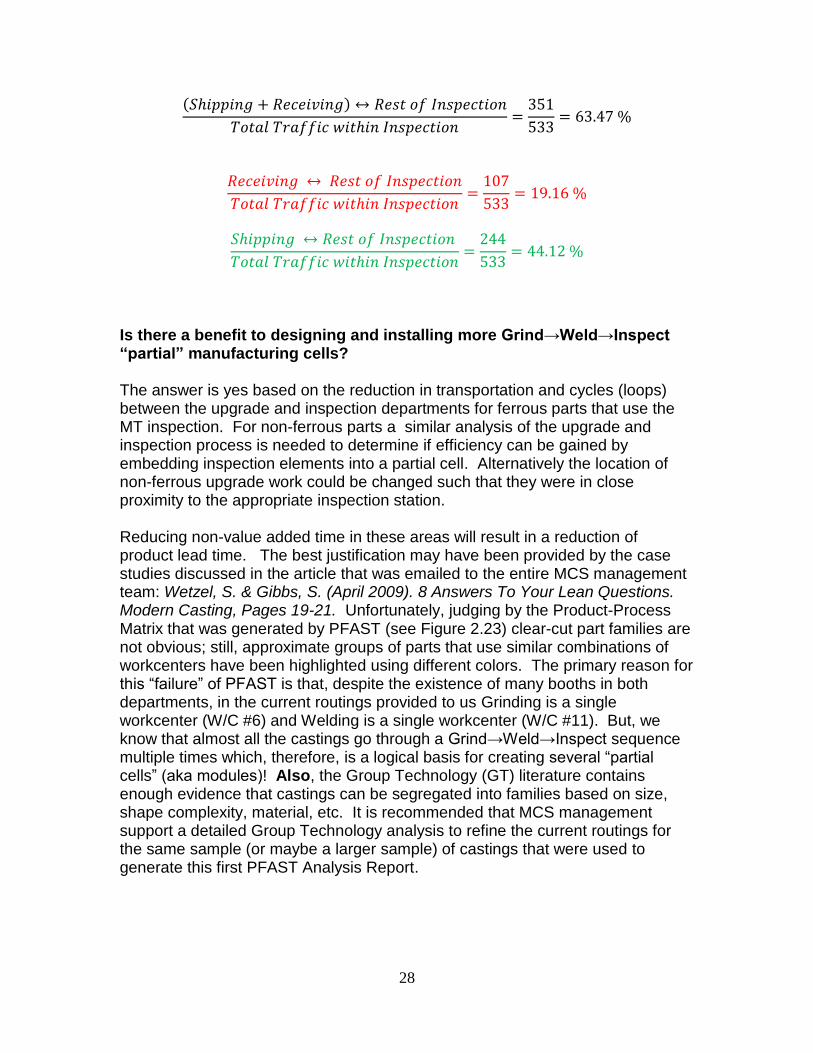
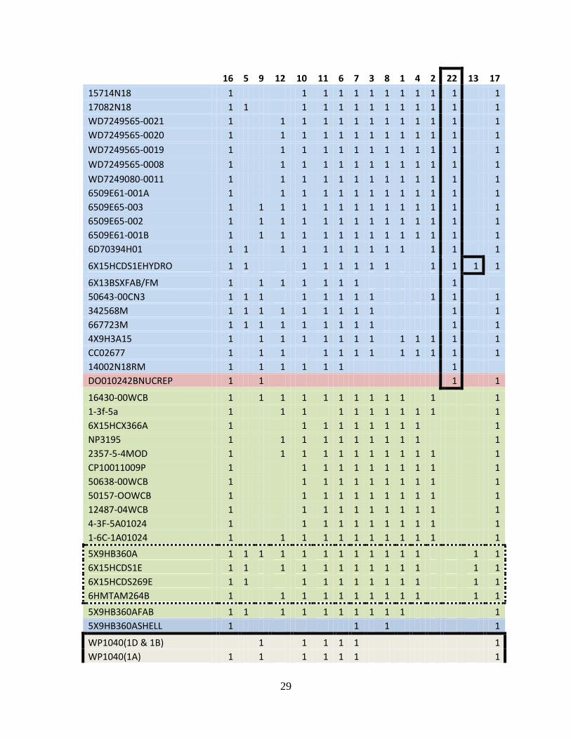
Is there a benefit to designing and installing more Grind→Weld→Inspect “partial” manufacturing cells? The answer is yes based on the reduction in transportation and cycles (loops) between the upgrade and inspection departments for ferrous parts that use the MT inspection. For non-ferrous parts a similar analysis of the upgrade and inspection process is needed to determine if efficiency can be gained by embedding inspection elements into a partial cell. Alternatively the location of non-ferrous upgrade work could be changed such that they were in close proximity to the appropriate inspection station. Reducing non-value added time in these areas will result in a reduction of product lead time. The best justification may have been provided by the case studies discussed in the article that was emailed to the entire MCS management team: Wetzel, S. & Gibbs, S. (April 2009). 8 Answers To Your Lean Questions. Modern Casting, Pages 19-21. Unfortunately, judging by the Product-Process Matrix that was generated by PFAST (see Figure 2.23) clear-cut part families are not obvious; still, approximate groups of parts that use similar combinations of workcenters have been highlighted using different colors. The primary reason for this “failure” of PFAST is that, despite the existence of many booths in both departments, in the current routings provided to us Grinding is a single workcenter (W/C #6) and Welding is a single workcenter (W/C #11). But, we know that almost all the castings go through a Grind→Weld→Inspect sequence multiple times which, therefore, is a logical basis for creating several “partial cells” (aka modules)! Also, the Group Technology (GT) literature contains enough evidence that castings can be segregated into families based on size, shape complexity, material, etc. It is recommended that MCS management support a detailed Group Technology analysis to refine the current routings for the same sample (or maybe a larger sample) of castings that were used to generate this first PFAST Analysis Report.
29
16 5 9 12 10 11 6 7 3 8 1 4 2 22 13 17
15714N18 1 1 1 1 1 1 1 1 1 1 1 1
17082N18 1 1 1 1 1 1 1 1 1 1 1 1 1
WD7249565-0021 1 1 1 1 1 1 1 1 1 1 1 1 1
WD7249565-0020 1 1 1 1 1 1 1 1 1 1 1 1 1
WD7249565-0019 1 1 1 1 1 1 1 1 1 1 1 1 1
WD7249565-0008 1 1 1 1 1 1 1 1 1 1 1 1 1
WD7249080-0011 1 1 1 1 1 1 1 1 1 1 1 1 1
6509E61-001A 1 1 1 1 1 1 1 1 1 1 1 1 1
6509E65-003 1 1 1 1 1 1 1 1 1 1 1 1 1 1
6509E65-002 1 1 1 1 1 1 1 1 1 1 1 1 1 1
6509E61-001B 1 1 1 1 1 1 1 1 1 1 1 1 1 1
6D70394H01 1 1 1 1 1 1 1 1 1 1 1 1 1
6X15HCDS1EHYDRO 1 1 1 1 1 1 1 1 1 1 1 1
6X13BSXFAB/FM 1 1 1 1 1 1 1 1
50643-00CN3 1 1 1 1 1 1 1 1 1 1 1
342568M 1 1 1 1 1 1 1 1 1 1 1
667723M 1 1 1 1 1 1 1 1 1 1 1
4X9H3A15 1 1 1 1 1 1 1 1 1 1 1 1 1
CC02677 1 1 1 1 1 1 1 1 1 1 1 1
14002N18RM 1 1 1 1 1 1 1
DO010242BNUCREP 1 1 1 1
16430-00WCB 1 1 1 1 1 1 1 1 1 1 1 1
1-3f-5a 1 1 1 1 1 1 1 1 1 1 1
6X15HCX366A 1 1 1 1 1 1 1 1 1 1
NP3195 1 1 1 1 1 1 1 1 1 1 1
2357-5-4MOD 1 1 1 1 1 1 1 1 1 1 1 1
CP10011009P 1 1 1 1 1 1 1 1 1 1 1
50638-00WCB 1 1 1 1 1 1 1 1 1 1 1
50157-OOWCB 1 1 1 1 1 1 1 1 1 1 1
12487-04WCB 1 1 1 1 1 1 1 1 1 1 1
4-3F-5A01024 1 1 1 1 1 1 1 1 1 1 1
1-6C-1A01024 1 1 1 1 1 1 1 1 1 1 1 1
5X9HB360A 1 1 1 1 1 1 1 1 1 1 1 1 1 1
6X15HCDS1E 1 1 1 1 1 1 1 1 1 1 1 1 1
6X15HCDS269E 1 1 1 1 1 1 1 1 1 1 1 1
6HMTAM264B 1 1 1 1 1 1 1 1 1 1 1 1
5X9HB360AFAB 1 1 1 1 1 1 1 1 1 1 1
5X9HB360ASHELL 1 1 1 1
WP1040(1D & 1B) 1 1 1 1 1 1
WP1040(1A) 1 1 1 1 1 1 1
30
WP1040 1 1 1 1 1 1 1 1
WP1040 (1B & 1C) 1 1 1 1 1 1 1 1
WP1040 (1E(2) & 1D) 1 1 1 1 1 1 1 1
WP1040(1C & 1E(1)) 1 1 1 1 1 1 1 1
WP1040-1D 1 1 1 1 1 1 1 1
WP1040(1A & 1B) 1 1 1 1 1 1 1
WP1040-1B 1 1 1 1 1 1 1 1
CDO3693 1 1 1 1 1 1 1
1-3S-11B 1 1 1 1 1 1 1 1 1
1-2-DB-21A 1 1 1 1 1 1 1 1 1
CC02836C95400 1 1 1 1 1 1 1 1 1 1
CC04513 1 1 1 1 1 1 1 1 1
024-47-30-1032CF8 1 1 1 1 1 1 1 1 1 1
CC04513LT2 1 1 1 1 1 1 1 1 1 1
CC04513LT3 1 1 1 1 1 1 1 1 1 1
CC02771 1 1 1 1 1 1 1 1 1 1 1 1
21289-1WC6 1 1 1 1 1 1 1 1 1 1 1 1
UB4567B 1 1 1 1 1 1 1 1 1 1
21389-18M 1 1 1 1 1 1 1 1 1
1086-5-4 1 1 1 1 1 1 1 1
UB4568A 1 1 1 1 1 1 1 1 1
UB4567A 1 1 1 1 1 1 1 1 1
CC02450 1 1 1 1 1 1
CD03700 1 1 1 1 1
CD03699 1 1 1 1 1 1
WP1040 (1A & 1B) 1 1 1
WP1040-1A 1 1 1
WP1040-1C 1 1 1
WP1040-1E(1) 1 1 1
WP1040-1E(2) 1 1 1
064-18164-000 1 1 1
EVNBY00109302 1 1 1
EVNDBY00109202 1 1 1
NP244811RLI 1 1 1
6X15HCX56AX2 1 1
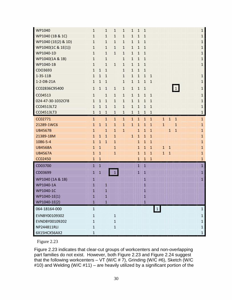
Figure 2.23 indicates that clear-cut groups of workcenters and non-overlapping part families do not exist. However, both Figure 2.23 and Figure 2.24 suggest that the following workcenters – VT (W/C # 7), Grinding (W/C #6), Sketch (W/C #10) and Welding (W/C #11) – are heavily utilized by a significant portion of the
Figure 2.23
31
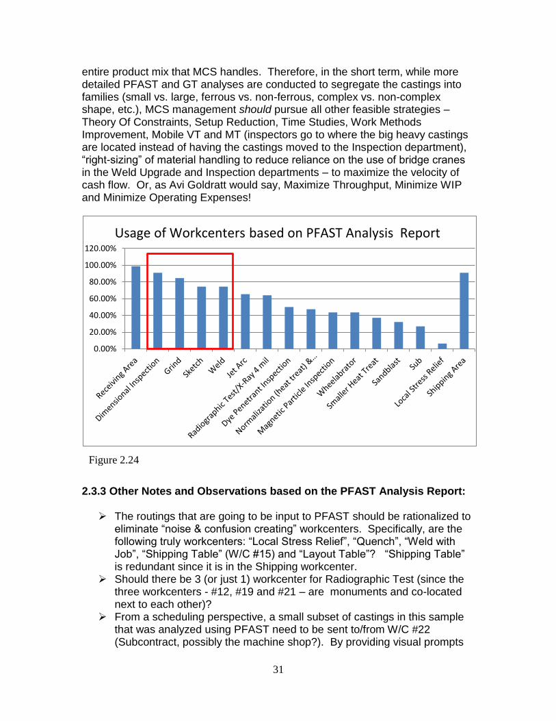
entire product mix that MCS handles. Therefore, in the short term, while more detailed PFAST and GT analyses are conducted to segregate the castings into families (small vs. large, ferrous vs. non-ferrous, complex vs. non-complex shape, etc.), MCS management should pursue all other feasible strategies – Theory Of Constraints, Setup Reduction, Time Studies, Work Methods Improvement, Mobile VT and MT (inspectors go to where the big heavy castings are located instead of having the castings moved to the Inspection department), “right-sizing” of material handling to reduce reliance on the use of bridge cranes in the Weld Upgrade and Inspection departments – to maximize the velocity of cash flow. Or, as Avi Goldratt would say, Maximize Throughput, Minimize WIP and Minimize Operating Expenses!
2.3.3 Other Notes and Observations based on the PFAST Analysis Report:
The routings that are going to be input to PFAST should be rationalized to eliminate “noise & confusion creating” workcenters. Specifically, are the following truly workcenters: “Local Stress Relief”, “Quench”, “Weld with Job”, “Shipping Table” (W/C #15) and “Layout Table”? “Shipping Table” is redundant since it is in the Shipping workcenter.
Should there be 3 (or just 1) workcenter for Radiographic Test (since the three workcenters - #12, #19 and #21 – are monuments and co-located next to each other)?
From a scheduling perspective, a small subset of castings in this sample that was analyzed using PFAST need to be sent to/from W/C #22 (Subcontract, possibly the machine shop?). By providing visual prompts
0.00%
20.00%
40.00%
60.00%
80.00%
100.00%
120.00%
Usage of Workcenters based on PFAST Analysis Report
Figure 2.24

32
to the shop employees. For example enclose their travelers in a different color plastic jacket, these castings could always be given a higher priority since one can expect their cycle times to completion to be higher than the rest of the castings that do not require to be sent for machining, or other subcontract, operations.