Embed Size (px)
Citation preview

IMPLEMENTATION OF VERTICAL HANDOFF ALGORITHM BETWEEN
IEEE802.11 WLAN AND CDMA CELLULAR NETWORK
by
MARY NARISETTI
Under the Direction of Yi Pan
ABSTRACT
Today’s wireless users expect great things from tomorrow’s wireless networks.
These expectations have been fueled by hype about what the next generations of wireless
networks will offer. The rapid increase of wireless subscribers increases the quality of
services anytime, anywhere, and by any-media becoming indispensable. Integration of
various networks such as CDMA2000 and wireless LAN into IP-based networks is
required in these kinds of services, which further requires a seamless vertical handoff to 4th
generation wireless networks.
The proposed handoff algorithm between WLAN and CDMA2000 cellular
network is implemented. The results of the simulation shows the behavior of the handoff
and the time spent in WLAN or CDMA. The number of weak signal beacons determines
whether a handoff is required or not. In this algorithm, traffic is classified into real-time
and non real-time services.
INDEX WORDS: CDMA2000, WLAN, Handoff, Real-time, Non real-time, Throughput
http://www.unik.no/personer/paalee/
IMPLEMENTATION OF VERTICAL HANDOFF ALGORITHM BETWEEN
IEEE802.11 WLAN AND CDMA CELLULAR NETWORK
by
MARY NARISETTI
A Thesis Submitted in Partial Fulfillment of the Requirements for the Degree of
Master of Science
in the College of Arts and Sciences
Georgia State University
2006
http://www.unik.no/personer/paalee/

Copyright by
Mary Narisetti
2006
http://www.unik.no/personer/paalee/

IMPLEMENTATION OF VERTICAL HANDOFF ALGORITHM BETWEEN
IEEE802.11 WLAN AND CDMA CELLULAR NETWORK
by
Mary Narisetti
Major Professor: Dr Yi Pan
Committee: Dr Anu G Bourgeois
Dr A P Preethy Electronic Version Approved: Office of Graduate Studies
College of Arts and Sciences
Georgia State University
August 2006
http://www.unik.no/personer/paalee/
iv
Acknowledgements
I would like to thank my advisor Dr. Yi Pan for his support and invaluable
guidance throughout my thesis work. I am also very grateful to the other members of
my thesis committee, Dr. Anu Bourgeois and Dr. Preethy for their advice and spending
their valuable time in reviewing the material.
I also want to thank my friends and family for their encouragement without
whose support I could not have lived through this dream of mine.
http://www.unik.no/personer/paalee/

v
Table of Contents
Acknowledgements............................................................................................................... iv
List of Figures.......................................................................................................................vi
List of Tables .......................................................................................................................vii
List of Abbreviations.........................................................................................................viii
1. Introduction ...................................................................................................................... 1
2. Literature Review ............................................................................................................ 6
3. Challenges in 4G Networks............................................................................................. 19
4. Handoff in Networks ...................................................................................................... 22
5. Vertical Handoff Procedure and Algorithm between IEEE802.11
WLAN and CDMA cellular network..... 33
6. Simulation and Implementation of Handoff algorithm.............................................. 42
7. Conclusion ....................................................................................................................... 54
8. Bibliography .................................................................................................................... 57
Appendix – A ....................................................................................................................... 59
Appendix – B ....................................................................................................................... 69
Appendix – C ....................................................................................................................... 70
http://www.unik.no/personer/paalee/

vi
List of Figures
Figure 1.1 The Cell Topology ............................................................................................... 2
Figure 2.2 4G Visions [3] .................................................................................................... 10
Figure 2.3 Possible Architectures for 4G Networks [22].................................................. 14
Figure 2.4 Network Technologies....................................................................................... 16
Figure 4.1 Simple PLMN [23] ............................................................................................ 22
Figure 4.2 Signal Quality Behaviors [23] ......................................................................... 24
Figure 4.3 Handoff Methods [23]....................................................................................... 27
Figure 4.4 Basic Handoff Scenarios [23] ........................................................................... 28
Figure 4.5 WLAN-CDMA Cellular Interconnection Architecture based on IP [24] .... 31
Figure 4.6 Mobile Host Protocol STACK [24] .................................................................. 32
Figure 5.1 MD Handoff Signaling Flow ............................................................................ 34
Figure 5.2 MU Handoff Signaling flow ............................................................................. 35
Table 5.1 Specifications of AP and BSS............................................................................ 37
Table 5.2 Application Traffics ........................................................................................... 37
Figure 5.3 Handoff algorithm between WLAN and CDMA [24].................................... 38
Figure 5.4 Control Mechanism of Handoff ....................................................................... 40
Figure 5.5 Transition Region.............................................................................................. 40
Figure 6.1 Structure of the C code that runs the Simulation........................................... 44
Figure 6.2 Plot of λ thresh (vs) Time Spent in WLAN..................................................... 46
Figure 6.3 Plot of λ thresh (vs) Time Spent in CDMA..................................................... 47
Figure 6.4 Plot of λr (vs) Time Spent in WLAN .............................................................. 48
Figure 6.5 Plot of λu (vs) Time Spent in WLAN ............................................................. 49
Figure 6.6 Plot of λn (vs) Time Spent in WLAN.............................................................. 50
Figure 6.7 Plot of λr (vs) Time Spent in CDMA ............................................................. 51
Figure 6.8 Plot of λu (vs) Time Spent in CDMA ............................................................. 52
Figure 6.9 Plot of λn (vs) Time Spent in CDMA............................................................... 53
http://www.unik.no/personer/paalee/

vii
List of Tables
Table 2.1 Short History of Mobile Telephone Technologies ........………………………. 6
Table 2.2 Wireless Network and Service Evolution.......................……………………….7
Table 5.1 Specifications of AP and BSS........................................……………………......36
Table 5.2 Application Traffics ..........................................................………………………37
http://www.unik.no/personer/paalee/

viii
List of Abbreviations
AP – Access Point
BS – Base Station
CMR – Call-to-Mobility Ratio
CDMA – Code Division Multiple Access
EDGE – Enhanced Data rates for Global Evolution
FDMA – Frequency Division Multiple Access
GSM – Global System for Mobile
GSM – Global System for Mobile Communication
GPRS – Global Packet Radio Service
HO - Handoff
IP- Internet Protocol
LAN – Local Area Network
LA – Location Area
LCMR – Local Call-to-Mobility Ratio
LRU – Least Recently Used
MH – Mobile Host
MA – Mobile Agent
MD – Mobile Download
MU – Mobile Upward
MT – Mobile Through
http://www.unik.no/personer/paalee/

ix
MSL – Media Selection Layer
PDA – Personal Digital Assistant
PAN – Personal Area Networking
PDC – Personal Digital Cellular
PSTN – Public Switched Telephone Network
QoS – Quality of Service
RF – Radio Frequency
RAN – Radio Access Networking
SDOs – Standards Development Organizations
SDR – Software Defined Radio
SS7 – Signaling System 7
SA – Subnet Agent
SAc – Subnet Agent
SMS – Short Message Service
TDMA – Time Division Multiple Access
TDMA – Time Division Multiple Access
UMTS – Universal Mobile Telecommunications System
WCDMA – Wideband Code Division Multiple Access
3G – Third Generation
3GPP – Third Generation Partnership Project
http://www.unik.no/personer/paalee/

1
1. Introduction
“The wireless telegraph is not difficult to understand. The ordinary telegraph is like a
long cat. You pull the tail in New York, and it meows in Los Angeles. The wireless is the
same, only without the cat.”-Albert Einstein
In the past decade, the telecommunications industry has witnessed an ever accelerated
growth of the usage of the mobile communications. As a result, the mobile communications
technology has evolved from the so-called second-generation (2G) technologies, GSM in
Europe, IS-95(CDMA) and IS-136 (TDMA) in USA, to the third generation (3G)
technologies. Along with the standards development for providing voice service to mobile
users, a group of standards to deliver data to the mobile users have evolved from both SDOs
(Standards development organisations) and industry. Systems and applications, such as Short
Message Service (SMS) for sending and receiving short text messages for mobile phone
users, have been built and continue to be developed.
The genius of the cellular system is the division of a city into small cells. This allows
extensive frequency reuse across a city, so that millions of people can use cell phones
simultaneously. In a typical analog cell-phone system in the United States, the cell-phone
carrier receives about 800 frequencies to use across the city. The carrier divides the entire
city into cells. Each cell is typically sized at about 10 square miles (26 square kilometers).
Cells are normally thought of as hexagons on a larger hexagonal grid, as shown in Figure1.1:
http://www.unik.no/personer/paalee/

2
Location Area
Base Station
Rings
Figure 1.1 The Cell Topology
Each cell has a base station that consists of a tower and a small building containing the
radio equipment that is used to communicate with Mobile Terminals over preassigned radio
frequencies.
Cell phones have low-power transmitters in them. Many cell phones have two signal
strengths: 0.6 watts and 3 watts [1]. The base station also transmits at low power. Low-power
transmitters have two advantages:
• The transmissions of a base station and the phones within its cell do not make it very
far outside that cell. Therefore, in Figure1.1, both of the cells in alternate rings and
non-adjacent cells can reuse the same frequency. The same frequencies can be reused
extensively across the city.
• The power consumption of a cell phone, which is normally battery-operated, is
relatively low. Low power corresponds to small batteries, and this is what has made
http://www.unik.no/personer/paalee/

3
handheld cellular phones possible.
The cellular approach requires a large number of base stations in a city of any size. A
typical large city can have hundreds of towers. But because so many people are using cell
phones, costs remain low per user. Each carrier in each city also runs one central office called the
Mobile Telephone Switching Office (MTSO). This office handles all of the phone
connections to the normal land-based phone system, and controls all of the base stations in the
region. Groups of several cells are connected to a Mobile Switching Center (MSC) through
which the calls are then routed to the telephone networks. The area serviced by a MSC is
called a Registration Area (RA) or Location Area (LA). A group of RA’s composes a Service
Area (SA). Each SA is serviced by a Home Location Register (HLR). A wireless network
may include several SAs and thus several HLRs.
All cell phones have special codes associated with them. These codes are used to
identify the phone, the phone's owner and the service provider. Electronic Serial Number
(ESN) (a unique 32-bit number programmed into the phone when it is manufactured), Mobile
Identification Number (MIN) (a 10-digit number derived from the owners phone's number), and
a System Identification Code (SID) (a unique 5-digit number that is assigned to each carrier
by the FCC-Federal Communications Commission (A U.S. government agency charged
with the task of regulating all forms of interstate and international communication)) are a few
of the standard cell phone codes employed. While the ESN is considered a permanent part
of the phone, both the MIN and SID codes are programmed into the phone when one
purchases a service plan and has the phone activated.
2G systems such as GSM, IS-95, and cdmaOne were designed to carry speech and low-
bit rate data. 3G systems were designed to provide higher data rate services. During the
http://www.unik.no/personer/paalee/
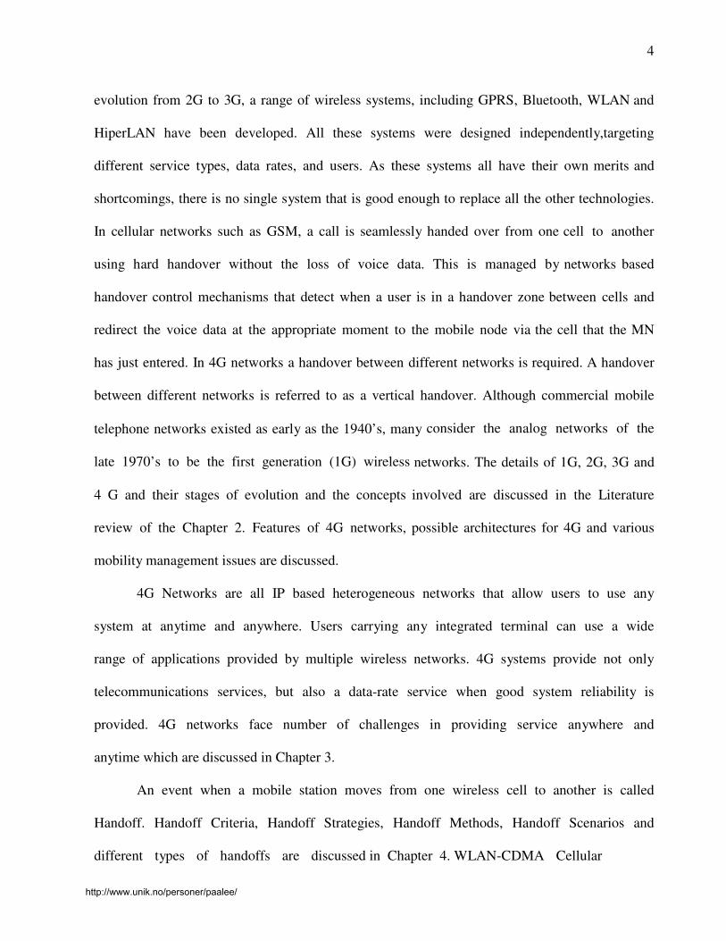
4
evolution from 2G to 3G, a range of wireless systems, including GPRS, Bluetooth, WLAN and
HiperLAN have been developed. All these systems were designed independently,targeting
different service types, data rates, and users. As these systems all have their own merits and
shortcomings, there is no single system that is good enough to replace all the other technologies.
In cellular networks such as GSM, a call is seamlessly handed over from one cell to another
using hard handover without the loss of voice data. This is managed by networks based
handover control mechanisms that detect when a user is in a handover zone between cells and
redirect the voice data at the appropriate moment to the mobile node via the cell that the MN
has just entered. In 4G networks a handover between different networks is required. A handover
between different networks is referred to as a vertical handover. Although commercial mobile
telephone networks existed as early as the 1940’s, many consider the analog networks of the
late 1970’s to be the first generation (1G) wireless networks. The details of 1G, 2G, 3G and
4 G and their stages of evolution and the concepts involved are discussed in the Literature
review of the Chapter 2. Features of 4G networks, possible architectures for 4G and various
mobility management issues are discussed.
4G Networks are all IP based heterogeneous networks that allow users to use any
system at anytime and anywhere. Users carrying any integrated terminal can use a wide
range of applications provided by multiple wireless networks. 4G systems provide not only
telecommunications services, but also a data-rate service when good system reliability is
provided. 4G networks face number of challenges in providing service anywhere and
anytime which are discussed in Chapter 3.
An event when a mobile station moves from one wireless cell to another is called
Handoff. Handoff Criteria, Handoff Strategies, Handoff Methods, Handoff Scenarios and
different types of handoffs are discussed in Chapter 4. WLAN-CDMA Cellular
http://www.unik.no/personer/paalee/

5
interconnection architecture based on IP [24] is discussed.
Chapter 5 discusses the Vertical handoff procedure and algorithm between WLAN and
CDMA cellular network. Two different types of handoffs are discussed in this chapter. Mobile
download handoff procedure in which mobile host moves from WLAN into CDMA network
and Mobile Upward handoff procedure in which mobile host moves from CDMA into WLAN
are discussed in detail. Chapter 6 discusses the simulation and code structure in detail.
In summary, this paper is organized as follows: Chapter 1 is the introduction. The
literature review is provided in the second chapter. Features of 4G networks and challenges
faced in deploying 4G networks are discussed in Chapter 3. Handoff in Networks is
discussed in chapter 4. The details of the Vertical Handoff Procedure and algorithm between
WLAN and CDMA are discussed in Chapter 5 with the details of the simulation model in
Chapter 6. Chapter 7 draws the conclusion.
http://www.unik.no/personer/paalee/

6
2. Literature Review
The History and evolution of mobile services from the 1G (first generation) to fourth
generation are discussed in this section. Table1 presents a short history of mobile telephone
technologies.
Technology 1G 2G 2.5 3G 4G
Design Began 1970 1980 1985 1990 2000
Implementation 1984 1991 1999 2002 2010
Service Analog
Voice,
Synchronous
data to 9.6
kbps
Digital
Voice,
short
messages
Higher
capacity, packetized data
Higher
capacity,
broadband
data upto 2
Mbps
Higher
capacity,
completely
IP-oriented,
multimedia,
data to
hundreds of
megabits
Standards AMPS,
TACS,
NMT, etc
TDMA,
CDMA,
GSM,
PDC
GPRS, EDGE,
1xRTT
WCDMA,
CDMA2000
Single
standard
Data
Bandwidth
1.9 kbps 14.4 kbps 384 kbps 2 Mbps 200 Mbps
Multiplexing FDMA TDMA,
CDMA
TDMA,CDMA CDMA CDMA?
Core Network PSTN PSTN PSTN, packet
network
Packet
network
Internet
Table 2.1 Short History of Mobile Telephone Technologies
http://www.unik.no/personer/paalee/
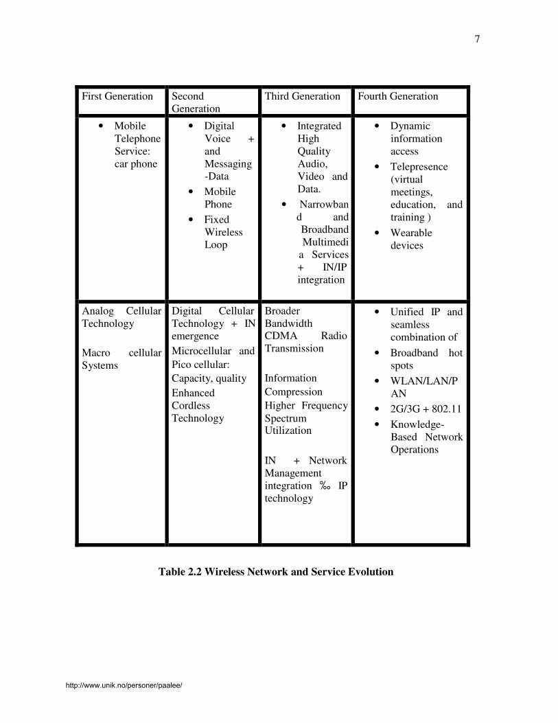
7
First Generation Second
Generation
Third Generation Fourth Generation
• Mobile
Telephone
Service:
car phone
• Digital
Voice +
and
Messaging -Data
• Mobile
Phone
• Fixed
Wireless
Loop
• Integrated
High
Quality
Audio,
Video and
Data.
• Narrowban
d and
Broadband
Multimedi
a Services
+ IN/IP
integration
• Dynamic
information
access
• Telepresence
(virtual
meetings,
education, and
training )
• Wearable
devices
Analog Cellular
Technology
Macro cellular
Systems
Digital Cellular
Technology + IN
emergence
Microcellular and
Pico cellular:
Capacity, quality
Enhanced
Cordless
Technology
Broader
Bandwidth CDMA Radio
Transmission
Information
Compression
Higher Frequency
Spectrum Utilization
IN + Network
Management
integration ‰ IP
technology
• Unified IP and
seamless
combination of
• Broadband hot
spots
• WLAN/LAN/P
AN
• 2G/3G + 802.11
• Knowledge-
Based Network
Operations
Table 2.2 Wireless Network and Service Evolution
http://www.unik.no/personer/paalee/

8
The history and evolution of mobile service from the 1G (first generation) to fourth
generation process began with the designs in the 1970s that have become known as 1G. Refer to
table 2.2 for an overview of the evolution of mobile service. The earliest systems were
implemented based on analog technology and the basic cellular structure of mobile
communication. These early systems solved many fundamental problems. The 2G systems
designed in the 1980s were still used mainly for voice applications but were based on digital
technology, including digital signal processing techniques. These 2G systems provided
circuit-switched data communication services at a low speed.
During 1990s, two organizations worked to define next, or 3G, mobile system, which
would eliminate previous incompatibilities and become a truly global system. The 3G system
would have higher quality voice channels, as well as broadband data capabilities, up to
2Mbps. An interim step is being taken between 2G and 3G, the 2.5G. It is basically an
enhancement of the two major 2G technologies to provide increased capacity on the 2G RF
(Radio Frequency) channels and to introduce higher throughput for data service, up to 384
kbps. A very important aspect of 2.5G is that the data channels are optimized for packet data,
which introduces access to the internet from mobile devices, whether telephone, PDA
(Personal digital assistant), or laptop. However, the demand for higher access speed
multimedia communication in today’s society, which greatly depends on computer
communication in d ig i t a l fo rm at , s eems unlimited.
Traditional phone networks (2G cellular networks) such as GSM, used mainly for
voice transmission, are essentially circuit-switched. 2.5G networks, such as GPRS, are an
extension of 2G networks, in that they use circuit switching for voice and packet switching
for data transmission. Circuit switched technology requires that the user be billed by airtime
http://www.unik.no/personer/paalee/

9
rather than the amount of data transmitted since that bandwidth is reserved for the user.
Packet switched technology utilizes bandwidth much more efficiently, allowing each user’s
packets to compete for available bandwidth, and billing users for the amount of data
transmitted. Thus a move towards using packet-switched, and therefore IP networks, is natural.
3G networks were proposed to eliminate many problems faced by 2G and 2.5 G
networks, like low speeds and incompatible technologies (TDMA/CDMA) in different
countries. Expectations for 3G included increased bandwidth: 128Kbps in a car and 2 Mbps
in fixed applications. In theory, 3G would work over North American as well as European
and Asian wireless air interfaces. In reality, the outlook for 3G is neither clear nor certain.
Part of the problem is that network providers in Europe and North America currently
maintain separate standards’ bodies. The standards’ bodies mirror differences in air interface
technologies. In addition there are financial questions as well that cast a doubt over 3G’s
desirability. There is a concern that in many countries, 3G will never be deployed. This
concern is grounded, in part, in the growing attraction of 4G wireless technologies.
A 4G or 4th
generation network, a new generation of wireless is intended to
complement and replace the 3G systems. Accessing information anywhere, anytime, with a
seamless connection to a wide range of information and services, and receiving a large
volume of information, data, pictures, video, and so on as shown is Figure 2.2 are the keys
of the 4G infrastructures.
http://www.unik.no/personer/paalee/

10
Figure 2.2 4G Visions [3]
The future 4G infrastructure [3] will consist of a set of various networks using IP as a
common protocol so that users are in control because they will be able to choose every
application and environment. A 4G or 4th
generation network is the name given to an IP-
based mobile system that provides access through a collection of radio interfaces. A 4G
network promises seamless roaming/handover and best connected service, combining
multiple radio access interfaces (such as WLAN, Bluetooth, GPRS) into a single network
that subscribers may use [12]. With this feature, users will have access to different services,
increased coverage, the convenience of a single device, one bill with reduced total access
cost, and more reliable wireless access even with the failure or loss of one or more networks.
4G was simply an initiative by R & D labs to move beyond the limitations, and
address the problems of 3G which was having trouble meeting its promised performance and
throughput. In the most general level, 4G architecture includes three basic areas of
connectivity: Personal Area Networking (such as Bluetooth), local high-speed access
points on the network including wireless LAN technologies, and cellular connectivity. 4G
http://www.unik.no/personer/paalee/

11
calls for a wide range of mobile devices that support global roaming. Each device will be
able to interact with Internet-based information that will be modified on the fly for the
network being used by the device at that moment. The roots of 4G lie in the idea of pervasive
computing [20]. The glue for all this is likely to be software defined radio (SDR) [13]. SDR
enables devices such as cell phones, PDAs, PCs and a whole range of other devices to scan
the airwaves for the best possible method of connectivity, at the best price. In an SDR
environment, functions that are formerly carried out solely in hardware – such as the
generation of the transmitted radio signal and the tuning of the received radio signal – are
performed by software [7]. Thus, the radio is programmable and able to transmit and
receive over a wide range of frequencies while emulating virtually any desired
transmission format. As the number of wireless subscribers rapidly increases guaranteeing
the quality of services anytime, anywhere, and by any-media becomes indispensable. These
services require various networks to be integrated into IP-based networks, which further
require a seamless vertical handoff to 4th
generation wireless networks. And as one of the
next generation mobile communications, the 4th
generation mobile communications
provides various services, such as high-speed data services and IP-based access to Radio
Access Network, etc. Various interface techniques such as WLAN, Bluetooth, UTMS,
and CDMA2000 are integrated into the IP-based networks as an overlay structure. In
this structure, the optimum services are provided to mobile hosts. Mobile hosts in this
structure can be connected to the network through various access points. Moreover, a seamless
handoff should also be supported between different air interface techniques during inter-
network movement.
http://www.unik.no/personer/paalee/

12
2.1 Features of 4G Networks
High Speed - 4G systems should offer a peak speed of more than 100Mbits per
second in stationary mode with an average of 20Mbits per second when travelling.
High Network Capacity – Should be at least 10 times that of 3G systems. This will
quicken the download time of a 10-Mbyte file to one second on 4G, from 200 seconds on 3G,
enabling high-definition video to stream to phones and create a virtual reality experience on
high-resolution handset screens.
Fast/Seamless handover across multiple networks – 4G wireless networks should support
global roaming across multiple wireless and mobile networks.
Next-generation multimedia support – The underlying network for 4G must be able to
support fast speed volume data transmission at a lower cost than today.
The goal of 4G [4] is to replace the current proliferation of core mobile networks with a
single worldwide core network standard, based on IP for control, video, packet data, and
voice. This will provide uniform video, voice, and data services to the mobile host, based
entirely in IP. The objective is to offer seamless multimedia services to users accessing an all
IP based infrastructure through heterogeneous access technologies. IP is assumed to act as an
adhesive for providing global connectivity and mobility among networks. An all IP-based 4G
wireless network has inherent advantages over its predecessors. It is compatible with, and
independent of the underlying radio access technology [4].
An IP wireless network replaces the old Signalling System 7 (SS7)
[6] telecommunications protocol, which is considered massively redundant. This is because
SS7 signal transmission consumes a larger part of network bandwidth even when there is
no signalling traffic for the simple reason that it uses a call setup mechanism to
http://www.unik.no/personer/paalee/

13
reserve bandwidth, rather time/frequency slots in the radio waves. IP networks, on the other
hand, are connectionless and use the slots only when they have data to send. Hence there is
optimum usage of the available bandwidth. Today, wireless communications are heavily biased
toward voice, even though studies indicate that growth in wireless data traffic is rising
exponentially relative to demand for voice traffic. Because an all IP core layer is easily
scalable, it is ideally suited to meet this challenge. The goal was a merged
data/voice/multimedia network.
2.2 Possible Architectures for 4G Networks
Accessing different mobile and wireless networks is one of the most challenging
problems to be faced in the deployment of 4G technology [22]. Figure 2.3 shows three
possible architectures:
• Using a multimode device
• An overlay network
• A common access protocol
http://www.unik.no/personer/paalee/

14
Figure 2.3 Possible Architectures for 4G Networks [22]
http://www.unik.no/personer/paalee/

15
2.2.1 Multimode Devices
To access services on different wireless networks, one single physical terminal with
multiple interfaces is used. Existing advanced mobile phone system on code division
multiple access dual function cell phone, dual function satellite cell phone and global system
for mobile telecommunications are examples of Multimode Device architecture. Call
completion can be improved and coverage area is expanded effectively using this
architecture. When there is network, link or switch failure, reliable wireless coverage should
be provided. The handoff between networks can be initiated by user, device or network.
There is no requirement of wireless network modification or employment of interworking
devices as the device itself incorporates most of the additional complexity. A database can be
deployed by each network which stores the information to keep track of user location, device
capabilities, network conditions and user preferences.
2.2.2 Overlay Network
There are several universal access points in overlay network with which a user can
access. A wireless network is selected by each universal access points based on availability,
quality of service specifications and user defined choices [8]. Protocol and frequency
translation, content adaptation is performed by universal access point on behalf of users. As
the user moves from one universal access point to another, rather than the user or the device,
handoffs are performed by overlay networks. User, network, device information, capabilities
and preferences are stored by the universal access point. Single billing and subscription is
supported as universal access points keep track of the various resources a caller uses.
http://www.unik.no/personer/paalee/
16
2.2.3 Common Access Protocol
Supporting one or two standard access protocols by wireless networks allows this
protocol to become viable. Using wireless asynchronous mode requires interworking
between different networks as one possible solution. Transmission of ATM cells with
additional headers or wireless ATM cells requiring changes in the wireless networks must be
allowed by every wireless network to implement wireless ATM. One protocol might be used
by one or more types of satellite based networks while another protocol is used by one or
more terrestrial wireless networks.
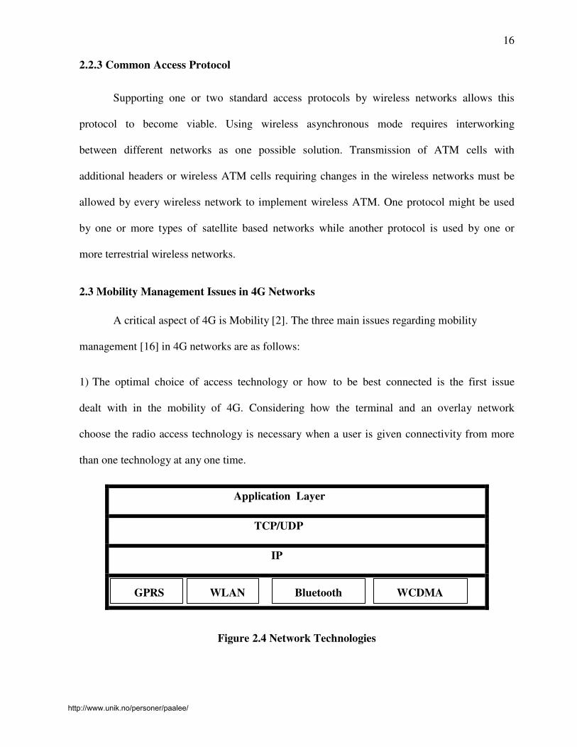
2.3 Mobility Management Issues in 4G Networks
A critical aspect of 4G is Mobility [2]. The three main issues regarding mobility
management [16] in 4G networks are as follows:
1) The optimal choice of access technology or how to be best connected is the first issue
dealt with in the mobility of 4G. Considering how the terminal and an overlay network
choose the radio access technology is necessary when a user is given connectivity from more
than one technology at any one time.
Application Layer
TCP/UDP
IP
GPRS WLAN Bluetooth WCDMA
Figure 2.4 Network Technologies
http://www.unik.no/personer/paalee/

17
There are several network technologies available today, which can be viewed as
complementary. For high data rate indoor coverage, WLAN is best suited. GPRS or UMTS
are best suited for nation wide coverage and can be regarded as wide area networks,
providing a higher degree of mobility. An optimal choice of radio access technology among
all those available should be made by the user of the mobile terminal or the network. The
network to be connected and when to perform a handover between different networks are
determined by a handover algorithm. Ideally, the handover algorithm would assure that the
best overall wireless link is chosen. The type of application being run by the user at the time
of handover should be taken into consideration during the network selection strategy. This
ensures stability as well as optimal bandwidth for interactive and background services.
2) The second issue regards the design of a mobility enabled IP networking architecture,
which contains the functionality to deal with mobility between access technologies.This
includes fast, seamless vertical (between heterogeneous technologies) handovers (IP micro-
mobility), quality of service (QoS), security and accounting. Real-time applications in the
future will require fast/seamless handovers for smooth operation. Mobility in IPv6 [15] is not
optimised to take advantage of specific mechanisms that may be deployed in different
administrative domains. Instead, IPv6 provides mobility in a manner that resembles only
simple portability. To enhance mobility in IPv6, ‘micro-mobility’ protocols, Cellular IP and
Hierarchical Mobile IPv6 [5] have been developed for seamless handovers i.e.; handover that
result minimal handover delay, minimal packet loss, and minimal loss of communication
state.
3) The adaptation of multimedia transmission across 4G networks is the third and the last
issue. As multimedia is the main service feature of 4G networks, and changing radio access
networks may in particular result in drastic changes in the network changes. Thus the
http://www.unik.no/personer/paalee/

18
framework for multimedia transmission must be adaptive. In cellular networks such as
UMTS, users compete for scarce and expensive bandwidth. Variable bit rate services provide a
way to ensure service provisioning at lower costs. In addition the radio environment has
dynamics that renders it difficult to provide a guaranteed network service. This required that
the services are adaptive and robust against varying radio conditions. High variations in the
network Quality of Service [18] leads to significant variations of the multimedia quality.
The result could sometimes be unacceptable to the users. Avoiding this requires choosing
an adaptive encoding framework for multimedia transmission. The network should signal
QoS variations to allow the application to be aware in real time of the network conditions.
User interactions will help to ensure personalised adaptation of the multimedia presentation.
Wireless Mobile Networks has Mobility Management as an integral function.
Mobility Management influences the type and quality of Wireless Network service offerings.
Each generation of Wireless Mobile Network has different mechanisms for Mobility
Management. Network support of subscriber mobility requires registration, authentication,
paging, roaming, radio resource management and excess channel capacity. Mobility
Management focuses on the network’s ability to allocate radio access network resources.
http://www.unik.no/personer/paalee/

19
3. Challenges in 4G Networks
4G Networks are all IP based heterogeneous networks that allow users to use any
system at anytime and anywhere. Users carrying any integrated terminal can use a wide
range of applications provided by multiple wireless networks. 4G systems provide not only
telecommunications services, but also a data-rate service when good system reliability is
provided. At the same time, a low per-bit transmission cost is maintained. Users can use
multiple services from any provider at the same time. Imagine a 4G mobile user who is
looking for information on movies shown in nearby cinemas. The mobile may
simultaneously connect to different wireless systems. These wireless systems may include
Global Positioning System (GPS) (for tracking users current location), a wireless LAN (for
receiving previews of the movies in nearby cinemas), and a code-division multiple access
(for making a telephone call to one of the cinemas). In this example, the user is actually using
multiple wireless services that differ in quality of service (QoS) levels [18], security
policies, device settings, charging methods, and applications. There are number of challenges
faced by 4G networks in integrating all the services.
3.1 An overview of challenges in Integrating Heterogeneous Systems
The challenges mentioned in the above table are grouped into three different aspects:
• Mobile Station
• System
• Service
http://www.unik.no/personer/paalee/

20
3.1.1 Mobile Station
To use large variety of services and wireless networks in 4G systems, multimode user
terminals are essential as they can adapt to different wireless networks by
reconFigureuring themselves. The need to use multiple terminals is eliminated. Adapting
software radio approach is the most promising way of implementing multimode user
terminals [14]. The analog part of the receiver consists of an antenna, a bandpass filter,
and a low noise amplifier. The received analog signal is digitized by the analog/digital
converter immediately after the analog processing. The processing in the next stage is
then performed by a reprogrammable baseband digital signal processor. The digital signal
processor will process the digitized signal in accordance with the wireless environment.
Unfortunately, the current software radio technology is not completely feasible for all the
different wireless networks due to the following technological problems. It is impossible to
have one antenna and one low noise amplifier to serve the wide range of frequency bands.
Using multiple analog parts to work in different frequency bands is the only solution. The
design complexity and physical size of a terminal are increased. And existing analog/digital
converters are not fast enough.
3.1.2 System
For 4G infrastructure to provide wireless services at any time and anywhere, terminal
mobility is a must. Terminal mobility allows mobile clients to roam across geographic
boundaries of wireless networks. The two main issues in terminal mobility are location
management and handoff management. The system tracks and locates a mobile terminal for
possible connection. Location management involves handling all the information about the
roaming terminals, such as original and current located cells, authentication information, and
http://www.unik.no/personer/paalee/

21
QoS capabilities. Handoff Management maintains ongoing communication when the terminal
roams. Mobile IPv6 is a standardized IP-based mobility protocol for IPv6 wireless systems.
Each terminal has an IPv6 home address. Whenever the terminal moves outside the local
network, the home address becomes invalid, and the terminal obtains a new IPv6 address
called care-of address in the visited network. A binding between the terminal’s home address
and care-of address is updated to its home agent in order to support continuous
communications. This kind of handoff process causes an increase in system load, high
handover latency, and packet losses. It is hard to decide the correct handoff time because
measuring handoffs among different wireless systems is very complicated. The uncertain
handoff completion time adds to the complexity in designing good handoff mechanisms.
3.1.3 Services
More comprehensive billing and accounting systems are needed, with the increase of
service varieties in 4G systems. Customers may subscribe to many services from a number of
service providers at the same time rather than only one operator. Dealing with multiple
service providers might be inconvenient for customers. Operators need to design new
business architecture, accounting processes, and accounting data maintenance. It is
challenging to formulate one single billing method that covers all the billing schemes
involved. 4G networks support multimedia communications, which consists of different
media components with possibly different charging units. This adds difficulty to the task of
designing a good charging scheme for all customers. The media components may have
different QoS requirements. To decide a good tariff for all possible components is very
complicated. To build a structural billing system for 4G, several frameworks have been
studied [21].
http://www.unik.no/personer/paalee/

22
4. Handoff in Networks
The services provided by the public switched telephone networks (PSTN) [23] are
leveraged by wireless mobile telephone network of public land mobile networks (PLMN).
PSTNs ate backbones to PLMNs. Infrastructure for wireless access, mobility management
and external network gateways are provided by the network elements of PLMNs.
A simple PLMN [23] consists of the following components:
• Base stations
• Mobile switching service centres (MSC)
• Home Location Register (HLR)
• Visitor Location Registers (VLR)
• Authentication Centre (AUC)
• Equipment Identification Register (EIR).
Figure 4.1 Simple PLMN [23]
http://www.unik.no/personer/paalee/

23
Radio interface for mobile subscribers are used to provide network access by the base
stations. Managing base stations, consulting PLMN database to establish subscriber access
rights, routing mobile traffic is managed by MSC. MSC also serves as a gateway to external
networks. Subscriber profiles, location encryption codes and equipment data are stored in
PLMN databases. HLR, VLR, AVC and EIR are PLMN databases.
All telephone networks require fundamental services like Call establishment and
connection maintenance. Call initiation signalling, connection path establishment, alerting
called party, call acceptance and preservation of connection until end of session signalling is
detected consists of the PSTN call process for two authorized fixed location subscribers. The
PSTN uses the fixed location of the subscriber to simplify network functions. Authentication,
call establishment and call preservation are simplified by fixed subscriber location.
Subscriber mobility significantly complicates network operations, although a PLMN call
process performs the same functions of a PSTN.
PLMNs must implement mobility management technologies to provide PSTN
services. These technologies enable PLMNs to establish and maintain calls to authorized
mobile subscriber. Mobility Management uses the HLR, VLRs, MSCs and Base Stations.
Call quality, reliability and availability are strongly influenced by Mobility Management
technologies. Mobility Management is the ability of a PLMN to orchestrate calls for its
subscribers and radio management maintains the call regardless of the mobility of the
subscribers. PLMNs must track and dynamically route calls to its subscribers in a transparent
fashion. The main functions of mobility management are locating, authenticating and
tracking mobile subscribers. PLMNs use a registration process to report a mobile station’s
right to access network services. Roaming allows authorized mobile subscribers to use
networks other than their home PLMN. Signal quality assessments, base station selection and
http://www.unik.no/personer/paalee/
24
switching constitute Radio Resource Management (RRM).
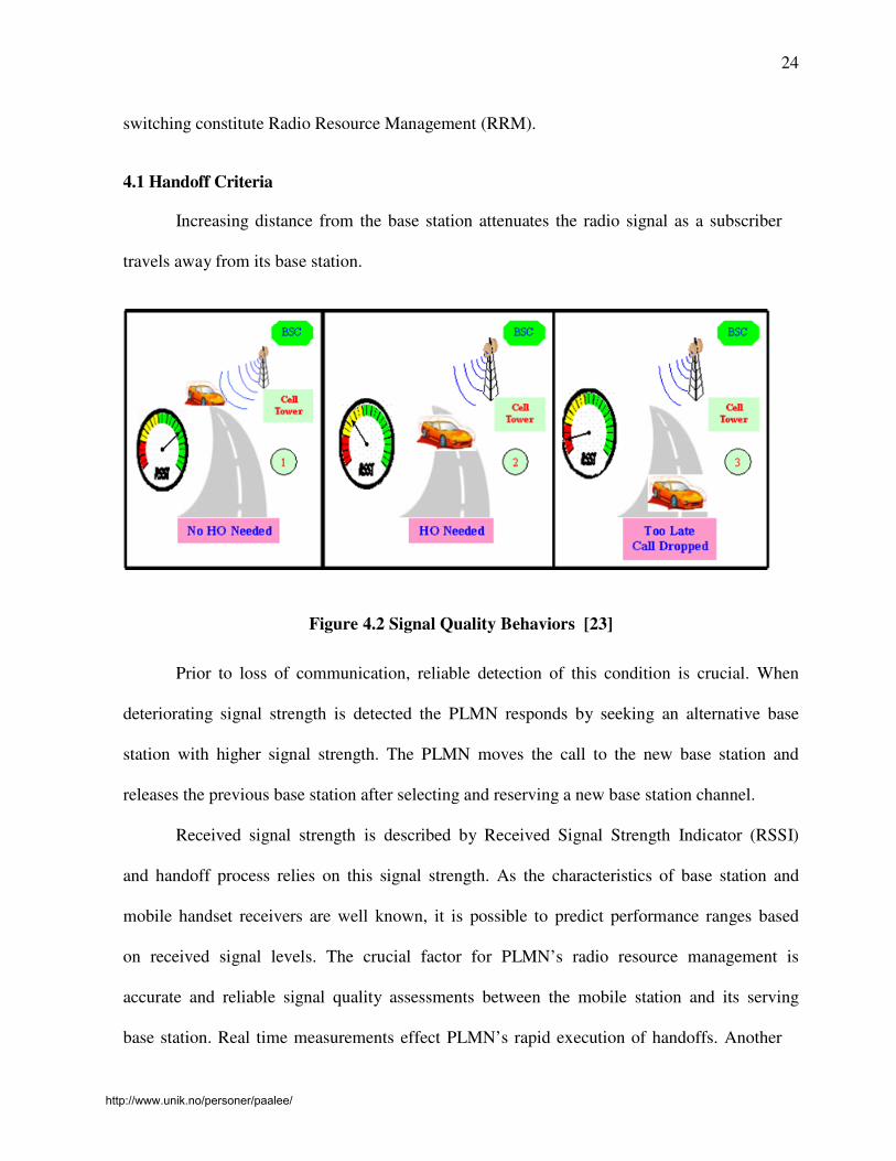
4.1 Handoff Criteria
Increasing distance from the base station attenuates the radio signal as a subscriber
travels away from its base station.
Figure 4.2 Signal Quality Behaviors [23]
Prior to loss of communication, reliable detection of this condition is crucial. When
deteriorating signal strength is detected the PLMN responds by seeking an alternative base
station with higher signal strength. The PLMN moves the call to the new base station and
releases the previous base station after selecting and reserving a new base station channel.
Received signal strength is described by Received Signal Strength Indicator (RSSI)
and handoff process relies on this signal strength. As the characteristics of base station and
mobile handset receivers are well known, it is possible to predict performance ranges based
on received signal levels. The crucial factor for PLMN’s radio resource management is
accurate and reliable signal quality assessments between the mobile station and its serving
base station. Real time measurements effect PLMN’s rapid execution of handoffs. Another
http://www.unik.no/personer/paalee/

25
key parameter for radio resource management is the reference point of signal strength
measurements. The PLMN can use measurements made at the base station, handset or both
as a reference for resource switching decisions.
4.2 Handoff Strategies
An event when a mobile station moves from one wireless cell to another is called
Handoff. Handoff can be of two types: horizontal (intra-system) and vertical (inter-system)
cases. Handoff within the same wireless access network technology is considered as
Horizontal handoff, and handoff among heterogeneous wireless access network technologies is
considered vertical handoff. The terminology of horizontal and vertical reflects the
wireless access network technology instead of the administrative domain in comparison to
macro- and micro mobility. There are different subclasses such as follows:
• Vertical macro mobility refers to mobility among different administrative domains
using different wireless technologies
• Horizontal macro mobility refers to mobility among different administrative domains
using the same wireless technology
• Vertical micro mobility refers to mobility within the same administrative domain
using different wireless technologies
• Horizontal micro mobility refers to mobility within the same administrative domain
using the same wireless technology.
4.3 Handoff Methods
Handoffs have several methods and they are technology dependent. The two main
handoff methods are:
http://www.unik.no/personer/paalee/
26
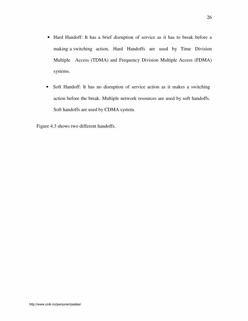
• Hard Handoff: It has a brief disruption of service as it has to break before a
making a switching action. Hard Handoffs are used by Time Division
Multiple Access (TDMA) and Frequency Division Multiple Access (FDMA)
systems.
• Soft Handoff: It has no disruption of service action as it makes a switching
action before the break. Multiple network resources are used by soft handoffs.
Soft handoffs are used by CDMA system.
Figure 4.3 shows two different handoffs.
http://www.unik.no/personer/paalee/

27
Figure 4.3 Handoff Methods [23]
4.4 Handoff Scenarios
As mobiles traverse cell or sector boundaries, majority of handoffs support calls. The
following are scenarios where Handoff processes are required:
• Intra-MSC - Involve crossing cell boundaries within a MSC’s service area
• Inter-MSC - Involves crossing cell boundaries between MSCs
http://www.unik.no/personer/paalee/

28
• Roaming - Involves crossing cell boundaries between different network
operators
• Intra-cell – Involves crossing sector boundaries within a cell
• Switching channels to circumvent persistent interference
Figure 4.4 Basic Handoff Scenarios [23]
4.5 Horizontal Handoff
A Horizontal handoff is a handoff between two network access points that use the
same network technology and interface. For example, when a mobile device moves in and
out of various 802.11b network domains, the handoff activities would be considered as a
horizontal handoff, since connection is disrupted solely by device mobility.
4.6 Vertical Handoff
A Vertical handoff is a handoff between two network access points, which are using
different connection technologies. For example, when mobile device moves out an 802.11b
http://www.unik.no/personer/paalee/

29
network into a GPRS network, the handoff would be considered a vertical handoff.
4.7 Support for Vertical Handoffs
The current IPv6 [17] specification does not support vertical handoffs. Since IP is
the common protocol, everything below it is abstracted from the application. For the
application, it is always connected as handoffs occur. To provide this support in IPv6 a
daemon can be run at the network layer which takes care of switching between different
radio accesses technologies. The mobile device might be having separate interface cards
for each of the networks or may use a single multimode card which works in different
modes at different times. The protocol stacks of each of the different radio access technology
are stored in the mobile device. The daemon in the network layer will then choose
which radio access network (RAN) to use on the basis of network speed, quality of service,
cost of usage and other similar criteria. The selection policies are customizable and changes
between different RANs are automatic and transparent to the user and depend on coverage
and network load conditions. After selecting the RAN, the daemon then initializes the
appropriate protocol stack before starting to use that interface. This way the IP datagrams
being passed down get encapsulated in the correct format of the radio access technology in
use. This model allows the device to utilize any interface as long as the hardware is present
by just installing the necessary stack protocols.
A seamless handoff should also be supported between different air interface
techniques during inter-network movement. This type of handoff is called a vertical handoff,
because the mobile is moving to another network (heterogeneous network) which has a
different air interface technique. Various wireless LAN services are being introduced in
hotspot areas such as campuses, hotels and offices. IEEE802.11 WLAN services having high
http://www.unik.no/personer/paalee/

30
bandwidth are used to cover limited hotspot areas. If the mobile host (MH) goes out of the
hotspot coverage, the call will be dropped. In the 4th
generation, a WLAN cell is overlaid
within a CDMA2000 cell that is constructed into an ALL-IP based network. A seamless
handoff is supplied through the vertical handoff process even if the MH goes out of the
WLAN coverage area. The minimised cell size in 4th
generation networks results in frequent
handoffs.
Recently proposed network architecture and procedure for the vertical handoff [24]
adopts the mobility management concept through the Mobile Agent (MA) and Subnet Agent
(SA) functions to minimize the delay during vertical handoff. The first goal of seamless
handoff is low handoff latency, power saving, and low bandwidth overhead [8]. WLAN and
CDMA 2000 networks have different frequency, maximum data speed and cost
characteristics. The time for the handoff procedure to begin in the handoff region is decided
by the handoff delay time and throughput according to traffic characteristics. The real-time
traffic preferentially takes into account the handoff delay, and the non-real time traffic takes
the throughput into account.
Methods for interconnecting CDMA2000 networks with heterogeneous air interfaces
and WLAN use emulators, virtual access points, or mobile IP. Mobile IP [9] method is
operated peer-to-peer relationship that shows better performance than the previous two
methods that operate in master/slave relationship. An IP-based architecture using mobile IP
is shown in Figure 4.5
http://www.unik.no/personer/paalee/

31
Figure 4.5 WLAN-CDMA Cellular Interconnection Architecture based on IP [24]
In the WLAN-CDMA Cellular Interconnection architecture [24], handoff occurs in the
following cases:
• Mobile Download
• Mobile Upward
• Mobile Through
Mobile Download
When the mobile host serviced in the WLAN region moves to another area and is
synchronized to the CDMA network Mobile Download occurs.
Mobile Upward
When the Mobile Host enters into a WLAN from the cellular network outside the
WLAN, mobile upward occurs.
http://www.unik.no/personer/paalee/

32
Mobile Through
When one of the two networks in the media selection layer is selected, Mobile
Through occurs.
Figure 4.6 Mobile Host Protocol STACK [24]
The mobile host saves power by operating only one interface card when operating in
the handoff transition region before it goes into the handoff transition region. The mobile
host after moving into the transition region then activates the interface card for the neighbors.
http://www.unik.no/personer/paalee/

33
5. Vertical Handoff Procedure and Algorithm between IEEE802.11
WLAN and CDMA cellular network
A seamless vertical handoff procedure [24] between IEEE802.11 WLAN and
CDMA2000 cellular network that overlays the WLAN and also covers a larger area is
discussed in this chapter. The traffic is classified into real-time and non real-time services in
this algorithm. The architecture adopts the mobility management concept through the Mobile
Agent and the Subnet Agent functions to minimize the delay during vertical handoff. MD
Handoff involves the process in which mobile host leaves the WLAN service area and
connects to the CDMA cellular network. The strength of the beacon signal weakens as the
Mobile Host moves away from the WLAN access point. The signal strength is compared
with the threshold value and if the signal strength value goes below the threshold value, then
the CDMA Cellular card is activated and the MH moves into the CDMA from WLAN
resulting in the handoff.
When an Agent Advertisement message is received from the Cellular subnet
agent, the MH sends a Handoff Ready Request message to the MA through the required
access point. A subnet agent of the cellular network is configured with the overlay network
that buffers the received packets. The MA sends incoming packets to the subnet agent. The
subnet agent in turn receives a Registration message and will start sending the buffered
packets. Buffering is done in order to save the in bound packets during the handoff
period.
The handoff algorithm is executed when the beacon signals are below the threshold
value. A Route Update message is sent by the MA after the handoff to the base station to
request traffic channel allocation [19]. Registration to the SA and MA is performed. As soon
http://www.unik.no/personer/paalee/
34
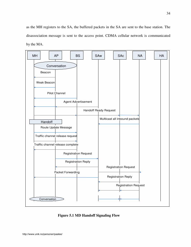
as the MH registers to the SA, the buffered packets in the SA are sent to the base station. The
disassociation message is sent to the access point. CDMA cellular network is communicated
by the MA.
MH AP BS SAw SAc NA HA
Conversation
Beacon
Weak Beacon
Pilot Channel
Agent Advertisement
Handoff Ready Request
Handoff
Route Update Message
Multicast all inbound packets
Traffic channel release request
Traffic channel release complete
Registration Request
Registration Reply
Packet Forwarding
Registration Request Registration Reply
Registration Request
Conversation
Figure 5.1 MD Handoff Signaling Flow
http://www.unik.no/personer/paalee/

35
When the MH serving in the CDMA cellular network region enters the WLAN service
region, it connects to the WLAN. This is called the MU handoff. The Figure 5.2 shows the
signalling flow:
Figure 5.2 MU Handoff Signaling flow
http://www.unik.no/personer/paalee/

36
Power saving can be achieved in this case by determining the time of the checking
beacon signal in the handoff transition region, and the time to activate the WLAN card in the
MH. For example, position information can be used. For the seamless handoff service, the
handoff point in the MU is not a critical factor, because the cellular network covers the
WLAN region with an overlay network.
In the Figure5.2, the MH receives a beacon signal from the AP through activating the
WLAN card. If the MH receives an Agent Advertisement message from the SA, it sends a
Handoff Ready Request message to the MA through the currently serving cellular network.
Then the MA transmits in-bound packets to the SA of the WLAN. After that, the MH checks
the received beacon signals continuously to determine whether to handoff or not. If the
conditions for the handoff are satisfied, then the handoff procedure is performed. The MH
requests the release of the channel that is allocated to the CDMA cellular network and
transmits a Reassociation Request message to the AP in the WLAN. From now on, the MH
communicates with the WLAN network.
5.1 Handoff Algorithm and Analysis
There are many differences between the radio link characteristics of the WLAN and
the CDMA Cellular networks. Hot spot areas, such as campuses, hotels, and restaurants are
covered by WLAN at low cost and high data rate. However, CDMA cellular networks serve a
wider area than WLAN at a higher cost and lower data rate. The following tables show the
coverage, cost and data rate of WLAN and CDMA.
http://www.unik.no/personer/paalee/

37
RA Coverage Data Rate Cost
AP Limited 1 – 11 Mbps Low
BSS Unlimited 9.6 – 300 Kbps High
Table 5.1 Specifications of AP and BSS
Conversational
Class
Streaming
Class
Interactive
Class
Background
Class
BER 10-3 10
-5 10-8 10
-9
Delay Strict and low Bounded Tolerable Unbounded
Guaranteed
Rate
Yes Yes No No
Application Voice, Internet
Game
VOD,Cable
TV
Web, Telnet FTP, E-mail
Table 5.2 Application Traffics
Depending on the delay sensitivity characteristics application traffics [10] are further
classified into two groups. Conversation and streaming classes that are sensitive to delay are
classified as real-time services. The loads in both the networks are assumed to be nominal. In
such case, there is a tradeoff between the handoff delay and throughput during those handoff
operations, which occur between networks whose radio links have different characteristics.
In the case of delay sensitive real-time services, handoff should be performed as
rapid as possible in order to minimize the delay due to frequent handoffs. For non real-time
service, the amount of transmission data is more important than the delay, and
http://www.unik.no/personer/paalee/

38
therefore, the connection to the WLAN should be maintained as long as possible. The
proposed Vertical handoff algorithm between WLAN and CDMA cellular networks is shown in
Figure5.3: [24]
Figure 5.3 Handoff algorithm between WLAN and CDMA [24]
The following variables are used to determine the vertical handoff [11]:
λ thresh : Predefined threshold value when the handoff transition region begins
λ : The number of continuous beacon signals that are received from the WLAN with the below
λ thresh
http://www.unik.no/personer/paalee/

39
λr : λ for real time service
λu : λ for mobile upward
λn : λ for non-real-time service
The relationship among the variables is as follows:
λr << λn << λu ------------------------------------------ (1)
5.2 Control Mechanism of Handoff
In real-time service, the handoff delay must be short in the handoff transition
region, therefore the number of continuous beacon signal should be lower than that of the non
real- time service in order to reduce handoff delay. Since the CDMA cellular network
covers a wide area and the handoff time is not critical for the MU, the value of λn should be
higher than other values. To reduce overall handoff delay, the in-bound packets are
multicasted to the SA of the target network by mobility management. They are multicasted
when the beacon signal strength in the MD falls below the λ thresh or rises higher than the
λthresh in MU. The multicasted data are buffered in the SA. These buffered data will be
transmitted to the BS if the MH is handed off to the target network before the timer expires.
Otherwise, those data will be discarded. During the periodic the MH checks of the RSS of
the received beacon signals, if the RSS falls below λ thresh, λ is increased by one. The MH
determines whether the handoff should take place or not by comparing λr, λn with the increased
λ. The control mechanism of the handoff is shown in Figure5.4.
http://www.unik.no/personer/paalee/

40
Figure 5.4 Control Mechanism of Handoff
First, the service classifier classifies the traffic as either real-time service, and
then it sends the control signal to the handoff decision block and the measurement block.
The power strength of the beacon signal in the transition region as the MH moves from
the coverage of the WLAN to outside coverage shown in Figure5.5 [11]:
Figure 5.5 Transition Region
The following variables are used to deduce handoff delay and throughput as the MH
moves around the handoff transition region.
Tt : Region extending from the point at which the power P falls below λ thresh for the first time permanently.
T1 : Each contiguous stretch of time where P > λ thresh within Tt
http://www.unik.no/personer/paalee/

41
T2 : Each contiguous stretch of time where P < λ thresh within Tt
TN : Normalized handoff delay in handoff transition region
S(i) : Average throughput in each case
N : Number of times P crosses the value of
∆ : Handoff Completion time
R1 : Effective data rate available over the air in the WLAN
R2 : Effective data rate available over the air in the CDMA Cellular Network.
http://www.unik.no/personer/paalee/

42
6. Simulation and Implementation of Handoff algorithm
In this chapter we describe how the Vertical Handoff Algorithm was implemented
and how the simulation was carried out. It is important that we test the performance of the
algorithm by simulating it over a wide range of simulation parameters. This is true not only
for the Vertical Handoff Algorithm but as a matter of fact, for any algorithm. Simulation
firstly, helps us determine whether the algorithm is performing correctly as required by the
standards and the user. Before the algorithm is implemented in real time systems, its
performance has to be carefully studied so that, the system in which the algorithm is
implemented performs according to the users expectations.
Secondly, this simulation also helps us determine the right values of the parameters
that need to be set so that the algorithm attains a satisfactory performance level. If the
parameters are not appropriately set then it may happen that the algorithm might be
switching too often between the two networks without any real necessity for doing it and
thus, causing a sub-optimal performance of the system/device; or it might also happen
that the algorithm does not switch the device connection between networks even though
the device might perform better in the other network.
Thus, it is very important that we test the algorithm using simulation in order to
determine its effectiveness when used in real world devices and to find the right parametersof
the algorithm so that its performance is optimized. We start off this chapter by describing the
code and the inputs required and how the code operates. In the next section we present some
results and analyze the plots so obtained. Finally, we present the conclusions drawn from our
simulation study.
http://www.unik.no/personer/paalee/

43
6.1 Code Structure and Description
The code structure shown in Figure6.1 is self explanatory, but for the sake of clarity it is
elaborated in this section. Refer Appendix A for Code. The code requires a set of input
values for the parameters (Appendix B), for example, the value of “threshold signal”, which is
the value of signal strength. Any signal having strength less than this threshold value is
considered weak and any signal having strength greater than the threshold value is
considered as strong. We can also choose to set the user in any of the networks at the start of
the simulation. Obviously in real world whether the user is working in a network is
determined by the position of the user or the position of his device to be more precise. Also
simulation is carried on for a specific period of time. For speeding up the simulation process,
time has been converted to number of iterations. At the start of any iteration the signal
strength is measured.
If the user is working in WLAN at the start of the simulation, the simulation is carried
out as described below. The signal strength is determined by randomly generating a value
that lies between a predetermined lower and upper bounds that are to be set by us. Once the
signal strength is determined we need to determine whether the user is working in real-time
or non real-time. This is done by randomly generating either 0 or 1 with equal probability. If
the user works in real time then it might be better if the user receives strong signals more
frequently than while working in non real-time. Once we determine whether the user works in
real-time or non real-time, we measure the number of times the user/device receives a
weak signal. If the weak signal frequency exceeds a preset value the user/device will be
connected to CDMA network. If during any process the user/device receives a strong signal
the weak signal count will be reset and the user continues to operate in WLAN network.
http://www.unik.no/personer/paalee/

44
Refer Appendix C for sample results.
Figure 6.1 Structure of the C code that runs the Simulation
http://www.unik.no/personer/paalee/

45
If the user starts working in CDMA, we first need to determine whether the user is
near a WLAN network or not before measuring the signal strength. In real-time we incur
some cost in terms of system/device resource utilization each time we measure the signal
strength, so we do not want to waste the resources of the device to measure the signal
strength unnecessarily and hence we measure the signal strength only if the user/device is
near WLAN network. If the user is not anywhere near WLAN network then obviously there is
no point for him to try and connect to the WLAN as he will be receiving a weak signal, and
hence the user/device will continue to work in CDMA in this case.
In case the user is working near WLAN we measure the strength of the signal and if
the strength exceeds the threshold value, the user/device is receiving a strong signal, so we
increase our strong signal count. If the strong signal count exceeds a preset value, we switch
over to WLAN since the user/device is reliably receiving a strong signal and it would be
sub-optimal to be still working in CDMA. If the strong signal count does not exceed we go
back to simulation point where we start off working in CDMA network.
In addition to determining all the parameters that are described above, it is
also of utmost importance that we determine a right value for the interval in which we
measure the signal strength. If we measure the signal strength too often we might be over
utilizing the system/device resources just for executing the Vertical Handoff Algorithm. If
we do not measure the signal strength for long durations of time, the user/device might
continue to work in a network where it would be very inefficient for it even though it might be
optimal to work in an alternative network.
http://www.unik.no/personer/paalee/

46
6.2 Results
In this section we will describe and analyze the results. We have t e s t ed the
performance of the algorithm over a varied range of simulation parameters. We present some
of the results in the plots below and analyze each plot individually.
In the plot shown in Figure6.2, we have plotted the threshold value of the signal strength
against the time spent in WLAN network. It shows that as the threshold value increases the
time spent in WLAN decreases. This is because the user/device criterion for a strong signal
increases, forcing most of the signal strength measurements to be weak and hence the user
switches to CDMA and spends more time in CDMA network. We find an anomaly when the
threshold value is 30, this is because our simulation is multi parameter based and affects
other parameters shows up at this particular signal strength.
λ thresh (vs) Time Spent in W LAN
120
100
80
Chi_Threshold (vs) 60
Time Spent in W LAN
40
20
0
0 5 10 15 20 25 35 40
λ thresh
Figure 6.2 Plot of λ thresh (vs) Time Spent in WLAN
In the plot shown in Figure6.3, we have plotted the threshold value of the signal strength
against the time spent in CDMA network. It shows that as the threshold value increases the
http://www.unik.no/personer/paalee/

47
time spent in CDMA increases. This is because the user/device criterion for a strong signal
increases, forcing most of the signal strength measurements to be weak and hence the user
switches to CDMA and spends more time in CDMA network. We find an anomaly when the
threshold value is 30, this is because our simulation is multi parameter based and the effect
other parameters shows up at this particular signal strength.
λ thresh (vs) Time Spent in CDMA
120
100
80
60 Chi_Threshold (vs)
Time Spent in CDMA
40
20
0
0 5 10 15 20 25 35 40
λ thresh
Figure 6.3 Plot of λ thresh (vs) Time Spent in CDMA
In the plot shown in Figure 6.4, we have plotted the value of weak signal count if
operating in real time required for switching to CDMA network (λr ) against the time spent in
WLAN network. The plot shows that as this value increases the time spent in WLAN
decreases. This is because the user/device count for weak signals easily exceeds λr value and
hence the user switches to CDMA network. This result also depends on the interactions of
other parameters as well, for example, if the threshold value had been low then the user
would be forced to switch a number of times between CDMA and WLAN networks, thus
spending almost the same amount of time in each network.
http://www.unik.no/personer/paalee/

48
λr (vs) Time Spent in W LAN
120
100
80
60 Lambda_r (vs) Time
Spent in W LAN
40
20
0
1 2 4 6 8 10 12 14
λ r
Figure 6.4 Plot of λr (vs) Time Spent in WLAN
In the plot shown in Figure6.5, we have plotted the value of strong signal count required
for switching to WLAN network (λu) against the time spent in WLAN network. The plot
shows that as this value increases the time spent in WLAN decreases. This is because the
user/device count for strong signals is difficult to exceed λu value and hence the user
continues to operate in CDMA network. This result also depends on the interactions of other
parameters as well, for example, if the threshold value had been low then the user would be
forced to switch a number of times between CDMA and WLAN networks, thus spending
almost the same amount of time in each network.
http://www.unik.no/personer/paalee/

49
λu(vs) Time Spent in WLAN
120
100
80
Lamda_u (vs) Time 60 Spent in W LAN
40
20
0
1 2 4 6 8 10 12 14
λ u
Figure 6.5 Plot of λu (vs) Time Spent in WLAN
In the plot shown in Figure 6.6, we have plotted the value of weak signal count if
operating in non real time required for switching to CDMA network (λn) against the time
spent in WLAN network. The plot shows that as this value increases the time spent in
WLAN decreases. This is because the user/device count for weak signals easily exceeds λn
value and hence the user switches to CDMA network. This result also depends on the
interactions of other parameters as well, for example, if the threshold value had been low
then the user would be forced to switch a number of times between CDMA and WLAN
networks, thus spending almost the same amount of time in each network.
http://www.unik.no/personer/paalee/

50
λn (vs) Time Spent in W LAN
120
100
80
60 Lambda_n (vs) Time
Spent in W LAN
40
20
0
1 2 4 6 8 10 12 14
λ n
Figure 6.6 Plot of λn (vs) Time Spent in WLAN
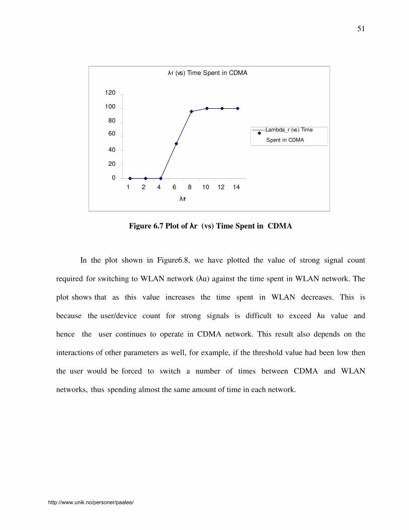
In the plot shown in Figure6.7, we have plotted the value of weak signal count if
operating in real time required for switching to CDMA network (λr) against the time spent
in WLAN network. The plot shows that as this value increases the time spent in WLAN
decreases. This is because the user/device count for weak signals easily exceeds λr value and
hence the user switches to CDMA network. This result also depends on the interactions of
other parameters as well, for example, if the threshold value had been low then the user
would be forced to switch a number of times between CDMA and WLAN networks, thus
spending almost the same amount of time in each network.
http://www.unik.no/personer/paalee/
51
λr (vs) Time Spent in CDMA
120
100
80
60 Lambda_r (vs) Time
Spent in CDMA
40
20
0
1 2 4 6 8 10 12 14
λ r
Figure 6.7 Plot of λr (vs) Time Spent in CDMA
In the plot shown in Figure6.8, we have plotted the value of strong signal count
required for switching to WLAN network (λu) against the time spent in WLAN network. The
plot shows that as this value increases the time spent in WLAN decreases. This is
because the user/device count for strong signals is difficult to exceed λu value and
hence the user continues to operate in CDMA network. This result also depends on the
interactions of other parameters as well, for example, if the threshold value had been low then
the user would be forced to switch a number of times between CDMA and WLAN
networks, thus spending almost the same amount of time in each network.
http://www.unik.no/personer/paalee/

52
λu (vs) Time Spent in CDMA
120
100
80
60 Lambda_u (vs) Time
Spent in CDMA
40
20
0
1 2 4 6 8 10 12 14
λ u
Figure 6.8 Plot of λu (vs) Time Spent in CDMA
In the plot shown in Figure6.6, we have plotted the value of weak signal count if
operating in non real time required for switching to CDMA network (λn) against the time spent
in WLAN network. The plot shows that as this value increases the time spent in WLAN
decreases. This is because the user/device count for weak signals easily exceeds λn value and
hence the user switches to CDMA network. This result also depends on the interactions of
other parameters as well, for example, if the threshold value had been low then the user
would be forced to switch a number of times between CDMA and WLAN networks, thus
spending almost the same amount of time in each network.
http://www.unik.no/personer/paalee/

53
λn (vs ) Tim e Spent in CDMA
120
100
80
Lam bda_n (vs )
60 Tim e Spent in CDMA
40
20
0
1 2 4 6 8 10 12 14
λn
Figure 6.9 Plot of λn (vs) Time Spent in CDMA
http://www.unik.no/personer/paalee/

54
7. Conclusion
An implementation of a seamless vertical handoff procedure and the effective handoff
algorithm for the handoff transition region between the WLAN and CDMA cellular network is
presented. In chapter 6, we have gone extensively about the various parameters that govern the
smooth functioning of the algorithm and how they affect the time spent in WLAN and
CDMA networks. The algorithm, as shown by the simulation results, does not result in too
many switches between the WLAN and CDMA networks and hence would provide quite a
useful tool for the device in real time functioning.
Nevertheless the algorithm has some drawbacks. One major drawback is that if the
parameters are not chosen rightly the algorithm would result in an inefficient usage of resources
and a sub-optimal performance of the device into which the algorithm is loaded. Second
drawback, which can be considered as an extension of the first one, is that if that the
algorithm might reset the strong or weak signal counts just before they reach their maximum
limit and thus resulting in the user operating in an inefficient network. A more robust
algorithm would also consider the number of times this reset has taken place and would
correspondingly switch between the networks. But in spite of these drawbacks if the
parameters are chosen correctly the algorithm can perform quite efficiently and a
maximum performance can be extracted from the device given an operating environment.
Mobility management using MA and SA was also adopted to minimize the handoff
delay in the WLAN-CDMA Cellular interconnection architecture based on IP. In the handoff
algorithm number of continuous beacon signals are used whose signal strength from the
WLAN falls below the predefined threshold value. But when the value of parameters are
increased like in Figure 6.2 when the value of λthresh is increased, the time spent in CDMA
http://www.unik.no/personer/paalee/

55
network increases even though there is a strong signal count from WLAN network, which
should be avoided.
The traffic is classified into real-time service and non real-time service. In real-time
service, the handoff delay in the handoff transition region must be short, so the number of
continuous beacon signals should be lower than that of the non real-time service in order to
reduce handoff delay. The value of λu is considered to be higher than the other values as the
CDMA cellular network covers a wide area and the handoff time is not critical in MU.
The assumption that the load of the WLAN and the CDMA cellular networks is
nominal for the purpose of simplification is made in analyzing the average throughput and
handoff delay. The average throughput is improved in non real-time service through the
analysis formula. The handoff delay is improved in real-time service.We simulated suitable
variables of λr, λn, λu. In the future study, one might need to study the effect of the
proposed scheme on real world applications by developing a more sophisticated simulation
model for the wireless networks.
Handoff delay poses an important QoS-related issue in 4G wireless networks.
Although likely to be smaller intranetwork handoffs, the delay can be problematic in
internetwork handoffs because of authentication procedures that require message exchange,
multiple-database accesses, and negotiation-renegotiation due to a significant difference
between needed and available QoS [18]. During the handoff process, the user may
experience a significant drop in QoS that will affect the performance of both upper-layer
protocols and applications. Deploying a priority-based algorithm and using location-
aware adaptive applications can reduce both handoff delay and QoS variability.
http://www.unik.no/personer/paalee/

56
When there is a potential for considerable variation between senders’ and
receivers’ device capabilities, deploying a receiver-specific filter in part of the
network close to the source can effectively reduce the amount of traffic and
processing, satisfying other users’ QoS needs. Although 4G wireless technology offers
higher bit rates and the ability to roam across multiple heterogeneous wireless
networks, several issues require further research and development.
http://www.unik.no/personer/paalee/

57
8. Bibliography
1) http://electronics.howstuffworks.com/cell-phone.htm
2) Frederic Paint, Paal Engelstad, Erik Vanem, Thomas Haslestad, Anne Mari Nordvik, Kjell Myksvoll, Stein Svaet, “Mobility aspects in 4G Networks- White Paper”
3) B. G. Evans and K. Baughan, "Visions of 4G,"Electronics and Communication
Engineering Journal, Dec. 2002.
4) Sun Wireless, “All IP Wireless, All the Time – Building a 4th
generation wireless
network with open systems solutions”. Available at :
http://research.sun.com/features/4g_wireless/
5) Hierarchical Mobile IPv6 mobility management (HMIPv6). Available at:
http://www.ietf.org/internet-drafts/draft-ietf-mobileip-hmipv6-07.txt
6) “All IP Wireless–all the way”. Available at:
http://www.mobileinfo.com/3G/4G_Sun_MobileIP.htm
7) R. Berezdivin, R. Breinig, and R. Topp, "Next-Generation Wireless Communications
Concepts and Technologies," IEEE Communications Magazine.
8) M. Stemm and R. H. Katz, "Vertical Handoffs in Wireless Overlay Networks," UC
Berkeley Computer Science Division, Report No. UCB/CSD 96/903.
9) K. Pahlavan, P. Krishnamurthy, A. Hatani, M. Ylianttila, J. Makela, R. Pichna,
and J.Vallstom, "Handoff in Hybrid Mobile Data Networks," IEEE Personal
Communications, April 2000, pp34-46
10) 3G TS 23.107: "UMTS QoS Concept and Architecture".
11) A. Hatami, P. Krishnamurthy, K. Pahlavan, M. Ylianttila, J. Mäkelä, and R,
"Analytical Framework for Handoff in Non-Homogeneous Mobile Data
Networks," Proceedings of PIMRC’99, Osaka, Japan, September 1999, pp.760-
764
12) B.G. Evans and K. Baughan, "Visions of 4G,"Electronics and Communication
Engineering Journal, Dec. 2002.
http://www.unik.no/personer/paalee/

58
13) Meng Shiun Pan, “4G Networks”
14) E. Buracchini, “The Software Radio Concept,” IEEE Commun.Mag., vol. 38, no. 9,
pp. 138–43, 2000.
15) J. Arkko, V. Devarapalli, and F. Dupont, Using IPsec to Protect Mobile IPv6
Signaling between Mobile Nodes and Home Agents, RFC 3776, June 2004.
16) H. Soliman, C. Castelluccia, K. El-Malki, and L. Bellier, Hierarchical Mobile IPv6
Mobility Management (HMIPv6), Internet draft, June 2004.
17) R. Koodli, Fast Handovers for Mobile IPv6, Internet draft, July 2004.
18) X. Fu, T. Chen, A. Festag, H. Karl, G. Schaefer, and C.Fan, Secure, QoS-Enabled
Mobility Support for IP-based Networks, IPCN’2003, Dec. 2003.
19) Mi-Sun Do, Youngjun Park, and Jai-Yong Lee, "Channel Assignment with
QoS Guarantees for a Multi-Class Multi-Code CDMA System," accepted for
publication in IEEE Transactions on Vehicular Technology.
20) Mark Weiser, “Some Computer Science Issues in Ubiquitous Computing”,
Communications of the ACM, vol. 36, no. 7, July 1993.
21) J. Fleck, “A Distributed Near Real-time Billing Environment,” Telecommun. Info.
Net. Architecture, 1999, pp. 142–48.
22) Upkar Varshney and Radhika Jain,”Issues in Emerging 4G Wireless Networks”,
2001.
23) Dennis G. Vaillancourt, “Mobility management Technologies”, 2003.
24) Hyosoon Park, Sunghoon Yoon, Tachyoun Kim, Jungshin Park, Misun Do and
Jaiyong Lee, “ Vertical Handoff Procedure and algorithm between IEEE802.11
WLAN and CDMA Cellular Network”.
http://www.unik.no/personer/paalee/
59
Appendix – A
C code for simulating the handoff algorithm:
/**********************************************************\
*
*
* Author : Mary Narisetti
*
* Application : This code simulates the vertical handoff algorithm for *
4g networks
*
*
\**********************************************************/
/* Includes the library functions of C */
#include <stdio.h>
#include <stdlib.h>
#include <memory.h>
#include <ctype.h>
#include <string.h>
#include <math.h>
#include <time.h>
/* Declaration of Global Variables for time control of Simulation */
time_t start, end;
/* For scaling the time in order quicked the simulation */
int scale_time = 0;
int scale_measure = 0;
/* Seed for generating random numbers */
long *seed;
/* For keeping count of the changes to different networks and time
spent in each network */
int count_wlan = 0;
int count_cdma = 0;
int wlan_cdma = 0;
/* Opens the file for writing the solution */
FILE *fpt = fopen("SimulationResults.txt", "wb");
http://www.unik.no/personer/paalee/

60
/* Function for reading data from file */
int readln(FILE *fp, char *ch)
{
char c;
int i = 0;
if (fread(&c, 1, 1, fp)<1)
return 0;
while (c=='\n' || c=='\r' || c==' ')
if (fread(&c, 1, 1, fp)<1)
return 0;
while (!(c=='\n' || c == '\r'))
{
*ch = c;
ch++;
i++;
if (fread(&c, 1, 1, fp)<1)
return 0;
}
*ch=0;
return 1;
}
/* END readln */
/* Random number generator functions */
/******************************************************************
Function: rndnum
Portable uniform (0,1) random number generator. Uses the
multiplicative congruential method:
z(i)=(7**5*z(i-1))(mod 2**31 - 1)
Ref : Law & Kelton, SIMULATION MODELING AND ANALYSIS,
McGraw Hill, 1982, p. 227.
******************************************************************/
double rndnum(
long *seed ) /* long integer seed (by reference) */
{
static long a = 16807;
static long b15 = 32768;
static long b16 = 65536;
static long p = 2147483647;
static long xhi, xalo, leftlo, fhi, k;
static double lawkel;
xhi = *seed/b16;
xalo = ( *seed - xhi * b16) * a;
leftlo = xalo / b16;
fhi = xhi * a + leftlo;
k = fhi / b15;
*seed = ( ( ( xalo - leftlo * b16 ) - p )+( fhi - k * b15 ) * b16 ) +
k;
if ( *seed < 0 ) *seed = *seed + p;
lawkel = *seed * 4.656612875e-10;
return lawkel;
}
http://www.unik.no/personer/paalee/

61
/******************************************************************
Function: drand
Generate a (continuous) uniform random variable in the
interval [a,b] using a passed seed. Returns the value.
******************************************************************/
double drand(
double a, /* low end of the range */
double b, /* high end of the range */
long *seed ) /* long integer seed (by reference) */
{
double value;
value = (a + (b - a) * rndnum(seed));
return value;
}
/******************************************************************
Function: irand
Generate an integer uniform random variable in the (integer)
interval [a,b] using a passed seed. Returns the value.
******************************************************************/
int irand(
int a, /* low end of the range */
int b, /* high end of the range */
long *seed ) /* long integer seed (by reference) */
{
int trial;
trial = a + (int) ( (b - a + 1) * rndnum(seed) );
if (trial > b)
{
trial = b;
}
return trial;
}
/* Declaration of functions that will be used */
int loop_wlan(double Chi_thresh, int real_time, int lambda_r, int
lambda_n, int Num_RSS, double RSS, int NEARWLAN, int lambda_u, int
Sim_time, int Mea_time);
int loop_cdma(int NEARWLAN, double Chi_thresh, int lambda_u, int Num_RSS,
double RSS, int real_time, int lambda_r, int lambda_n, int Sim_time, int
Mea_time);
int loop_cdma1(int NEARWLAN, double Chi_thresh, int lambda_u, int
Num_RSS, double RSS, int real_time, int lambda_r, int lambda_n, int
Sim_time, int Mea_time);
/* Main starts here */
int main()
{
http://www.unik.no/personer/paalee/

62
/* Declaration of Variables and Parameters */
double RSS = 0;
double Chi_thresh = 0;
int Num_RSS = 0;
int WORKWLAN = 0;
int NEARWLAN = 0;
int real_time = 0;
int lambda = 0;
int lambda_r = 0;
int lambda_n = 0;
int lambda_u = 0;
int Sim_time = 0;
int Mea_time = 0;
/* Declaration of all purpose variables */
char chn[100];
char *tchn;
int i = 0;
int j = 1;
int read = 0;
double read1 = 0;
seed = (long *)malloc(1*sizeof (long));
*seed = 1093938;
/* Reads initial input values from file Parameters.txt */
FILE *fpn = fopen("Parameters.txt", "rb");
while(!feof(fpn) && j==1)
{
j++;
readln(fpn,chn);
tchn=chn+44;
while (*tchn==' ' || *tchn=='\r' || *tchn=='\n') tchn++;
sscanf(tchn,"%d",&read);
WORKWLAN=read;
readln(fpn,chn);
tchn=chn+44;
while (*tchn==' ' || *tchn=='\r' || *tchn=='\n') tchn++;
sscanf(tchn,"%d",&read);
NEARWLAN=read;
readln(fpn,chn);
tchn=chn+44;
while (*tchn==' ' || *tchn=='\r' || *tchn=='\n') tchn++;
sscanf(tchn,"%lf",&read1);
Chi_thresh=read1;
readln(fpn,chn);
tchn=chn+44;
while (*tchn==' ' || *tchn=='\r' || *tchn=='\n') tchn++;
sscanf(tchn,"%d",&read);
real_time=read;
readln(fpn,chn);
tchn=chn+44;
while (*tchn==' ' || *tchn=='\r' || *tchn=='\n') tchn++;
sscanf(tchn,"%d",&read);
lambda_r=read;
http://www.unik.no/personer/paalee/

63
readln(fpn,chn);
tchn=chn+44;
while (*tchn==' ' || *tchn=='\r' || *tchn=='\n') tchn++;
sscanf(tchn,"%d",&read);
lambda_n=read;
readln(fpn,chn);
tchn=chn+44;
while (*tchn==' ' || *tchn=='\r' || *tchn=='\n') tchn++;
sscanf(tchn,"%d",&read);
lambda_u=read;
readln(fpn,chn);
tchn=chn+44;
while (*tchn==' ' || *tchn=='\r' || *tchn=='\n') tchn++;
sscanf(tchn,"%d",&read);
Sim_time=read;
readln(fpn,chn);
tchn=chn+44;
while (*tchn==' ' || *tchn=='\r' || *tchn=='\n') tchn++;
sscanf(tchn,"%d",&read);
Mea_time=read;
} fclose(fpn);
/* Takes the measurement this many times */
scale_measure = Sim_time/Mea_time;
/* Gets Start time of Simulation */
time(&start);
/* Writes the input values of the Simulation */
fprintf(fpt,"\n INPUT VALUES OF THE SIMULATION \n");
fprintf(fpt," -------------------------------- \n");
fprintf(fpt,"Working in WLAN : 1 for yes : 0 for no : %d \n", WORKWLAN);
fprintf(fpt,"Near WLAN if working in CDMA : %d \n", NEARWLAN);
fprintf(fpt,"Value of Chi_thresh : %lf
\n",Chi_thresh);
fprintf(fpt,"Service Class realtime if 1 else 0 : %d \n",real_time);
fprintf(fpt,"Value of lambda_r : %d \n",lambda_r);
fprintf(fpt,"Value of lambda_n : %d \n",lambda_n);
fprintf(fpt,"Value of lambda_u : %d \n",lambda_u);
fprintf(fpt,"Total Simulation Time in Seconds : %d \n",Sim_time);
fprintf(fpt,"Signal Measuring Interval in Seconds : %d \n",Mea_time);
fprintf(fpt," -------------------------------- \n");
fprintf(fpt,"\n \n -------------------------------- \n");
if ( WORKWLAN == 1 )
fprintf(fpt," Working in WLAN at the start of Simulation \n");
else
{
http://www.unik.no/personer/paalee/

64
fprintf(fpt," Working in CDMA at the start of Simulation \n");
if ( NEARWLAN == 1 )
fprintf(fpt," User located near WLAN \n");
else
fprintf(fpt," User not located near WLAN \n");
}
fprintf(fpt," -------------------------------- \n");
/* Goes to the appropriate function i.e., whether working in WLAN or
CDMA */
if(WORKWLAN == 1)
loop_wlan(Chi_thresh, real_time, lambda_r, lambda_n, Num_RSS, RSS,
NEARWLAN, lambda_u, Sim_time, Mea_time);
else
loop_cdma(NEARWLAN, Chi_thresh, lambda_u, Num_RSS, RSS, real_time,
lambda_r, lambda_n, Sim_time, Mea_time);
fprintf(fpt," -------------------------------- \n");
fprintf(fpt,"\n\n\n SIMULATION STATISTICS \n");
fprintf(fpt," -------------------------------- \n");
fprintf(fpt," Time spent in WLAN network : %d seconds
\n",(count_wlan*Mea_time));
fprintf(fpt," Time spent in CDMA network : %d seconds
\n",(count_cdma*Mea_time));
fprintf(fpt," Changes between WLAN and CDMA : %d \n",wlan_cdma);
fprintf(fpt," -------------------------------- \n\n\n");
fprintf(fpt," -------------------------------- \n");
fprintf(fpt," Simulation Ended Successfully \n");
fprintf(fpt," -------------------------------- \n");
fclose(fpt);
return 0;
}
/* End of main() */
/* Start of WLAN function of the algorithm */
int loop_wlan(double Chi_thresh, int real_time, int lambda_r, int
lambda_n, int Num_RSS, double RSS, int NEARWLAN, int
lambda_u, int Sim_time, int Mea_time)
{
/* Gets end time of Simulation */
time(&end);
count_wlan++;
scale_time++;
/* Carries the simulation for Sim_time */
if( scale_time >= scale_measure)
return 0;
http://www.unik.no/personer/paalee/
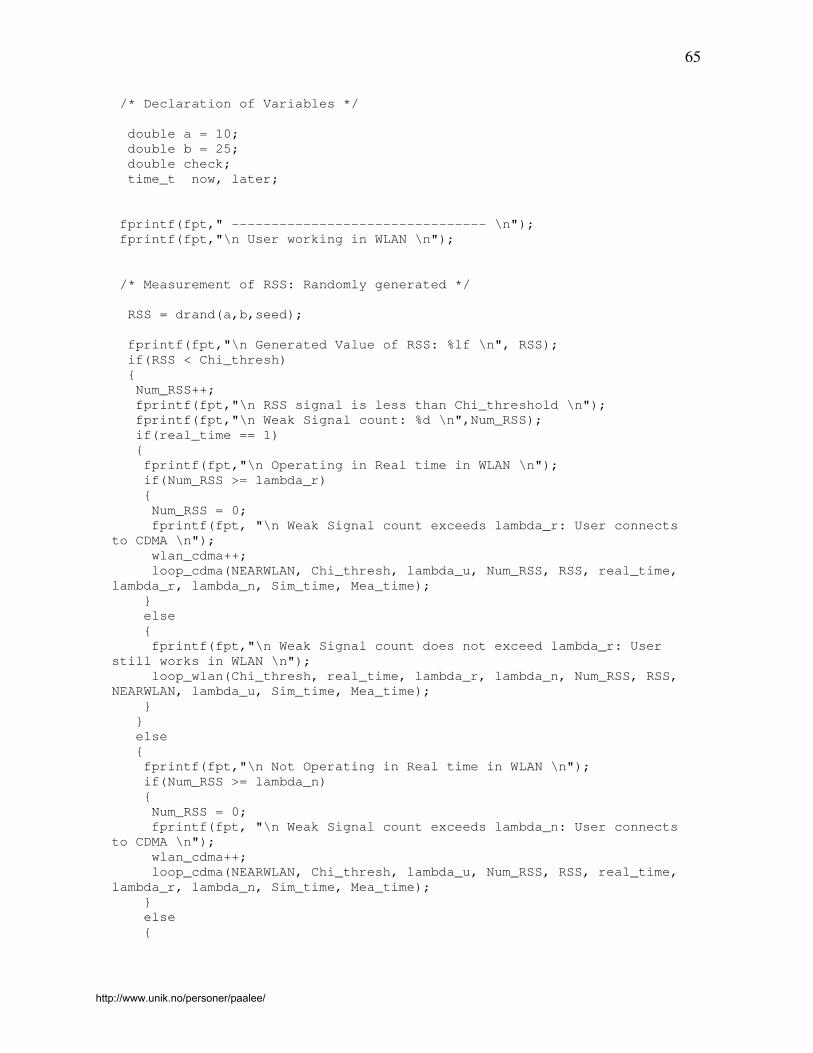
65
/* Declaration of Variables */
double a = 10;
double b = 25;
double check;
time_t now, later;
fprintf(fpt," -------------------------------- \n");
fprintf(fpt,"\n User working in WLAN \n");
/* Measurement of RSS: Randomly generated */
RSS = drand(a,b,seed);
fprintf(fpt,"\n Generated Value of RSS: %lf \n", RSS);
if(RSS < Chi_thresh)
{
Num_RSS++;
fprintf(fpt,"\n RSS signal is less than Chi_threshold \n");
fprintf(fpt,"\n Weak Signal count: %d \n",Num_RSS);
if(real_time == 1)
{
fprintf(fpt,"\n Operating in Real time in WLAN \n");
if(Num_RSS >= lambda_r)
{
Num_RSS = 0;
fprintf(fpt, "\n Weak Signal count exceeds lambda_r: User connects
to CDMA \n");
wlan_cdma++;
loop_cdma(NEARWLAN, Chi_thresh, lambda_u, Num_RSS, RSS, real_time,
lambda_r, lambda_n, Sim_time, Mea_time);
}
else
{
fprintf(fpt,"\n Weak Signal count does not exceed lambda_r: User
still works in WLAN \n");
loop_wlan(Chi_thresh, real_time, lambda_r, lambda_n, Num_RSS, RSS,
NEARWLAN, lambda_u, Sim_time, Mea_time);
}
}
else
{
fprintf(fpt,"\n Not Operating in Real time in WLAN \n");
if(Num_RSS >= lambda_n)
{
Num_RSS = 0;
fprintf(fpt, "\n Weak Signal count exceeds lambda_n: User connects
to CDMA \n");
wlan_cdma++;
loop_cdma(NEARWLAN, Chi_thresh, lambda_u, Num_RSS, RSS, real_time,
lambda_r, lambda_n, Sim_time, Mea_time);
}
else
{
http://www.unik.no/personer/paalee/

66
fprintf(fpt,"\n Weak Signal count does not exceed lambda_n: User still
works in WLAN \n");
loop_wlan(Chi_thresh, real_time, lambda_r, lambda_n, Num_RSS, RSS,
NEARWLAN, lambda_u, Sim_time, Mea_time);
}
}
}
else
{
Num_RSS = 0;
fprintf(fpt,"\n Signal strong so Count reset: User Continues to work
in WLAN \n");
loop_wlan(Chi_thresh, real_time, lambda_r, lambda_n, Num_RSS, RSS,
NEARWLAN, lambda_u, Sim_time, Mea_time);
}
}
/* End of WLAN function */
/* Start of CDMA function of the algorithm */
int loop_cdma(int NEARWLAN, double Chi_thresh, int lambda_u, int
Num_RSS, double RSS, int real_time, int lambda_r, int
lambda_n, int Sim_time, int Mea_time)
{
/* Gets end time of Simulation */
time(&end);
count_cdma++;
scale_time++;
/* Carries the Simulation for Sim_time seconds */
if( (scale_time) >= scale_measure)
return 0;
/* Declaration of Variables */
double a = 10;
double b = 25;
double check;
time_t now, later;
fprintf(fpt," -------------------------------- \n");
fprintf(fpt,"\n User working in CDMA \n");
/* Generate NEARWLAN randomly */
NEARWLAN = irand(0,1,seed);
if(NEARWLAN == 1)
{
fprintf(fpt,"\n User working in region near WLAN \n");
/* Measurement of RSS: Randomly generated */
http://www.unik.no/personer/paalee/

67
RSS = drand(a,b,seed);
fprintf(fpt,"\n Generated Value of RSS: %lf \n", RSS);
if(RSS > Chi_thresh)
{
Num_RSS++;
fprintf(fpt,"\n RSS signal is greater than Chi_threshold \n");
fprintf(fpt,"\n Strong Signal count: %d \n",Num_RSS);
if(Num_RSS >= lambda_u)
{
Num_RSS = 0;
fprintf(fpt, "\n Strong Signal count exceeds lambda_u: User connects
to WLAN \n");
wlan_cdma++;
loop_wlan(Chi_thresh, real_time, lambda_r, lambda_n, Num_RSS, RSS,
NEARWLAN, lambda_u, Sim_time, Mea_time);
}
else
{
fprintf(fpt, "\n Strong Signal count does not exceed lambda_u: User
still works in CDMA \n");
loop_cdma1(NEARWLAN, Chi_thresh, lambda_u, Num_RSS, RSS, real_time,
lambda_r, lambda_n, Sim_time, Mea_time);
}
}
else
{
Num_RSS = 0;
fprintf(fpt, "\n Signal Weak Strong signal count reset: User still
works in CDMA \n");
loop_cdma(NEARWLAN, Chi_thresh, lambda_u, Num_RSS, RSS, real_time,
lambda_r, lambda_n, Sim_time, Mea_time);
}
}
else
{
fprintf(fpt,"\n User is not working in region near WLAN \n");
loop_cdma(NEARWLAN, Chi_thresh, lambda_u, Num_RSS, RSS, real_time,
lambda_r, lambda_n, Sim_time, Mea_time);
}
}
/* End of CDMA function */
/* Start of CDMA1 function of the algorithm */
int loop_cdma1(int NEARWLAN, double Chi_thresh, int lambda_u, int
Num_RSS, double RSS, int real_time, int lambda_r, int
lambda_n, int Sim_time, int Mea_time)
{
/* Gets end time of Simulation */
http://www.unik.no/personer/paalee/

68
time(&end);
count_cdma++;
scale_time++;
/* Carries the Simulation for Sim_time seconds */
if( (scale_time) >= scale_measure)
return 0;
/* Declaration of Variables */
double a = 10;
double b = 25;
double check;
time_t now, later;
fprintf(fpt," -------------------------------- \n");
fprintf(fpt,"\n User working in CDMA \n");
/* Measurement of RSS: Randomly generated */
RSS = drand(a,b,seed);
fprintf(fpt,"\n Generated Value of RSS: %lf \n", RSS);
if(RSS > Chi_thresh)
{
Num_RSS++;
fprintf(fpt,"\n RSS signal is greater than Chi_threshold \n");
fprintf(fpt,"\n Strong Signal count: %d \n",Num_RSS);
if(Num_RSS >= lambda_u)
{
Num_RSS = 0;
fprintf(fpt, "\n Strong Signal count exceeds lambda_u: User connects
to WLAN \n");
wlan_cdma++;
loop_wlan(Chi_thresh, real_time, lambda_r, lambda_n, Num_RSS, RSS,
NEARWLAN, lambda_u, Sim_time, Mea_time);
}
else
{
fprintf(fpt, "\n Strong Signal count does not exceed lambda_u: User
still works in CDMA \n");
loop_cdma1(NEARWLAN, Chi_thresh, lambda_u, Num_RSS, RSS, real_time,
lambda_r, lambda_n, Sim_time, Mea_time);
}
}
else
{
Num_RSS = 0;
fprintf(fpt, "\n Signal Weak Strong signal count reset: User still
works in CDMA \n");
loop_cdma(NEARWLAN, Chi_thresh, lambda_u, Num_RSS, RSS, real_time,
lambda_r, lambda_n, Sim_time, Mea_time);
}
}
/* End of CDMA1 function */
http://www.unik.no/personer/paalee/

69
Appendix – B
Input file for the C code:
Working in WLAN (1 for yes : 0 for no) : 1
Near WLAN if working in CDMA : 0
Value of Chi_thresh : 30
Service Class realtime: 1 else 0 : 1
Value of λr : 1 Value of λn : 1 Value of lambda_u : 20
Total Simulation Time in Seconds : 60
Signal Measuring Interval in Seconds : 10
http://www.unik.no/personer/paalee/

70
Appendix – C
Sample results of the simulation:
Sample Result 1: INPUT VALUES OF THE SIMULATION
--------------------------------
Working in WLAN : 1 for yes : 0 for no : 1
Near WLAN if working in CDMA : 0
Value of Chi_thresh : 30.000000
Service Class realtime if 1 else 0 : 1
Value of λ : 2
Value of λn : 1
Value of lambda_u : 20
Total Simulation Time in Seconds : 100
Signal Measuring Interval in Seconds : 10
--------------------------------
--------------------------------
Working in WLAN at the start of Simulation
--------------------------------
--------------------------------
User working in WLAN
Generated Value of RSS: 18.423441
RSS signal is less than Chi_threshold
Weak Signal count: 1
Operating in Real time in WLAN
Weak Signal count does not exceed λr: User still works in WLAN
--------------------------------
User working in WLAN
Generated Value of RSS: 12.773286
RSS signal is less than Chi_threshold
Weak Signal count: 2
http://www.unik.no/personer/paalee/

71
Operating in Real time in WLAN
Weak Signal count exceeds λr: User connects to CDMA
--------------------------------
User working in CDMA
User is not working in region near WLAN
--------------------------------
User working in CDMA
User working in region near WLAN
Generated Value of RSS: 14.892403
Signal Weak Strong signal count reset: User still works in CDMA
--------------------------------
User working in CDMA
User working in region near WLAN
Generated Value of RSS: 23.400587
Signal Weak Strong signal count reset: User still works in CDMA
--------------------------------
User working in CDMA
User working in region near WLAN
Generated Value of RSS: 12.274121
Signal Weak Strong signal count reset: User still works in CDMA
--------------------------------
User working in CDMA
User is not working in region near WLAN
--------------------------------
User working in CDMA
User is not working in region near WLAN
--------------------------------
User working in CDMA
http://www.unik.no/personer/paalee/

72
User is not working in region near WLAN
--------------------------------
SIMULATION STATISTICS
--------------------------------
Time spent in WLAN network : 20 seconds
Time spent in CDMA network : 80 seconds
Changes between WLAN and CDMA : 1
--------------------------------
--------------------------------
Simulation Ended Successfully
--------------------------------
Sample Result 2:
INPUT VALUES OF THE SIMULATION
--------------------------------
Working in WLAN : 1 for yes : 0 for no : 0
Near WLAN if working in CDMA : 1
Value of Chi_thresh : 20.000000
Service Class realtime if 1 else 0 : 1
Value of λr : 1
Value of λn : 2
Value of lambda_u : 2
Total Simulation Time in Seconds : 100
Signal Measuring Interval in Seconds : 10
--------------------------------
--------------------------------
Working in CDMA at the start of Simulation
User located near WLAN
--------------------------------
--------------------------------
User working in CDMA
User working in region near WLAN
Generated Value of RSS: 12.773286
http://www.unik.no/personer/paalee/

73
Signal Weak Strong signal count reset: User still works in CDMA
--------------------------------
User working in CDMA
User is not working in region near WLAN
--------------------------------
User working in CDMA
User working in region near WLAN
Generated Value of RSS: 14.892403
Signal Weak Strong signal count reset: User still works in CDMA
--------------------------------
User working in CDMA
User working in region near WLAN
Generated Value of RSS: 23.400587
RSS signal is greater than Chi_threshold
Strong Signal count: 1
Strong Signal count does not exceed lambda_u: User still works in CDMA
--------------------------------
User working in CDMA
Generated Value of RSS: 23.659622
RSS signal is greater than Chi_threshold
Strong Signal count: 2
Strong Signal count exceeds lambda_u: User connects to WLAN
--------------------------------
User working in WLAN
Generated Value of RSS: 12.274121
RSS signal is less than Chi_threshold
http://www.unik.no/personer/paalee/

74
Weak Signal count: 1
Operating in Real time in WLAN
Weak Signal count exceeds λr: User connects to CDMA
--------------------------------
User working in CDMA
User is not working in region near WLAN
--------------------------------
User working in CDMA
User is not working in region near WLAN
--------------------------------
User working in CDMA
User is not working in region near WLAN
--------------------------------
SIMULATION STATISTICS
--------------------------------
Time spent in WLAN network : 10 seconds
Time spent in CDMA network : 90 seconds
Changes between WLAN and CDMA : 2
--------------------------------
----------------------
Simulation Ended Successfully
--------------------------------
http://www.unik.no/personer/paalee/