Embed Size (px)
Citation preview
Bradley Natarian
Advisor: Prof. Rick Blum
Implementation of Passive Radar with a
Software Defined Radio Platform
Acknowledgement(s):
Jacob A. Gilbert and Jack L. Burbank – Johns Hopkins Applied Physics Laboratory
John W. Franklin – University of North Texas
Mark A. Richards – Georgia Tech
David and Lorraine Freed Undergraduate Research Symposium, Lehigh University
Electrical and Computer Engineering
Lehigh University, Bethlehem, PA
Passive radar:
• Uses the reflected energy of electromagnetic
waves from third-party sources (illuminators of
opportunity) to detect and track targets
• Does not require a transmitter
• Advantages compared to traditional radar systems
• Cost effective
• Can be used for covert operations
• Difficult to jam
Definitions
Software Defined Radio (SDR):
A radio system comprised of:
• Wideband, software independent
hardware
• Signal processing executed on a general
purpose processor
• Can be used to explore a wide band of
frequencies
Approach
A single SDR passive radar receiver will be
simulated and implemented to prove that it can
detect the time of flight from an illuminator to a
target to the receiver.
• Electromagnetic waves are transmitted from an illuminator of opportunity
• These transmissions are received via two paths
• A direct path from the illuminator to the direct path receiver with known distance, 𝐷• A reflected path from the illuminator to the target to the reflected path receiver with unknown
distance, 𝑅𝐼 + 𝑅𝑅• The transmitted signal can be recovered by subtracting the delay, 𝑡𝐷,from the received signal,
𝑆𝐷 𝑡 − 𝑡𝐷 , to obtain the transmitted signal, 𝑆𝐷(𝑡)• The time of flight of the reflected path, (𝑡𝐼 + 𝑡𝑅), can be calculated with a matched filter
• Time of flight can then be used to calculate the total distance from the illuminator to the target to
the receivers, 𝑅𝐼 + 𝑅𝑅
Principles of Operation
• Use three receivers to triangulate the
position of the target relative to the
illuminator and receivers
• Build a working prototype of the
concepts described in this work
using software (e.g. GNURadio,
MATLAB) and SDR hardware (e.g.
RTL-SDR, USRP)
Future Implementations
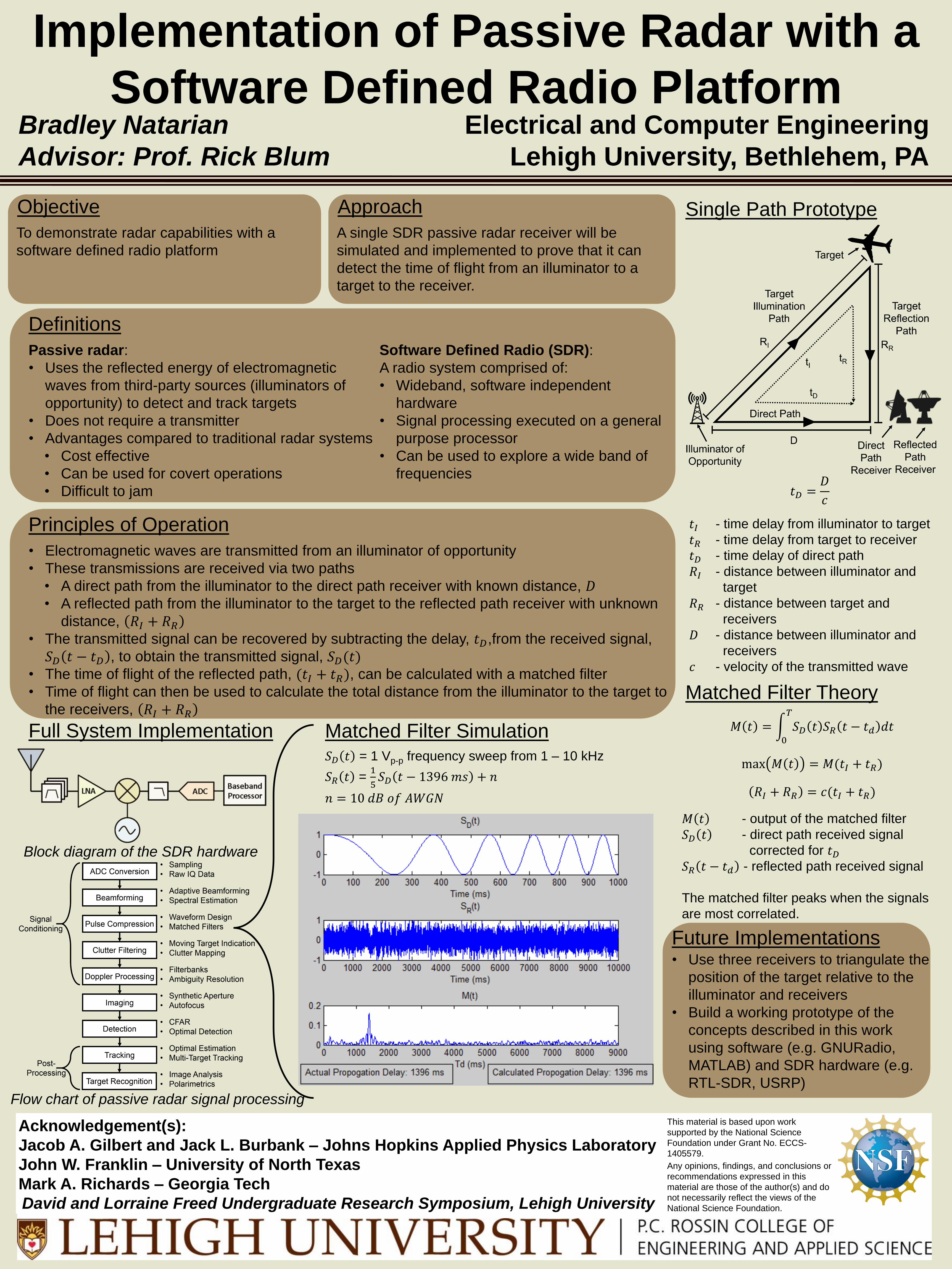
Block diagram of the SDR hardware
𝑡𝐷 =𝐷
𝑐
𝑡𝐼 - time delay from illuminator to target
𝑡𝑅 - time delay from target to receiver
𝑡𝐷 - time delay of direct path
𝑅𝐼 - distance between illuminator and
target
𝑅𝑅 - distance between target and
receivers
𝐷 - distance between illuminator and
receivers
𝑐 - velocity of the transmitted wave
Objective
To demonstrate radar capabilities with a
software defined radio platform
Flow chart of passive radar signal processing
Full System Implementation Matched Filter Simulation
Matched Filter Theory
Single Path Prototype
𝑀 𝑡 = 0
𝑇
𝑆𝐷 𝑡 𝑆𝑅 𝑡 − 𝑡𝑑 𝑑𝑡
max 𝑀 𝑡 = 𝑀(𝑡𝐼 + 𝑡𝑅)
𝑅𝐼 + 𝑅𝑅 = 𝑐(𝑡𝐼 + 𝑡𝑅)
𝑀 𝑡 - output of the matched filter
𝑆𝐷 𝑡 - direct path received signal
corrected for 𝑡𝐷𝑆𝑅 𝑡 − 𝑡𝑑 - reflected path received signal
The matched filter peaks when the signals
are most correlated.
𝑆𝐷 𝑡 = 1 Vp-p frequency sweep from 1 – 10 kHz
𝑆𝑅 𝑡 = 1
5𝑆𝐷 𝑡 − 1396 𝑚𝑠 + 𝑛
𝑛 = 10 𝑑𝐵 𝑜𝑓 𝐴𝑊𝐺𝑁
This material is based upon work
supported by the National Science
Foundation under Grant No. ECCS-
1405579.
Any opinions, findings, and conclusions or
recommendations expressed in this
material are those of the author(s) and do
not necessarily reflect the views of the
National Science Foundation.