Embed Size (px)
Citation preview

Bit-level Arithmetic ([email protected])
Implementation of DSP IC
Implementation of DSP IC
Lecture 9 Bit-Level Arithmetic Architecture
1

Bit-level Arithmetic ([email protected])
Fixed Point Representation• A W-bit fixed point 2’s complement number A is
represented as:A=aw-1◦aw-2…a1a0
where the bits ai, 0≤i≤W-1, are either 0 or 1, and the msb is the sign bit.
• The value of A is in the range of [-1,1-2-W+1] and is given byA=-aw-1+∑aw-1-i2-i
• For bit-serial implementations, constant word length multipliers are considered. For a WW bit multiplication, the W most-significant bits of the (2W-1)-bit product are retained. (the others are discarded)
2

Bit-level Arithmetic ([email protected])
Fixed Point MultiplicationLet the multiplicand and the multiplier be A and B:
The radix point is to the right of the msb p2W-2Full-precision
A constant word-length representation
3

Bit-level Arithmetic ([email protected])
Example: W=4• A = a3◦a2a1a0=-a3 + a22-1 + a12-2 + a02-3
• B = b3◦b2b1b0=-b3 + b22-1 + b12-2 + b02-3
• Multiplication of AB
4

Bit-level Arithmetic ([email protected])
AB with W=4
0123456
3
03132333
02122232
01112131
00102030
0123
0123
pppppppbabababab
abababababababab
ababababbbbbaaaa
b0A
b1A
b2A
- b3A
The additions cannot be carried out directly due to the terms with negative weight !!
Horner’s rule
5

Bit-level Arithmetic ([email protected])
Sign Extension & Shift
01233
30
21
1233
30
21
1230123
2222
222
aaaaaaaaaa
aaaaaaaaA
01233
40
31
22
133
130
21
1233
130
21
123
10123
1
2222
22222
222222
aaaaaaaaaa
aaaaa
aaaaaaaaA
1233 aaaa
The extension sign bit remains the msb position, while a0 is eliminated !!
6

Bit-level Arithmetic ([email protected])
AB with W=4Negative MSBs solved with sign extension, one in each partial product
Not used if the result is truncated
7

Bit-level Arithmetic ([email protected])
2’s Complement System• 2’s complement adder
ADDER
n n
n
X Y
Z
CinCout
0000016100000550101
1151011
zZwWyiyYxixX
x+y+cin=2ncout+z2’s complement
integer
8

Bit-level Arithmetic ([email protected])
To Speed Up Multiplication• To accelerate accumulation• To reduce the number of partial products
xxxxxxxxxxxxxxxxxxxxxxxxxxxxxx
11111100000000001
5 partial products may be required
To record into signed-bit representation with fewer number of nonzero bits
9

Bit-level Arithmetic ([email protected])
Booth’s Modified Algorithm• Recode binary numbers xi{0,1} to yi{-2,-1,0,1,2}
(5-level Booth recoding)• Five possible digits in yi radix-5 ?• Overlapping method is used to reach radix 4• Five digits require coding by 3 binary bits, that is
two binary and one overlapping bit is used.• The digits xi+1 and xi are recoded into signed digit
yi, with xi-1 serving as a reference bit.
yi = -2xi+1 + xi + xi-1
10

Bit-level Arithmetic ([email protected])
Example
-1 2’s complement conversion2 shift one step (or multiply by 2)-2 2’s complement conversion and shift
12

Bit-level Arithmetic ([email protected])
2-Operand Addition• 1-bit adder (full-adder module)
FA
xi yi
zi
CiCi+1
2
2mod
1iii
i
iiii
cyxc
cyxz
Adder schemes:• Switched carry-ripple adder• Carry-skip adder• Carry-lookahead adder• Prefix adder• Carry-select adder• Conditional-sum adder
• Carry-save adder• Signed-digit adder
13

Bit-level Arithmetic ([email protected])
Parallel Carry-Ripple Array (CRA) Multiplier
• The carry output of an adder is rippled to the adder input to the left in the same row.
• Bit-level dependence graph (DG) of 44-bit carry-ripple array multiplication:
Details please see Fig. 13.4
14

Bit-level Arithmetic ([email protected])
Interleaved Approach for FIR• Y(n)=x(n) + f x(n-1) + g x(n-2), f and g are
constants• To perform the computation and accumulation of
partial products associated with f and g simultaneously
• Since the truncation is applied at the final step, it leads to better accuracy.
• If the coefficients are interleaved in such a way that their partial products are computed in different rows, the resulting architecture is called bit-plane architecture
15

Bit-level Arithmetic ([email protected])
The switching time instances can be derived by scheduling the bit-level computations (Fig. 13.16)
17

Bit-level Arithmetic ([email protected]) 18

Bit-level Arithmetic ([email protected]) 20

Bit-level Arithmetic ([email protected]) 21

Bit-level Arithmetic ([email protected])
Bit-Serial FIR Filter• Constant coefficients are decomposed and
implemented using bit-serial shifts and adds.• Apply feedforward cutset retiming and replacing
the delayed scaling operators with switches, a feasible bit-serial pipelined bit-serial FIR filter can be derived.
22

Bit-level Arithmetic ([email protected])
ExampleA word-level delay is equivalent to W bit-level delaysWordlength=8
23

Bit-level Arithmetic ([email protected])
2-loops
Inner loop : 1DOuter loop: 2D
Inner : 6DOuter: 14D
Bit-serial implementation
2D26

Bit-level Arithmetic ([email protected])
Bit-Serial IIR• It is possible that the loops in the intermediate
bit-level pipelined architecture may contain more than WND number of bit-level delay elements the wordlength needs to be increased !!
• The wordlength is a parameter• The minimum feasible wordlength of a bit-level
pipelined bit-serial system decides its maximum throughput.
• The minimum feasible wordlength is constrained by the iteration bound of the SFG.
• Note: the minimum wordlength of the above example is 6
27

Bit-level Arithmetic ([email protected])
IIR Examples
TM+2TA TM+TA
4
1
Minimum feasible wordlength=6 Minimum feasible wordlength=5Throughput = 1 output/6 cycles Throughput = 1 output/5 cycles
(word)28

Bit-level Arithmetic ([email protected])
Canonic Signed Digit (CSD)• For fixed constant coefficient multiplications• Encoding a binary number such that it contains
the fewest number of non-zero bit• Example: A sequence of ones can be replaced with
– A “-1” at the least significant position of the sequence– A “1” at the position to the left of the most significant
position of the sequence– Zeros between the “1” and the “-1”
0 1 1 1 0 1 0 1 1 0 1 1 1 0 1 1 0 -10 1 1 1 1 0 -1 0 -11 0 0 0 -1 0 -1 0 -1
It can save more than 2/3 of the adder cells in an average !!
29

Bit-level Arithmetic ([email protected])
Properties of CSD Numbers
Please refer to the reference.
30
Bit-level Arithmetic ([email protected])
Remarks• Booth’s Modified Algorithm
– For variable coefficients
• Canonical Signed Digit– For fixed coefficients– Optimal
31

Bit-level Arithmetic ([email protected])
Horner’s Rule for Precision Improvement
• The truncation errors introduced in the constant wordlength multiplier not only depend on the multiplicand and multiplier value, but also on the arrangement of the partial product accumulation.
• Horner’s Rule: to delay the scaling operations common to the 2 partial products. That is, by applying partial products accumulation to reduce the truncation error.
• Example: x2-5 + x2-3 can be implemented as (x2-2+x)2-3 to increase the accuracy
32

Bit-level Arithmetic ([email protected])
Latency Reduction• With the same hardware complexity, the tree
type arrangement can reduce the latency from (N-1)TA to log2N TA
Linear arrangementBinary tree arrangement
34

Bit-level Arithmetic ([email protected])
Distributed Arithmetic• Usually used in summation of inner products• E.g.
ci are M-bit constants and xi are W-bit numbers
35

Bit-level Arithmetic ([email protected]) 36

Bit-level Arithmetic ([email protected])
CORDIC Algorithm• Iterative algorithm for circular rotations
– Example: sin, cos, to derive polar coordinates, …
• No multiplication
• CORDIC– COordinate Rotation DIigital Computer– Presented by Jack E. Volder 1959
37

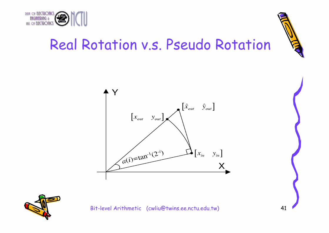
Bit-level Arithmetic ([email protected])
Rotation• Definition
(xin,yin)
(xout,yout)
4 multiplications and 2 additions !!
39

Bit-level Arithmetic ([email protected])
Basic Concept of CORDIC Operation
• To decompose the desired rotation angle into the weighted sum of a set of predefined elementary rotation angles (i), i=0,1,2, …, W
• Consequently, the rotation through each of them can be accomplished with simple shift-and-add operation
• No Multiplication at all !!
40

Bit-level Arithmetic ([email protected])
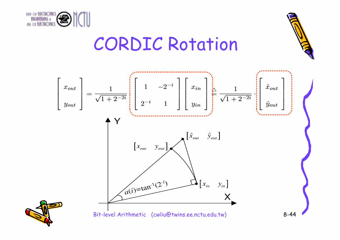
Conventional CORDIC Algorithm
)(
)(
)1(
)1(
.cossinsincos
i
i
i
i
yx
yx
)(
)(
)1(
)1(
1221
i
i
ii
ii
i
i
yx
yx
)(
)(
)1(
)1(
1tantan1
cos i
i
i
i
yx
yx
iii
ii 2tan2tan 11
where
45

Bit-level Arithmetic ([email protected])
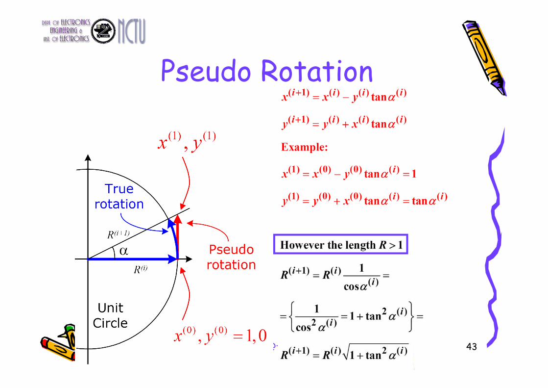
Pseudo Rotation Example• The angle is known. • Derive x,y using three
iterations• The vector length R is
increasing during each iterations
14 ,6.26 ,45 321
46

Bit-level Arithmetic ([email protected]) 50

Bit-level Arithmetic ([email protected]) 53

Bit-level Arithmetic ([email protected])
CORDIC Summary• +++:
– Simple shift-and-add operation – Small area
• ---:– It needs n iterations to obtain n-bit
precision – Slow carry-propagate addition– Area consuming shifts (Barrel Shifter)
54

Bit-level Arithmetic ([email protected])
Summary of CORDIC Algorithm Both micro-rotation and scaling phases
Ref: Y. H. Hu, “CORDIC-based VLSI architecture for digital signal processing,” IEEE Signal Processing Mag., pp. 16-35, July 1992. 55

Bit-level Arithmetic ([email protected])
Modes of CORDIC Operations
0)(
)(iz(N)-z(N)-z(0)1
0
Nz
imN
i
a
θRotational Sequence
= sign of z(i)
• Vector rotation mode (θ is given)– The objective is to compute the final vector
• Usually , we set z(0)= θ
after the N-th iteration
Tff yx ,
Tff yx ,
i
56

Bit-level Arithmetic ([email protected])
Scaling Operation• Scaling operation is used to maintain
the “norm” of the original vector
57

Bit-level Arithmetic ([email protected])
Enhancement of CORDIC• Architecture
– Pipelined architecture– Faster adder
• Algorithm– Radix-4 CORDIC– MVR-CORDIC– EEAS-CORDIC
58

Bit-level Arithmetic ([email protected])
Pipelined architecture• Expand folded CORDIC processor to
achieve the pipelined architecture• Shifting can be realized by wiring
59

Bit-level Arithmetic ([email protected])
Faster Adder (CSA)
+
+
+
sign
Ripple Adder and its sign calculation
carry
sum +
+
+
+
+
+
CSA VMAand its sign calculation
carry
sum sign
60

Bit-level Arithmetic ([email protected])
Critical Path of CSA In on-line approach, we want to get sign bit as soon as possible !
Redundant Number System to be used to obtain the sign bit quickly
+
+
+
+
+
+
sign
CSA VMA
+
+
+
sign
CSA VMARNS
61

Bit-level Arithmetic ([email protected])
Radix-4 CORDIC• Reduce Iteration Numbers
– High radix CORDIC.(e.g. Radix-4, Radix-8)• 1 stage of Radix-4 = two stages of Radix-2
– Faster computation at higher cost• Employ the Radix-4 micro-rotations to
– Reduce the stage number.
62

Bit-level Arithmetic ([email protected])
Modified Vector Rotation (MVR)• Skip some micro-rotation angles
– For certain angles, we can only reduce the iteration number but also improve the error performance.
– For example, =/4
ConventionalCORDIC
1, 1, 1, 1, 1,
MVR-CORDIC 1, 0, 0, 0, 0,
m= 7.2*10-3
m= 0
63

Bit-level Arithmetic ([email protected])
MVR CORDIC Algorithm• Repeat some micro-rotation angles
– Each micro-rotation angle can be performed repeatedly– For example, =/2: execute the micro-rotation of a(0)
twice
• Confine the number of micro-rotations to Rm– In conventional CORDIC, number of iteration=W– In the MVR-CORDIC, Rm << W– Hardware/timing alignment
64

Bit-level Arithmetic ([email protected])
MVR CORDIC Algorithm• With above three modification
where s(i) {0, 1, 2, …, W} is the rotational sequence
that determines the micro-rotation angle in the ith iteration
(i) {-1, 0 ,1} is the directional sequence that controls the direction of the ith micro-rotation
65

Bit-level Arithmetic ([email protected])
Constellation of Reachable Angles
(a) Conventional CORDIC with N=W=4(b) MVR-CORDIC with W=4 and Rm=3
66
Bit-level Arithmetic ([email protected])
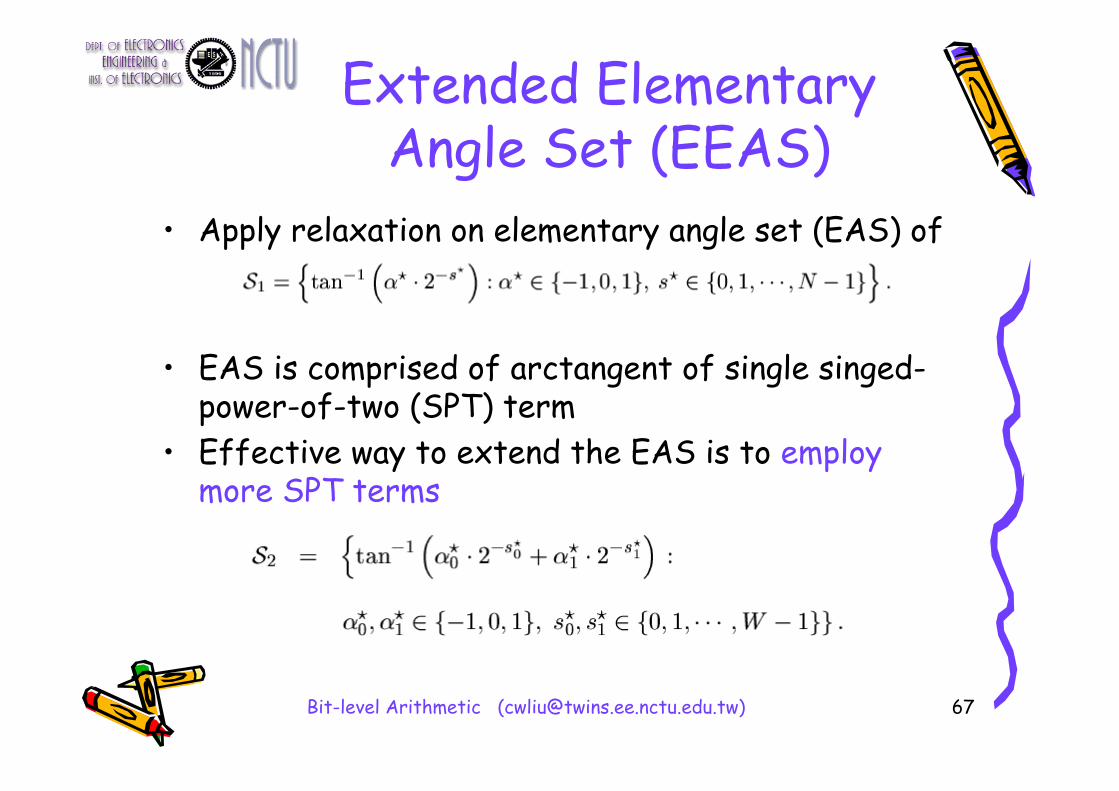
Extended Elementary Angle Set (EEAS)
• Apply relaxation on elementary angle set (EAS) of
• EAS is comprised of arctangent of single singed-power-of-two (SPT) term
• Effective way to extend the EAS is to employ more SPT terms
67

Bit-level Arithmetic ([email protected])
Example of EAS and EEAS
Example of elementary angles of (a) EAS S1, (b) EEAS S2, with wordlength W=3.
68

Bit-level Arithmetic ([email protected])
Constellation of EEAS
Constellation of elementary angles of (a) EAS S1, (b) EEAS S2, with wordlength W=8.
69

Bit-level Arithmetic ([email protected])
Angle Quantization• Approximation is applied on “ANGLE”• Decompose target angle into sub-angles
70
Bit-level Arithmetic ([email protected])
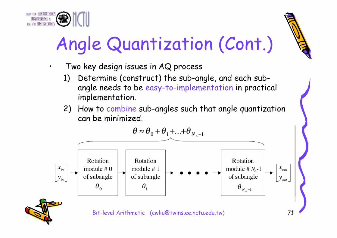
Angle Quantization (Cont.)• Two key design issues in AQ process
1) Determine (construct) the sub-angle, and each sub-angle needs to be easy-to-implementation in practical implementation.
2) How to combine sub-angles such that angle quantization can be minimized.
71

Bit-level Arithmetic ([email protected])
Angle Quantization (Cont.)• AQ process is conceptually similar to Sum-of-
Power-of-Two (SPT) quantization
72

Bit-level Arithmetic ([email protected])
Angle Quantization (Cont.)• Correspondences between AQ process and
SPT (CSD) quantization process
73

Bit-level Arithmetic ([email protected])
Conclusion• Rotational Engine plays an important role in
modern DSP systems• The conventional CORDIC is an interesting idea to
reduce VLSI hardware cost in implementing the rotation operation (as well as other arithmetic operations).
• The idea of Angle Quantization is firstly introduced in Ref. [4,5]. It is analogous to the SPT concept in quantizing floating-point numbers.
• Most CORDIC-related algorithms can be explained using the AQ design framework
74

Bit-level Arithmetic ([email protected])
Reference1. Y.H. Hu,, “CORDIC-based VLSI architectures for digital signal processing”, IEEE
Signal Processing Magazine , Vol. 9, Issue: 3, pp. 16 -35, July 1992.2. E. Antelo, J. Villalba, J.D. Bruguera, and E.L. Zapata,” High performance rotation
architectures based on the radix-4 CORDIC algorithm”, IEEE Transactions on Computers, Vol. 46, Issue: 8, Aug. 1997.
3. C.S Wu and A.Y. Wu, “Modified vector rotational CORDIC (MVR-CORDIC) algorithm and architecture”, IEEE Trans. Circuits and systems-II: analog and digital signal processing, vol. 48, No. 6, June 2001.
4. A.Y. Wu and C.S. Wu, “A unified design framework for vector rotational CORDIC family based on angle quantization process”, In Proc. of 2001 IEEE International Conference on Acoustics, Speech, and Signal Processing, Vol. 2, pp. 1233 -1236.
5. A. Y. Wu and Cheng-Shing Wu, “A Unified View for Vector Rotational CORDIC Algorithms and Architectures based on Angle Quantization Approach,” in IEEE Trans. Circuits and Systems Part-I: Fundamental Theory and Applications, vol. 49, no. 10, pp. 1442-1456, Oct. 2002.
6. C. S. Wu and A. Y. Wu, “A novel trellis-based searching scheme for EEAS-based CORDIC algorithm” In Proc. of 2001 IEEE International Conference on Acoustics, Speech, and Signal Processing, Vol. 2 , pp. 1229 -1232.
75


![Chapter 1 Introduction - National Chiao Tung University · The Multiplier-Accumulator (MAC) unit is the major component of DSP processors, and it consumes nearly one half powers [2.10]](https://img.pdfslide.us/doc/110x75/5e7ae0a6fdd9f44a25618e86/chapter-1-introduction-national-chiao-tung-university-the-multiplier-accumulator.jpg)