Embed Size (px)
Citation preview
Draft
Implementation of an In-Vessel Calibration Light Source for JETa)
T.M. Biewer,1,b) C. Belcher,2 I. Hassall,2 D.L. Hillis,1 G. Kaveney,3 D. Scharpf,4 M.F. Stamp,3 C. Stunell,3 K.-D. Zastrow,3 and JET EFDA contributorsc)
JET-EFDA, Culham Science Centre, Abingdon, OX14 3DB, UK 1Oak Ridge National Laboratory, Oak Ridge, Tennessee 37831, USA 2Oxford Technologies Ltd., Abingdon, OX14 1RG, UK 3EURATOM/CCFE Fusion Assoc., Culham Science Centre, Abingdon, OX14 3DB, UK 4Labsphere Inc., North Sutton, New Hampshire 03260, USA (Presented XXXXX; received XXXXX; accepted XXXXX; published online XXXXX) (Dates appearing here are provided by the Editorial Office) An in-vessel calibration light source (ICLS) has been implemented for remote use during extended shutdown periods of the Joint European Torus (JET). The ICLS facilitated the in-situ calibration of optical diagnostics, which previously were performed when the diagnostics were removed from JET. Since the ICLS is used to calibrate diagnostics over the entire, exact optical path as used when plasma discharge data is measured, the ICLS calibration implicitly accounts for any vignetting losses in the JET vessel viewports in addition to the vacuum window transmission. At least 10 diagnostic systems have benefited from the ICLS during the extended ITER-like wall shutdown of 2009-2011. Examples of the use of the ICLS in JET are given.
I. INTRODUCTION
The absolute intensity calibration of visible light diagnostics is an integral link in the scientific chain that connects ADC counts on a detector to plasma physics parameters. These calibrations are routinely accomplished on high temperature plasma devices through the use of integrating spheres coupled to a stable, broad spectrum, “white” light source of known radiance. These spheres are typically manually inserted (in-vessel) into the optical line-of-sight of a diagnostic during vacuum openings, e.g. on machines like ASDEX or NSTX. Such an operation is problematic for JET (and ITER and DEMO) due to in-vessel environmental hazards, e.g. radiation and contamination. An in-vessel calibration light source (ICLS) has been implemented for remote use during extended shutdown periods of JET.1 The ICLS is a 12 inch integrating sphere (4 inch opening) with 4 lamps, which can be positioned inside the JET vacuum vessel via the Remote-Handling Arm (RHA)2. The ICLS facilitated the in-situ calibration of optical diagnostics, which previously were performed when the diagnostics were removed from JET. Use of the ICLS has reduced the mechanical stresses associated with the repositioning of diagnostics for calibration purposes. Since the ICLS is used to calibrate diagnostics over the entire, exact optical path as used when plasma discharge data is measured, the ICLS calibration implicitly accounts for any vignetting losses in the JET vessel viewports in addition to the vacuum window transmission. The window transmission is included in the ICLS calibration across all visible wavelengths relevant to each diagnostic, and can be compared to off-line, 2-color laser transmission measurements using a retroreflector. The ICLS for JET is a demonstration technology for how such calibrations could be accomplished remotely on ITER. At least 10 diagnostic systems have benefited from the ICLS during the extended ITER-like wall shutdown of 2009-2011.
II. ICLS DEVICE DESCRIPTION The In-vessel Calibration Light Source is based on a 12 inch
diameter integrating sphere, commercially available from Labsphere, Inc.3 This diameter sphere was chosen since it is the maximum size sphere that could comfortably fit through the available vessel ports on JET, which are opened during machine access periods. It is typical for Labsphere to work with customers to customize their products for the intended applications. Some of the specifications of the ICLS are “standard,” while others are not.
Standard features for integrating spheres include the light-port opening diameter, the lamp type and configuration, and the high reflectance coating material. To ensure uniform radiance across the light exit-port, the sphere opening was limited to 4 inches in diameter. This opening was maximized to allow for easier accommodation of multiple lines of sight when calibrating. Four calibrated tungsten-halogen lamps were installed in two sizes: 5 W and 100W. This allowed for a wide range of radiance values (~ 1 to 2x40 mW/cm2-sr-µm at 600 nm) to accommodate diagnostics of varying sensitivity. An inner ceramic shell of Spectralon provides a robust, non-flaking (as opposed to Spectraflect paint), high reflectance, Lambertian light source. A radiometer was installed to give a measurement of the performance of the calibrated lamps over time, since the total illumination (and color temperature) can change from use. The radiometer also is useful for adjusting the calibration standard, which can vary slightly (hot bulb filaments sag, effecting the total radiance, but not the color temperature) as the orientation of the lamps relative to gravity is changed for various calibration positions.
Some atypical modifications were required for the ICLS due to unique aspects of the JET environment and the Remote Handling requirements. The outer Aluminum shell of the sphere is usually painted. However, to avoid the occurrence of a paint chip in the event of impact, the ICLS outer shell was anodized (prevents an oxide layer from forming), along with other system components. A high-luminance (~80 cd; ~4 mW/cm2-sr-µm at a)Contributed paper published as part of the Proceedings of the 19th Topical
Conference on High-Temperature Plasma Diagnostics, Monterey, California, May, 2012. b)[email protected]. c)See the appendix of F. Romanelli, et al., Proceedings of the 23rd IAEA Fusion Energy Conference 2010, Daejeon, Korea
Draft
600 nm), “white” LED was also installed, which could be used for non-calibrated illumination (of inside JET) from the ICLS, while the ICLS is being moved. This proved useful when rough-aligning some diagnostics. Since the calibrated tungsten-halogen bulb filaments are soft when hot (during illumination and for ~10 minutes thereafter), the ICLS should not be moved at all until the bulbs are cool, at the risk of invalidating the calibration standard of the bulb and/or destroying the filament entirely.
Electrical connections (power and data) are made to the
ICLS via a 20 m long, Remote Handling compatible “umbilical cable.” This distance is required for the ICLS to be able to reach essentially any JET in-vessel port. To maintain stable voltages and currents to the calibration lamps over this distance, non-standard (for Labsphere) power supplies were required. The umbilical consists of 3 multi-conductor cables (“No Smoke, Zero Halogen (NSZH)” jacketed to avoid contaminating JET in the event of an electrical fire or short circuit) of differing gauge wires (12 and 22 AWG), bundled together within a NSZH, abrasion resistant sleeve. The umbilical cable weighs ~2lb/m, and is much heaver itself than the ~20 lb ICLS head. In total, there are 28 =4+10+14 connections between the ICLS head and a half-rack of
electronics, which sits outside the JET vessel at the midplane. The electronics rack is connected to the internal JET network available in the torus hall, allowing the control computer to be located at essentially any distance (within the JET network), e.g. in the RH control room. The ICLS connectors are specially designed, multi-pin LEMO4 connectors that have had the locking mechanism removed, to be compatible with the JET Remote Handling MASCOT2 gripping mechanisms. A guide pin aids in locating the male (umbilical) and female (ICLS head) halves of the connector.
All connections to the ICLS head are made after the ICLS is brought in-vessel on a specially designed “transport cradle.” The cradle is carried by the “tool tray”, which is an ancillary RH boom for delivering items from ex-vessel to in-vessel. MASCOT grasps the cradle from the tool tray and sets the ICLS and cradle onto the “manned entry floor”, which has previously been installed in JET. The ME floor covers and protects the JET divertor assembly during in-vessel operations. The umbilical has also preemptively been fed through a midplane port, and stretched along the floor. MASCOT connects the umbilical to the ICLS head while it is sitting in the cradle. The cradle also serves as a place for the ICLS to be “parked” in-vessel, while the RH arm is required to perform other tasks. Once the umbilical and ICLS head are connected, a series of system tests are performed to demonstrate functionality. The umbilical cable is then attached to the ICLS head at a “tie point” to provide strain relief to the connectors themselves. As a final safety precaution prior to MASCOT manipulation of the ICLS, a winch-cable is connected between MASCOT and the ICLS. The ICLS is light enough that MASCOT can lift it “with one hand.” However, if both MASCOT grippers lose power and release the ICLS, the winch cable limits the distance that the ICLS falls.
An integral part of the ICLS is the light-exit port shuttering mechanism. The shutter, when closed, protects the ICLS from undue dust accumulation and unforeseen damage during transport. In the event of a catastrophic failure (e.g. due to a crushing impact), the shutter could also contain the shattered fragments of the Spectralon ceramic inside the ICLS. During normal operation, however, the shutter serves as a “screen,” on which back-lit diagnostic lines of sight are projected. The shutter blade has a rough (diffusing) finish and is landmarked with concentric circles, separated by 1 inch. This “bulls-eye target” is observed via a compact, low-lux CMOS camera (0.0003 lux, 600 TV lines, autoexposure), which is mounted on the shutter housing. The ICLS head is positioned while the camera image is observed, until the desired arrangement of back-lit fiber “spots” is attained. At that time, the servo mechanisms of the MASCOT and RH Arm joints are locked, and their positions recorded for future use. The shutter blade can then be retracted, allowing the diagnostic lines of sight to enter the ICLS. The diagnostic is then configured for data acquisition while the appropriate calibrated lamp is allowed to thermally stabilize (~15 minutes). During this time diagnostic settings (e.g. exposure) can be checked and optimized. Absolute irradiance calibrations from a uniform standard light source are then accomplished in the usual fashion. When complete, the calibrated lamp is turned off and allowed to cool (before moving the ICLS).
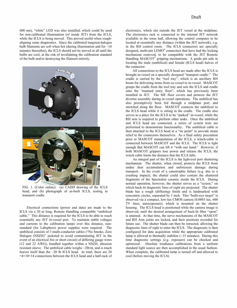
FIG. 1. (Color online): (a) CADD drawing of the ICLS head, and (b) photograph of as-built ICLS, resting in transport cradle.
Draft
Additionally, the ICLS is equipped with a “forward facing” camera, which is also mounted to the shutter housing, but has a view that is directed towards the back-lit diagnostic lines of sight, i.e. perpendicular to the plane of the shutter blade. This camera is otherwise identical to the shutter-viewing camera, and has the same wide-angle (70 degree horizontal) field of view. This camera has proven useful, along with the LED spot-light, for determining proximity to material structures inside JET, as well as looking toward in-vessel ports to identify back-lit periscopes and other distinctive objects. Moreover, in the event that the shutter-viewing camera experiences a failure, the forward-facing camera can be re-oriented ex-vessel by a technician to serve as a quick replacement.
Hastily added to the ICLS prior to initial implementation is a
passive structure, which provides simple, mechanical protection. The “bumper” is an annulus of Aluminum that is stood-off by posts from the rib that joins the two halves of the sphere. The opening in the bumper is wide enough that the bumper does not obstruct the forward-facing camera view or lines of sight entering the sphere (as confirmed by the shutter-viewing camera images). The bumper is however crucial for protecting the calibration lamps, cameras, shutter, radiometer, LED, and wiring from potential impacts and snags on structures in JET when the ICLS is in close proximity to them. The bumper also provides a flat surface that the ICLS can be safely sat down on the floor on, away from the transport cradle, e.g. in an emergency. The need for the bumper was not recognized until the ICLS was assembled on-site at JET. The bumper was not anodized, due to a pressing time constraint to begin calibration work.
III. CALIBRATION RESULTS
The ICLS was first utilized in JET during the ITER-like Wall intervention of 2009-2011. During this period the (erstwhile carbon fiber composite (CFC)) plasma facing material structure (e.g. ~8000 tiles) lining JET were replaced with a configuration that mimics the expected configuration of ITER: Beryllium tiles and structures in the main chamber and Tungsten and Tungsten-coated CFC’s in the divertor region. Because of the Be and T contamination of the JET in-vessel environment, the RH Arm and MASCOT were heavily tasked to accomplish this
replacement. Nevertheless, as the tile-replacement schedule allowed, the ICLS was deployed in-vessel, and diagnostic calibrations were accomplished in 4 sessions from Sept. 2010 to Feb. 2011. It was often the case that tile replacement work occupied two 8-hour shifts during the day, and ICLS work occupied the 8-hour shift at night. This arrangement enabled efficient utilization of effort, since many calibrations required only a brief hour of positioning the ICLS by a RH crew, followed by multiple hours of in-place calibrations (e.g. scanning a spectrometer over many wavelength and configuration settings.) In fact, since many JET diagnostics are remote configurable (motorized wavelength, shutter, and grating drives) from the control room, it was possible to “script” a calibration of a given diagnostic, minimizing any down-time associated with the data acquisition system. In this manner, 11 diagnostics system were absolute intensity calibrated on JET, including: visible spectroscopy and imaging diagnostics, charge-exchange recombination spectroscopy diagnostics, Zeeman spectroscopy diagnostics, VUV spectroscopy diagnostics, infrared imaging diagnostics, divertor spectroscopy diagnostics, and the high-resolution Thomson scattering diagnostic (in the JET vernacular: KS3, KS4, KS5, KS7, KS8, KS9, KE11, KL1, KL7, KT1, KT3, KT7).5 In total these calibrations required ~200 hours of clock-time, during which ~90 hours of calibration lamp-time were consumed. Since the coordinates of the RH Arm and MASCOT joints are recorded for each of the calibration positions, future in-vessel calibrations (e.g. Sept. 2012) should be able to quickly re-establish the locations, saving many hours of clock time.
IV. SUMMARY
The ICLS has demonstrated its usefulness to ease and enable the calibration of multiple diagnostic systems on JET. These calibrations were accomplished via remote handling, i.e. without any specific manned entry to the JET vessel. The ICLS will be an integral part in diagnostic calibrations on JET in the future, and provide a pathway for how such calibrations could be performed (remotely) on future devices, such as ITER and DEMO.
V. ACKNOWLEDGEMENTS
The views and opinions expressed herein do not necessarily reflect those of the European Commission. This work was performed under the European Fusion Development Agreement, supported by the European Communities and by the U.S Dept. of Energy, and carried out within the Contract of Association between EURATOM and the US D.O.E., contract DE-AC05-00OR22725. Moreover, kind regards are due to the engineering staff at Labsphere Inc.
VI. REFERENCES 1T. M. Biewer, D. L. Hillis, M. F. Stamp, K.-D. Zastrow, Rev. Sci. Instrum. 79, 10F530 (2008). 2D. Locke, Technical Report No. CDS/J408, U.K.A.EA. Culham Science Centre, Abingdon, UK OX14 3DB, 2004. 3Labsphere Inc., Sutton, New Hampshire, http://www.labsphere.com. 4LEMO Inc., Worthing, West Sussex, UK, http://www.lemo.co.uk. 5See the JET Data Handbook for more information on individual systems: http://users.jet.efda.org/pages/data-dmsd/jetdatahandbook/web/php/ViewEntry.php?type=0&order=0&view=0
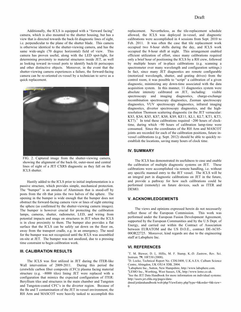
FIG. 2. Captured image from the shutter-viewing camera, showing the alignment of the back-lit, outer-most and central lines of sight of a JET CXRS diagnostic as they fall on the ICLS shutter.


![PRESSURE VESSEL [Proses Pembuatan Pressure Vessel]](https://img.pdfslide.us/doc/110x75/546b26fab4af9fc2128b4e24/pressure-vessel-proses-pembuatan-pressure-vessel.jpg)