Embed Size (px)
Citation preview

NASA / CR-1999-209327
Implementation of a Trailing-Edge Flap
Analysis Model in the NASA Langley
CAMRAD.MOD1/HIRES Program
Bruce Charles
•The Boeing Company, Mesa, Arizona
National Aeronautics and
Space Administration
Langley Research Center
Hampton, Virginia 23681-2199
Prepared for Langley Research Centerunder Contract NAS1-20096 Task 14
May 1999
https://ntrs.nasa.gov/search.jsp?R=19990047903 2020-04-25T21:53:53+00:00Z

Available from:
NASA Center for AeroSpace Information (CASI)7121 Standard Drive
Hanover, MD 21076-1320
(301) 621-0390
National Technical Information Service (NTIS)
5285 Port Royal Road
Springfield, VA 22161-2171(703) 605-6000
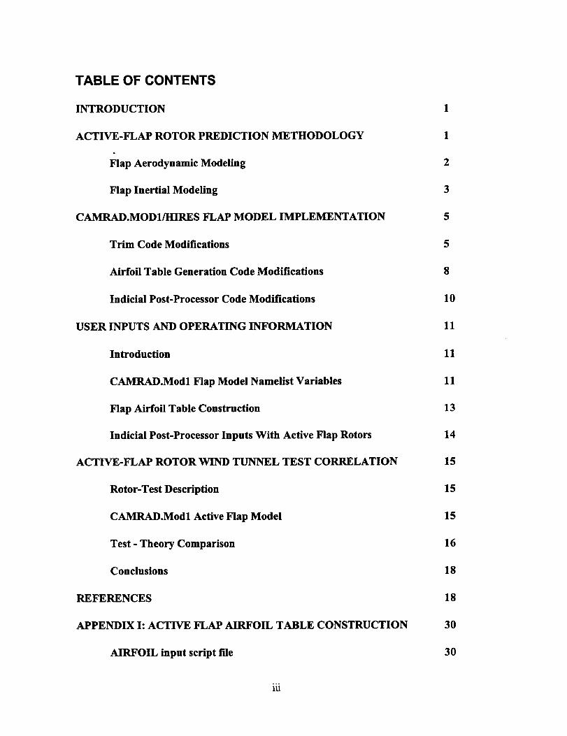
TABLE OF CONTENTS
INTRODUCTION
ACTIVE-FLAP ROTOR PREDICTION METHODOLOGY
Flap Aerodynamic Modeling
Flap Inertial Modeling
CAMRAD.MOD1/HIRES FLAP MODEL IMPLEMENTATION
Trim Code Modifications
Airfoil Table Generation Code Modifications
Indicial Post-Processor Code Modifications
USER INPUTS AND OPERATING INFORMATION
Introduction
CAMRAD.Modl Flap Model Namelist Variables
Flap Airfoil Table Construction
Indicial Post-Processor Inputs With Active Flap Rotors
ACTIVE-FLAP ROTOR WIND TUNNEL TEST CORRELATION
Rotor-Test Description
CAMRAD.Modl Active Flap Model
Test - Theory Comparison
Conclusions
REFERENCES
APPENDIX I: ACTIVE FLAP AIRFOIL TABLE CONSTRUCTION
AIRFOIL input script file
3
5
5
8
10
11
11
11
13
14
15
15
15
16
18
18
30
30

Sample C-81 table input: 0015ft0.c81
Sample AIRFOIL program output
APPENDIX II: CAMRAD.MOD1/HIRES INPUT/OUTPUT
CAMRAD.Modl input script file
CAMRAD.Modl output
lndicial Post-Processor input
30
32
35
35
37
75
iv

IntroductionContinual advances in rotorcraft performance, vibration and acoustic characteristics are being sought
by rotary-wing vehicle manufacturers to improve efficiency, handling qualities and community noiseacceptance of their products. The rotor system aerodynamic and dynamic behavior are among the keyfactors which must be addressed to meet the desired goals. Rotor aerodynamicists study how aidoadredistribution impacts performance and noise, and seek ways to achieve better airload distribution throughchanges in local aerodynamic response charactenstics. One method currently receiving attention is theuse of trailing-edge flaps mounted on the rotor blades to provide direct control of a portion of thespanwise lift characteristics. Flaps have been employed in the past by at least one manufacturer as ameans to trim the rotor in place of the more conventional blade root pitch control. However, when used inconjunction with root pitch control, the flap provides an additional degree of freedom available to modifythe liftdistribution above that necessary for rotor trim. As an independent control, it is possible to vary theflap angle in an arbitrary fashion using higher harmonic or non-harmonic inputs as functions of rotorazimuth position, and further, the inputs may differ between blades giving the capability of individual bladecontrol.
Thus a rotor with trailing-edge flaps exhibits several desirable features that may be used to exploredesigns for quieter and more efficient rotors. First, however, it is necessary to have the capability toperform detailed analysis of the new configurations which meet the stringent requirements needed foracoustics predictions. The following work describes the incorporation of a trailing-edge flap model in theCAMRAD.Modl/HIRES comprehensive rotororaft analysis code, Reference [1]. As described inReference [I], CAMRAD.Modl is an extensively updated version of the early public domain CAMRAD [2]code. The Modl code enables analysis of rotor behavior with the high temporal and spatial airloadresolution necessary for accurate acoustics calculations. Also, it contains a new wake model capable ofsimulatingsecondary trailing vortices which are expected to arise from the airload distributions producedby a flap located at the blade tip. The CAMRAD.Modl/HIRES analysis consists of three separateexecutable codes. These include the comprehensive trim analysis, CAMRAD.Modl, the Indicial Post-Processor, IPP, for high resolution airloads, and AIRFOIL, which produces the rotor airfoil tables from inputairfoil section characteristics. The modifications made to these components permitting analysis of flappedrotor configurations are documented herein along with user instructions detailing the new input variablesand operational notes. This information is intended to be used as a supplement to References [1] and [2].The current work also includes sample cases of the code predictions compared with wind tunnel testresults of the MDHS/NASA Active Flap Rotor tests conducted in the NASA Langley 14 x 22 foot SubsonicWind Tunnel [3].
Active-Flap Rotor Prediction MethodologyThe implementation of a trailing-edge flap in CAMRAD.MOD1 requires an aerodynamic model to definehow the local section characteristics will vary with the trailing-edge flap deflection angles in addition to theusual two dimensional angle-of-attack and Mach number variables. In the new model, the user may choosea method which employs flap coefficient increments that are added to the standard airfoil sectioncoefficients (without flaps) obtained from the usual data tables. Provisions have been made to computethe flap coefficient increments usingthin airfoil theory or by a curve fit of increments obtained usingKaman airfoil data [4]. A second option utilizes experimental or predicted airfoil characteristics for a flappedairfoil section which are read from C-81 data tables. In this method, the airfoil table format was expanded toinclude flap lift and hinge moment coefficient tables for use in estimating aidoads on the flap and the flapactuators. It should be noted that the CAMRAD.Modl flap model does not treat the flap motion as anadditional degree of freedom in the blade dynamics solution. The code would have to be substantiallyrewritten to achieve this capability. Thus, a simplified flap dynamic analysis was developed to permitestimation of the flap inertial contributions to the flap actuator loads.

The CAMRAD.Modl code modifications give the user two options for introducing trailing-edge flapmotion depending on the purpose of the flap. The First method employs the flap to trim the rotor and soits motion is controlled by the pilot's stick and possibly governor inputs. Here, the flap lift forces developpitching moments on the rotor blade about the feathering a_s to produce the blade collective and cyclicpitch changes needed for trim. In the second method the flap becomes an independent secondarycontrol while root pitch actuation remains as the primary trim control. In this case, the flap can be employedto control rotor twist as a function of flight condition or impose twist variations as a function of azimuth.Thus, the coding was written to permit flap motion inputs given in terms of higher harmonics or specifiedas arbitrarily functions of rotorazimuth. CAMRAD.Modl assumes the motion of all blades on the rotor areidentical, consequently individual blade control cannot be simulated.
Flap Aerodynamic ModelingA general treatment of the flap aerodynamics for rotors would consider its highly unsteady, three
dimensional and compressible flow environment. Most rotor codes utilize experimental airfoil data toinclude the effects of compressibility and correct the 2D data for unsteady effects and yawed flow.Unfortunately 2D airfoil tests for sections commonly employed on rotorcraft do not include configurationswith flaps. Thus an approximate means of adding flap effects to the available rotororaft airfoil data isdesired. Although the flap motion introduces unsteady effects in addition to the normal airfoil motions,these have been neglected and the usual Theodorson or indicialmethods are assumed valid for airfoilswith a trailing edge flap. Further, all correctionsapplied for yawed flow remain unaltered.
Aerodynamic Loads using Thin Airfoil Theory
Plain trailing-edge flaps with no gap effectively change the airfoil section camber. The resultingchanges in airfoil aerodynamic characteristics with deflected flaps can be analyzed using potential flowthin-airfoil theory. Thin-airfoil theory will give reasonably accurate prediction of the chordwise loading,section pitching moments and the angle of attack for zero lift. Prediction of the flap lift and flap hingemoments are less accurate in the absence of viscous effects which have significant influence near thesection trailing edge. However, experimental data is scarce for the relatively high Mach number conditionsin which the flaps will operate for most helicopter rotor applications. Thus, thin-airfoil theory can provide aneeded degree of approximation in the absence of test data.
The following thin-airfoil equations (see References [5,6]) have been utilized in CAMRAD.Modl toestimate the flap effects on the both the total section loadingand the flap loading.
c,= (reference chord = c)
Section moment, c/4 Cm = Cmo" m(5 (C_ =c)
Flaplift C. = C.o + noC,- n8 (Cr_ =cf)
Rap hingemoment Ch = Cho+ hoCl" h_ (C_ =C_)
where o_, C,o, C_and C,o are values at zero lift and zero flap deflection, a is the lift curve slope(perradian), ¢ isthe angle of attack (radian) and _ is the flap deflection angle (radian, positive TE down).Also,

k = (l/_){cos"(1-2E) + 2(E(1-E))1/2}
m= (a/_)(1-E)(E(1-E)) '12
no= (41aE){(_12) - cos "1 E112- (E(1-E)) 112}
n = --2.5556(1--E)
h0 = (-2/aE2){(3/2
h = (4/_ E2)(1-E)
Eqns (1-6)
-E)(E(1-E)) '12- (3/2 - 2E)[_/2 - cos" Ell2]}
(E(1-E))112{_/2 - cos "1 El/2 . (E(1-E) 112}
where E is the flap chord ratio (c f/ c). The influence of the flap on the section drag is accounted for using adrag coefficient increment of the following form:
C d = Cd(_.O) "l" AC d
ACd =al_ + a=8= + as(3s+ a4_4 (5 in degrees)
where the polynomial coefficients may be defined from Navier Stokes calculations or, perhaps, from someother means. Aerodynamic loads on the flap are obtained from the above coefficients as
Lf= 0.5rV2cfC,f
Mh=0.5rV 2 cf2ChSimilarly, the incremental section loads resultingfrom the flap deflection are defined to be
Ls= 0.5rV 2 ck<3
D s= 0.5rV 2 c(al_ + a2_52+ as_S+ a454)
Ms=-0.5rV 2 c2 mS
Flap Inertial Model
The following simplified inertial analysis of the flap has been included in the CAMRAD.Modl flapmodifications for the purpose of estimating control loading requirements. The blade section motionsconsidered are the out-of-plane flap bending (w) and precone, rotation about the feathering and elasticaxes (0b), and the trailing-edge flap deflection (3). In-plane motions and forces are neglected. Thefollowing quantities are used in the formulation:
I, flap inertia moment about hinge, slug-_m flap mass, slugr, R radial station, rotor radiusx. flap hinge offset from blade feather axis, Xh/R

x_ flap CG offset, positive aft of flap hinge, X_/Rw blade flapping motion
precone angleeb blade pitch angleet,, built-in twiste0 blade root pitch (includes control inputs, control system flexibility, and kinematic
coupling)¢ elastic torsion8 flap deflection angle, positiveTE down.Q rotor speed, rad/sec
The out-of-plane acceleration of the flap center of gravity ism
ac_ = w+ Q2r(w" +_p)--(Xh +X,)eb; X,where the dot quantities are time derivatives and the prime quantities are spatial derivatives.
The blade pitch angle is defined as
+eo + $
The inertia loads, including the propeller moment term are then
F, =-mac_ = m(Xh + x_)e'_+ mx_£'- m(w + Q=r(w" + JBp))
M, = -_21.(OB + 5)-I.(eb + _'" mXhX,();,+ mx. (w + _=r(w' + _.))
The flap can also be pre-loaded with a spring which exerts zero load at a particular flap angle, 8 giving risetothe following zero deflection moment on the flap (positive leading-edge down)
M,o--- kfSo
The structural moment on the flap is then
Ms = M=o+ kt8o
Ib/rad. Damping forces on the flap include Couloumb friction and viscous damping given by
Md = cosign(i) + c1(8)
where Co is the Coulomb friction coefficient, ft-lb, and cl is the viscous damping coefficient, ff-lb-sec.Equations have also been included expressing the power and energy requirements of the flap actuators.These are given by
¥2
W(_) = - Jr; M,Sd_
P(_/) : -I_f8
E(_) = -(1/2)M,(8 - 8,)

where W is the flap work, ft-lb, P is the actuator power required, ft-lb/sec, and E is the stored energy, ft-lb.In the last expression, ee represents the flap deflection for zero stored energy inthe actuator.Note in the above relationships, that the actuator output load is equal and opposite to the momentexperienced by the flap.
CAMRAD.Modl/HIRES Flap Model ImplementationThe following sections describe the changes that were made to incorporate a trailing-edge flap model
in the CAMRAD.Modl, AIRFOIL and INDICIAL executable code elements. In addition to the flap modelequations, the default parameters associated with several thin airfoil theory options are presented.
Trim Code Modifications
OverviewThe rotor aerodynamic subroutines are the principal areas where code changes were necessary to
model a rotor with flaps. It is here where the thin airfoil theory equations were implemented. The capabilityto use flap airfoil data tables also required the extension of table formats and common block sizes sinceadditional flap parameters have been introduced and separate C8 I tables were needed to define the airfoilcharacteristics at each flap angle. A means to interpolate between the data tables for intermediate flapangles was added. All routines which need rotor airfoil table data, including the flutter model, werechanged for compatibility with the new formats. In general, new namelists and associated commons wereconstructed to handle all flap related input information. The ability to trim the rotor using flap controlrequired that the routines which initialize rotor parameters and define the relationship between pilot stickmotion and blade pitch motion be updated. Finally, routines which print the input and output results weremodified to reflect the various flap options and operating characteristics. The new code is capable ofmodeling two rotor systems having flaps. A partial program flow sequence diagram for the trim codeshowing only rotor- 1 subroutines is depicted in Figure 1. In the next section, the trim code modificationsare described following the general sequence of Figure 1.
Modified SubroutinesSubroutine INPTN calls the rotorsubroutines containing the rotor input information and the airfoil
data tables for each Rotor. Rotor subroutine INPTR1 contains all flap input characteristics, aerodynamicmodeling options and flap operating parameters which are read in namelist NLFLAP. INPTR1 alsoinitializes flap variables and sets defaultvalues for the thin-airfoil theory coefficients. The variable, OPFT1is introduced in INPTN and passed to the airfoil table read routine, INPTA1, to enable read format selectionfor either standard airfoil tables or modified flap tables in binary form. When reading tables for a flappedrotor, INPTA1 expects information defining the radial location of the flap, the number of C-8 t flap tables ateach flap station and the flap angle associated with each table. The flap table contains the standard airfoilcoefficients, C1, Cd, and Cm, (representing a complete airfoil section with a deflected flap), plus additionalvalues specifying the lift and hinge moment coefficients of the flap itself. Further details of the codemodifications to enable use of flap tables are covered in the airfoil table generation section.In cases where a trailing-edge flap is employed to trim the rotor, the control system matrix must relate thepilot's control inputs to the motions produced at the flap. The control system matrix is initialized in routineINITB and applies to both isolated rotorand full vehicle configurations. It must be modified to provide asimple sign change to the control inputsof each rotorthat will be trimmed with flaps. Positive pilotcontrolinputs are translated by the matrix into negative flap deflections (i.e. trailing edge up) which create nose-up aerodynamic pitching moments that, in turn, produce positive increments in

rotor blade pitch. In addition to the sign change, the pilot control inputs must also be "disconnected" fromthe root pitch and applied to flap motions. This is accomplished in subroutine TRIMI where the normal rootpitch variable VCNTRL containing collective and cyclic pitch terms is assigned to the new flap variable,FCNTRL. The VCNTRL terms are then set to zero.
Reference [7] discusses the use of a trim flap on a rotor where the blade has a soft featheringrestraint, or effectively, a root torsion spring. The spring can be biased to produce zero load at a largecollective pitch value. This action serves to reduce the feathering moment required from the flap to trim athigh pitch settings. A hover performance gain is thereby realized by reducing the flap download. When aroot spring is employed, the above collective term in VCNTRL is set to the 3/4-radius pitch correspondingto the unloaded spring pitch value instead of zero.
Subroutine TRIMI calls RAMF to compute the rotorand airframe motion and forces. The interest hereis restricted to motion and aerodynamic changes arising from the use of a trailing-edge flap. RAMF callssubroutine MOTNR1 to compute the spanwise and azimuthal airload distributions on rotor- I. InCAMRAD.MOdl, the blade low-resolution aidoads can be computed with the original CAMRAD model,AEROF1, or the Beddoes indical model, AERBED1. Note that the low-resolution indical model will notfunction with flaps. [Although the routines AERBED1 and AEROS1B appear to have been modified, theycontain only dummy flap variables, permitting the code to compile with the AEROT1 routine (called byAEROS1B) which must function with flaps in AEROF1.] The spanwise aidoads are computed andintegrated in subroutine AEROF1 which is called at each blade azimuth position. Before the radial forcesare determined, the flap deflection angle is calculated depending on the flap option. The followingstatements are used:
C SERVO-FLAP OPTION
C FLAP USED FOR PRIMARY TRIM CONTROL (OPFLAP=I)C INCLUDE PITCH-SERVOFLAP COUPLING PCHFL BASED ON ROOT DEFLECTION
IF (OPFLAP .EQ. I) THENPCHFL=KDT°PD
FLAP = (F0+F1C*CS+FIS°SN+PCHFL)*CVERTC HIGHER HARMONIC FLAP CONTROL (ROTATING SYSTEM)
FLAPN---0
DO 4 N=2,NFH
4 FLAPN = FLAPN+FHC(N)*CNN(N)+FHS(N)*SNN(N)FLAP=FLAP+FLAPN
C FLAP USED AS SECONDARY CAMBEFVTWlST CONTROL (OPFLAP=2)ELSE IF (OPFLAP .EQ. 2) THENFLAPN--0.
DO 5 N=I,NFH
5 FLAPN=FLAPN+FHC(N)°CNN(N)+FHSN)*SNN(N)FLAP=FH0+FLAPN
C USE INPUT FLAP DEFLECTIONS FOR BVI-FLAP CONTROLELSE IF (OPFLAP .EQ. 3) THENFLAP--FDA(JPSI)
ELSEFLA_.
ENDIF
In option I (OPFLAP=I), the pilot's control inputs define the collective (F0) and cyclic (FIC, FIS)terms. An additional motion input has been introduced to account for possible mechanical couplingbetween the blade pitch angle and the trailing-edge flap angle input as discussed in Reference [7]. Theresulting motion is defined by an input coupling coefficient, KDT, and the computed blade root torsionaldeflection contained in the variable PD. Further, higher harmonic flap motion can be prescribed in therotating system using the FHC and FHS input cyclic values. In options 2 and 3, the flap motion isindependent of the pilot's stick, pedal and throttle inputs. Option 2 permits use of both steady and cyclicmotions including higher harmonics that could be employed to change blade twist. In option 3, the flapmotion can be arbitrarily specified at the (low) azimuth resolution allowed by the code.

The radial integration loop in AEROF1 determines the blade flow velocities and angles, and callsAEROS1 to determine the aerodynamic properties associated with the airfoil type. If the airfoil has atrailing-edge flap, the aerodynamic coefficients returned by AEROSl represent the lift, drag and sectionmoment for the complete airfoil with deflected flap at the specified flap angle. In addition, coefficients forboth the lift and the resulting hinge moment on the trailing-edge flap are obtained. Using the latter,AEROF1 calculates and stores the section and spanwise-integrated airloads separately from the totalsection loads. The flap lift and hinge moment loads are used only for printout purposes and do notinfluence the rotor motion or trim solution.
Subroutine AEROS1 corrects the 2-D angles-of-attack and Mach numbers computed in AEROF1 toaccount for dynamic stall effects and both yawed flow and sweep effects. These corrections remainunaltered for an airfoil section having a trailing-edge flap. AEROSl gains access to the airfoil sectioncharacteristics using subroutine AEROT1 which performs a table lookup procedure. The CAMRAD codemodifications allow the user to incorporate both flap lift and hinge moment data in the 2-D airfoil tables.However, if flap data tables are unavailable, a second option permits the use of flap coefficient incrementswhich are added to standard airfoil table coefficients (using an airfoil without flap) to emulate a flappedsection. The increments represent changes to the total section lift, drag and moment created by the flap(i.e. CL(With flap) - Q. (without flap), etc.). A new subroutine, DFLAP1, was developed to compute thetotal coefficient increments from one of two sources. The first is based on thin-airfoil theory for flappedsections and is the simplest method. Here, of course, the drag increments must be determined from someother means such as CFD calculations. The second utilizes increments derived from Kaman airfoil datatables ~]. The derived increments were then curve fit as a functions of angle-of-attack, Mach number andflap angle yielding curve fit coefficients which are contained in DFLAP1 data statements. Rap lift andhinge moment coefficients are also computed in DFLAPI. Thin-airfoil theory is always used to computethe hinge moments, but the flap lift can be estimated either with thin-airfoil theory or by employing a user-specified flap center-of-lift location in conjunction with the hinge moment.
When the thin-airfoil theory is chosen to represent the flap aerodynamic characteristics, the user maycompute the thin-airfoil coefficients using equations (1-6) which are based solely on the flap chord ratio =E = C_/ C and the section lift curve slope. Altematively, provision has been made to directly input thecoefficients allowing information from other sources. The code has the flexibility to vary the flap airfoilcharacteristicsalong the flap span with a choice of up to six data sets at a given aerodynamic station. TheFirst five use thin-airfoil coefficients and the sixth set employs the Kaman increments. The data setselection is controlled by the input variable RFLAP which performs two functions. RFLAP contains MRAvalues corresponding to the number of blade aerodynamic segments. Thus, a value of RFLAP > 0 is usedfor blade segments with a flap, and serves to define both the flap location and its spanwise extent on therotor. (It is assumed that the flap extends over the entire length of each aerodynamic segment containinga flap.) In addition, RFLAP is used to select which data set will be used at a given flap station by choosingthe value of RFLAP corresponding to a desired the thin airfoil coefficient data set or the Kaman data set (anumber from 1 to 6).
The above description outlines the subroutines modified for the low-resolution airload analysis andtrim solution. Once rotor trim is achieved, the information pertinent to the vehicle, including rotor data,modeling parameters and operating conditions is printed. The print subroutines have been updated toreflect the input model options, geometric data and operating parameters describing how the trailing-edgeflap is used. In the case header subroutine, PRNTC, statements were added indicating to the user whenflaps are being used on either rotor- 1 or rotor-2 and which OPFLAP option is in force. In subroutinePRNTR1, the location of the flap is denoted by printing the RFLAP vadable in column format adjacent tothe rotoraerodynamic property distributions. If the flap is used for trim, the flap-pitch coupling parameter,and the 3/4-radius collective pitch for zero root spring force are listed. The choice of using either flap datatables or thin airfoil theory for the flap aerodynamic characteristics is printed, and if thin airfoil theory isused, the coefficients are listed for each flap airfoil. Likewise, all properties pertinent to the flap inertialmodel are printed including the mass, inertia, cg offset, and hinge offset distributions and spring and

dampervalues.Whena high-resolution flap-rotor analysis is to be performed, subroutine PRNTHR1,prints the RFLAP parameter to define flap locations relative to the high-resolution radial stations. Thisinformation is also used in the Indicial Post-Processor airloads model.
The rotor trim performance parameters are computed in subroutine PERFRI. Here, the pilotcollective and cyclic control positions defined in the trim process are printed. When the pilot's controls areconnected to the trailing-edge flap, these values represent the mean and First harmonic flap deflectionangles in place of the usual blade pitch terms. However, the resulting 3/4 radius blade pitch (collective)value is also given. The trailing-edge flap deflection angles are also printed as a function of azimuthposition for all flap options, but the related sine and cosine harmonics are given only for OPFLAP = 1 or 2.
Selected rotor loading parameters are printed using subroutine LOADRI. LOADR1 was modified toinclude the flap alrload information and contains new coding for the flap inertial analysis. The trim airloaddistributions, saved in coefficient form in AEROF1, are dimensionalized and printed both as section loadsand as spanwise integrated loads at each blade azimuth. Likewise,the flap inertial Ioadings arising from theblade motion including flapping, pitching and the trailing-edge flap motion are determined for eachsegment and summed over the flap span. The inertial and aidoad forces and moments are then summedignoring any directional differences between the lines of action of the forces. Hinge moments arising fromspring and damping forces may be added to simulate control system effects. The above components andthe resulting total flap (lift) force and hinge moment are printed at each azimuth along with thecorresponding trailing edge flap angle. Calculations are also made to estimate the flap actuator powerrequirements. Work performed by the control system, and the instantaneous energy storage and powerdissipation characteristics are computed and listed at each blade azimuth. The azimuthal minimum,maximum, mean and half peak-to-peak values are displayed for each constituent of the total flap forcesand moments, and the actuator power estimates.
At this point, the description of subroutines modified for the low-resolution analysis of an active flaprotor is completed in accordance with Figure 1. However, if a high-resolutionaerodynamic analysis is to beperformed (OPINT>O), the additional routines listed in Figure 1 under the =HIRES" section will beexecuted. MNTRINT1 is essentially a high resolution version of MOTNR1 with the exception that the blademotion is interpolated from the low-resolution solution instead of being recalculated. The blade HIRESairloads and flow quantities computed here neglect the near wake inflow contribution and are printed toseparate output files. The flap angle, flap lift and hinge moment have been added to these outputs Theblade far wake aerodynamic solutionis computed at high-resolution using interpolated wake geometry todetermine the far wake inflow. MNTRINT1 calls the routines AEFIlNT, AES11NT and AET11NT which arehigh-resolution versions of the aero routines, AEROF1, AEROS and AEROT1, and contain identicalmodifications for treatment of the flap aerodynamics. When input flap angles are specified (OPFLAP=3),the low-resolution values are interpolated to obtain angles at the required azimuth stations.
If the high resolution near wake model in CAMRAD.Modl is chosen rather than the Indicial Post-Processor near wake model, then subroutine NWAKE1 is invoked to compute the near wake geometry,and induced velocities and ultimately the blade high-resolution airloading. NWAKE1 calls subroutineAEF21NT which, in turn, calls AESIlNT, and eventually AETIlNT and DFLAP1 (if flap coefficientincrements are used) to determine the blade loading. The changes made in AEF21NT to model a flappedrotor are identical to those described in subroutine AEF1 INT.
Airfoil Table Generation Code Modifications
The CAMRAD AIRFOIL program reads two-dimensional airfoilcharacteristics in C-S I format for eachairfoil section on the rotor. A C-81 table contains lift,drag and moment data at several Mach numbers for anangle-of-attack range from - 180 to + 180 degrees. However, the angle-of-attack and Mach number valuesneed not be the same within the lift, drag, and moment tables of a given airfoil or for other

airfoils on the rotor. To increase the CAMRAD program efficiency, the AIRFOIL program interpolates theC-81 tables to a common set of angle-of-attack and Mach number increments for all coefficients and alldata sets. The user exercises control over the interpolation process by assigning angle-of-attack andMach number ranges and the interpolation steps sizes within each range to faithfully reproduce the tablevalues in areas where accuracy is most critical. The AIRFOIL program permits the user to specify amaximumof twenty angle-of-attack and twenty Mach number ranges and model a rotor having up to tenairfoilsalong the span. The interpolated coefficients are stored in one-dimensional lift, drag and momentarraysand placed in a binary formatted file, along with other pertinent table information, which are thenread by the CAMRAD program as AFTABLE. The arraycoefficients are stored in order according to airfoilsection, Mach number, and alpha, with alpha being the inner loop, Mach number the next loop and airfoilthe outer loop.
The AIRFOIL program has been modified to constructCAMRAD binary input tables for a rotor havinga trailing-edge flap. Thus, at blade radial stations where the flap is located, AFTABL includes additionaldata sets corresponding to the specified trailing-edge flap angle range for each flap airfoil section. Theinput parameter NRB specifies the number of airfoils used on the rotor. Sections without flaps use oneC-81 table per airfoil, thus NRB also defines the number of C-81 tables needed for the rotor. When theairfoilhas a flap, an additional C-81 table is required for each flap angle including the zero flap deflectionangle. A minimum of three tables per airfoil are necessary to simulate positive and negative flapdeflections. Consequently NRB (the number of airfoil sections) no longer corresponds to the number ofC-81 tables. A new parameter, NFA, was introduced to define the number of flap angles (or tables)
•required for each airfoil section, where NFA = 1 for sections without flaps (zero deflection). The number ofC-81 tables is given by
NRB
NRF = '_NFA (I)
I=1
The original airfoil code uses a maximum of ten airfoil sections (NRB). The modified code maintains thislimit, but has expanded the common block storage space permitting the use of up to thirteen C-81 tables.
Along with the increased number of tables, each C-81 input table format was modified to append flaplift and hinge moment coefficients as functions of angle-of-attack and Mach number. Since the capabilityto read either standard or flapped airfoil tables was to be maintained, a new variable OPF was incorporatedinto subroutine C81RD which reads the input data tables. The value OPF>O signals C81RD that all tablesto be read will be in flap format. Thus, at blade stations that do not have a flap, the tables must includedummy input flap lift and hinge moment (zero) values in order to satisfy the read format statements. IfOPF=0, these statements are ignored. With the additional flap data items, the header format in each C-81table has also been changed to include the number of angle-of-attack and Mach number entriescontained in the flap lift and hinge moment tables. After AIRFOIL reads each C-81 table, subroutineC81 INT interpolates the table entries to the angle-of-attack and Mach number values needed for AFTABL.C,811NTwas modified to enable interpolation of the flap lift and hinge moment values when OPF > 0 isselected.The AIRFOIL program contains an option permitting the AFTABLE entries to be interpolated and printedat user specified angles-of-attack and Mach numbers for as many as ten Mach numbers and sixty alphavalues. The AEROT subroutine used to perform these interpolations is the same routine employed by
CAMRAD to interpolate airfoil data in the rotor aerodynamics analysis. Thus, AEROT becomes an interfacebetween AIRFOIL and CAMRAD. The AFTABLE data arrays created by AIRFOIL are also entered into theTABLES common block in the AIRFOIL program. Subroutine AEROT receives the airfoil data through theTABLES common block. Similarly in CAMRAD, the subroutine FILEA1 reads the binary AFTABLE file and
enters the data in the TABLES common block so that AEROT functions the same way in both codes.
9

AEROT is asked to determine the coefficient values of a given airfoil section (corresponding to aselected radial location on the blade) for arbitrary angle-of-attack and Mach number inputs. The codedetermines the angle-of-attack and Mach number ranges (which are common to all data) that the selectedpoint falls within (thereby reducing the serial search of angles and Mach numbers to those in one range)and computes interpolation factors. If the section has a trailing-edge flap, interpolation factors are alsorequired to interpolate the input flap deflection angle between two airfoil tables representing the discretebounding flap angles. It should be noted that input flap angles lying outside the table limits are notextrapolated but set equal to the closest table limit value. This practice is consistent with the manner in
which the code handles all interpolated values. If standard airfoil tables (i.e. without flaps, OPF = O) arebeing used, the flap interpolation logic is bypassed. The parameter OPF enters into AEROT through theTABLES common block and is defined by the AIRFOIL program. In CAMRAD, the subroutine AEROS1
obtains flap data from AEROT1 or uses thin-airfoil theory coefficients from DFLAP1 depending on thevalue of the variable OPFT (OPFT=0 for thin-airfoil theory' or OPFT1 for data table values). Since OPFT is aCAMRAD variable, the user must make certain that both OPF and OPFT inputs are consistent.
Options available in the original AIRFOIL program permit the user to interpolate the AFTABLE data forpurposes of printing the data, as noted above, or plotting the tables using a printer plot scheme. In themodified AIRFOIL code the printer plot option has been bypassed for cases when tables are created forflapped airfoils (OPF > 0).
Indicial Post-Processor Code Modifications
The Indicial Post-Processor (IPP) is a separate executable code that provides an alternate method ofcomputing blade unsteady airloads usingindicial methods for the near wake solution. Indicial methods canproduce good results at much smaller time steps than can be achieved with 'traditional' lattice models. TheIPP requires input information defining both the far wake inflow, and the blade velocities and motions aJlofwhich are obtained from the high-resolution CAMRAD.Modl solution. The IPP combines the far wakeresults into its near wake solutionto predict the total unsteady, high-resolution blade airloads.
Addition of a trailing-edge flap to the airfoil section introduces new motions and aerodynamicfeatures which will affect the unsteady airloads. However, in the present model all unsteady effectsintroduced by the flap rotational motion are neglected. In effect, the changes in the section total lift andmoments created by the flap are assumed to arise from an un-flapped section undergoing whateverangle-of-attack changes are necessary to achieve the same results. Likewise, the influence of the flapmotion on the chordwise pressure distribution and resulting flow separation behavior is neglected. Theleading and trailing edge separation predictions continue to use an un-flapped airfoil model.
In the IPP code, the aerodynamic forces and moments are computed insubroutine CLCALC. CLCALCemploys airfoil data table coefficients determined at angles-of-attack defined by the unsteady flowenvironment as part of its prediction of the time-dependent airloads. When a flapped rotor is to bemodeled, the airfoil tables must contain coefficients for the flap section, since the IPP model does notpermit use of the thin-airfoil theory flap option. Consequently, the principal IPP modifications are thoseneeded to bring the flap data tables and associated lookup routines into the code. Input information isalso needed to define the flap option and supply the flap geometry. Subroutine INPTRD contains theinput namelist variables OPFT to activate the flap option, and RFLAP to specify the flap radial location inhigh-resolution coordinates. The flap deflection angle is obtained from the CAMRAD.Modl high-resolution far wake data file read insubroutine RDFARW. The flap data tables are read into common usingsubroutine INPTA1 which as been modified to accept either flap or standard tables according to the valueof OPFT. In CLCALC, the airfoil data is obtained using subroutine AEROTI in a manner identical to thatpreviously described.
]0

User Inputs and Operating Information
IntroductionCAMRAD_Modl has been modified to enable airloads and performance calculations to be made withrotors having a trailing-edge flap. The flap may be of any span (consistent with the aerodynamic segmentdistribution)and may be arbitrarilylocated along the rotor radius. The flap may be employed as the primarymeans of rotor control (i.e. where the flap is connected to the pilot'scollective, longitudinal and lateral rotorpitch controls) or may be activated independent of the pilot's controls to superimpose aerodynamicloading variations on the rotor for the purpose of enhancing rotor performance or reducing rotor inducedvibrations or blade-vortex interaction noise. The modifications permit flaps to be installed on one or both
rotor systems.
CAMRAD.Modl Flap Model Namelist Variables
NAMELIST_NLFLAP:
OPFLAP Flap trim option:0 No flaps1 Flap for rotor trim (connected to pilot's controls)2 Flap with root pitch control (harmonic input)3 Arbitrary input of flap deflection angle ~ f(y)
COLL0 3/4 Radius collective pitch for zero deflection of the root pitch spring(Pre-collective), deg (for OPFLAP=I only)
KDT Pitch-(servo)flap feedback coupling, non-dimensional (for OPFLAP= 1 only)
R FLAP(MRA)Real, Defines radial location of flaps and also the flap airfoil section number (IAF).RFLAP=0. for any of the MRA blade stations where there is no flap. RFLAP>0. forthose stations having an airfoil with flaps. When using thin airfoil theory for flapcoefficient increments, the value of RFLAP (= IAF) defines the flap sectionnumber (which may have a value between 1 and 6) corresponding to input flapdata (see thin airfoil theory inputs). Section number 6 internally defaults to theKAMAN 23012 airfoil flap coefficient increments derived from Kaman data tablesand contained in internal curve fit equations.
NFPRNT Integer, Flag to print flap section force and moment data in CAMRAD.Modloutput file. (1 for print, 0 for no print.)
Flap Motion Input (Harmonic)
NFH Integer, Number of flap harmonics used to specify flap motion (for OPFLAP=2only). Max NFH = 10.
FHO Real, Mean flap deflection (+'ve flap TE down), deg
FHC(NFH) Real, Cosine harmonic of flap deflection in rotating system, deg
1]

FHS(NFH) Real, Sine harmonic of flap deflection in rotating system, deg
Flap Motion Input (Arbitrary)FDA(MPSI) Real, Input flap deflection angle schedule, deg.
Flap AerodynamicOPFT
Thin Airfoil TheoryOPFC
OPFL
Coefficient OptionsInteger, Flap table option: OPFT=0 for flap coefficient increments defined eitherby thin airfoil theory or the KAMAN increments. OPFT=I for use with flap tablesin C-8 1 format; requires airfoil table generation using AIRFOIL program.OPFT must have the same value as 0PF in namelist NLTABL of thP.airfoil table oeneration Drooram.
InputsInteger, Flap coefficient calculation option:
OPFC=0 to compute section coefficient increments using thin airfoil theoryequations to define flap aerodynamic characteristics. OPFC=I to use thin airfoiltheory equations with user supplied values for the coefficients (KE, ME, H0, H,N0, N).Integer, Option for computing flap lift:
OPFL=0 to use thin airfoil theory. OPFL=I to compute flap lift using the hingemoment and a specified center-of-lift location on the flap.
CFOC(N)
XFAC(N)
Real, ratio of flap chordto section chord (with zero flap deflection) at eachflap section defined by RFLAP. (N is the number of flap sections used,max=6)
Real, Center of lift location on the flap relative to the flap leading edge, ratio of flapchord length (xfac = x_=,,t_ / of). xfac has a default value of 0.40.
User Defined Thin-Airfoil Theory Equation Coefficients (OPFC=I)
KEI(N) Real, Input section lift derivative with flap deflection, cl per radian.
AO (N) Real, Section lift curve slope, per radian.
Flap Hinge Moment Coefficient:
M El(N) Real, Section moment derivative with flap deflection, per radian.
HOIN(N) Real, Hinge moment coefficient; variation with cl.
HIN(N) Real, Hinge moment coefficient; variation with flap deflection.
C H0(N) Real, Hinge moment coefficient at zero flap deflection, based on flap chordlength.
Flap lift Coefficient:
NOIN(N)
NIN(N)
CLF0(N)
Real, Lift coefficient variation with section lift.
Real, Lift coefficient variation with flap deflection.
Real, Flap lift Coefficient at zero flap deflection, based on flap chord length.
]2

Flap Drag Coefficient: (The following are user defined for OPFC = 0 or 1)
CDFS0(N) Real, Drag coefficient for the airfoil section with zero flap deflection (first term inflap drag equation).
ADI(N),..AD4(N)
Real, Coefficients of flap deflection terms in fourth order flap drag equation.
The input flap drag coefficient equation coefficients ADI...AD4 are internally non-dimensionalized by the zero deflection value, CDFSO, producing a drag coefficient factor whichmultiplies the C8 I drag table value to determine the flap drag increment.
Flap Inertia InputsThe following flap inertial Characteristicsare used to define the flap inertial loads. The inertial loads arecomputed for print out purposes only and do not affect the blade elastic motion.
MASSF(N)
XHF(N)
XIF(N)
ITHETAH(N)
MSO
KFS
COF
ClF
DELTAE
Real, TE flap mass distribution, slug/ft
Real, TE flap hinge offset, x/R, positive aft of elastic axis.
Real, TE flap CG offset, x/R, positive aft of flap hinge
Real, TE flap inertia moment about flap hinge, slug-ft
Real, TE flap hinge zero-deflection spring moment, ft-lb
Real, TE flap hinge spring constant, ff-lb/rad
Real, Coulomb friction damping coefficient, ft-lb
Real, Viscous friction damping coefficient, ft-lb-sec
Real, TE flap deflection angle for zero flap actuator stored energy, deg
Flap Airfoil Table Construction
When the option is chosen to employ flapped airfoilcharacteristics in C-81 table format, it is necessary thatthe CAMRAD_Modl airfoil binary tables be generated with the special version of the AIRFOIL code. Theprogram reads input airfoil and flap characteristics in an expanded C-81 table format If flap tables are notrequired, AIRFOIL will generate (or read) the normal CAMRAD binary airfoil tables using the standard C-81table input format The following namelist variables have been added to the AIRFOIL program inputs foruse with the CAMRAD.Modl tailing-edge flap model.
13

NAMELIST NLTABL
OPF Integer, flap table option. OPF=I to produce flap tables using input C-81 data ateach flap setting; OPF=0 for rotors using flap data supplied by coefficientincrements or for standard (no flap) CAMRAD.Modl data tables. OPF musthave the same value as OPFT in NLFLAP. When OPF=0, AIRFOIL willalso read a standard CAMRAD binary input file.
NFA(NRB) Integer, number of flap tables required at each blade segment. NFA=I forsections NOT using flaps (zero deflection), and NFA>I for sections with flaps.Each table contains data for one flap deflection angle.
FA(NFA) Real, flap deflection angle (deg) corresponding to the data in each NFA table. If ata given NRB section, NFA = N tables, the flap angles FA(1)...FA(N) must be inascending order (i.e. negative to positive angles) and include the zero degreeflap angle value. At all stations without flaps, FA(1)=0. Observe that the order ofinput tables in the AIRFOIL script file must correspond to the order of flap anglesin FA.
NRF Integer, total number of flap tables on the rotor. NRF is sum of NFA (from 1 toNRB) and must be less than or equal to 13 for a rotorhaving flaps. NRF = NRB fora rotor without flaps.
NFPRNT Integer, Number of interpolated flap deflection values in the AIRFOIL output. Forprint out purposes only. Maximum = 5.
FPRNT(NFPRNT) Real, Print-out flap deflection values, deg.
C-81 AIRFOIL TABLE FORMAT FOR USE WITH FLAP SECTION DATA
The AIRFOIL program will accept data for the flap lift and hinge moment characteristics (flap dragcoefficients are not included) in one C-81 file using the following expanded format. The additional tablesare appended to the normal lift, drag and moment tables (following the moment table) using standard tableformats and with the flap lift table appended first in order. The C-81 file title information format remains thesame (A30), but the header line containing the number of Mach numbers and angles-of-attack in eachtable is expanded from 6]2 to ]0]2 format to accommodate the additional flap lift and moment table values.Each C-81 file contains data for an airfoilwith a specified flap angle. The main tables represent the sectioncoefficients (lift, drag and quarter-chord moment) for the complete airfoilwith deflected flap. The addedflap lift and hinge moment table data are used only for control load estimates do not enter into the rotor trimcalculations.
Indicial Post-Processor Inputs With Active Flap RotorsHigh resolution airloads may be computed using the CAMRAD.Modl/HIRES code in conjunction with theIndicial Post-Processor (IPP) aero model. The IPP is a standalone code requiringan input script file withthe appropriate namelist inputs. Namelist INLST includes the two active-flap rotor variables OPFT andRFLAP. A value of OPFT = 1 signifiesthat the rotor calculations employ airfoildata tables for a flappedsection. The variable RFLAP defines the high-resolution blade stations where the flap sections arelocated. Note that flap characteristics derived from thin-airfoil theory are presently not used in the IPPprogram.
]4

Active--Flap Rotor Wind Tunnel Test CorrelationIn 1994 McDonnell Douglas Helicopter Systems (MDHS) and the NASA Langley Research Center
performed a test of an Active Flap rotor model in the Langley 14-by 22-Foot Subsonic Wind Tunnel [3].The four-bladed rotor model was designed with an active trailing-edge flap placed near the blade tips.Testing was conducted to explore rotor blade-vortex interaction (BVI) noise reduction, rotor performanceimprovement and vibration reduction The CAMRDAD.MOdl code has been used to predict the active flaprotor performance with and without flaps for one test condition, and the results are presented in thissection. The test condition simulates a rotor in descending flight at low speeds where strong advancingblade BVI is encountered.
Rotor-Test Description
The Active flaps were mounted on a 6-foot diameter, 4-blade, fully articulated rotor system designedand constructed at MDHS with the geometric characteristics listed in Table 1. The flaps were actuated by acable attached to the flap horn and passed insidethe blade to a cam-follower arrangement mounted at thehub as illustrated in Figure 2. The flap motion on each blade was then determined as a function of bladeazimuth by the cam profile The non-rotating cam could also be indexed in its mountingto shift the azimuthof the flap schedule motion by discrete phase angles. Several cams were available to vary the amplitudeand azimuth extent of the flap deflection angles. The rotor was also instrumented with pressuretransducers located on both upper and lower blade surfaces at 3% chord for the radialstations shown inTable 1. These measurements were recorded to judge the strength of the blade-vortex encounters andobserve their behavior changes with various flap deflection schedules.
During the test, the rotor was trimed to selected tip path plane angles by specifying the shaft angleand minimizing the first harmonic flapping. The BVI conditions were 'mapped out' for several speeds andtip path plane angles in search of the strongest BVI encounters as determined from acousticmeasurements. The mapping runs were carded out while operating with zero flap deflection. Later themaximum BVI conditions were repeated with the flaps activated.
CAMRAD.Modl Active Flap Model
CAMRAD.Modl input data for the Active-Flap Rotor model was developed using the configuration testedin the Langley 14 x 22-Foot Subsonic Wind Tunnel. The low resolution aerodynamic model utilizes 20blade radial stations and 36 azimuthal stations. In the high resolution solution,these numbers wereincreased to 70 radial stations and 360 azimuthal stations. The low-resolution blade motions werecomputed using an elastic blade employing 10 bending modes and 5 torsion modes including one controlsystem torsion mode. The rotor inflowcalculations employed 3 revolutions of free tip-vortex andprescdbed inboard-sheet wake, of which the first40 degrees was modeled as near wake in the low-resolution model and the first 90 degrees was near wake in the high-resolution case. A tip vortex coreradius of 0.03R was used in the inflow calculations, and a value of .09R was used in the wake distortionmodel. The free wake was permitted 8 iterations in defining the distortionand 4 wake-trim iterations werecarded out to stabilize the trim solution. The roll-upwake model results employ the "variable multi-core,model" to define the vortex core sizes and circulation strength distributions. The "vortex spin model" wasalso used to determine the mutual effect of the pdmary and secondary vortices on wake geometry. Manyof the roll-up model parameters employed for the Active Flap were defined by Langley engineers usinginformation from wind tunnel validation studies of conventional and tilt-rotor systems.
15

Test - Theory ComparisonRun conditions representing a BVI case where the flap motions were found to significantly reduce
BVI noise (compared to the baseline no-flap condition) were selected from the test report [3]. For thebaseline blade, performance data and blade leading edge pressures were downloaded from the MDHSASAP database for run T733/P891 corresponding to p.= 0.1487, ohm=5.0 deg. aft, and C-r/a = 0.07643.For the flapped rotor configuration, similar data were downloaded from ASAP for run T2916/P2082corresponding to a -12.5 deg. peak flap deflection for I_= 0.1494, o%,= 5.0 deg. aft, and C-r/_ = 0.07693.CAMRAD.Modl/Hires predictions were made for the baseline and flap cases at the tunnel test conditions.These runs utilized the standard Scully wake model, as well as the multiple roll-upwake model [2], for bothlow and high resolution airload computations. The purpose of the task was to assess the performance andaerodynamic prediction capability of the flap version of the code at one selected tunnel test condition.
A comparison between the measured and the predicted rotor performance parameters is presentedin Tables 2 and 3 for the baseline and flapped rotorconfigurations respectively. The flap deflectionschedule employed to achieve the Table 3 results was designed for the particular flight condition (basedon airloads and acoustics predictions previously made with the CAMRAD/JA trim and Wopwop acousticscodes). This schedule is illustrated by the dashed line in Figure 3 for a phase delay angle of _1_=-20degrees. Figure 3 also contains the measured flap deflection as depicted by the solid line. The purpose ofthe negative flap angle input was twofold:to reduce the tip vortex strength on portions of the advancingblade azimuth and, to modify the wake trajectories for increased blade-vortex separation distances. Theblade tip was expected to undergo greatly reduced, or possibly negative, loading dudng the period ofpeak deflection for this flap schedule. With the exception of the non-harmonic nature of its motion, theflap introduces blade motions similar to those created by cyclic pitch inputs. However, because of the lossof lift, an incremental collective pitch is needed in addition to cyclic pitch changes to maintain the baselinerotor trim (i.e. thrust and tip path plane angle).
The tabulated performance calculations are based on wind tunnel trim where rotor thrust and shaftangles are specified and rotorfirst harmonic flapping is minimized. A trim to the measured rotor forces wasnot attempted because of accuracy limitationsinherent in the test stand balance. The balance wasdesigned for rotors with higher drag and side forces than were attained in this test. Thus, the resolution ofsmall forces was poor. Consequently, the drag and side force comparisons should be viewed with thislimitation in mind.
The measured rotor control inputs show a collective pitch increase of 0.5 degrees between the baselineand the active flap case. Similar increments are predicted using the modified CAMRAD.Modl flap code. Ingeneral the collective pitch values predicted with the roll-up wake model give the best agreement with testresults. The change in the measured longitudinalcyclic pitch appears, unexpectedly, to have the wrongsign and is also larger than the predicted value. If, indeed, the flap reduces the liftabout the 90 degreeazimuth position as indicated by the inputsin figure 3, then its effect should be equivalent to a forwardcyclic stick input. Thus, to maintain flapping trim, a longitudinal cyclic pitch reductionwould be necessaryas has been predicted usingthe flap code. The lateral cyclic inputs reported in the data also appear tohave the wrong sign or possibly a bias shift. Typically, increasing forward speed causes the rotor tip pathplane to incline to the advancing side of the disk, requiring an opposing cyclic control input to maintainzero lateral flapping. The data do not show this behavior. However, the change in measured lateralflapping between the baseline and flap cases is smallas would be expected due to the near-symmetry ofthe flap input about the 90 degree azimuth position. These arguments are based on simple rotoraerodynamic theory assuming true harmonic cyclic control inputs. With the deployment of the flap, theblade load distribution may significantlyalter the rotor inflowand the wake behavior leading toconsiderable changes in the required root pitch control inputs (e.g. compare the predictions of thebaseline and flap control inputs for cases with and without the use of the roll-up wake model). In any event,major discrepancies which need further investigation are apparent between the measured and predictedcontrol positions.
16

As noted, the analysis was trimmed to thrust and tip path plane angle in a fashion identical to theprocedure used in trimming the wind tunnel model. For these conditions, the rotor power predictionsobtained using the roll-up model give good agreement with the measured data. (Note that the powerpredictions are compared with the "rotor-less-hub" values since the hub was not modeled in thecalculations.) However, the question remains as to whether or not the measured and the predicted windaxis drag values are close enough to warrant this optimism. In general, the drag predictions depend on theaccuracy with which the model can compute the inplane rotor force distribution; a task which is difficulteven for a rotor without flaps. In this regard, it is interesting to note that the measured mean lag angleshows a small decrease with the application of the flap. On the other hand, the predicted mean lag angleswith the flap deployed are larger (regardless of the wake model used) which is consistent with the higherdrag values expected from the flapped rotor configuration. A comparison of the roll-up and no roll-uppower values reveals that the roll-up model predictions are more than 20% lower than those given by theno roll-up model. An inspection of the corresponding power components (not shown) reveals that theinduced power component is responsible for the differences. The lower collective pitch required in theroll-up model analysis also bears testimony to the reduced mean downwash relative to the no roll-up caseand hence a lower induced power.
The Active-Flap rotor model was instrumented with pressure transducers on both upper and lowerblade surfaces at the 3%-chord location at four spanwise positions: r/R=0.7522, 0.8214, 0.9105 and0.9699. The differential pressures (P_, - P_,e,) give a reasonable indication of the lift variation (waveformshape) with azimuth and are utilized herein to show changes in the local aerodynamics arising from the flapdeployment. The flap spans from 79% to 97% radius placing the first station inboard of the flap while theremaining stations are located at various radial positions on the flap.
Figure 4 illustrates the variation of the predicted local (dimensionless) lift, M2CL, at spanwise positionsclosest to the measured locations. Results are presented for cases with (solid line) and without flapdeflection (dashed line). The results were obtained using the inherent CAMRAD.Modl low resolutionfreewake model without invoking the roll-upwake model. In general, the curves for negative flap angles(trailing-edge up) show locally reduced liftvalues (at three span stations on the flap) in azimuth regionscorresponding to the flap schedule shown in Figure 3. The lift differences observed at azimuth positionswhere the flap is not deflected arise from the airload redistribution and slighttrim differences.
Figure 5 illustrates the corresponding spanwise non-dimensional lift distributions at selectedazimuths where the flap is deployed. As seen, the stations on the flap experience reduced lift while thoseinboard exhibit higher lift due, in part, to the induced upwash inboard of the flap. This upwash arises fromchanges in the near wake and from changes in the blade pitch. Note that for the flap case, the blade lift atthe tip does not approach zero. This may be due to inconsistencies in the wake model where the tipvortex is assumed to carry the peak bound circulation even though the local lift values are negative or verysmall in the tip region. Also, one must consider the limitations of lifting-line theory which will not accuratelycapture large lift variations near the tip.
Figures 6a and 6b illustrate the measured differential pressure waveforms (upper plots) and thepredicted liftcharacteristics without roll-up (lower plots) using the high resolution indicial airloads(HIRES/IPP) model. The sign of the measured data was changed for plottingpurposes so that highernegative pressures reflect positive lift increases. Also, the data shown represents one revolution ofrecorded data rather than an averaged time history. The predicted characteristics show reasonably goodcorrelation with the test data. The most stdking feature evident is that the high resolution airloads do notshow lift reductions, but rather increased lift, in azimuth regions where the flap is applied. Further, a higherdegree of sensitivityto vortex interactions is exhibited inthe calculations, particularly for the more inboardradial locations in the first azimuth quadrant. (Since liftvariations involve the integrated section response,they should be less sensitive than the local pressure variations.) The tip stations, see Figure 6b, showremarkably good agreement with the data waveforms on both advancing and retreating sides of the disk.Figure 7 illustrates the spanwise airloads computed with the Hires model at selected azimuth positions forboth the baseline and flapped rotor. Here, contrary to what one expects, a large increase in lift
]?

is evident on the flap during the negative flap deflection and, again, the distributions show no tendencyfor the lift to approach zero at the tip. Thus there are questionable areas in the flap model which need tobe addressed.
The reasons for the change in sign of the liftvariation between the high and low resolutioncalculations when flaps are deflected have not yet been investigated and remain unexplained. However, itshould be noted that the HIRES calculations utilize the Beddoes unsteady airloads and near wake modelswhich differ from the Johnson models inherent in the low resolution trim analysis. The indicial airloadsmodel was modified for the flap analysis by introducingoverall section coefficients obtained from C-81tables corresponding to the specified flap angle. No attempt was made to incorporate unsteadyaerodynamic effects arising from the trailing edge flap motions.
Figures 8a and 8b depict the Hires-computed airloads obtained using the most recent Langley-developed wake roll-up model. The upper data plots of Figures 6a, b are also included in these figures tofacilitate comparisons. In the calculations, the roll-up parameters employed are those which were definedby Langley for the JVX model tilt rotortests and may be inappropriate for a blade with a trailing edge flap.However, flapped-rotor data is unavailable to refine the model. The aidoads produced with the roll-upmodel show increased vortex interactions on both advancing and retreating sides, particularly on the aftdisk quadrants. The reasons for this behavior are twofold. First, the roll-up model produces additionalvortex lines on the advancing side when secondary rollup occurs as a result of the lift changes introducedby the flap. Further, as noted earlier, the rollupmodel tends to produce a lower mean inflow than the noroll-up model which causes the roll-up vortex wake to lie closer to the rotor plane. This last featurebecomes evident when the roll-up and no roll-upresults for the baseline rotor are compared over the aftportions of the disk. The roll-up model was exercised for the baseline case to study the combined effectsof changes in tip vortex roll-up location (arising from the Betz analysis, see Ref [2]) and from the use of themulticore vortex core model. No secondary vortices were developed (or expected) for the baseline rotor
ConclusionsIn summary, comparison of the predicted and measured flapped-rotor behavior has shown good
power correlation when using the roll-up model. However, the opposite trends in prediction of controlpositions is disturbing. The difference in flap liftcharacteristics between the low and high resolutionmodels should be further investigated to understand the details of this behavior.
References1. Boyd, D.D.,Brooks, T. F, Budey, C.L., and Jolly, J.R., =Aeroacoustic Codes For Rotor Harmonic and
BVI Noise - CAMRAD.Modl/HIRES: Methodology and Users' Manual", To be published.2. Johnson, Wayne, =A Comprehensive Analytical Model of Rotorcraft Aerodynamics and Dynamics,"
Part 1: Analysis and Development, Part 2: Users Manual, Part 3: Program Manual, NASA TM81181,81182,81183, June 1980.
18

3 Dawson, S., Hassan, A., Straub, F., and Tadghighi, H., "Blade-Mounted Flap Control for BVI NoiseReduction: Proof of Concept Test", NASA Contractor Report 195078, July 1995.
4. Lemnios, A.Z. and Smith, A.F., "An Analytical Evaluation of the Controllable Twist RotorPerformance and Dynamic Behavior", USAAMRDL TR77-10 June 1977.
5. Durand, W.F., AERODYNAMIC THEORY, Vol.ll, Division E, Chapter II, Section 11, DoverPublications, New York, NY, 1963.
6. Jacobs, E.,N., and Pinkerton, R.M., "Pressure Distribution Over A Symmetrical Airfoil Section WithTrailing Edge Flap", NACA Report 360, April, 1930.
7. Wei, F-S,. and Jones, R., "Correlation and Analysis for SH-2F 101 Rotor," AIAA Joumal of Aircraft,VoL 25, No.7, July 1988.
19

CAMRAD
INPTN
INPTR1
INPTA1INIT
INITB
PRNTCTRIM
TRIMI
RAMF
MOTNR1
(if OPBED=I)AERBED1
AEROS IB
AEROT1
(ELSE)AEROF1
AEROS1AEROT1
DFLAP1
(If OPROLLU 1=1) LoRes Roll-up:
MOTNR1 (large core iteration)
TR/M/ (roll-up wake-trim iteration)
PRNT
PRNTC
PRNTR1
PRNTHR1PERF
PERFR1
LOAD
LOADR1
PRFIL I
HIRES Model:
(OPINT> O)MNTRINT1
AEFIlNT
AESIlNT
AETIINT
DFLAPI
(IfITE_ > O)NWAKEI
AEF21NT
AESllNT
AETIlNTDFLAP1
Flutter Analysis:FLUT
FLUTA1
Figure 1. Partial subroutine flow diagram with modified subroutines shown in boldface italics.
2O

Table 1. Active
Rotor Data and Geometry
Blade number N 4
Rotor radius, inches R 72.75
Rotor speed, rpm f2 1087
Blade chord, inches c 5.25
Lock number y 2.2
Solidity o 0.092
Linear twist, deg 0tw -9.0
Flap chord ratio cf/c 0.25
Flap-Lag hinge location rt)/R,r;/R 0.0825Pitch bearing location ro/R 0.1409
Blade attaehrnent location rJR 0.2016
Root cutout location rdR 0.2500
Inboard flap edge rl/R 0.7937
Outboard flap edge ro/R 0.9729
Pitch horn arm, inches Xph 4.6648
Lag damper arm, inches x d 4.4665
Pressure Transducer Radial Locations
Transducers 1 & 2 r/R 0.7522
Transducers 3 &4 r/R 0.8214
Transducers 5 & 6 r/R 0.9105
Transducers 7 & 8 r/R 0.9699
Flap Rotor geometric characteristics and pressure instrumentation locations
Figure 2. Flap actuation mechanism
21

Data Item
Collective pitch, deg
Lng. cyclic pitch, deg
Lat. cyclic pitch, deg
Coning angle, deg
Lng. flapping, deg
Lat. flapping, deg
Mean lag angle, deg
Wind axis Lift, Ib
Wind axis Drag, lbSide force, lb
Roll Moment., in-lb
Pitch Moment., in-lb
Total Power, hp
Power less Hub, hp
Test
Measurement
4.361
1.375
3.235
0.786-.026
0.015
0.369
908.8
94.0
-18.0
-1402.9
1625.9
42.336.5
CAMRAD.Modl Predicted Value
No Roll-up
5.702.40
-2.24
1.100.
0.
0.298
910.9
84.3
-16.5
-333.9
-65.9
47.0
With Roll-up
4.92
1.76-1.32
1.050.
0.
0.216
911.3
86.4
-7.3
-307.0
-109.8
36.5
Table 2. Measured and predicted performance parameters for the baseline rotor:
Test # 733/Point 891: la = 0.1487, Cr/o = .0764, a-shaft = 5.011 deg. aft, 5_-0 deg
Data Item
CoLlective pitch, deg
Lng. cyclic pitch, deg
Lat. cyclic pitch, deg
Coning angle, deg
Lng. flapping, deg
Lat. flapping, deg
Mean lag angle, deg
Wind axis Lift, lb
Wind axis Drag, lb
Side force, lb
Roll Moment, in-lbPitch Moment, in-lb
Total Power, hp
Power less Hub, hp
Test
Measurement
4.852
5.130
2.982
0.824
-.027
-.018
0.318
921.1
78.0
-26.6
-1077.1
3450.0
46.640.9
CAMRAD.Modl Predicted Value
No Roll-up
6.14
0.53-2.07
1.06
-.01
0.01
0.35
919.5
97.1
-18.3
-609.7
-5.5
52.9
With Roll-up
5.25-1.04
0.37
1.03
-.01
0.
0.25
921.5
96.6
-7.9
-536.4
41.4
40.4
Table 3. Measured and predicted performance parameters for the rotor with flap input:
Test # 2916/Point 2082: _ = 0.1494, C-r/O = .0768, a-shaft = 5.007 deg. aft, 5r_-12.5 deg, ¢ -- -20 deg
22

5-
O-
T.E. Flap
Angle -5-+'ve TE dn,
deg
-10-
-15-
0
I I.... CAMRAD.Modl flap schedule
_--Test #2916 measured deflection
90 180 270 360
Rotor Azimuth, deg
Figure 3. Trailing-edge flap deflection schedule used in the predictions compared with the
measured flap angles.
0.20
0.15
o,io
0.05
o.oo
-0.05 :,
-o. Jo :
-0.|60
[ ........ : r/R = b:9tO0 .... : .....
0.20, ' r/e=_iai25:!l ,i :"
o.lo
.... f: ::i2i/!
-o.os
-o.lo
-o.ls o DO i so I?o 3oo
Rotor Azimuth, deg
:: : : r/R=_)._voo :I ::
; :: /,,,< f
:Lii,_p 77, l
so alto z'ro 36o
Rotor Azimuth. de£
Figure 4. Low resolution airloads predicted for the baseline and flap configurations
using the Scully freewake model
23

C_J
0.25. --
0.20 •
0.[5
0.10
0.05
0.00
-0.05
-O.JO
-0.]5
0.0
--T--
_With Flap: /_=.1494,a = 5.007_
t/_ii__i_i__ _i __
H
'1 .... ; F
1,0 1,2 0,0 0.2 0,4 0.8 O.B
i .... I
0.2 0,4 0.6 0,8 l,O 1.2
CJ
0.0 0.2 0.4 0.6 0.8 1.0 1,2 0.0 0,2 0.4 0.6 0.8 l.O
Blade Station, r/R Blade Station, r/R1.2
Figure5. CAMRAD.Modl lowresolutionspanwiseairloadvariationwithandwithoutflapdeflection;
noroll-up
24

10-
5 ¸
2
0
0 90 180 270
---''Base T733:/_--.1487,atpp=t5.011 _
--Flap T2917:p.=,1494,atpp--5,007
i
.v
I
: r/R i fl214
360 0 90 lBO 270 360
0.30
0.25
J 0.20 :
l_, O.lO |li
!I111
i
.... i
0,05
0 . 0 0 : ......
0
i ! i
r/R = 0.7550
90 180 270
Rotor Azimuth, deg
",.\N.... 1
; . !st :
: ,:,:,...... m
360 0
-'1 x. t tl
• " I:A.
I
90 180 270 360
Rotor Azimuth, deg
Figure 6a. Predicted airloads at inboard radialstations using Hires with no roll-up (lower plots)
compared with measured 3%-chord differentialpressure wave forms (upper plots).
25

.,-.:
,_.
I
10
8-
6"
I / ¸ t _
.... Basel:T733:_=.1487,atpp=15.0111 1
9O
:_i _ ' i_ _ i I _ _
rJ.=Ii ii.i.: ..... i .... i.._..! i ......
180 270 360 0 90 180 270 360
0.30
0.25
•-_ 0.20_._
0.15
_, 0.10
0.05
D,O0
0
i ii__ i!iiii!ii iiil
r/R = 0.9150
90 18Q 270
Rotor Azimuth, deg
ii i i
i _ _ l
36o o 0o zso 2_o 3a0Rotor Azimuth, deg
Figure 6b. Predicted aixloads at outboard radial stations using Hires with no roll-up (lower plots)
compared with measured 3%-chord differential pressure wave forms (upper plots).
26

0.30 l
0.25 -
0,20-
O.t5
0.10
0.05
0.00
0.0
i
-- -'Baseline: /z=.1487,a_pp= 5.aOl Ii T
-, _,th F_?_:.: ,4.4,i_pp=5.007I
"¢,= 60
..... / ...............
0+2 0.4 0.6 0.8 1.0
0.30
0.25
0.20
0.t5
0.10
0.05
10.2 0.4 0.6 0.8
Blade Station, r/R
V/: 80'
1.2 0.0 0.2 0.4 0.6 O.B 1.0 1.2
H
. i=90_j,i
ii
I
_ -,_..t I ....
0.00
0.0 1.0 1.2 0,0 0.2 0.4 0.6 0.8 1.0 1.2
Blade Station, r/R
Figure 7. Predicted spanwise airloads for the baseline and flap cases using the Hires analyses with
no roll-up
27

,..:,
J
I0
0
4
2
0
--- 'Base T733: _=.1487,atpp=i5.0] I
_Flap T2917:_=.1494,atpp--5.007
i I;i i iii
r/R = 0.7522
90 180 270 38,0 90 180 270
..... i
i !I l!i.: ¸
......... ii_il .... i ........
i
r/R = 0.8214
........ i
360
0.25_
,-.1 0.20-
OJ
"C _l :o O.15-
L t_f "_ ::; s0.10- ". ::
i
0.05-
0.00-
9D 180 270 360 90 180 2"/0 360
Rotor Azimuth, deg Rotor Azimuth, deg
Figure 8a. Predicted airloads at inboard radial stations using Hires with roll-up (lower plots)compared with measured 3%-chord differential pressure wave forms (upper plots).
28

10-
4 ..... f
2
0 90 180 270 360
r/R = 0.9699
90 180 270 360
0.30
0.25
M_ 0.20
_J
¢_ 0,15
:.j
"0
0.I0
0.05
0.00
r/R = _0.9150 :
90 180 270 360
RoLor AzimuLh, deg
0 : :
:: : : r/R = 0.9750 . : ::
90 IS0 270 3g0
RoLor AzimuLh, deg
Figure 8b. Predicted airloads at outboard radial stations using Hires with roll-up (lower plots)compared with measured 3%-chord differential pressure wave forms (upper plots).
29

Appendix h Active Flap Rotor Airfoil Table Construction
AIRFOIL input script file
#!/bin/csh
#
# MDHC BV1 TEST blade with Ahmcds c81-flap tables
#
setenv AFDECKI 0015fl0.c81
setenv AFDECK2 0015fma20.c81
sctcnv AFDECK3 0015flm15.c81
setenv AFDECK4 0015ftm10.c81
setenv AFDECK5 0015flm5.c81
setenv AFDECK6 0015fl0.c81
setenv AFDECK7 0015Rp5.c81
setenv AFDECK8 0015flp10.c81
setenv AFDECK9 0015ftpl5.cgl
setenv AFDECKi0 0015flp20.c$1setenvAFDECKll 0015R0.cgl
setenv AFTABLE 0015ahfl.lab
set campath=/mod I .v2/flapcodc/AIRFOIL
$campath/aiffoil > 0015ahiLout <<eoj
NACA 0015, 25% Chord flap
&NLTABL OPREAD=2,
OPPRNT=1,0,0,NMPRNT=5,MPRNT=.3,.6,.77,.82,.90,NAPRNT= 18,
APRNT=-l 0.,-9.,-8.,-7.,-6.,-5.,-4.,-3.,-2.,0.,2.,4.,5.,6.,
7.,8,9.,10.,
NRB=3,R=0.,.78,.97,1.0,
OPFffi i,NFAffi1,9,1 ,FA=0.,-20.,-15.,- 10.,-5.,0.,5.,i 0.,l 5.,20.,0.,
NRFffi I 1,
NMBffi6, NAffiI,I 6,28,88,100,115,
A=- 180.,-150.,-30.,30.,150.,180.,
NMB=3, NM=1,7,20,
M---'0.,.6,.90,
&END
exit
Sample C-81 table input: 0015ft0.c81
NACA-O015 BASELINE (D=O.0) 15611561156115611561
.0000 .2000 .3000 A000 .4500 .5000 .5500 .6000 .6500
•7000 .7500 .8000 .8500 .9000 1.0000
-180.00 .0000 .0000 .0000 .0000 .0000 .0000 .0000 .0000 .0000
.0(300 .0000 .0000 .0000 .0000 .0000
LIFT
-1.00-.1066-.1066-.1088-.1114 -.1143 -.1172 -.1208-.1260-.1333
-.1451 -.1365 -.I065 -.0148 -.0148 -.0148
.00 .0000 .0000 .0000 .0000 .0000 .0000 .0000 .0000 .0000
.0000 .0000 .0000 .0000 .0000 .0000
1.00 .1066 .1066 .1088 .I 114 .1143 .1172 .1208 .1260 .1333
.1451 .1365 .1065 .0148 .0148 .0148
180.00 .0000 .0000 .0000 .0000 .0000 .0000 .0000 .0000 .0000
.0000 .0000 .0000 .0000 .0000 .000(3
.0000 .2000 .3000 .4000 .4500 .5000 .5500 .6000 .6500
.7000 .7500 .8000 .8500 .9000 1.0000
DRAG
3O

-180.00 .0220 .0220 .0220 .0220 .0220 .0220 .0220 .0220 .0220
.0220 .0220 .0220 .0220 .0220 .0220
-I.00 .0132 .0132 .0128 .0125 .0124 .0122 .0121 .0121 .0121
•0123 .0176 .0420 .1372 .1372 .1372
.00 .0130 .0130 .0127 .0123 .0122 .0120 .0119 .0118 .0118
•0119 .0143 .0395 .1366 .1366 .1366
1.00 .0132 .0132 .0128 .0125 .0124 .0122 .0121 .0121 .0121
•0123 .0176 .0420 .1372 .1372 .1372
i 80.00 .0220 .0220 .0220 .0220 .0220 .0220 .0220 .0220 .0220
.0220 .0220 .0220 .0220 .0220 .0220
.0000 .2000 .3000 .4000 .4500 .5000 .5500 .6000 .6500
.7000 .7500 .8000 .8500 .9000 1.0000
-180.00 .0000 .0000 .0000 .0000 .0000 .0000 .0000 .0000 .0000
.0000 .0000 .0000 .0000 .0000 .0000
MOMENT
-1.00-.0015 -.0015 -.0015 -.0019-.0019 -.0021 -.0024 -.0029 -.0036
-.0052 -.0075 .0051 -.0269-.0269 -.0269
•00 .0000 .0000 .0000 .0000 .0000 .0000 .0000 .0000 .0000
.0000 .0000 .0000 .0000 .0000 .0000
1.00 .0015 .0015 .0015 .0019 .0019 .0021 .0024 .0029 .0036
.0052 .0075 -.0051 .0269 .0269 .0269
180.00 .0000 .0000 .0000 .0000 .0000 .0000 .0000 .0000 .0000
.0000 .0000 .0000 .0000 .0000 .0000
.0000 .2000 .3000 .4000 .4500 .5000 .5500 .6000 .6500
.7000 .7500 .8000 .8500 .9000 1.0000
-I80.00 .0000 .0000 .0000 .0000 .0000 .0000 .0000 .0000 .0000
.0000 .0000 .0000 .0000 .0000 .0000
FLAP LIFT
-I.00 -.0046 -.0046 -.0047 -.0044 -.0045-.0044 -.0042 -.0039 -.0034
-.0024 .0059 .0105 .0635 .0635 .0635
.00 .0000 .0000 .0000 .0000 .0000 .0000 .0000 .0000 .0000
.0000 .0000 .0000 .0000 .0000 .0000
1.00 .0046 .0046 .0047 .0044 .0045 .0044 .0042 .0039 .0034
.0024 -.0059 -.0105 -.0635 -.0635-.0635
180.00 .0000 .0000 .0000 .0000 .0000 .0000 .0000 .0000 .0000
.0000 .0000 .0000 .0000 .0000 .0000
•0000 .2000 .3000 .4000 .4500 .5000 .5500 .6000 .6500
.7000 .7500 .8000 .8500 .9000 1.0000
-I80.00 .0000 .0000 .0000 .0000 .0000 .0000 .0000 .0000 .0000
.0000 .0000 .0000 .0000 .0000 .0000
FLAP HINGE MOMENT
-i.00 .0001 .0001 .0001 .0001 .0001 .0001 .0000 .0000 -.0001
-.0002 -.0010 -.0014 -.0066 -.0066-.0066
.00 .0000 .0000 .0000 .0000 .0000 .0000 .0000 .0000 .0000
.0000 .0000 .0000 .0000 .0000 .0000
1.00 -.0001 -.0001 -.0001 -.0001 -.0001 -.0001 .0000 .0000 .0001
•0002 .0010 .0014 .0066 .0066 .0066
31

180.00 .0000 .0000 .0000 .0000 .0000 .0000 .0000 .0000 .0000.0000 .0000 .0000 .0000 .0000 .0000
Sample AIRFOIL program output
AIRFOIL TABLE PREPARATION
NACA 0015, 25% Chord flap
FILE NAME = O015ahfl.tab
NUMBER OF ANGLE OF ATTACK BOUNDARIES = 6BOUNDARY INDICES= 1 16 28 88100115
ANGLE OF ATTACK AT BOUNDARIES = -180.00 -150.00 -30.00 30.00 150.00 180.00
NUMBER OF MACH NUMBER BOUNDARIES = 3
BOUNDARY INDICES = 1 7 20
MACH NUMBER AT BOUNDARIES = .0000 .6000 .9000
NUMBER OF RADIAL SEGMENTS =_ 3
RADIAL STATION BOUNDARIES = .000 .780 .970 1.000
NUMBER OF FLAP TABLES = 1 9 1
RADIAL SEGMENT EXTENDING FROM R-- .000 TO .780
DATA FROM C81 AIRFOIL TABLES
FILE NAME = 0015fl0.c81
RADIAL SEGMENT EXTENDING FROM R -- .780 TO .970
FLAPPED SECTION WITH 9 FLAP TABLES
DATA FROM C81 AIRFOIL TABLES
FLAP ANGLE =-20.00
FILE NAME = 0015flnz20.cSl
DATA FROM C81 AIRFOIL TABLES
FLAP ANGLE _- 15.00
FILE NAME = 0015flm15.c81
DATA FROM C81 AIRFOIL TABLES
FLAP ANGLE _10.00
FILE NAME = 0015flml0.c81
DATA FROM C81 AIRFOIL TABLES
FLAP ANGLE = -5.00
FILE NAME = 0015flm5.c81
DATA FROM C81 AIRFOIL TABLES
FLAP ANGLE = .00
FILE NAME = 0015fl0.c81
DATA FROM C81 AIRFOIL TABLES
FLAP ANGLE = 5.00
FILE NAME = 0015flp5.c81
32

DATA FROM C81 AIRFOIL TABLES
FLAP ANGLE = I0.00
FILE NAME = 001511pl0.c81
DATA FROM C81 AIRFOIL TABLES
FLAP ANGLE = 15.00
FILE NAME = 0015ttp15.c81
DATA FROM C81 AIRFOIL TABLES
FLAP ANGLE = 20.00
FILE NAME = 0015ftp20.cS1
RADIAL SEGMENT EXTENDING FROM R = .970 TO 1.000
DATA FROM C81 AIRFOIL TABLES
FILE NAME = 0015tt0.c81
AIRFOIL LIFT, DRAG, AND MOMENT CHARACTERISTICS (INTERPOLATED)
RADIAL SEGMENT EXTENDING FROM R = .000 TO .780
MACH NUMBER = .30000
ALPHA=-I0.O00 DEG CL=-1.07130 CD=.02760 CM = -.01780
ALPHA= -9.000 DEG CL= -.96820 CD = .02470 CM = -.01540
ALPHA-- -8.000 DEG CL= -.86340 CD= .02210 CM = -.01330
ALPHA= -7.000DEG CL= -.75780 CD= .01980 CM= -.01130
ALPHA = -6.000 DEG CL = -.65090 CD =.01790 CM = -.00940
ALPHA = -5.000 DEG CL = -.54320 CD =.01630 CM = -.00770
ALPHA = .-4.000 DEG CL = -.43470 CD =.01500 CM = -.00620
ALPHA = -3.000 DEG CL = -.32630 CD =.01400 CM = -.00460
ALPHA= -2.000DEG CL= -.21720 CD = 01320 CM = -.00310
ALPHA = .000 DEG CL = .00000 CD =.01270 CM = .00000
ALPHA= 2.000DEG CL= .21720 CD=.01320 CM= .00310
ALPHA= 4.000DEG CL= .43470 CD= 01500 CM= .00620
ALPHA= 5.000DEG CL = .54320 CD= 01630 CM= .00770
ALPHA = 6.000 DEG CL = .65090 CD =.01790 CM = .00940
ALPHA= 7.000DEG CL= .75780 CD=.01980 CM= .01130
ALPHA = 8.000 DEG CL= .86340 CD =.02210 CM = .01330
ALPHA = 9.000 DEG CL = .96820 CD =.02470 CM = .01540
ALPHA = 10.000 DEG CL= 1.07130 CD=.02760 CM = .01780
CLF= -.02550 CMH = .00140
CLF = -.02350 CMH = .00120
CLF-- -.02130 CMH = .00110
CLF= -.01920 CMH = .00090
CLF = -.01690 CMH= .00080
CLF = -.01450 CMH= .00060
CLF = -.01200 CMH = .00050
CLF = -.00960 CMH = .00040
CLF = -.00700 CMH = .00020
CLF = .00000 CMH = .00000
CLF = .00700 CMH = -.00020
CLF= .01200 CMH = -.00050
CLF= .01450 CMH = -.00060
CLF= .01690 CMH = -.00080
CLF= .01920 CMH = -.00090
CLF= .02130 CMH= -.00110
CLF= .02350 CMH = -.00120
CLF= .02550 CMH = -.00140
MACH NUMBER = .90000
ALPHA = - I0.000 DEG...
ALPHA = 10.000 DEG...
AIRFOIL LIFT, DRAG, AND MOMENT CHARACTERISTICS (INTERPOLATED)
RADIAL SEGMENT EXTENDING FROM R = .780 TO .970
FLAP ANGLE =- 10.00
33

MACH NUMBER -- .30000
ALPHA ... CMH
MACH NUMBER- .90000
FLAP ANGLE = -5.00
FLAP ANGLE = 10.00
AIRFOIL LIFT, DRAG, AND MOMENT CHARACTERISTICS (INTERPOLATED)
RADIAL SEGMENT EXTENDING FROM R = .970 TO 1.000
MACH NUMBER = .30000
MACH NUMBER = .90000
34
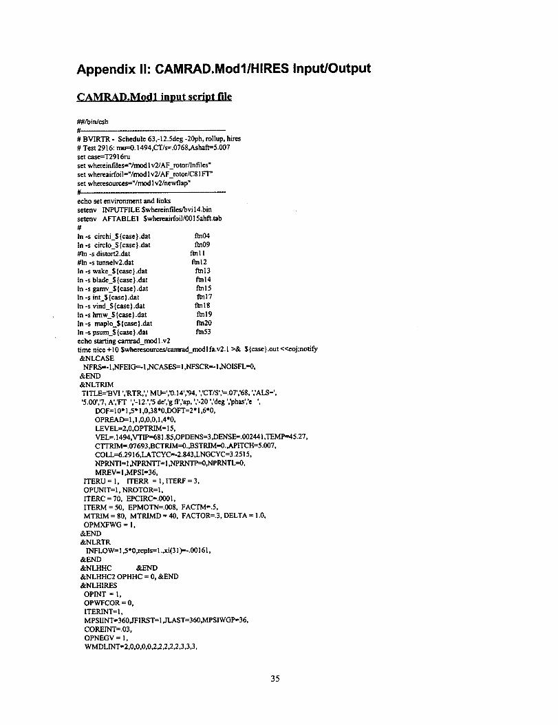
Appendix I1: CAMRAD.ModllHIRES Input/Output
CAMRAD.Modl input script file
_#/bin/csh
#
# BVIRTR - Schedule 63,-12.Sdeg -20ph, rollup, hires
# Test 2916:mu==0.1494,CT/s=.0768,Ashaff=5.007
set case=T2916ru
set whereinfiles="/rnod Iv2/AF_rotor/lnfiles"
set whereaiffoil="/mod Iv2/AF_rotor/C81 FT'
set wheresources="/mod lv2/newflap"
#.
echo set environment and links
setenv INPUTFILE Swhereinfiles/bvil4.bin
setenv AFTABLE1 $whereaiffoil/0015ahft.tab
#
In-s circhi_${case}.dat ft_04
In-s circlo_${case}.dat ft_09#In -s distort2.dat ftn I 1
#In -s tunneiv2.dat fm 12
In -s wake_$ {case } .dat fm 13
In -s blades {case }.dat ftn 14
In -s gamv_$ {case } .dat ftn 15
In -s int_$ {case } Mat fin i 7
In -s vind_$ {case } .dat ftn 18
In -s hmw_${case}.dat ftnl9
In-s maplo_${case}.dat ftn20
In -s psum_$ {case } .dat fin53
echo starting canvad_modl .v2
time nice +10 $wheresources/canvad_modlfa.v2.1 >& ${case}.out <<eoj;notify
&NLCASE
NFRS=-I ,NFEIG=-I ,NCASES=I ,NFSCR=-I ,NOISFL=0,
&END
&NLTRIM
TITLE='BVI ','RTR,',' MU=','0. ! 4','94, ','CT/S','=.07','68, ','ALS=',
'5.00','7, A','FT ','-12.','5 de','g fl','ap, 7-20 ','deg ','phas','e ',
DOF= ] 0* 1,5" ! ,0,38*0,DOFT=2* 1,6"0,
OPREAI>= 1,1,0,0,0,1,4"0,
LEVEL=2,0,OPTRIM = 15,
VEL=. ! 494,VTIP--68 I. 85,OPDENS=3 ,DENSE= .002441 ,TEMP---45.27,
CTTRIM =.07693 ,BCTRIM=O.,BSTRIM=O.,APITCH=5.007,
COLL--6.2916,LATCYC='2.843,LNGCYC=3.2515,
NPRNTI= 1 ,NPRNTT= I ,NPRNTP=0,NPRNTL=0,
MREV=l ,MPSI=36,
ITERU= 1, ITERR = I,ITERF=3,
OPUNIT= 1, NROTOR= I,
ITERC = 70, EPCIRC=.0001,
ITERM = 50, EPMOTN=.008, FACTM=.5,
MTRIM -- 80, MTRIMD = 40, FACTOR=.3, DELTA = 1.0,
OPMXFWG = 1,
&END
&NLRTR
INFLOW= 1,5 *0 ,rcpls= l.,xi(31 )=-.00 ] 61,
&END
&NLHHC &END
&NLHHC20PHHC = 0, &END
&NLHIRES
OPINT = 1,
OPWFCOR = 0,
ITERINT=I,
MPSIINT=360,JFIRST=I ,JLAST=360,MPSIWGP=36,
COREINT=.03,
OPNEGV = 1,
WMDLINT=2,0,0,0,0,2,2,2,2,2,3,3,3,
35

WIGMDLI =2,0,0,0,0_,2 _,3,3 _,
MRAINT=70,
RAEINT=
.2925, .30, .31, .32, .33, .34,
.35, .36, .37, .38, .39, .40, .41, .42, .43, .44,
.45, .46, .47, .48, .49, .50, .5 l, .52, .53, .54,
.55, .56, .57, .58, .59, .60, .61, .62, .63, .64,
.65, .66, .67, .68, .69, .70, .71, .72 ,.73, .74,
.75, .76, .77, .78, .79, .80, .81, .82, .83, .84,
.85,.86,.87,.88,.89,.90,.91,.92,.93,.94,
.95,.96,.97,.98,1.000,
KNWINT=90,
&END
&NLBED OPBED ffi 0, &END
&NLSWP &END
&NLFLAP
OPFLAPffi3,NFPRNT= 1,
OPFT= 1,OPFC=O,OPFL_0,
RFLAP=- 11 *0.,8" 1.,0.,
FDAffiO.,0.,-.4436,-2.6236,-6.2500,-9.8764,- 12.0564,5 *-12.5000,
- i 2.0564,-9.8764,-6.2500,-2.6236,-.4436,19*0.
&END
&NLWAKE
FNW = 0.,
KNW--9,
WKMODLffi2,2,2,2,2,2,2,2,2,2,3,3,3,
FACTWN = .0075,
COREWG(1) = .09, COREWG(2) = -.03,
COREWG(3) = 1.0, COREWG(4)= -1.,
COREO) =.03,CORE(2)=-.03,CORE(3) =.03, CORE(4) =-1., CORE(5)=-1.,MRG = 20, MRL = 20,
NG = 1, 2, 3, 4, 5, 6, 7, 8, 9,10,
11,12,13,14,15,16,17,18,19,20,
NL = 1,2, 3, 4, 5, 6, 7, 8, 9,10,
11 ,! 2,13,14,15,16,17,18,19,20,
&END
&NLBUR_T OPBURST = O, &END
&NLROLL
OPROLLU=3,oplowrffil ,ophiwrffil,
ICORYCB = 2,
CORELG=.3,1TERRUI_2,ITERFRU=2,
ITERLGCf 20,FLGCORG=O. 1,
NTIPFCT= I ,TIPFC0ffi.0,TIPFCffiO. 15915,0.,0.,0.,0.,0.,0.,0.,0.,0.,
NTCOR=9,TIPCORE=.01, .0167, .0233, .03, .045, .075,.!, .15, .2, 0.,
NSCOR=9,SECCORE=.01, .0167, .0233, .03, .045, .075,.1,. 15, .2, 0.,
ISP INffi I ,TAUC0ffi0.,TAUC 1ffi1.,
IRUZCORffi0, NSEARCHffi6, IRUDZffi0,
OPROLSSffiO, CROLSSXY=.!25, CROLSSZ=.125,
IFWLGC ffi 0,
IFWLGC ffi 1,
COREXP ffi 2,
&END
&NLCFD
OPCFD = 0,
OPBVI = 0,
OPBVI = 0,
PHICFD = 45.,
OPMOTN = I,
OPMOTN ffi0,
RDB = 0.449, 0.300, 0.449, 0.500, 0.446, 0.446,
BDB = 1.100, 1.100, 1.100, 1.100, 0.200, 0.200,
&END
&NLMEAS IMODEIN = 0, IAEROIN ffi 0, &END
&NLLOAD
MALOADffil, MHLOAD'_, MRLOADffi0,
NWKGMP = I, MWKGMP = 1, JWKGMP = 1, NPOLARffil,
36

NPLOT( 1)=2* 1, NPLOT(5)=3, NPLOT(I 2)-=3, NPLOT(17) = I, NPLOT(29)=3,
&END
eojexit
CAMRAD.Modl output
* COMPREHENSIVE ANALYTICAL MODEL OF ROTORCRAFT AERODYNAMICS •
* AND DYNAMICS •
* RELEASE ONE, JANUARY 1980 *
* CAMRAD.Modl, Release 1: Nov 1995 - DEC ALPHA VERSION •
* CAMRAD.Modl, Release 2: - DEC ALPHA VERSION •
******************************************************************************
READING NAMELIST NLCASE
NEW JOB, NUMBER OF CASES = 1
RESTART FILE NOT WRITTEN (RSWRT = 0)
INPUT SOURCE IS FILE (BLKDAT = 0)
INPUT FILE READ EVERY CASE (RDFILE = 1)
UNIT NUMBERS
INPUT FILE, NFDAT = 40
NUDB = 6
AIRFOIL 1 FILE, NFAFI = 41
PLOTS, NUPP = 6
AIRFOIL 2 FILE, NFAF2 = 41
RESTART FILE, NFRS = -i NAMELIST INPUT, NUIN = 5 DEBUG OUTPUT,
EIGENVALUE FILE, NFEIG = -1 PRINTED OUTPUT, NUOUT = 6 PRINTER-
SCRATCH FILE, NFSCR = -! LINEAR SYSTEMS, NULIN = 6
INPUT FILE, NAME = /hprs7/ts35537/ver2/Langley/AF__rotor/Infiles/bvi14.bin
AIRFOIL 1 FILE, NAME = Ihprs7/ts35537/ver2/Langley/AF_rotor/C81FT/OO15ahft.tab
READING INPUT FILE
READING NAMELIST NLTRIM
READING NAMELIST NLRTR (ROTOR 1)
READING NAMELIST NLHHC (ROTOR 1)
READING NAMELIST NLHHC2 (ROTOR 1)
READING NAMELIST NLHIRES (ROTOR 1)
READING NAMELlST NLBED (ROTOR l)
READING NAMELIST NLSWP (ROTOR l)
READING NAMELIST NLFLAP (ROTOR 1)
READING NAMELIST NLWAKE (ROTOR l)
READING NAMELIST NLBURST (ROTOR 1)
READING NAMELIST NLROLL (ROTOR 1)
READING NAMELISTNLMEAS (ROTOR 1)
READING NAMELIST NLLOAD (ROTOR 1)
READING AIRFOIL TABLES
ICOMPREHENSIVE ANALYTICAL MODEL OF ROTORCRAFT AERODYNAMICS AND DYNAMICS
*********************
CASE NUMBER 1 (NEW JOB), IDENTIFICATION =
2 GOV, 3 TO TRIM BOTH GOVERNORS), OPGOVT = 0
37
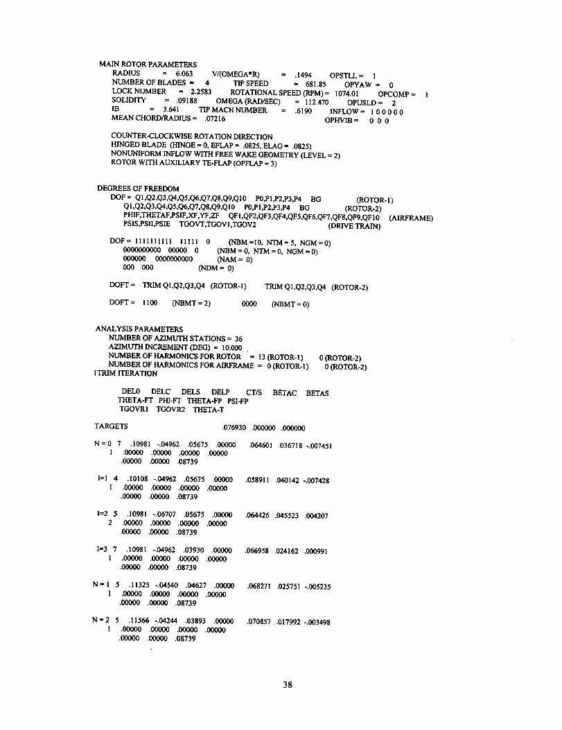
MAIN ROTOR PARAMETERS
RADIUS = 6.063 V/(OMEGA*R) = .1494 OPSTLL = !
NUMBER OF BLADES = 4 TIP SPEED = 681.85 OPYAW = 0
LOCKNUMBER =, 2.2583 ROTATIONAL SPEED (RPM)= 1074.01 OPCOMP = 1
SOLIDITY = .09188 OMEGA (RAD/SEC) = 112.470 OPUSLD = 2
IB = 3.641 TIP MACH NUMBER = .6190 INFLOW = 1 0 0 0 0 0
MEAN CHORD/RADIUS= .07216 OPHVIB = 0 0 0
COUNTER-CLOCKWISE ROTATION DIRECTION
HINGED BLADE (HINGE = 0, EFLAP = .0825, ELAG = .0825)
NONUNIFORM INFLOW WITH FREE WAKE GEOMETRY (LEVEL =, 2)
ROTOR WITH AUXILIARY TE-FLAP (OPFLAP = 3)
DEGREES OF FREEDOM
DOF= QI,Q2,Q3,Q4,Q5,Q6,Q7,QS,Q9,QIO PO,Pl,P2,P3,P4 BG (ROTOR-I)
QI,Q2,Q3,Q4,Q5,Q6,Q7,Q8,Q9,QlO PO,PI,P2,P3,p4 BG (ROTOR-2)
PHIF,THETAF,PSIF,XF,YF,ZF QFI,QF2,QF3,QF4,QFS,QF6,QFT,QFS,QF9,QFIO (AIRFRAME)
PSIS,PSII,PSIE TGOVT,TGOVI,TGOV2 (DRIVE TRAIN)
IX)F= 1111111111 IIIll 0 (NBM=I0, NTM=5, NGM=0)000000(O_ 00000 0 (NBM = 0, NTM = 0, NGM = 0)oooooo oooooooo_ (HAM = 0)000 000 (NDM = 0)
DOFT= TRIMQI,Q2,Q3,Q4 (ROTOR-I) TRIMQ1,Q2,Q3,Q4 (ROTOR-2)
DOFT= !100 (NBMT = 2) 0000 (NBMT = 0)
ANALYSIS PARAMETERS
NUMBER OF AZIMUTH STATIONS -- 36
AZIMUTH INCREMENT (DEG) .= 10.000
NUMBER OF HARMONICS FOR ROTOR = 13 (ROTOR-I)
NUMBER OF HARMONICS FOR AIRFRAME = 0 (ROTOR-l)
1TRIM ITERATION
0 (ROTOR-2)
0 (ROTOR-2)
DEL0 DELC DELS DELP CT/S BETAC BETAS
THETA-FT PHI-FT THETA-FP PSI-F9
TGOVRi TGOVR2 THETA-T
TARGETS .076930 .000000 .000000
N = 0 7 .10981 -.04962 .05675 .00000 .064601 .036718 -.007451
1 .00000 .00000 ,00000 .00000
.00000 .00000 .08739
I=1 4 .10108 -.04962 .05675 .00000 .058911 .040142 -.007428
I .00000 .00000 .00000 .00000
•00000 .00000 .08739
I=2 5 .i0981 -.06707 .05675 .00000 .064426 .045523 .004207
2 .00000 .00000 .00000 .00000
.000_ .00000 .08739
I=3 7 .10981 -.04962 .03930 .00000 .066958 .024162 .000991
1 .00000 .00000 .000_ .00000
.00000 .00000 .08739
N= 1 5 .11325 -.04540 .04627 .0(X)_ .068271 .025751 -.005235
1 .00000 .00000 .00000 .00000
.00000 .00000 .08739
N = 2 5 .11566 -.04244 .03893 .00000 .070857 .017992 -.003498
I .00000 .00000 .00000 .00000
.00000 .00000 .08739
38

N=I6 1 .12104 -.03516 .02175 .00000 .076928 .000130 -.000022
1 .00000 .00000 .00000 .00000
•00000 .00000 .08739
AIRCRAFT TRIM
UNIFORM INFLOW
WAKE/TRIM ITERATION NUMBER 1 (MAXIMUM = 1)
NUMBER OF TRIM ITERATION = 16 (MAXIMUM = 80, TOLERANCE = .00050)
WIND TUNNEL, TR1M OPTION NUMBER 15
FORCES
TRIMMED TARGET ERROR
** CT/S
CP/S
CL/S
CX/S
CY/S
** BETAC
** BETAS
.0769279 .0769300 .0000279 **
.0044236 .0000000 .0000000
.0765662 .0000000 .0000000
.0077109 .0000000 .0000000
-.0017141 .0000000 .0000000
.0075 .0000 .0001302 **
-.0012 .0000 .0000218 **
CONTROL
TRIMMED INPUT
** DEL0 = 6.93 COLL = 6.29"*
** DELC = -2.01 LATCYC = -2.84 **
** DELS = 1.25 LNGCYC= 3.25'*
THETA-T= 5.01 APITCH= 5.01
PSI-T = .00 AYAW = .00
COLLECTIVE CONTROLS - DEL0 = 6.93 TGOVRI= .00 TGOVR2= .00
THROTTLE CONTROLS -DELT= ,00 C-T = .00
AIRCRAFT CONTROLS -DELF = .00 DELE = .00 DELA = .00 DELR= .00
ROTOR CONTROLS --T75 = 6.93 TIC = 2.01 T1S = -1.25
1TRIM ITERATION
DEL0 DELC DELS DELP CT/S BETAC BETAS
THETA-FT PHI-FT THETA-FP PSI-FP
TGOVR1 TGOVR2 THETA-T
TARGETS .076930 .000000 .000000
N=0 70 .12104 -.03516 .02175 .00000 .094398 .002656 .011099
1 .00000 .00000 .00000 .00000
.00000 .00000 .08739
*** CIRCULATION NOT CONVERGED ***
l=l 4 .11231 -.03516 .02175 .00000 .084017 .006468 .010205
I .00000 .00000 .00000 .00000
.00000 .00000 .08739
I=2 3 .12104 -.05261 .02175 .00000 .094291 .008834 .026215
1 .00000 .00000 .00000 .00000
.00000 .00000 .08739
I=3 25 .12104 -.03516 .00430 .00000 .096115 -.013389 .015340
1 .00000 .00000 .00000 .00000
.00000 .00000 .08739
N= 1 4 .11648 -.03141 .02016 .00000 .086401 .002119 .005998
I .00000 .00000 .00000 .00000
.00000 .00000 .08739
N = 2 2 .i1399 -.02932 .01909 .00000 .083671 .001501 .004222
1 .00000 .00000 .00000 .00000
.00000 .00000 .08739
N=23 1 .10755 -.02486 .01637 .00000 .076965 -.000024 -.000042
39

1 .00000 .00000 .000(30 .00000.00000 .00000 .08739
I****_********
AIRCRAFT TRIM*********OS**
NONUNIFORM INFLOW WITH PRESCRIBED WAKE GEOMETRYWAKE/TRIM ITERATION NUMBER 1 (MAXIMUM = I)
NUMBER OF TRIM ITERATION = 23 (MAXIMUM = 80, TOLERANCE = .00050)WIND TUNNEL, TRIM OPTION NUMBER 15
FORCES CONTROL
** CT/S
CP/SCL/S
CX/SCY/S
** BETAC** BETAS
TRIMMED TARGET ERROR.0769653 .0769300 .0004583 **
.0035783 .0000000 .0000000.0765413 .0000000 .0000000.0083068 .0000000 .0000000
-.0011750 .0000000 .0000000-.0013 .0000 .0000236 **-.0024 .0000 .0000421 **
TRIMMED INPUT**DEL0 = 6.16 COLL = 6.29**
** DELC = -1.42 LATCYC= -2.84"***DELS = .94 LNGCYC= 3.25"*
THETA-T = 5.01 APITCH -- 5.01
PSI-T = .00 AYAW = .00
COLLECTIVE CONTROLS - DEL0 = 6.16 TGOVRI= .00 TGOVR2= .00THROTTLE CONTROLS - DELT --- .00 C-T = .00
AIRCRAFT CONTROLS -DELF= .00 DELE = .00 DELA = .00 DELR= .00ROTOR CONTROLS -1"75 = 6.16 TIC = 1.42 T1S = -.94
ITRIM ITERATION
DEL0 DELC DELS DELP CT/S BETAC BETASTHETA-FT PHI-FT THETA-FP PSI-FPTGOVR! TGOVR2 THETA-T
TARGETS .076930 .000000 .000000
N= 0 50 .10755 =.02486 .01637 .00000 .075840 .001434 -.0109331 .00000 .00OO(3 .00000 .00000
.00000 .00000 .08739
I=1 3 .09882 -.02486 .01637 .00000 .065890 .004945 -.011459] .00000 .00000 .000_ .00000
.00000 .00000 .08739
I=2 5 .I0755 -.04231 .01637 .00000 .076267 ,007623 .004512
l .00000 .00000 .00000 .00000•00000 .00000 .08739
I=3 4 .I0755 -.02486 -.00108 .00000 .080635-.014739-.005311
I .00000 .00000 .00000 .00000.00000 .00000 .08739
N = 1 3 .10735 -.02795 .01464 .00000 .076259 .001139 -.007923! .00000 .00000 .00000 .00000
.00000 .00000 .08739
N=2 3 .I0716 -.03017 .01333 .00000 .076373 .000794-.005578I .00000 .0000(3 .00000 .00000
.00000 .00000 .08739
N=21 I .10708 -.03572 .00994 .00000 .076893 .000058-.000080
I .00000 .00000 .00000 .00000
.00000 .00000 .08739l*************
AIRCRAFT TRIM
40

NONUNIFORM INFLOW WITH FREE WAKE GEOMETRY
WAKEfFRIM ITERATION NUMBER 1 (MAXIMUM= 3)
NUMBER OF TRIM ITERATION = 21 (MAXIMUM = 80, TOLERANCE = .00050)
WIND TUNNEL, TRIM OPTION NUMBER 15
FORCES
TRIMMED TARGET ERROR
** CT/S
CP/S
CL/S
CX/S
CY/S
** BETAC
** BETAS
.0768928 .0769300 .0004836 **
.0035185 .0000000 .0000000
.0764978 .0000000 .0000000
.0080405 .0000000 .0000000
-.0015103 .0000000 .0000000
.0033 .0000 .0000576 **
-.0046 .0000 .0000799 **
CONTROL
TRIMMED INPUT
** DEL0 = 6.14 COLL ffi 6.29"*
** DELC = -2.05 LATCYC = -2.84 **
** DELS ffi .57 LNGCYCffi 3.25"*
THETA-T= 5.01 APITCH= 5.01
PSI-T = .00 AYAW = .00
COLLECTIVE CONTROLS - DEL0 = 6.14 TGOVRI= .00 TGOVR2= .00
THROTTLE CONTROLS -DELT= .00 C-T = .00
AIRCRAFT CONTROLS -DELF= .00 DELE = .00 DELA = .00 DELR= .00
ROTOR CONTROLS -T75 = 6.14 T1C -- 2.05 TIS = -.57
1TRIM ITERATION
DEL0 DELC DELS DELP CT/S BETAC BETAS
THETA-FT PHI-F'I" THETA-FP PSI-FP
TGOVRI TC__K)VR2 THETA-T
TARGETS •076930 .000000 .000000
N f0 3 .10708 -.03572 .00994 .00000
1 .00000 .00000 .00000 .00000
.00000 .00000 .08739
.076487 -.000135 -.000394
1=1 3 .09836-.03572 .00994 .00000
1 .00000 .00000 .00000 .00000
.00000 .00000 .08739
.066198 .003553 -.000924
lffi2 3 .10708 -.05318 .00994 .00000
! .00000 .00000 .00000 .00000
.00000 .00000 .08739
•076627 .006197 .015196
1=3 3 .10708 -.03572 -.00751 .00000
1 .00000 .00000 .00000 .00000
.00000 .00000 .08739
•081030 -.016089 .005343
N= 1 3 .10720 -.03586 .00999 .00000
1 .00000 .00000 .00000 .00000
.00000 .00000 .08739
.076609 .000268 -.000453
N=2 1 .10726 -.03597 .00988 .00000
1 .00000 .00000 .00000 .00000
.00000 .00000 .08739
.076713 .000194 -.000326
N _l I 1 .10741 -.03630 .00957 .00000
1 .00000 .00000 .00000 .00000
.00000 .00000 .08739
AIRCRAFT TRIM***S*****O**J
•076893 .000038 -.000064
NONUNIFORM INFLOW WITH FREE WAKE GEOMETRY
41

WAKE/TRIM ITERATION NUMBER 2 (MAXIMUM = 3)
NUMBER OF TRIM ITERATION = 11 (MAXIMUM -- 80, TOLERANCE = .00050)
WIND TUNNEL, TRIM OPTION NUMBER 15
FORCES
TRIMMED TARGET ERROR
** CWS
CP/S
CL/S
CX/S
CY/S
** BETAC
** BETAS
.0768932 .0769300 .0004779 **
.0035437 .0000000 .0000000
.0764944 .0000000 .0000000
.0080863 .0000000 .0000000
-.0015205 .0000000 .0000000
.0022 .0000 .0000383 **
-.0037 .0000 .0000638 **
CONTROL
TRIMMED INPUT
**DEL0 = 6.15 COLL = 6.29"*
** DELC = -2.08 LATCYC = -2.84 **
**DELS = .55 LNGCYC= 3.25"*
THE]A-T= 5.01 APITCH_- 5.01
PSI-T = .00 AYAW = .00
COLLECTIVE CONTROLS - DEL0 -- 6.15 TGOVRI= .00 TGOVR2-- .00
THROTTLE CONTROLS - DELT = .00 C-T = .00
AIRCRAFT CONTROLS -DELF-- .00 DELE = .00 DELA = .00 DELR= .00
ROTOR CONTROLS -'I"75 _ 6.15 TIC -- 2.08 TIS = -.55
1TRIM ITERATION
DELO DELC DELS DELP CT/S BETAC BETAS
THETA-FT PHI-FT THETA-FP PSI-FP
TGOVRl TGOVR2 THETA-T
TARGETS .076930 .000000 .000000
N = 0 2 .10741 -.03630 .00957 .00000 .076895 .000016 .000030
1 .00000 .00000 ,00000 .00000
.00000 .00000 .08739
I--I 3 .09869-.03630 .00957 .00000 .066610 .003687-.000507
I .00000 .00000 .00000 .00000
.00000 .00000 .08739
I--2 3 .10741 -.05376 .00957 .00000 .077040 .006314 .015633
I .00000 .00000 .00000 .00000
.00000 .00000 .08739
I=3 3 .10741 -.03630 -.00788 .00000 ,081437 -.015979 .005784
1 .00000 .00000 .00000 .00000
.00000 .00000 .08739
N = I 3 .10742 -.03629 .00957 .00000 .076897 .000315 -.000130
1 .00000 .00000 .00000 .00000
.00000 .00000 .08739
STARTING ROLLUP INITIALIZATION
ROLLUP CONVERGENCE LOOP ITERATION NUMBER 1
STARTING LARGE CORE LOADS ITERATION NUMBER 1
STARTING LARGE CORE LOADS ITERATION NUMBER 2
STARTING LARGE CORE LOADS ITERATION NUMBER 3
STARTING LARGE CORE LOADS ITERATION NUMBER 4
STARTING LARGE CORE LOADS ITERATION NUMBER 5
STARTING LARGE CORE LOADS ITERATION NUMBER 6
STARTING LARGE CORE LOADS ITERATION NUMBER 7
STARTING LARGE CORE LOADS ITERATION NUMBER 8
STARTING LARGE CORE LOADS ITERATION NUMBER 9
STARTING LARGE CORE LOADS ITERATION NUMBER I0
STARTING LARGE CORE LOADS ITERATION NUMBER 11
STARTING LARGE CORE LOADS ITERATION NUMBER 12
STARTING LARGE CORE LOADS ITERATION NUMBER 13
STARTING LARGE CORE LOADS ITERATION NUMBER 14
STARTING LARGE CORE LOADS ITERATION NUMBER 15
STARTING LARGE CORE LOADS ITERATION NUMBER i 6
STARTING LARGE CORE LOADS ITERATION NUMBER 17
42

STARTING LARGE CORE LOADS ITERATION NUMBER 18
STARTING LARGE CORE LOADS ITERATION NUMBER 19
STARTING LARGE CORE LOADS ITERATION NUMBER 20
POINT OMITTED IN YBAR CALCULATION AT PSi = 60.0
IRYBAR= 2 YBAR= -.014438 RYBAR= .030000 GAMMA= .002157
POINT OMITTED IN YBAR CALCULATION AT PSI = 60.0
IRYBAR= 3 YBAR= -.022850 RYBAR = .050000 GAMMA= .001868
POINT OMITTED IN YBAR CALCULATION AT PSI = 60.0
IRYBAR= 4 YBAR = -.018743 RYBAR = .070000 GAMMA = .001966
POINT OMI1TED IN YBAR CALCULATION AT PSI = 60.0
IRYBAR = 5 YBAR= -.007013 RYBAR= .090000 GAMMA= .002231
POINT OMITTED IN YBAR CALCULATION AT PSI = 60.0
IRYBAR= 2 YBAR= -.042418 RYBAR= .112500 GAMMA= .002687
POINT OMITYED IN YBAR CALCULATION AT PSI = 60.0
IRYBAR= 3 YBAR= -.005432 RYBAR= .137500 GAMMA= .003449
POINT OMI'ITED IN YBAR CALCULATION AT PSI = 70.0
IRYBAR= 2 YBAR= -.012141 RYBAR= .030000 GAMMA= .002735
POINT OMITI'ED IN YBAR CALCULATION AT PSl = 70.0
IRYBAR= 3 YBAR = -.026749 RYBAR= .050000 GAMMA = .002137
POINT OMITTED IN YBAR CALCULATION AT PSI = 70.0
IRYBAR= 4 YBAR= -.037195 RYBAR= .070000 GAMMA= .001907
POINT OMITTED IN Y'BAR CALCULATION AT PSI = 70.0
IRYBAR= 5 YBAR= -.038642 RYBAR= .090000 GAMMA= .001884
POINT OMITTED IN YBAR CALCULATION AT PSI = 70.0
IRYBAR= 6 YBAR= -.022276 RYBAR= .112500 GAMMA = .002133
POINT OMITTED IN YBAR CALCULATION AT PSI = 70.0
IRYBAR= 2 YBAR= -.072375 RYBAR= .137500 GAMMA=
POINT OMITTED IN YBAR CALCULATION
IRYBAR = 3 YBAR = -.007371 RYBAR =
POINT OMITTED IN YBAR CALCULATION
IRYBAR= 2 YBAR = -.015517 RYBAR=
POINT OMITTED IN YBAR CALCULATION
IRYBAR= 3 YBAR = -.035851 RYBAR=
POINT OMITTED IN YBAR CALCULATION
IRYBAR= 4 YBAR= -.051804 RYBAR=
POINT OMITTED IN YBAR CALCULATION
IRYBAR = 5 YBAR = -.054704 RYBAR =
POINT OMITTED IN YBAR CALCULATION
IRYBAR = 6 YBAR = -.034570 RYBAR =
POINT OMITTED IN YBAR CALCULATION
IRYBAR= 2 YBAR= -.095919 RYBAR=
POINT OMITI'ED IN YBAR CALCULATION
AT PSI = 70.0
.162500 GAMMA =
AT PSI = 80.0
.030000 GAMMA =
AT PSI = 80.0
.050000 GAMMA =
AT PSI = 80.0
.070000 GAMMA =
AT PSI = 80.0
.090000 GAMMA =
AT PSI = 80.0
.I 12500 GAMMA =
AT PSl = 80.0
.137500 GAMMA=
AT PSI = 80.0
.002758
.003897
.002405
.001760
.001509
.001476
.001695
.002307
.003443
.001438
.000704
IRYBAR= 3 YBAR= -.014812 RYBAR= .162500 GAMMA=
POINT OMITTED IN YBAR CALCULATION AT PSI = 89.99999
IRYBAR= 2 "YBAR= -.031635 RYBAR= .030000 GAMMA=
POINT OMITTED IN YBAR CALCULATION AT PSI = 89.99999
IRYBAR= 3 YBAR = -.106202 RYBAR= .050000 GAMMA=
POINT OMITTED IN YBAR CALCULATION AT PSI = 89.99999
IRYBAR= 4 YBAR= -.208351 RYBAR= .070000 GAMMA= .000436
POINT OMITTED IN YBAR CALCULATION AT PSI = 89.99999
IRYBAR = 5 YBAR = -.211345 RYBAR = .090000 GAMMA = .000432
POINT OMITTED IN YBAR CALCULATION AT PSI = 89.99999
IRYBAR= 6 YBAR= -.086442 RYBAR= .112500 GAMMA= .000719
POINT OMITTED IN YBAR CALCULATION AT PSI = 89.99999
IRYBAR= 2 YBAR= -.163844 RYBAR= .137500 GAMMA= .001432
POINT OMITTED IN YBAR CALCULATION AT PSI = 89.99999
IRYBAR= 3 YBAR= -.020153 RYBAR= .162500 GAMMA= .002641
POINT OMITTED IN YBAR CALCULATION AT PSI = 99.99999
IRYBAR= 2 YBAR= -.044538 RYBAR= .030000 GAMMA= .001072
POINT OMITI'ED IN YBAR CALCULATION AT PSI = 99.99999
GAMMA = .000313
99.99999
GAMMA = .000397
99.99999
GAMMA = .001173
99.99999
GAMMA = .002430
IRYBAR= 3 YBAR= -.249216 RYBAR= .050000
POINT OMITTED IN YBAR CALCULATION AT PSI =
IRYBAR= 4 YBAR= -.179203 RY'BAR= .112500
POINT OMITTED IN YBAR CALCULATION AT PSI =
IRYBAR= 2 YBAR= -.196566 RYBAR= .137500
POINT OMITTED IN Y'BAR CALCULATION AT PSI =
IRYBAR= 3 YBAR = -.017262 RYBAR= .162500
43

POINT OMITTED IN YBAR CALCULATION AT PSI = 110.0
IRYBAR -- 2 YBAR = =.042342 RYBAR == .030000 GAMMA = .001101
POINT OMITTED IN YBAR CALCULATION AT PSI - 110.0
IRYBAR= 3 YBAR= -.177778 RYBAR _= .050000 GAMMA= .000416
POINT OMITTED IN YBAR CALCULATION AT PSI = 110.0
IRYBAR = 4 YBAR = -.360546 RY'BAR == .070000 GAMMA = .000235
POINT OMITI'ED IN YBAR CALCULATION AT PSI = 1 I0.0
IRYBAR = 5 YBAR = -.240340 RYBAR = .090000 GAMMA = .000324
POINT OMITTED IN YBAR CALCULATION AT PSI = 110.0
IRYBAR = 6 YBAR = -.046814 RYBAR = .! 12500 GAMMA = .000747
POINT OMITTED IN YBAR CALCULATION AT PSI = 110.0
IRYBAR= 2 YBAR= -.127736 RYBAR == .137500 GAMMA= .001561
POINT OMITTED IN YBAR CALCULATION AT PSI = 110.0
IRYBAR= 3 YBAR= -.003896 RYBAR= .162500 GAMMA= .002818
POINT OMITTED IN YBAR CALCULATION AT PSI = 120.0
IRYBAR= 2 Y'BAR= -.121720 RY'BAR= .030000 GAMMA= .000440
POINT OMITTED IN YBAR CALCULATION AT PSI = 120.0
IRYBAR= 6 YBAR = -.088442 RYBAR= .112500 GAMMA= .000272
POINT OMITTED IN YBAR CALCULATION AT PSI = 140.0
IRYBAR= 3 YBAR= -.118036 RYBAR= .090000 GAMMA= .000362
STARTING ROLLUP WAKE-TRIM ITERATION NUMBER i
before wakecl, wake-trim iteration # !
aPter wakecl, wake-trim iteration # 11 TRIM ITERATION
DEL0 DELC DELS DELP CT/S
THETA-FT PH|-FT THETA-FP PSI-FP
TC_K)VR1 TGOVR2 THETA-T
BETAC BETAS
TARGETS .076930 .000000 .000000
N = 0 70 .10742 -.03629 .00957 .00000 .090126 .000416 .016829
! .00000 .00000 .00000 .00000
.000(30 .00000 .08739
*** CIRCULATION NOT CONVERGED ***
I_=1 30 .09870 -.03629 .00957 .00000
1 .00000 .00000 .00000 .00000
.00000 .00000 .08739
.081061 .004315 .016113
1=2 3 .10742 -.05375 .00957 .00000
l .00000 .00000 .00000 .00000
.00000 .000(30 .08739
.091156 .007426 .032023
I--3 4 .10742 -.03629 -.00788 .00000
! ,00000 .00000 .00000 .00000
.000_ .00000 .08739
.095609 -.014808 .022553
N= 1 3 .10408 -.03102 .01015 .00000
i .00000 .00000 .00000 .00000
.00000 .00000 .08739
.087123 .001365 .011616
N=2 3 .10131 -.02723 .01000 .00000
1 .00000 .00000 .00000 .00000
.00000 .00000 .08739
.083943 .000945 .008143
N =34 I .09455 -.01843 DI019 .00000
I .00000 .00000 .00000 .00000
.00000 .00000 .08739
I***********'0
AIRCRAFT TRIM
.076968 -.000034 .000000
44

NONUNIFORM INFLOW WITH FREE WAKE GEOMETRY
WAKE/TRIM ITERATION NUMBER 1 (MAXIMUM = 2)
NUMBER OF TRIM ITERATION = 34 (MAXIMUM = 80, TOLERANCE = .00050)
WIND TUNNEL, TRIM OPTION NUMBER 15
FORCES CONTROL
** CT/S
CP/S
CL/S
CX/S
CWS
** BETAC
** BETAS
TRIMMED TARGET ERROR
.0769680 .0769300 .0004935 **
.0027949 .0000000 .0000000
.0765692 .0000000 .0000000
.0079516 .0000000 .0000000
-.0006835 .0000000 .0000000
-.0019 .0000 .0000338 **
.0000 .0000 .0000003 **
TRIMMED INPUT
** DEL0 = 5.42 COLL = 6.29"*
**DELC = -I.06 LATCYC= -2.84"*
**DELS = .58 LNGCYC= 3.25"*
THETA-T = 5.01 APITCH = 5.01
PSI-T = .00 AYAW = .00
COLLECTIVE CONTROLS - DEL0 = 5.42 TGOVRI= .00 TGOVR2= .00
THROTTLE CONTROLS -DELT= .00 C-T = .00
AIRCRAFT CONTROLS -DELF= .00 DELE = .00 DELA = .00 DELR= .00
ROTOR CONTROLS -1"75 = 5.42 TIC = !.06 T1S = -.58
STARTING ROLLUP WAKE-TRIM ITERATION NUMBER 2
before wakecl, wake-trim iteration # 2
after wakecl, wake-Uim iteration # 21TRIM ITERATION
DEL0 DELC DELS DELP CT/S BETAC BETAS
THETA-FT PHI-FT THETA-FP PSI-FP
TGOVRI TGOVR2 THETA-T
TARGETS .076930 .000000 .000000
N= 0 2 .09455 -.01843 .01019 .00000 .077094 -.000164 .000270
1 .00000 .00000 .00000 .00000
.00000 .00000 .08739
I=1 15 .08582 -.01843 .01019 .00000 .067630 .002989 -,000474
1 .00000 .00000 .00000 .00000
.00000 .00000 .08739
I=2 3 .09455 -.03589 .01019 .00000 .077952 .005730 .015537
1 .00000 .00000 .00000 .00000
.00000 .00000 .08739
I=3 3 .09455-.01843 -.00726 .00000 .082512-.016688 .005873
i .00000 .00000 .00000 .00000
.00000 .00000 .08739
N= 1 3 .09453 -.01837 .01026 .00000 .077895 -.000245 -.000049
1 .00000 .00000 .00000 .00000
.00000 .00000 .08739
N = 2 6 .09425 -.01840 .01022 .00000 .077576 -.000200 -.000016
I .000130 .00000 .00000 .00000
.00000 .00000 .08739
N =10 1 .09373 -.01845 .01024 .00000 .076961 -.000033 .000002
! .00000 .00000 .00000 .00000
.00000 .00000 .08739
AIRCRAFT TRIM
45

NONUNIFORM INFLOW WITH FREE WAKE GEOMETRY
WAKE/TRIM ITERATION NUMBER 2 (MAXIMUM -- 2)
NUMBER OF TRIM ITERATION = I0 (MAXIMUM = 80, TOLERANCE = .00050)WIND TUNNEL, TRIM OPTION NUMBER 15
FORCES CONTROL
TRIMMED TARGET ERROR
** CT/S .0769613 .0769300 .0004064 **
CP/S .0027963 .0000000 .0000000
CL/S .0765622 .0000000 .0000000
CX/S .0079548 .0000000 .0000000
CY/S -.0006901 .0000000 .0000000
** BETAC -.0019 .0000 .0000334 **
** BETAS .0001 .0000 .0000024 **
TRIMMED INPUT
**DEL0 -- 5.37 COLL = 6.29**
** DELC = -1.06 LATCYC= -2.84"*
** DELS = .59 LNGCYC= 3.25"*
THETA-T= 5.01 APITCH= 5.01
PSI-T = .00 AYAW -- .00
COLLECTIVE CONTROLS - DEL0 = 5.37 TGOVRI= .00 TGOVR2= .00
THROTTLE CONTROLS - DELT = .00 C-T = .00
AIRCRAFT CONTROLS -DELl:= .00 DELE = .00 DELA = .00 DELR=
ROTOR CONTROLS -T75 = 5.37 TIC = 1.06 TIS = -.59
ROLLUP CONVERGENCE LOOP ITERATION NUMBER 2
STARTING LARGE CORE LOADS ITERATION NUMBER 1
STARTING LARGE CORE LOADS ITERATION NUMBER 2
STARTING LARGE CORE LOADS ITERATION NUMBER 3
STARTING LARGE CORE LOADS ITERATION NUMBER 4
STARTING LARGE CORE LOADS ITERATION NUMBER 5
STARTING LARGE CORE LOADS ITERATION NUMBER 6
STARTING LARGE CORE LOADS ITERATION NUMBER 7
STARTING LARGE CORE LOADS ITERATION NUMBER 8
STARTING LARGE CORE LOADS ITERATION NUMBER 9
STARTING LARGE CORE LOADS ITERATION NUMBER 10
STARTING LARGE CORE LOADS ITERATION NUMBER 11
STARTING LARGE CORE LOADS ITERATION NUMBER 12
STARTING LARGE CORE LOADS ITERATION NUMBER 13
STARTING LARGE CORE LOADS ITERATION NUMBER 14
STARTING LARGE CORE LOADS ITERATION NUMBER 15
STARTING LARGE CORE LOADS ITERATION NUMBER 16
STARTING LARGE CORE LOADS ITERATION NUMBER 17
STARTING LARGE CORE LOADS ITERATION NUMBER 18
STARTING LARGE CORE LOADS ITERATION NUMBER 19
STARTING LARGE CORE LOADS ITERATION NUMBER 20
POINT OMITTED 1N YBAR CALCULATION AT PSI = 49.99999
IRYBAR= 2 YBAR-- -.144202 RYBAR= .030000 GAMMA= .000208
POINT OMITTED IN YBAR CALCULATION AT PSI = 49.99999
IRYBAR= 3 YBAR= -.150532 RYBAR= .050000 GAMMA= .000201
POINT OMITTED IN YBAR CALCULATION AT PSI = 49.99999
IRYBAR = 4 YBAR-- -.009869 RYBAR = .070000 GAMMA = .000607
POINT OMITrED IN YBAR CALCULATION AT PSI = 49.99999
IRYBAR= 2 YBAR= -.036681 RYBAR= .090000 GAMMA= .001184
POINT OMITTED IN YBAR CALCULATION AT PSI = 60.0
IRYBAR = 7 YBAR = -.395045 RYBAR = .137500 GAMMA = -.000262
POINT OMITTED IN YBAR CALCULATION AT PSI = 99.99999
IRYBAR= 2 YBAR-- -.174101 RYBAR= .030000 GAMMA= .000323
POINT OMITTED IN YBAR CALCULATION AT PSI = 110.0
IRYBAR= 2 Y'BAR= -.144321 RYBAR-- .030000 GAMMA= .000382
POINT OMITFED IN YBAR CALCULATION AT PSI = I I0.0
IRYBAR= 6 YBAR= -.040106 RYBAR-- .137500 GAMMA= .000272
POINT OMITTED IN YBAR CALCULATION AT PSI = 120.0
IRYBAR-- 7 YBAR= -.103617 RYBAR= .137500 GAMMA= -.000239
POINT OMITTED IN YBAR CALCULATION AT PSI = 130.0
IRYBAR= 7 YBAR= -.115570 RYBAR= .137500 GAMMA= -.000518
STARTING ROLLUP WAKE-TRIM ITERATION NUMBER
before wakec 1, wake-trim iteration # 1
afterwakecl, wake-trim iteration # I
ITRIM ITERATION
.00
46
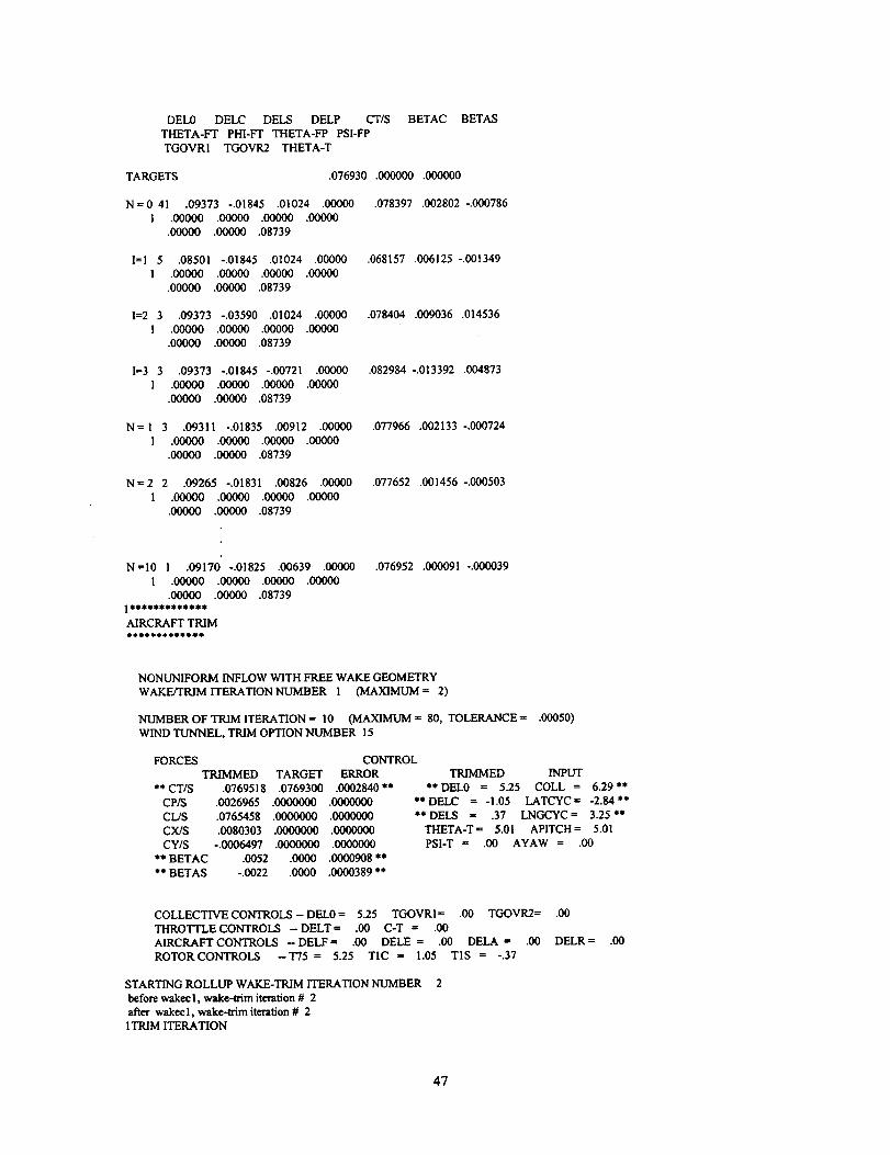
DEL0 DELC DELS DELP CT/S BETAC BETAS
THETA-FT PHI-FT THETA-FP PSI-FP
TGOVR1 TGOVR2 THETA-T
TARGETS .076930 .000000 .000000
N = 0 41 .09373 -.01845 .01024 .00000 .078397 .002802 -.000786
1 .00000 .00000 .00000 .00000
.00000 .00000 .08739
I=1 5 .08501 -.01845 .01024 .00000 .068157 .006125 -.001349
1 .00000 .00000 .00000 .00000
.00000 .00000 .08739
I=2 3 .09373 -.03590 .01024 .00000 .078404 .009036 .014536
1 .00000 .00000 .00000 .00000
.00000 .00000 .08739
I=3 3 .09373 -.01845 -.00721 .00000 .082984 -.013392 .004873
1 .00000 .001300 .00000 .00¢X_
.00000 .00000 .08739
N = I 3 .09311 -.01835 .00912 .00000 .077966 .002133 -.000724
1 .00000 .00000 .00000 .00000
.00000 .00000 .08739
N = 2 2 .09265 -.01531 .00826 .00000 .077652 .001456 -.000503
1 .00000 .00000 .00000 .00000
.00000 .00000 .08739
N =10 1 .09170 -.01825 .00639 .00000 .076952 .000091 -.000039
I .00000 .00000 .00000 .00000
.00000 .00000 .08739
AIRCRAFT TRIM
NONUNIFORM INFLOW WITH FREE WAKE GEOMETRY
WAKE/TRIM ITERATION N-UMBER 1 (MAXIMUM = 2)
NUMBER OF TRIM ITERATION = 10 (MAXIMUM = 80, TOLERANCE = .00050)
WIND TUNNEL, TRIM OPTION NUMBER 15
FORCES CONTROL
** CT/S
CP/S
CL/S
CX/S
CY/S
** BETAC
** BETAS
TRIMMED TARGET ERROR
.0769518 .0769300 .0002840 **
.0026965 .0000000 .0000000
.0765458 .0000000 .0000000
.008O303 .0000000 .0000000
-.0006497 .0000000 .0000000
.0052 .0000 .0000908 **
-.0022 .0000 .0000389 **
TRIMMED INPUT
**DEL0 = 5.25 COLL = 6.29"*
**DELC = -I.05 LATCYC= -2.84"*
**DELS = .37 LNGCYC= 3.25"*
THETA-T= 5.01 APITCH= 5.01
PSI-T = .00 AYAW = .00
COLLECTIVE CONTROLS - DEL0 = 5.25 TGOVRI= .00 TGOVR2= .00
THROTTLE CONTROLS - DELT = .00 C-T = .00
AIRCRAFT CONTROLS -DELF= .00 DELE = .IX) DELA = .00 DELR= .00
ROTOR CONTROLS -T75 = 5.25 TIC = 1.05 T1S = -.37
STARTING ROLLUP WAKE-TRIM ITERATION NUMBER 2
before wake¢i, wake-trim iteration # 2
after wakecl, wake-lrim iteration # 2
! TRIM ITERATION
47
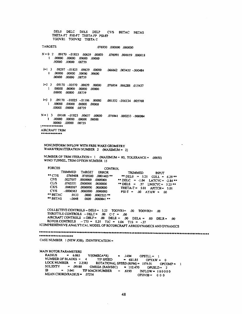
DEL0 DELCDELS DELP CT/S
THETA-FT PHI-FT THETA-FP PSI-FP
TGOVR1 TGOVR2 THETA-T
BETAC BETAS
TARGETS .076930 .000000 .000000
N=0 2 .09170 -.01825 .00639 .00000
I .00000 .00000 .00000 .00000
.00000 .00000 .08739
.076991 .000059 .00001 $
I=I 3 .08297-.01825 .00639 .00000
1 .00000 .00000 .00000 .00000
.00000 .00000 .08739
.066662 .003432 -.00048.4
I=2 3 .09170 -.03570 .00639 .00000
I .00000 .00000 .00000 .00000
.00000 .00000 .08739
.076954 .006288 .015437
I=3 3 .09170 -.01825 -.01106 .00000
I .00000 .00000 .00000 .00000
.00000 .00000 .08739
•081532 -.016134 .005768
N= I 3 .09168 -.01823 .00637 .00000
I .00000 .00000 .00000 .00000
.00000 .00000 .08739
AIRCRAFT TRIM
ItititititSit_@_ait_
•076941 .000233 -.000084
NONUNIFORM INFLOW WITH FREE WAKE GEOMETRY
WAKE/TRIM ITERATION NUMBER 2 (MAXIMUM= 2)
NUMBER OF TRIM ITERATION = I (MAXIMUM = 80, TOLERANCE = .00050)
WIND TUNNEL, TRIM OPTION NUMBER 15
FORCES CONTROL
** CT/S
CP/S
CL/S
CX/S
CY/S
** BETAC
** BETAS
TRIMMED TARGET ERROR
.0769408 .0769300 .0001403"it
.0027057 .0000000 .0000000
•0765351 .0000000 .0000000
.0080267 .0000000 .0000000
-.0006563 .0000000 .0000000
.0133 .0000 .0002325 **
-.0048 .0000 .0000841 **
TRIMMED INPUT
** DEL0 = 5.25 COLL = 6.29"*
** DELC = -I.04 LATCYC = -2.84 *it
**DELS = .37 LNGCYC= 3.25"*
THETA-T = 5.01 APITCH = 5.01
PSI-T = .00 AYAW = .00
COLLECTIVE CONTROLS - DEL0 = 5.25 TGOVRI= ,00 TGOVR2= .00
THROTTLE CONTROLS - DELT = .00 C-T = .00
AIRCRAFT CONTROLS -DELF= .00 DELE = .00 DELA = .00 DELR= .00
ROTORCON'rROLS -T75 = 5.25 TIC = !.04 T1S = -.37
ICOMPREHENSIVE ANALYTICAL MODEL OF ROTORCRAFT AERODYNAMICS AND DYNAMICS
It It It O_ It d' m d_ 10 It _ • It It_it It It It dl It It • e SO S_ It It _it It It lt S_ I _it_it It It It _S • It_ It It _0 @ It 1 • _Oit It O It _it _ • 4 I It *it It It It * _ 8_ It It • S SS I It_ It_ It It_ It _S It It • •
CASE NUMBER 1 (NEW JOB), IDENTIFICATION =
MAIN ROTOR PARAMETERS
RADIUS = 6.063 V/(OMEGA*R) = .1494 OPSTLL = !
NUMBER OF BLADES = 4 TIPSPEED = 681.85 OPYAW= 0
LOCK NUMBER = 2.2583 ROTATIONAL SPEED (RPM) = 1074.01 OPCOMP = 1
SOLIDITY = .09188 OMEGA (RAD/SEC) = 112.470 OPUSLD = 2
IB = 3.641 TIP MACH NUMBER = .6190 INFLOW= I 00000
MEAN CHORD/RADIUS =" .07216 OPI-IVIB = 0 0 0
48

COUNTER-CLOCKWISE ROTATION DIRECTION
HINGED BLADE (HINGE = 0, EFLAP = .0825, ELAG = .0825)
NONUNIFORM INFLOW WITH FREE WAKE GEOMETRY (LEVEL = 2)
ROTOR WITH AUXILIARY TE-FLAP (OPFLAP = 3)
DEGREES OF FREEDOM
DOF= Q1,Q2,QB,Q4,Q5,Q6,Q7,Q8,Q9,QI0 P0,Pl_2,pB,P4 BG (ROTOR-I)
QI,Q2,Q3,Q4,Q5,Q6,Q7,Q8,Q9,QI0 P0_l,P2,P3,P4 BG (ROTORo2)
PHIF,THETAF,PSIF,XF,YF_F QFI,QF2,QF3,QF4,QFS,QF6,QF7,QF8,QF9,QFI0 (AIRFRAME)
PSIS,PSII,PSIE TGOVT,TGOV1,TGOV2 (DRIVE TRAIN)
DOFf 1111111111 II111 0 (NBM=10, NTM=5, NGM=0)
0000000000 00000 0 (NBM = 0, NTM = 0, NGM = 0)
000000 00430000000 (NAM = 0)
000 000 (NDM = 0)
DOFT --- TRIM QI,Q2,Q3,Q4 (ROTOR-I) TRIM QI,Q2,Q3,Q4 (ROTOR-2)
DOFT= II00 0qBMT = 2) 0000 (NBMT = 0)
ANALYSIS PARAMETERS
NUMBER OF AZIMUTH STATIONS = 36
AZIMUTH INCREMENT (DEG) = 10.000
NUMBER OF HARMONICS FOR ROTOR = 13 (ROTOR-l)
NUMBER OF HARMONICS FOR AIRFRAME = 0 (ROTOR-I)
INPUT DATA
0 (ROTOR-2)
0 (ROTOR-2)
TRIM DATA
TITLE = BV! RTR, MU=0.1494, CT/S=.0768, ALS=5.007, AFT -12.5 deg flap, -20 deg phase
JOB OR CASE IDENTIFICATION, CODE =
UNITS (I FOR ENGLISH, 2 FOR METRIC), OPUNIT = 1
ANALYSIS TASKS ((3 TO SUPPRESS)
ANTYPE(1) = 0 FLUTTER
ANTYPE(2) = 0 FLIGHT DYNAMICS
ANTYPE(3) = 0 TRANSIENT
NAMELIST READ CONTROL, OPREAD= l I 0 0 0 l 0 0 0 0
DEBUG PRINT CONTROL, DEBUG= 0 0010 00000 00000 00000 00000
INPUT PRINT CONTROL (0FOR SHORT FORM, l FOR LONG FORM), NPRNTI = I
OPERATING CONDITIONS
AIRCRAFT SPEED (KNOTS), VKTS = 60.36
V/(OMEGA*R), VEL-- .1494
ROTOR-1 TIP SPEED, VTIP = 681.85
ROTOR-I ROTATIONAL SPEED (RPM), RPM = 1074.01
AIRCRAFT ENVIRONMENT (1 FOR ALT AND STD DAY, 2 FOR ALT AND TEMP, 3 FOR DENSITY AND TEMP),
OPDENS = 3
ALTITUDE ABOVE MSL, ALTMSL = 18.8
AIR TEMPERATURE, TEMP = 45.27
AIR DENSITY, DENSE = .002441
NUMBER OF ROTORS, NROTOR = 1
GROUND EFFECT (0 FOR OGE), OPGRND = 0
ALTITUDE CG ABOVE GROUND, HAGL = .00
ENGINE STATE (1 FOR AUTOROTATION, 2 FOR ENGINE OUT), OPENGN = 0
WING FLAP ANGLE (DEG), AFLAP = .00
DEGREE OF FREEDOM VECTOR, DOF= 1111111111111110 0000000000000000 _0 000000
TRIM BENDING DEGREE OF FREEDOM VECTOR, DOFT = 1100 0000
MOTION ANALYSIS
49

NUMBER OF AZIMUTH STEPS, MPSI = 36
NUMBER OF HARMONICS IN ROTOR MOTION, MHARM = 13 0
NUMBER OF HARMONICS IN AIRFRAME MOTION, MHARMF = 0 0
NUMBER OF ROTOR AZIMUTH STEPS BETWEEN UPDATE OF AIRFRAME VIBRATION, MPSIR =
NUMBER OF REVOLUTIONS BETWEEN TEST OF MOTION CONVERGENCE, MREV = l
MAXIMUM NUMBER OF MOTION ITERATIONS, ITERM = 50
TOLERANCE FOR MOTION CONVERGENCE (DEG), EPMOTN -- .00800
MAXIMUM NUMBER OF CIRCULATION ITERATIONS, ITERC = 70
TOLERANCE FOR CIRCULATION CONVERGENCE (CT/S), EPCIRC = .000100
LAG TO IMPROVE MOTION CONVERGENCE, FACTM = .500
36
WAKE ANALYSlS
INFLOW MODEL (0 FOR UNIFORM, ! FOR PRESCRIBED WAKE, 2 FOR FREE WAKE), LEVEL = 2 0
WAKE/TRIM ITERATIONS (0 TO SKIP)
ITERU = ! UNIFORM INFLOW LEVEL
ITERR = I NONUNIFORM INFLOW AND PRESCRIBED WAKE GEOMETRY LEVEL
ITERF = 3 NONUNIFORM INFLOW AND FREE WAKE GEOMETRY LEVEL
TRIM ANALYSIS
FREE FLIGHT TRIM (0-9) OR WIND TUNNEL TRIM (10-29), OPTRIM = 15
MAXIMUM NUMBER OF ITERATIONS ON CONTROL TO ACHIEVE TRIM, MTRIM = 80
NUMBER OF TRIM ITERATIONS BETWEEN UPDATE OF TRIM DERIVATIVE MATRIX, MTRIMD = 40
CONTROL STEP IN TRIM DERIVATIVE CALCULATION (DEG), DELTA = 1.0000
FACTOR REDUCING CONTROL INCREMENT, FACTOR -- .3000
TOLERANCE ON TRIM CONVERGENCE, EPTRIM = .00050
GOVERNOR TRIM (0 TO TRIM COLL, l TO TRIM ROTOR-1 GOV, 2 TO TRIM ROTOR-2 GOV, 3 TO TRIM BOTH
GOVERNORS), OPGOVT = 0
INITIAL CONTROL SETTINGS
COLL = 6.29
LATCYC = -2.84
LNGCYC = 3.25
PEDAL = .00
APITCH = 5.01
AROLL = .00
ACLIMB = .00
AYAW - .00
RTURN == .00
COLLECTIVE STICK DISPLACEMENT
LATERAL CYCLIC STICK DISPLACEMENT
LONGITUDINAL CYCLIC STICK DISPLACEMENT
PEDAL DISPLACEMENT
PITCH ANGLE THETA-FT OR THETA-T
ROLL ANGLE PHI-FT
CLIMB ANGLE THETA-FP
YAW ANGLE PSI-FP OR PSI-T
TRIM TURN RATE
TARGETS FOR WIND TUNNEL TRIM
CTTRIM := .076930 (CT/S OR CI./S)
CPTRIM == .000000 (CP/S)
CXTRIM = .000000 (CX/S)
XTRIM = .000 (X/Q)
CYTRIM = .000000 (CY/S)
BCTRLM = .000 (BETA-C)
BSTRIM = .000 (BETA-S)
PRINT CONTROL FOR TRIM ITERATIONS (LE 0 TO SUPPRESS), NPRNTF =
PERFORMANCE PRINT CONTROL (LE 0 TO SUPPRESS), NPR_NTP = 0
LOADS PRINT CONTROL (LE 0 TO SUPPRESS), NPRNTL = 0
1 MAIN ROTOR DATA
TITLE = BVIRTR
RADIUS = 6.0625
NUMBER OF BLADES = 4
SOLIDITY = .09188
LOCK NUMBER (AT STANDARD DENSITY) == 2.2000
ROTATION DIRECTION (1 FOR COUNTER-CLOCKWISE AND -! FOR CLOCKWISE), ROTATE = i
NORMAL TIP SPEED, VTIPN = 690.0000
AERODYNAMIC MODEL
TIP LOSS PARAMETER, BTIP = 1.0000
TIP LOSS TYPE (1 FOR TIP LOSS FACTOR, 2 FOR PRANDTL FUNCTION), OPTIP = !
TWIST TYPE (0 FOR NONLINEAR), LINTW = 0
5O

LINEAR TWIST RATE (DEG), TWlSTL = -9.000
ROOT RADIAL STATION, R.ROOT = .2500
MAXIMUM BOUND CIRCULATION FOUND OUTBOARD OF RGMAX -- .2500
UNSTEADY AERODYNAMICS (0 TO SUPPRESS, 1 TO USE, 2 FOR ZERO IN STALL), OPUSLD = 2
INCOMPRESSIBLE AERODYNAMICS IF 0, OPCOMP = 1
STALL MODEL
STALL TYPE (0 FOR NONE, 1 FOR STATIC, 2-5 FOR DYNAMIC/WITH VORTEX LOADS IF ODD), OPSTLL -- !
YAWED FLOW (0 FOR BOTH, 1 FOR NO YAWED FLOW, 2 FOR NO RADIAL DRAG, 3 FOR NEITHER), OPYAW -- 0
MAXIMUM DELAY ANGLE (DEG), ADELAY = 15.000
MAXIMUM ANGLE FOR NO STALL MODEL (DEG), AMAXNS = 4.000DYNAMIC STALL PARAMETERS - LIFT DRAG MOMENT
TAU (TIME CONST) -1.000 -1.000 -1.000
PSIDS (DEG) 15.000 15.000 15.000
ALFDS (DEG) 15.000 15.000 15.000
ALFRE (DEG) 12.000 12.000 12.000
C-DSP (MAX PEAK) 2.0000 .0000 -.6500
INFLOW MODEL
INDUCED VELOCITY CALCULATION
INFLOW(l) = 1
INFLOW(2) = 0
NONUNIFORM)
INFLOW(3) = 0
INFLOW(4) = 0
INFLOW(5) = 0
INFLOW(6) = 0
THIS ROTOR (0 FOR UNIFORM, 1 FOR NONUNIFORM)
OTHER ROTOR (0 FOR ZERO, 1 FOR EMPIRICAL, 2 FOR HUB AVERAGE, 3 FOR
WING-BODY (0 FOR ZERO, 1 FOR EMPIRICAL, 2 FOR NONUNIFORM)
HORIZONTAL TAIL (0 FOR ZERO, I FOR EMPIRICAL, 2 FOR NONUNIFORM)
VERTICAL TAIL (0 FOR ZERO, 1 FOR EMPIRICAL, 2 FOR NONUNIFORM)
OFF ROTOR DISK (0 FOR ZERO, 1 FOR NONUNIFORM)
EMPIRICAL INFLOW CORRECTION FACTORS, KHLMDA = 1.1000, KFLMDA = 1.g000
LINEAR INFLOW FACTOR FOR FORWARD FLIGHT, FXLMDA = 1.0000, FYLMDA = 1.0000
LINEAR INFLOW FACTOR FOR HUB MOMENTS, FMLMDA = 1.0000
INTERFERENCE VELOCITY AT OTHER ROTOR, KINTH = .0000, KINTF = .0000
INTERFERENCE VELOCITY AT AIRFRAME, KINTWB = .0000, KINTHT = .0000, KINTVT =
FACTOR INTRODUCING LAG IN CT,CMX,CMY FOR INDUCED VELOCITY, FACTWU = .5000
.0000
DYNAMIC MODEL
BENDING MODE TYPE (0 FOR HINGED, ! FOR CANTILEVER, 2 FOR ARTICULATED), HINGE = 0
NO PITCH BEARING IF 1, NOPB = 0
STRUCTURAL COUPLING, RCPL = 1.0000
HINGE OFFSET, EFLAP = .0825, ELAG = .0825
HINGE SPRING, KFLAP = .0000, KLAG = 2805.0000
HINGE SPRING PITCH (DEG), TSPRNC_r+RCPLS*T75 = .00 + !.0000 * T75
COLLECTIVE CONTROL SYSTEM DAMPING, TDAMP0 = .0000
CYCLIC CONTROL SYSTEM DAMPING, TDAMPC = .0000
ROTATING CONTROL SYSTEM DAMPING, TDAMPR = .0000
LINEAR LAG DAMPER COEFFICIENT, LDAMPC = 31.7000
NONLINEAR LAG DAMPER MAXIMUM MOMENT (0. FOR LINEAR), LDAMPM = .0000
NONLINEAR LAG DAMPER, LAG RATE AT MAXIMUM MOMENT, LDAMPR = .0000
BENDING MODE STRUCTURAL DAMPING, GSB= .0100 .0100 .0100 .0100 .0100 .0100 .0100 .0100 .0100
.0100
TORSION MODE STRUCTURAL DAMPING, GST = .0100 .0100 .0100 .0100 .0100
PITCH BENDING COUPLING (1 FOR INPUT, 2 TO CALCULATE, NEGATIVE FOR NO COS FACTOR), KPIN = I
PHIPH= -7.00, PHIPL= .00, RPB= .14090, RPH= .14090, XPH= -.06410
INPUT COUPLING FOR PITCH HORN LEVEL (DEG), ATANKP = .00 .00 .00 .00 .00 .00 .00 .00 .00 .00
BLADE MASS OF LE 0. INTEGRAL OF SECTION MASS USED), MBLADE = -!.0000
TIP MASS, MASST -- .0000
TIP MASS CG OFFSET, XIT = .00000
FEATHERING AXIS RADIAL LOCATION, RFA = .14090
GIMBAL UNDERSLING, ZFA -- .00000
TORQUE OFFSET, XFA = .00000
PRECONE (DEG), CONE = .00
DROOP AT T75=0. (DEG), DROOP = .00
SWEEP AT I-/5=0. (DEG), SWEEP = .00
FEATHERING AXIS DROOP (DEG), FDROOP = .00
FEATHERING AXIS SWEEP (DEG), FSWEEP = .00
CONTROL SYSTEM STIFFNESS INPUT (1 FOR SPRING, 2 FOR FREQUENCIES AT VTIPN), WTIN = l
FREQUENCY SPRINGCOLLECTIVE 5.51 ! 18462.0000
51

CYCLIC 4.570 14106.0000REACTIONLESS9.857 50000.0000
NUMBEROFRADIALSTATIONS IN BLADE MODE CALCULATION, MRB = 50
NUMBER OF RADIAL STATIONS FOR NUMERICAL INTEGRATION OF INERTIAL COEFFICIENTS, MRM = 50
TOLERANCE ON COLLECTIVE (DE(}) FOR UPDATE OF MODES, EPMODE --- .50000
CALCULATE NONROTATING BENDING FREQUENCIES IF NE 0, NONKOT -- 0
NUMBER OF BENDING MODE COLLOCATION FUNCTIONS, NCOLB = 20
NUMBER OF TORSION MODE COLLOCATION FUNCTIONS, NCOLT = I0
HUB VIBRATION COMPONENTS (0 TO SUPPRESS)
OPHVIB(1) = 0 VIBRATION DUE TO THIS ROTOR
OPHVIB(2) = 0 VIBRATION DUE TO OTHER ROTOR
OPIqVIB(3) = 0 STATIC ELASTIC DEFLECTION
SECTION AERODYNAMIC CHARACTERISTICS
NUMBER OF AERODYNAMIC SEGMENTS, MRA = 20
EDGES OF SEGMENTS, R = .2500 .3350 .4200 .4900 .5500 .6000 .6400 .6800 .7200 .7500
.7750 .8000 .8250 .8500 .8750 ,9000 .9200 .9400 .9600 .9800
1.0000
RA DRA" C/R TWIST THETA-ZL XA/R XAC/R M-CORR M-CORR M-CORR TIP
(DEG) (DE(}) LIFT DRAG MOMENT LOSS LOC
FLAP
.2925 .0850 .07290 4.118 .000 .00000 .00000 1.0000 1.0000 1.0000 1.0000
.3775 .0850 .07290 3.353 .000 .00000 .00(X_ 1.0000 1.0000 1.0000 1.0000
.4550 .0700 .07290 2.655 .000 .00000 .00000 1.0000 1.0000 1.0000 1.0000
.5200 .0600 .07290 2.070 .000 .00000 .00000 1.0000 1.0000 1.0000 1.0000
.5750 .0500 .07290 1,575 .000 .00000 .00000 1.0000 1.0000 1.0000 1.0000
.6200 .0400 .07290 1.170 .000 .00000 .00000 1.0000 1.0000 1.0000 1.0000
.6600 .0400 .07290 .810 .000 .00000 .00000 1.0000 1.0000 1.0000 1.0000
•7000 .0400 .07290 .450 .000 .00000 .00000 1.0000 1.0000 1.0000 1.0000
•7350 .0300 .07290 .135
.7625 .0250 .07290 -.I13
.7875 .0250 .07290 -.338
•8125 .0250 .07290 -.563
.8375 .0250 .07290 -.787
.8625 .0250 .07290 -1.013
.8875 .0250 .07290 -1.238
.9100 .0200 .07290 -1.440
.9300 .0200 .07290 -1.620
.9500 .0200 .07290 -1.800
•9700 .0200 .07290 -1.980
•9900 .0200 .07290 -2.160
._ .00000 .00000 I._ I._ I._ I._
._ .00000 ._00 I._ I._ I._ I._
._ .00000 ._00 I._ I._ I._ I._
.000 .00000 .00000 1._ i._ 1._ 1._
.000 .00000 .00000 1._ I._0 I._ 1._
._ .00000 .00000 I._ 1._ I._ 1._
._ .00000 .00000 1._ !._ 1._ I._
._ .00000 .00000 i._ 1._ 1._ 1._
._ .00000 .00000 I._ 1._ 1._ 1._
.000 .00000 .00000 1._ 1._ 1._ 1._
._ .00000 .00000 1._ 1._ 1._ i._
.000 .00000 ._0 1._ I._ 1._ I._
.0
.0
.0
.0
.0
.0
.0
.0
.0
.0
.0
1.0
1.0
1.0
1.0
1.0
1.0
1.0
1.0
.0
SECTION INERTIAL AND STRUCTURAL CHRACTERIST1CS
NUMBER OF INERTIAL STATIONS, MRI = 31
TWIST MASS XI/R XC/R (KPfR)**2 EI-Z7_. EI-XX I-THETA GJ
RI=.0000
RI=.0600
RI= .0800
RI= .0825
RI= .1031
RI= .1237
RI= .1400
RI= .1409
RI= .1553
RI= .1800
RI= .1924
_= .2016
RI= .2059
RJ= .2107
RI= .2286
RI= .2463
Rift .325,4
Ri= .3299
.00 .00000 .00000 .00000 .000000 .00000E+00 .00000E+00 .00000 .00000E+00
.00 .00037 .00000 .00000 .000180 .34722E+06 .34722E+06 .00000 .00000E+00
.00 1.78137 .00000 .00000 .000180 .34722E+06 .34722E+06 .00000 .00000E+00
.00 1.74264 .00(0 .00000 .000180 .34722E+06 .34722E-',-06 .00000 .00000E+00
.00 1.41991 .00000 .00000 .000180 .34722E+06 .34722E+06 .00000 .00000E+00
.00 1.09719 .00000 .00000 .000180 .67710E+05 .67710E+05 .00000 .43540E+05
.00 .84224 .00000 .00000 .000180 .67710E+05 .67710E+05 .00970 .43540E+05
-7.00 .83678 .00000 .00000 ,000180 .67710E+05 .67710E+05 .00970 .43540E+05
-7.00 .74857 .00000 .00000 .000180 .67710E+05 .67710E+05 .00970 .43540E+05
-7.00 .59777 .00000 .00000 .000180 .67710E+05 .67710E+05 .00970 .43540E+05
-ZOO .52174 .O(X)(X) .00000 .000180 .47917E+06 .25694E+06 .00970 .31944E+06
-7.00 .49938 .00000 .00000 .000180 .47917E+06 .25694E.+06 .00970 .31944E+06
4.95 .49938 .00000 .00000 .000096 .20070E+05 .25694E+06 .00176 .20330E+05
4,90 .17814 .00000 .00000 .000078 .20070E+05 .53190E+05 .00051 .20330E+05
4,74 .05776 .00164 -.00030 .000194 .15470E+05 .53130E4-05 .00041 .15070E+05
4,58 .02683 .00341 -.00058 .000370 .89500E+04 .53060E+05 .00036 .98700E+04
3.86 .02758 .00106 .00080 .000383 .35400E+04 .69510E+05 .00039 .33300E+04
3,82 .02795 .00120 .00100 .000385 .35400E+04 .71600E+05 ,00040 .33300E+04
52

RI = .4124
RI = .4948
RI = .7400
Rl = 3600
RI = .7800
Pd = .7937
RI = .8000
RI = .8200
RI = .9200
RI = .9400
Pd = .9729
RI = .9800
RI = 1.0000
3.07 .02795 .00066 .00030 .000358 .35100E+04 .64980E+05 .00037 .33700E+04
2.32 .02646 -.00124 -.00161 .000295 .33700E+04 .51750E+05 .00029 .34400E+04
.09 .02646 -.00124 -.00063 .000290 .33300E+04 .47220E+05 .00028 .35100E+04
-.09 .03727 -.00302 -.O0161 .000300 .33700E+04 .44790E+05 .00058 .35100E+04
-.27 .06298 .00859 -.00142 .000300 .30200E+04 .25690E+05 .00159 .35400E+04
-.40 .06298 .00859 -.00142 .000300 .30200E+04 .25690E+05 .00159 .35400E+04
-.46 .06298 .00859 -.00142 .000300 .30200E+04 .25760E+05 .00159 .35400E+04
-.64 .04025 -.00247 -.00238 .000315 .29900E+04 .17360E+05 .00047 .36100E+04
-I.55 .04025 -.00261 -.00238 .000315 .29200E+04 .17360E+05 .00047 .36100E+O4
-I .73 .05814 .00165 -.00238 .000300 .29200E+04 .16320E+05 .00041 .36100E+04
-2.03 .07677 .00165 -.00161 .000300 .29200E+04 .15280E+05 .00041 .36100E+04
-2.09 .08571 .00423 -.00161 .000300 .29200E+04 .15280E+05 .00041 .36100E+04
-2.27 .08124 -.00161 -.00161 .000300 .29200E+O4 .15280E+05 .00166 .36100E+04
TE-FLAP INERTIAL CHARACTERISTICS
RA MASSF XHF XIF ITHETAH
(r/R) (x/R) (x/a).8125 .00000 .00000 .00000 .00000000
.8375 .00000 .00000 .00000 .00000000
.8625 .00000 .00000 .00000 .00000000
.8875 .00000 .00000 .00000 .00000000
.9100 .00000 .00000 .00000 .00000000
.9300 .00000 .00000 .00000 .00000000
.9500 .00000 .00000 .00000 .00000000
.9700 .00000 .00000 .00000 .00000000
TE-FLAP SPRING:
PRELOAD MOMENT, MS0 = .000 FT-LB
FLAP SPRING CONSTANT, KFS = .000 FT-I.,B/RAD
TE-FLAP DAMPING:
COULOMB FRICTION COEFF, C0F = .0000 FT-LB
VISCOUS DAMPING COEFF, CIF = .0000 FT-LB-SEC
TE-FLAP ANGLE FOR ZERO ACTUATOR STORED ENERGY, DELTAE = .00 DEG
FLAP SECTION CHARACTERISTICS
FLAP TRIM OPTION, OPFLAP = 3
FLAP AERODYNAMICS (0, FOR COEFFICIENT INCREMENTS; 1, FOR C81 FLAP TABLES), OPFT = 1
HIRES DATA (ROTOR 1)
HIRES ON/OFF SWITCH OPINT = 1
NUMBER OF AZIMUTH STEPS MPSIINT = 360
NUMBER OF RADIAL STATIONS MRAINT = 70
FIRST AZIMUTH INDEX JFIRST -- !
LAST AZIMUTH INDEX JLAST = 360
TUNNEL/FUSELAGE CORRECTION OPTION OPWFCOR = 0
NUMBER OF AZIMUTHS IN WAKE FILE PRINT MPSIWGP = 36
NUMBER OF FAR WAKE ITERATIONS ITERINT = !
FAR WAKE RELAXATION FACTOR FACTINT _ 1.0000
NUMBER OF NEAR WAKE ITERATIONS ITERNW = 0
NEAR WAKE RELAXATION FACTOR FACTNW = .5000
NEAR WAKE EXTENT (NUMBER OF AGE STEPS) KNW = 90
LIFTING SURFACE PARAMETER (USUALLY = -1.) DLSINT = -i.0000
NEAR WAKE NEGATIVE TIP VORTEX IN FAR WAKE LOOPS OPNEGV = !
VORTEX SEGMENT DMSION ON/OFF OPSEGD = 1
NEAR WAKE PANEL MINIMIZE OPTION OPNWMIN = 0
NEAR WAKE CIRCULATION UPDATE OPTION OPNWCRC -- 0
WAKE MODEL OPTIONS:
WMDLINT(N) WKMDLI(N)
N= I 2 2
N= 2 0 0
N= 3 0 0
N = 4 0 0
53

N= 5 0 0
N= 6 2 2
N = 7 2 2
N= 8 2 2
N-- 9 2 2
N= I0 2 2
N= II 3 3
N-- 12 3 3
N = 13 3 3
VORTEX CORE MODELS: OPDCORE = 0
***FINAL CORE SIZES REVERT TO ROLLUP MODEL (SEE VORTEX ROLLUP DATA SECTION)***
HIRES LATTICE NEAR WAKE CORE PARAMETERS:
SHED VORTICES VORTICITY OPTION OPCSNW = 0
SHED VORTICES MODEL OPTION MLDSNW = 2
SHED VORTICES CORE SIZE CORESNW = .0150R
TRAILED VORTICES VORTICITY OPTION OPCTNW = 0
TRAILED VORTICES MODEL OPTION MLDTNW = 2
TRAILED VORTICES CORE SIZE CORETNW = .0090R
HIRES RADIAL SEGMENT ENDPOINTS RAEINT --
,2925 ,3000 ,3I00 .3200 .3300 .3400 2500 .3600 .3700
.3900 .4000 .4100 .4200 .4300 .4400 .4500
.4900 .5000 .5100 .5200 .5300 .5400 .5500
.5900 ,6000 .6100 .6200 .6300 .6400 .6500
.6900 .7000 .7100 .7200 .7300 .7400 .7500
.7900 .8000 .8100 .8200 .8300 .8400 .8500
•8900 .9000 .9100 .9200 .9300 .9400 .9500
1.0000
.3800,
•4600 .4700 .4800,
•5600 .5700 .5800,
•6600 .6700 .6800,
.7600 .7700 .7800,
•g600 .8700 .8800,
•9600 .9700 .9800,
RAINT CORDINT XAINT XACINT THZLINT
•2962 .0729 .0000 .0000 .0000 4.0843 .0
•3050 .0729 .0000 .0000 .0000 4.0055 .0
.3150 .0729 .0000 .0000 .0000 3.9155 .0
•3250 _729 .0000 .0000 .0000 3.8255 .0
.3350 .0729 .0000 .0000 .0000 3.7355 .0
•3450 .0729 .0000 .0000 .0000 3.6455 .0
•3550 .0729 .0000 .0000 .0000 3.5555 .0
.3650 .0729 .0000 .0000 .0000 3.4655 .0
.3750 .0729 .0000 .0000 .0000 3.3755 .0
.3850 .0729 .0000 .0000 .0000 3.2855 .0
.3950 .0729 .0000 .0000 .0000 3.1954 .0
•4050 .0729 .0000 .0000 ,0000 3,1053 .0
•4150 .0729 .0000 .0000 .0000 3.0153 .0
.4250 .0729 .0000 .0000 .0000 2.9252 .0
.4350 .0729 .0000 .0000 .0000 2,8351 .0
.4450 .0729 .0000 .0000 .0000 2.7451 .0
•4550 .0729 .0000 .0000 .0000 2.6550 .0
•4650 .0729 .0000 .0000 .0000 2.5650 .0
.4750 .0729 .0000 .0000 .0000 2.4750 .0
.4850 _729 .0000 .0000 .0000 2.3850
.4950 .0729 .0000 .0000 .O0(X} 2.2950 .0
.5050 .0729 .0000 .0000 .0000 2.2050 .0
.5150 .0729 .0000 .0000 .0000 2.1150 .0
.5250 .0729 .0000 .0000 .0000 2.0250 .0
.5350 .0729 .0000 .0000 .0000 1.9350
•5450 .0729 .0000 .0000 .0000 1.8450 .0
.5550 .0729 .0000 .0000 _ 1.7550 .0
.5650 ,0729 ,0000 ,0000 .0000 1,6650 ,0
.5750 .0729 .0000 .0000 .0000 1.5750 .0
•5850 .0729 .0000 .0000 .0000 1.4850 .0
•5950 .0729 .0000 .0000 .0000 1.3950 .0
•6050 .0729 .0000 .0000 .0000 1.3050 .0
.6150 .0729 .0000 .0000 .0000 1.2150 .0
.6250 .0729 .0000 .0000 .0000 1.1250 .0
TWSTINT RFLAP
54

.6350 .0729 .0000 .0020 .0020 1.0350 .0
.6450 .0729 .0000 .0200 .0202 .9450 .0
.6550 .0729 .0200 .0020 .0000 .8550 .0
.6650 .0729 .0200 .0020 .0200 .7650 .0
.6750 .0729 .0202 .0020 .0020 .6750 .0
.6850 .0729 .0020 .0002 .0020 .5850 .0
.6950 .0729 .0200 .0020 .0020 .4950 .0
.7050 .0729 .0202 .0200 .0000 .4050 .0
.7150 .0729 .0020 .0020 .0200 .3150 .0
.7250 .0729 .0200 .0020 .0020 .2250 .0
•7350 .0729 .0200 .0200 .0200 .1350 .0
.7450 .0729 .0202 .0200 .0020 .0448 .0
.7550 .0729 .0020 .0202 .0202 -.0454 .0
.7650 .0729 .0020 .0020 .0020 -.1355 .0
.7750 .0729 .0020 .0200 .0020 -.2255 .0
.7850 .0729 .0020 .0002 .0020 -.3155 .0
.7950 .0729 .0020 .0002 .0002 -.4055 .0
.8050 .0729 .0002 .0002 .0002 -.4955 1.0
•8150 .0729 .0200 .0002 .0020 -.5854 1.0
•8250 .0729 .0202 .0002 .0020 -.6750 1.0
.8350 .0729 .0020 .0002 .0020 -.7646 1.0
•8450 .0729 .0000 .0000 .0020 -.8548 1.0
.8550 .0729 .0020 .0200 .0002 -.9452 1.0
.8650 .0729 .0202 .0200 .0200 -1.0355 1.0
.8750 .0729 .0002 .0200 .0020 -I.1255 1.0
•8850 .0729 .0002 .0020 .0202 -1.2155 !.0
•8950 .0729 .0020 .0000 .0202 -1.3053 1.0
.9050 .0729 .0002 .0200 .0020 -1.3951 !.0
•9150 .0729 .0202 .0020 .0020 -1.4850 !.0
•9250 .0729 .0200 .0020 .0020 -1.5750 i.0
•9350 .0729 .0200 .0200 .0202 -1.6650 1.0
•9450 .0729 .0002 .0000 .0020 -1.7550 !.0
.9550 .0729 .0002 .0020 .0020 -1.8450 I.O
.9650 .0729 .0200 .0020 .0020 -1.9350 1.0
.9750 .0729 .0000 .0020 .0020 -2.0250 1.0
.9900 .0729 .0200 .0020 .0020 -2.1602 .0
RAINT DRAINT MCLINT MCDINT MCMINT
.2962 .0075 1.0202 1.0200 1.0200 .0202
.3050 .0100 1.0000 1.0000 1.0000 .0000
•3150 .0102 1.0202 i.0000 1.0000 .0000
.3250 .0102 1.0020 1.0200 1.0200 .0200
.3350 .0102 1.0200 1.0202 i.0020 .0020
.3450 .0102 1.0002 1.0002 1.0202 .0200
.3550 .0102 1.0202 1.0002 1.0202 .0002
•3650 .0102 1.0020 1.0000 1.0020 .0200
.3750 .0102 1.0200 1.0200 1.0002 .0020
.3850 .0102 1.0200 1.0200 i.0002 .0020
•3950 .0102 1.0200 1.0200 1.0202 .0020
•4050 .0100 1.0000 1.0000 1.0000 .0000
.4150 .0102 1.0200 1.0000 1.0202 .0020
•4250 .0100 !.0200 1.0200 1.0202 .0200
.4350 .0102 1.0002 1.0000 1.0002 .0200
.4450 .0102 1.0020 1.0200 1.0202 .0020
.4550 .0100 1.0000 1.0000 1.0000 .0000
•4650 .0102 1.0002 1.0200 1.0020 .0200
•4750 .0102 1.0200 1.0000 1.0002 .0200
.4850 .0102 i.0200 1.0020 1.0002 .0200
.4950 .0102 1.0200 1.0000 1.0002 .0202
.5050 .0102 1.0020 1.0200 1.0020 .0202
.5150 .0102 1.0200 1.0020 1.0020 .0202
.5250 .0102 1.0002 1.0000 1.0202 .0202
•5350 .0100 !.0202 1.0202 1.0200 .0200
.5450 .0102 1.0020 1.0200 1.0202 .0000
•5550 .0102 1.0200 1.0000 1.0202 .0202
.5650 .0102 1.0200 1.0202 1.0200 .0200
.5750 .0102 1.0202 1.0000 1.0202 .0200
DRP
55
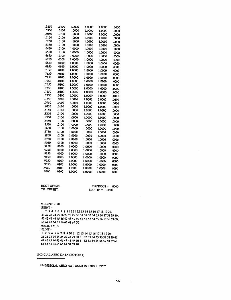
.5850 .0100 1.0000 1.0000 1.0000 .0000
.5950 .0100 1.0000 1.0000 1.0000 .0000
.6050 .0100 1.0000 1.0000 1.0000 .0000
.6150 .0100 1.0000 1.0000 1.0000 .0000
.6250 .0100 1.0000 1.0000 1.0000 .0000
.6350 .0100 1.0000 1.0000 1.0000 .0000
.6450 .0100 1.0000 1.0000 1.0000 .0000
.6550 .0100 1.0000 1.0000 1.0000 .0000
•6650 .0100 1.0000 1.0000 1.0000 .0000
•6750 .0100 1.0000 1.0000 1.0000 .0000
.6850 .0100 1.0000 1.0000 1.0000 .0000
•6950 .0100 1.0000 1.0000 1.0000 .0000
.7050 .0100 1.0000 1.0000 1.0000 .0000
.7150 .0100 1.0000 1.0000 1.0000 .0000
.7250 .01(30 1.0000 1.0000 1.0000 .0000
•7350 .0100 1.0000 1.0000 1.0000 .0000
•7450 .0100 1.0000 1.0000 1.0000 .0000
.7550 .0100 1.0000 1.0000 1.0000 .0000
•7650 .0100 1.0000 1.0000 1.0000 .0000
•7750 .0100 1.0000 1.0000 ! .0000 .0000
•7850 .0100 1.0000 1.0000 1.0000 ,0000
•7950 .0100 ! .0000 1.0000 1.0000 .0000
.8050 .0100 1.0000 1.0000 1.0000 .0000
.8150 .0100 I.{3000 1.0000 1.0000 .0000
.8250 .0100 1.0000 1.0000 1.0000 .0000
.8350 .0100 1.0000 1.0000 1.0000 .0000
.8450 .0100 1.0000 1.0000 1.0000 .0000
.8550 .0100 1.0000 1.0000 1.0000 .0000
.8650 .0100 ! .0000 1.0000 ! .0000 .0000
.8750 .0100 ! .0000 1.0000 1.0000 .0000
.8850 .0100 1.0000 1.0000 1.0000 .0000
•8950 .0100 1.0000 1.0000 1.0000 .0000
.9050 .0100 1.0000 1.0000 1.0000 .0000
.9150 .0100 1.0000 1.0000 1.0000 .0000
.9250 .0100 1.0000 1.0000 1.0000 ,0000
•9350 .0100 1.0000 1.0000 1.0000 .0000
•9450 .0100 1.0000 1.0000 1.0000 .0000
.9550 .0100 1.0000 1.0000 1.0000 .0000
.9650 .0100 1.0000 1.0000 1.0000 .0000
.9750 .0100 1.0000 1.0000 1.0000 .0000
.9900 .0200 1.0000 1.0000 1.0000 .0000
ROOT OFFSET DRPROOT = .0000
TIP OFFSET DRPTIP = .0000
MRGINT = 70
NGINT =
I 2 3 4 5 6 7 8 91011 12 13 14 15 16171g1920,
21 22 23 24 25 26 27 28 29 30 31 32 33 34 35 36 37 38 39 40,
41 42 43 44 45 46 47 48 49 50 51 52 53 54 55 56 57 58 59 60,
61 626364656667686970
MRLINT = 70
NLINT =
1 2 3 4 5 6 7 8 91011 121314151617151920,
21 22 23 24 25 26 27 28 29 30 31 32 33 34 35 36 37 38 39 40,
4l 42 43 44 45 46 47 48 49 50 51 52 53 54 55 56 57 58 59 60,
61 626364656667686970
INDICIAL AERO DATA (ROTOR 1)
***INDICIAL AFRO NOT USED IN THIS RUN***
56

AERODYNAMICS MODEL CHOICE OPBED -- 0
INBOARD TRAILED NW CORE SIZE (DEFAULT < 0.) HCOR -- -.0500
CURVED(1) OR STRAIGHT(2) NW (DEFAULT = 1) ICURV -- 1
LEAD TERMS ON/OFF (DEFAULT = 1 (ON)) ILEED = 1
AERODYNAMIC SWEEP DATA (ROTOR I)
RAINT SWEEP
.2962 .0000
.3050 .0000
.3150 .0000
.3250 .0000
.3350 .0000
.3450 .0000
.3550 .0000
.3650 .0000
.3750 .0000
.3850 .0000
.3950 .0000
.4050 .0000
.4150 .0000
.4250 .0000
.4350 .0000
.4450 .0000
.4550 .0000
.4650 .0000
.4750 .0000
.4850 .0000
.4950 .0000
.5050 .0000
.5150 .0000
.5250 .0000
.5350 .0000
.5450 .0000
.5550 .0000
.5650 .0000
.5750 .0000
.5850 .0000
.5950 .0000
.6050 .0000
.6150 .0000
.6250 .0000
.6350 .0000
.6450 .0000
.6550 .0000
.6650 .0000
.6750 .0000
.6850 .0000
.6950 .0000
.7050 .0000
.7150 .0000
.7250 .0000
.7350 .0000
.7450 .0000
.7550 .0000
.7650 .O000
.7750 .0000
.7850 .0000
.7950 .0000
.8050 .0000
.8150 .0000
.8250 .0000
.8350 .0000
RAE SWEEP
.2925 .0000
.3775 .0000
.4550 .0000
.5200 .0000
.5750 .0000
.6200 .0000
.6600 .0000
.7000 .0000
.7350 .0000
.7625 .0000
.7875 .0000
.8125 .0000
.8375 .0000
.8625 .0000
.8875 .0000
.9100 .0000
.9300 .0000
.9500 .0000
.9700 .0000
.9900 .0000
57

.8450 .0000
.8550 .0000
.8650 .0000
.8750 .0000
.8850 .0000
.8950 .0000
.9050 .0000
.9150 .0000
.9250 .0000
.9350 .0000
.9450 .0000
.9550 .0000
.9650 .0000
.9750 .0000
.99OO .0000
CFD DATA (ROTOR I)
***CFD INFO NOT USED IN THIS RUN***
CFD INFO USAGE OPCFD = 0
BVI INFO USAGE OPBVI = 0BLADE MOTION OUTPUT FILE OPMOTN = 0WAKE AGE CUTOFF FOR VORTEX SEGMENT CFD TEST PHICFD = 45.0000
CFD BOX BVI BOX
FORWARD .0000 UPSTREAM .0000OUTBOARD .0000 STARBOARD .0000T.E. .0000 DWNSTREAM .0000INBOARD .0000 PORT .0000
UPPER .0000 UPPER .0000LOWER .0000 LOWER .0000
WOPWOP/ROTONET INTERFACE
***WOPWOP/ROTONET INTERFACE NOT USED IN THIS RUN***
WOPWOP/ROTONET INTERFACE OUTPUT NOISFL = 0
BURST DATA (ROTOR 1)
***BURST MODEL NOT USED IN THIS RUN***
VORTEX BURST OPTION OPBURST = 0AZIMUTH TOLERANCE PSITOL = -1.0000VERTICAL DISTANCE TOLERANCE (Z/R) ZTOL = .0000CORE SIZE BURST FACTOR CORMULT = .0000
CIRCULATION BURST FACTOR CIRMULT = .0000
HHC DATA (ROTOR 1)
*** HHC NOT USED IN THIS CASE ***
VORTEX ROLLUP DATA (ROTOR 1)
*** ROLLUP MODEL USED IN TRIM AND HIRES ***
58

ROLLUP OPTION OPROLLU = 3
NUMBER OF TIP VORTEX CORES (MAX = ! 0) NTCORE = 9
NUMBER OF SECONDARY VORTEX CORES (MAX -- 10) NSCOR = 9
TIP CORE SIZES (RE. R) = .0100 .0167 .0233 .0300 .0450
SECONDARY CORE SIZES (RE. R) = .0100 .0167 .0233 .0300
WRITE ROLLUP INFO IN TRIM OPLOWR = 1
WRITE ROLLUP INFO IN HIRES OPHIWR = I
NUMBER OF ROLLUP CONVERGENCE ITERATIONS ITERRUP -- 2
NUMBER OF WAKE-TRIM ITERATIONS WITH ROLLUP ITERFRU = 2
TIP CORE SIZE FOR "LARGE CORE" CALCULATION CORELG = .3000R
NUMBER OF LARGE CORE CIRCULATION ITERATIONS ITERLGC = 20
LAG FACTOR FOR LARGE CORE ITERATIONS FLGCORG = .1000
PHASE-IN MODEL (0 POLYNOMIAL, I SPREITERJSACKS)
POLYNOMIAL:
NUMBER OF COEFFS FOR "PHASE-IN" FUNCTION
PHASE-IN WILL BE LINEAR.
VALUES FOR PHASE-IN FUNCTION
TIPFC0 .0000
TIPFC(l) .1592
TIPFC(2) .0000
TIPFC(3) .0000
TIFFC(4) .0000
TIPFC(5) .0000
TIPFC(6) .0000
TIPFC(7) .0000
TIPFC(8) .0000
TIPFC(9) .0000
TIPFC(10) .0000
PHASE-IN OF SECONDARY VORTEX (ON/OFF)SPREITER/SACKS:
CONSTANT IN SPREITER/SACKS ROLLUP MODEL (XY)
CONSTANT IN SPREITER/SACKS ROLLUP MODEL (Z)
OPROLSS = 0
NTIPFCT = 1
ISECPH = 0
CROLSSXY= .1250
CROLSSZ = .1250
SPIN OPTION ISPIN = 1
AGE TO START SPIN CALCULATIONS AFTER TAUC0 = .0000
TIME CONSTANT FACTOR (TAUCI*TAU) TAUC1 = 1.0000
ROLLUP Z CORRECTION OPTION (ON/OFF) IRUZCOR = 0
NUMBER OF WAKES TO SEARCH IN ROLLUP Z CORRECTION NSEARCH = 6
ROLLUP Z CORRECTION MODEL IRUDZ = 0
MULTI.CORE MODEL (0 (DEFAULT), 1, OR 2) ICORYCB = 2
EXPONENT IN CORE SIZE MODEL (DEFAULT = 1) COREXP = 2LARGE CORE CIRCULATION USAGE IN FREE WAKE IFWLGC = 1
.0750 .I000 .1500 .2000
.0450 .0750 .I000 .I500 .2000
MEASURED MOTION DATA (ROTOR 1)
*** MEASURED MOTION IS NOT BEING USED ***
MEASURED AERO DATA (ROTOR I)
*** MEASURED AERO IS NOT BEING USED ***
NONUNIFORM INFLOW MODEL
EXTENT OF NEAR WAKE, KNW = 9
EXTENT OF ROLLING UP WAKE, KRW = 9
EXTENT OF FAR WAKE, KFW = 108
EXTENT OF DISTANT WAKE, KDW = 108
ROLLUP INITIAL RADIAL STATION, RRU = 1.0000
ROLLUP INITIAL TIP VORTEX FRACTION, FRU = .0000
ROLLUP EXTENT (DEG), PRU = .00
NEAR WAKE TIP VORTEX FRACTION, FNW = .0000
59
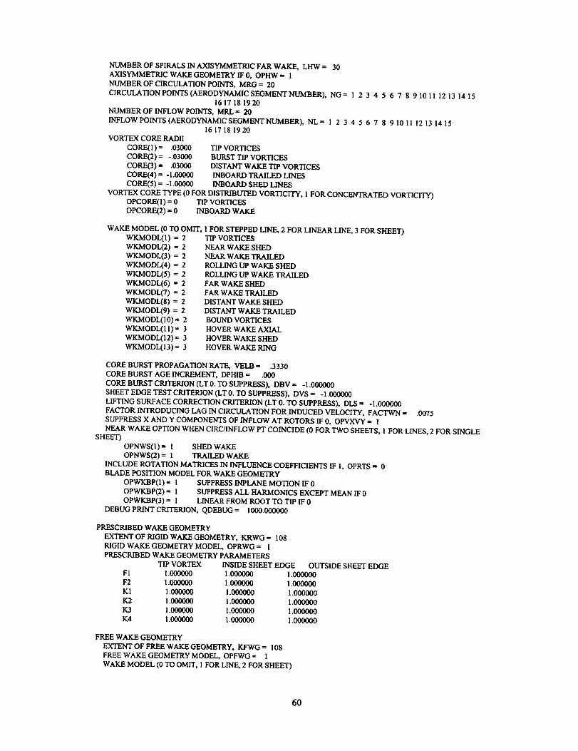
NUMBER OF SPIRALS IN AXISYMMETRIC FAR WAKE, LHW = 30
AXISYMMETRIC WAKE GEOMETRY IF 0, OPHW = i
NUMBER OF CIRCULATION POINTS, MRG = 20
CIRCULATION POINTS (AERODYNAM1C SEGMENT NUMBER), NG= 1 2 3 4 5 6 7 $ 9 10 11 12 13 14 1516 17 18 1920
NUMBER OF INFLOW POINTS, MRL = 20
INFLOW POINTS(AERODYNAMIC SEOMENTNUMBER), NL-- 1 2 3 4 5 6 7 8 9 10 11 12 13 14 1516 17 18 1920
VORTEX CORE RADII
CORE(1)= .O3O0O
CORE(2)= -.03000CORE(3) = .03000
CORE(4) = -I.00000
coRE(5)= -i.ooooo
TIP VORTICES
BURST TIP VORTICES
DISTANT WAKE TIP VORTICES
INBOARD TRAILED LINES
INBOARD SHED LINES
VORTEX CORE TYPE (0 FOR DISTRIBUTED VORTICITY, 1 FOR CONCENTRATED VORTICITY)
OPCORE(I) = 0 TIP VORTICES
OPCORE(2) = 0 INBOARD WAKE
WAKE MODEL (0 TO OMIT,
WKMODL(1) = 2
WKMODL(2) = 2
WKMODL(3) = 2
WKMODL(4) = 2
WKMODL(5) = 2
WKMODL(6) = 2
WKMODL(7) = 2
WKMODL(8) = 2
WKMODL(9) = 2
WKMODL(10) = 2
WKMODL(I l) --- 3
WKMODL(12) = 3
WKMODL(13) = 3
! FOR STEPPED LINE, 2 FOR LINEAR LINE, 3 FOR SHEET)TIP VORTICES
NEAR WAKE SHED
NEAR WAKE TRAILED
ROLLING UP WAKE SHED
ROLLING UP WAKE TRAILED
FAR WAKE SHED
FAR WAKE TRAILED
DISTANT WAKE SHED
DISTANT WAKE TRAILED
BOUND VORTICES
HOVER WAKE AXIAL
HOVER WAKE SHED
HOVER WAKE RING
CORE BURST PROPAGATION RATE, VELB = .3330
CORE BURST AGE INCREMENT, DPHIB = .000
CORE BURST CRITERION (LT 0. TO SUPPRESS), DBV = -I .000000
SHEET EDGE TEST CRITERION (LT 0. TO SUPPRESS), DVS = -I.000000
LIFTING SURFACE CORRECTION CRITERION (LT 0. TO SUPPRESS), DIS = -I.000000
FACTOR INTRODUCING LAG IN CIRCULATION FOR INDUCED VELOCITY, FACTWN = .0075
SUPPRESS X AND Y COMPONENTS OF INFLOW AT ROTORS IF 0, OPVXVY = I
NEAR WAKE OPTION WHEN CIRC/rNFLOW PT COINCIDE (0 FOR TWO SHEETS, l FOR LINES, 2 FOR SINGLE
SHEET)
OPNWS(I) = 1 SHED WAKE
OPNWS(2) = I TRAILED WAKE
INCLUDE ROTATION MATRICES IN INFLUENCE COEFFICIENTS IF !, OPRTS = 0
BLADE POSITION MODEL FOR WAKE GEOMETRY
OPWKBP(1) = 1 SUPPRESS INPLANE MOTION IF 0
OPWKBP(2) = I SUPPRESS ALL HARMONICS EXCEPT MEAN IF 0
OPWKBP(3) = 1 LINEAR FROM ROOT TO TIP IF 0
DEBUG PRINT CRITERION, QDEBUG = I000.000000
PRESCRIBED WAKE GEOMETRY
EXTENT OF RIGID WAKE GEOMETRY, KRWG = 108
RIGID WAKE GEOMETRY MODEL, OPRWG = 1
PRESCRIBED WAKE GEOMETRY PARAMETERS
TIP VORTEX INSIDE SHEET EDGE
F1 1.000000 1.000000
F2 1.000000 1.000000
Ki 1.000000 ! .000000
K2 1.000000 1.000000
K3 1.000000 1.000000
K4 i .000000 1.000000
OUTSIDE SHEET EDGE
1.000000
1.000000
1.000000
1.000000
1.000000
1.000000
FREE WAKE GEOMETRY
EXTENT OF FREE WAKE GEOMETRY, KFWG = 108
FREE WAKE GEOMETRY MODEL, OPFWG = 1
WAKE MODEL (0 TO OMIT, I FOR LINE, 2 FOR SHEET)
6O

WGMODL(I) = 1 INBOARD TRAILED WAKE
WGMODL(2) --- ! SHED WAKEVORTEX CORE RADII
COREWG(1) = .09000 TIP VORTICES
COREWG(2) = -.03000 BURST TIP VORTICES
COREWG(3) = 1.00000 INBOARD TRAILED LINES
COREWG(4) = -I.00000 INBOARD SHED LINES
RADIAL STATIONS FOR TRAILED VORTICITY
RTWG(1) = .I000 INSIDE SHEET EDGE
RTWG(2) = .4000 OUTSIDE SHEET EDGE OR TRAILED LINE
NUMBER OF REVOLUTIONS OF WAKE BELOW POINT CALCULATING VELOCITY, MRVBWG = 2
GENERAL UPDATE, LDMWG= 18
BOUNDARY UPDATE, NDMWG= 9 9 9 9 9 4 4 4 4 4 4 4 4 4 9 9 9 9
999994444444449999
WAKE VELOCITY CRITERIA
DQWG(1) = .000500 NEAR WAKE ELEMENTS
DQWG(2) = .000500 BOUND VORTEX
NUMBER OF WAKE GEOMETRY ITERATIONS, ITERWG = 8
FACTOR INTRODUCING LAG IN DISTORTION, FACTWG -- .50000
DEBUG PRINT CRITERIA
IPWGDB(I) = 6 PRINT BEFORE GENERAL UPDATE
IPWGDB(2) = 6 PRINT AFTER EACH ITERATION
QWGDB = .100000 PRINT VELOCITY CONTRIBUTION
1AIRFRAME DATA
TITLE =
CONFIGURATION (0 FOR ONE ROTOR, 1 FOR SINGLE MR/TR, 2 FOR TANDEM, 3 FOR TILTROTOR), CONFIG = 0
GROSS WEIGHT (LB OR KG) = .0000
AIRCRAFT MOMENTS OF INERTIA
IXX = .0000 IXY = .0000
IYY = .0000 IXZ = .0000
IZZ = .0000 IYZ = .0000
TRANSMISSION GEAR RATIO (OMEGA2/OMEGAI), TRATIO = 1.0000
SHAFT ANGLE OF ATTACK (DEG), ASHAFT = .00 .00
SHAFT CANT ANGLE (DEG), ACANT = .00 .00
ROTOR-2 AZIMUTH ANGLE (DEG) WHEN ROTOR-1 AZIMUTH ANGLE IS ZERO, DPSI21 = .00
HORIZONTAL TAIL CANT ANGLE (DEG), CANTHT = .00
VERTICAL TAIL CANT ANGLE (DEG), CANTVT = .00
LOCATION OF AIRCRAFT COMPONENTS - FUSELAGE STATION
CENTER OF GRAVITY .0000 .0000 .0000
ROTOR-I HUB .0000 .0000 .0000
ROTOR-2 HUB .0000 .0000 .0000
WING-BODY .0000 .0000 .0000
HORIZONTAL TAIL .0000 .0000 .0000
VERTICAL TAIL .0000 .0000 .0000
POINT OFF ROTOR .0000 .0000 .0000
BUTTLINE WATERLINE
CONTROL SYSTEM - GAIN PHASE
COLLECTIVE 1.000000
LATERAL CYCLIC 1.000000 .000
LONGITUDINAL CYCLIC 1.000000 .000
PEDAL .000000
FLAPERON .000000
THROTTLE .000000
AILERON .000000
ELEVATOR .000000
RUDDER .000000
CONTROL INPUTS WITH STICKS CENTERED, CNTRLZ = .00
.00 .00 .00 .00 .00
.00 .00 .00 .00 .00
AIRCRAFT AERODYNAMIC CHARACTERISTICS
WING-BODY INCIDENCE ANGLE (DEG), IWB = .00
WING-BODY MAXIMUM ANGLE OF ATTACK (DEG), AMAXW =
WING-BODY INDUCED DRAG (L**2/DI), DRGIW = .0000
WING-BODY VERTICAL DRAG, DRGVW = .0000
.00
61

BASEANGLE-OF-ATTACK FLAP FLAPERON
WING-BODY LIFT .000 .000 .000
WING-BODY DRAG .000 .000 .000
WING-BODY MOMENT .000 .000 .000 .000
SIDESLIP ROLLING YAWING AILERON
WING-BODY SIDE .000 .000 .000
WING-BODY ROLL .000 .000 .000 .000
WING-BODY YAW .000 .000 .000 .000
ANGLE-OF-ATTACK CONTROL INCIDENCE ALPHA-MAX
HORIZONTAL TAIL LIFT .000 .000 .00 .00
VERTICAL TAIL LIFT .000 .000 .00 .00
SUPPRESS AIRFRAME/TAIL INTERFERENCE IF 0, OPTINT = 0
AREA FOR WING/TAIL INTERFERENCE, FETAIL = .000
HORIZONTAL TAIL LENGTH FOR INTERFERENCE, LHTAIL =
VERTICAL TAIL HEIGHT FOR INTERFERENCE, HVTAIL =
.000
.000
DRIVE TRAIN MODEL
CONFIGURATION (0 FOR ONE RTR, 1 FOR ENG BY RTR-1, 2 FOR ENG BY RTR-2, 3 FOR SYM), ENGPOS = 0
ENGINE POWER/THROTrLE DERIVATIVE, THRTLC s .000
ENGINE DAMPING FACTOR, KEDAMP = .0000
ENGINE ROTARY INERTIA, IENO = .000
ROTOR-! SHAFT SPRING CONSTANT, KMAST1 -- .00000E+00
ROTOR-2 SHAFT SPRING CONSTANT, KMAST'2 = .00000E+00
INTERCONNECT SHAFT SPRING CONSTANT, KICS = .00000E+00
ENGINE SHAFT SPRING CONSTANT, KENG -- .00000E+O0
ENGINE SHAFT STRUCTURAL DAMPING, GSE = .00000
INTERCONNECT SHAFT STRUCTURAL DAMPING, GSI = .00000
GOVERNOR PARAMETERS - ENGINE ROTOR-1 ROTOR-2
PROPORTIONAL GAIN .000000 .000000 .000000
INTEGRAL GAIN .000000 .000000 .000000
TIME LAG I .000000 .000000 .000000
TIME LAG 2 .000000 .000000 .000000
IMAIN ROTOR BLADE MODES OMEGA = 112.470 RAD/SEC, = 17.900 HZ, -- 1074.01 RPM
BENDING MODES, HINGED BLADE (T75 = 4.92)
FREQUENCY (PER REV) = .483 !.074 2.953 5.128 5.554 10.325 11.915 18.292 23.646 27.852
39.019 46.009 48.438 56.320 69.788 73.169 97.474 126.348 195.644 246.331
FREQUENCY(HZ) = 8.649 19.233 52.864 91.799 99.417 184.819 213.286 327.434 423.259 498.548
698.441 823.561 867.049 1008.146 1249.210 1309.745 1744.797 2261.653 3502.056,4409.366
MODE NUMBER 1 R = .0 .1 .2 .3 .4 .5 .6 .7 .8 .9 1.0
DEFLECTION FLAP .000 .000 .000 .000 .001 .002 .004 .005 .007 .008 .009
LEAD .000 -.018 -.119 -.223 -.330 -,439 -.549 -,661 -.773 -,886 -1,000
SLOPE FLAP .000 .000 -.002 .004 .014 .015 .015 .013 .012 .011 .011
LEAD .000 -1.006 -1.029 -1.057 -1.079 -1.096 -I.Iil -1.120 -1.128 -1.134 -1.136
CURVATURE FLAP .000 -.008 .002 .107 .057 -.005 -.010 -.018 -.010 -.008 ,000
LEAD .000 -.080 -.303 -.253 -.182 -.167 -.117 -.084 -.063 -.059 .000
MODE NUMBER 2 R = .0 .1 .2 .3 .4 .5 .6 .7 .8 .9 1.0
DEFLECTION FLAP .000 .017 .117 .219 .325 .434 .545 .658 .771 .885 1.000
LEAD .000 .000 .001 .003 .004 .004 .005 .005 .006 .006 .007
SLOPE FLAP .000 .997 1.003 1.035 1.080 1.103 1.120 1.129 1.138 1.144 1.148
LEAD .000 .012 .013 .011 .007 .006 .005 .006 .006 .006 .006
CURVATURE FLAP .000 .009 .147 .475 .337 .188 .120 .097 .063 .065 .000
LEAD .000 ,008 .010 -.046 -.029 -.004 -,001 .000 .002 .002 .000
62

MODE NUMBER 3 R = .0 .I .2 .3 .4 .5 .6 .7 .8 .9 1.0
DEFLECTION FLAP .000 -.057 -.379 -.658 -.806 -.803 -.664 -.399 -.018 .462 .992
LEAD .000 .008 .054 .092 .II0 .106 .084 .047 -.002 -.060 -.123
SLOPE FLAP .000 -3.241 -3.143 -2.265 -.676 .715 2.042 3.239 4.363 5.157 5.357
LEAD .000 .457 .444 .300 .058 -.134 -.301 -,432 -.542 -.613 -.630
CURVATURE FLAP .000 -.014 3.417 14.205 15.350 13.326 12.731 11.603 10.274 5.059 .000
LEAD .000 .021 -.571 -2.252 -2.234 -1.750 -1.511 -1.182 -.963 -.427 .000
MODE NUMBER 4 R = .0 .I .2 .3 .4 .5 .6 .7 .8 .9 1.0
DEFLECTION FLAP .000 -.008 -.054 -.069 .016 .162 .285 .316 .204 -.070 -.435
LEAD .000 .059 .380 .610 .717 .705 .570 .326 .000 -.422 -.901
SLOPE FLAP .000 -.456 -.426 .289 1.315 1.466 .874 -.342 -1.949 -3.392 -3.736
LEAD .000 3.378 2.890 1.666 .485 -.741 -1.937 -2.867 -3.714 -4.638 -4.842
CURVATURE FLAP .000 -.226 2.401 11.354 6.418 -2.502 -9.476-14.256-17.289 -9.197 .000
LEAD .000 -.925 -9.670-12.627-II.803-12.297 -11.307 -7.435 -10.365 -5.815 .000
MODENUMBER 5 R = .0 .1 .2 .3 .4 .5 .6 .7 .8 .9 1.0
DEFLECTION FLAP .000 .051 .334 .478 .268 -.180 -.614 -.819 -.628 .023 .929
LEAD .000 .011 .065 .!12 .175 .234 .248 .195 .072 -.128 -.369
SLOPE FLAP .000 2.925 2.545 -.161 -3.758 -4.776 -3.543 -.283 4.270 8.356 9.320
LEAD .000 .599 .477 .517 .694 .413 -.170 -.874 -1.621 -2.303 -2.446
CURVATURE FLAP .000 -.076-12.110-39.606-24.497 1.692 23.582 39.818 49.174 25.867 .000
LEAD .000 -.403 -1.360 2.336 -.323 -4.625 -6.911 -6.876 -8.209 -4.089 .000
MODENUMBER 6 R= .0 .! .2 .3 .4 .5 .6 .7 .8 .9 1.0
DEFLECTION FLAP .000 -.041 -.258 -.119 .635 1.194 .873 -.123 -.860 -.402 .994
LEAD .000 .017 .101 .086 -.063 -.201 -.224 -.141 -.037 .043 .107
SLOPE FLAP .000 -2.357 -I.402 4.950 8.420 1.530 -7.589-10.659 -2.256 10.922 15.143
LEAD .000 .985 .538 -.944 -1.727 -.867 .401 1.085 .924 .698 .616
CURVATURE FLAP .000 -.888 33.883 75.490-22.653-96.191-74.016 24.705 131.576 102.299 .000
LEAD .000 -.675-10.091-15.729 1.945 12.459 11.452 i.444 -2.738 -1.761 .000
MODE NUMBER 7 R = .0 .1 .2 .3 .4 .5 .6 .7 .8 .9 1.0
DEFLECTION FLAP .000 -.015 -.083 -.058 .089 .222 .214 .070 -.068 -.065 .051
LEAD .000 -.063 -.331 -.312 -.055 .294 .618 .759 .618 -.018 -.999
SLOPE FLAP .000 -.852 -.362 .944 1.714 .728 -.893 -1.716 -.784 .781 1.306
LEAD .000-3.562-I.383 1.643 3.212 3.628 2.512 .253-3.600-8.802-10.170
CURVATURE FLAP .000 1.134 9.290 14.329-1.711-15.315-14.983 .769 15.515 12.459 .000
LEAD .000 6.819 31.388 24.876 7.939 -.770 -20.681 -24.787 -54.446 -36.179 .000
MODE NUMBER 8 R = .0 .1 .2 .3 .4 .5 .6 .7 .8 .9 1.0
DEFLECTION FLAP .000 .034 .187-.351-1.276-.633 .942 1.080-.396-.783 1.000
LEAD .000 -.009 -.044 .058 .234 .175 -.042 -.125 -.042 .029 .015
SLOPE FLAP .000 1.973 -.283-10.375 -3.639 15.104 11.640 -9.363-14.726 9.463 21.252
LEAD .000 -.502 .063 1.925 .897 -1.893 -1.853 .218 1.085 .195 -.283
CURVATURE FLAP .000 2.548-75.753 -64.552 189.828 110.590-166.336-192.544 123.069 262.096 .000
LEAD .000 .083 15.460 11.049-28.647-17.541 16.128 18.860 -2.460-10.525 .000
MODENUMBER 9 R= .0 .1 .2 .3 .4 .5 .6 .7 .8 .9 1.0
DEFLECTION FLAP .000 .011 .033 -.055 -.189 -.170 .004 .104 .048 -.021 -.014
LEAD .000 .058 .181 -.235 -.783 -1.014 -.649 .127 .806 .424 -l.000
SLOPE FLAP .000 .599 -.303 -1.375 -.888 1.284 1.726 .124 -.953 -.243 .19l
LEAD .000 3.215-1.587-5.793-4.496 .497 6.355 8.490 3.093-10.753-15.587
63

CURVATURE FLAP .000 -2.983-12.341 -6.332 17.486 18.050 -9.108-18,141 -.439 9.557 .000
LEAD .000 -15.540 -63,812 -I1.018 31.336 65.874 40.965 -1.464-I16.728-I16.958 .000
MODE NUMBER 10 R = .0 .1 .2 .3 .4 .5 .6 .7 .8 .9 1.0
DEFLECTION FLAP .000 -.028 -.084 .585 .890 -.581 -.733 .732 .346 -.933 .999
LEAD .000 .004 .015 -.096 -.149 .060 .115 -.037 -.041 .047 -.045
SLOPE FLAP .000 -1.581 1.970 9.712 -7.877-13.968 11.262 10.720-17.497 2.954 26.641
LEAD .000 .235 -.303-1.597 1.114 2,066-I.020-1.255 1.065 .005-1.330
CURVATURE FLAP .000 2.283 88.389 -17.612-247.881 175.593 200.410-225.084-154.585 450.269 .000
LEAD .000 .295-15.511 4.029 35.489-21.128-25.038 19.554 12.776-25.622 .000
TORSION MODES
FREQUENCY (PER REV) = 16.061 7.964 28.720 41.858 60.353
74.197 84.180 95.445 I15.080 136.633 156.186
FREQUENCY (HZ) = 287.501 142.548 514.091 749.258 1080.324
1328.136 1506.843 1708.484 2059.944 2445.752 2795.762
MODE NUMBER 1
DEFLECTION
SLOPE
R = .0 .! .2 .3 .4 .5 .6 .7 .8 .9 1.0
.000 .000 1.000 1.000 1.000 1.000 1.000 1.000 1.000 1.000 1.000
.000 .000 .000 .000 .000 .000 .000 .000 .000 .000 .000
MODE NUMBER 2
DEFLECTION
SLOPE
R = .0 .1 .2 .3 .4 .5 .6 .7 .8 .9 1.0
.000 .000 .009 .077 .263 .449 .623 .778 .908 .973 !.000
.000 .000 .208 1.377 1.998 1.787 1.635 1.507 .959 .458 .000
MODE NUMBER 3
DEFLECTION
SLOPE
R= .0 .1 .2 .3 .4 .5 .6 .7 .8 .9 1.0
.000 .000 -.043 -.321 -.950 -1.239 -1.124 -.666 .011 .672 1.000
.000 ,000 -.870-5.504-5.222 -.847 3.168 5.807 7.232 5.633 .000
MODE NUMBER 4
DEFLECTION
SLOPE
R = .0 .1 .2 .3 .4 .5 .6 .7 .8 .9 1.0
.000 .000 .049 .318 .782 .639 .074-.558-.655 .361 1.000
•000 .000 .972 4.959 2.197 -4.281 -6.501 -5.349 5.297 11.473 .000
MODE NUMBER 5
DEFLECTION
SLOPE
R = .0 .1 .2 .3 .4 .5 .6 .7 .8 .9 1.0
.000 .000 -.366 -I.283 -2.014 .525 2.302 1.290 -.983 -.254 1.000
•000 .000 -4.688-16.580 12.507 26.837 6.964-25.908 -9.387 18.173 .000
RIGID PITCH FREQUENCY(PERREV) - COLLECTIVE= 16.061, CYCLIC = 14.039, REACTIONLESS =
26.432
RIGID PITCH FREQUENCY (HZ) - COLLECTIVE= 287.501, CYCLIC = 251.306, REACTIONLESS =
473.135
NUMBER OF BENDING MODES = I 0 NUMBER OF COLLOCATION FUNCTIONS = 20
NUMBER OF TORSION MODES = 5 NUMBER OF COLLOCATION FUNCTIONS -- 10
FLAP HINGE OFFSET 1 .0825 LAG HINGE OFFSET = .0825
FLAP HINGE SPRING -- .00 LAG HINGE SPRING = 2805.00
HINGE PITCH ANGLE = .00 + 1.0000 * T75 '= 4.92
HINGE SLOPE, FLAP = -.0001 .9972 -3.2406 -.4535 2.9252 -2.3480 -.8620 1.9483 .6255 -1.5988
HINGE SLOPE, LEAD=-l.0049 .0115 .4572 3.3858 .6025 .9908-3.6216 -.5020 3.3516 .2320STRUCTURAL COUPLING = 1.0000
PITCH/BENDING KINEMATIC COUPLING, KP -- .0000 .0000 .0000 .0000 .0000 .0000 .0000 .0000 .0000 .0000
COLLECTIVE, CYCLIC, REACTIONLESS PITCH STIFFNESS = 18462.00 14106.00 50000.00
MB = 10.4704 *IB/R**2 = 1.037 SB = 2.2313 *IB/R= 1.340 I0 = !.0126 *IB = 3.687
IP = .001554 *IB = .0057
REFERENCE - IB = 3.641 RADIUS = 6.063
PRECONE = .00 DROOP = .00 SWEEP -- .00
PITCH AXIS DROOP = .00 PITCH AXIS SWEEP -- .00
10"*'0"'0"**'0
AIRCRAFT TRIM
64

NONUNIFORM INFLOW WITH FREE WAKE GEOMETRY
WAKE/TRIM ITERATION NUMBER 3 (MAXIMUM = 3)
NUMBER OF TRIM ITERATION = 1 (MAXIMUM = 80, TOLERANCE = .00050)
WIND TUNNEL, TRIM OPTION NUMBER 15
FORCES
TRIMMED TARGET ERROR
** CTIS
CP/S
CL/S
CX/S
CY/S
** BETAC
** BETAS
.0769408 .0769300 .0001403 **
.0027057 .0000000 .0000000
.0765351 .0000000 .0000000
.0080267 .0000000 .0000000
-.0006563 .0000000 .0000000
.0133 .0000 .0002325 **
-.0048 .0000 .0000841 **
CONTROL
TRIMMED INPUT
**DEL0 = 5.25 COLL ffi 6.29"*
**DELC = -1.04 LATCYC= -2.84"*
**DELS = .37 LNGCYC= 3.25"*
THETA-T= 5.01 APITCH= 5.01
PSI-T = .00 AYAW = .00
COLLECTIVE CONTROLS - DEL0 ffi 5.25 TGOVRI= .00 • TGOVR2= .00
THROTTLE CONTROLS -DELT= .00 C-T = .00
AIRCRAFT CONTROLS -DELF= .00 DELE = .00 DELA = .00 DELR= .00
ROTOR CONTROLS -T75 = 5.25 TIC = 1.04 T1S = -.37
PERFORMANCE
VEL = .1494= 101.87 DPH1-F = .0000= .00 THETA-FT= .00 T75-Ri = 5.25
Q = .01116= 12.67 DTHETA-F = .0000= .00 PHI-FT = .00 T1C-RI= 1.04
DPSI-F = .0000= .00 TIS-R1 = -.37
THETA-FP= .00 T75-R2= .00
VELX ffi .1494= 101.87 DX-F = .0000= .00 PSI-FP = .00 TIC-R2= .00
VELY = .0000= .00 DY-F = .0000= .00 TIS-R2= .00
VELZ = .0000= .00 DZ-F = .0000= .00 THETA-T = 5.01 DELF = .00
PSI-T = .00 DELE = .00
VCLIMB= .0000 = .00 DDZ-F = .0000 = .00 DELA = .00
VSIDE = .0000 = .00 DELR = .00
CW/S = .0000 = .0 DOMEGA = .(3000 = .00 DELT = .00
CONVERGENCE
CIRCULATION ITERATIONS = 3
ROTORol CG/S-RMS = .0000379
BLADE MOTION ITERATIONS = 1
ROTOR-I
(MAXIMUM = 70, TOLERANCE = .00010)
G/E = .3795
(MAXIMUM = 50, TOLERANCE = .00800)
BETA-RMS = .0002 .0016 .0001 .0000 .0000 .0000 .0000 .0000 .0000 .0000
THETA-RMS = .0000 .0002 .0000 .000(3 .0000
BETA/E = .0309 .1938 .0078 .0009 .0014 .0005 .0001 .0001 .0000 .0000
THETA/E ffi .0009 .0225 .0006 .0002 .0000
AIRFRAME PERFORMANCE
AERODYNAMIC LOADS
WB-LIFT = .00 WB-SIDE=
WB-DRAG = .00 WB-ROLL =
WB-PITCH = .00 WB-YAW =
.00 HT-LIFT = .00 VT-LIFT = .00
.00 I-IT-DRAG = .00 VT-DRAG =
.00
.00
WING-BODY
ALPHA = .00 DELF = .00 LIFT/Q = .000 SIDEFORCE/Q= .000
BETA = .00 DELA = .00 DRAG/Q = .000 ROLLMOM/Q = .000
DALPHA = .000 AFLAP= .00 PITCHMOM/Q= .000 YAWMOM/Q = .000
65

Q-WB = 12.67 LX-R1 = .0000 LX-R2 = .0000 VELX-WB = .149
Q-RATIO= 1.0000 LY-R1 = .00(_ LY-R2 = .0000 VELY-WB = .000LZ-RI = .0000 LZ-R2 = .0000 VELZ-WB = .000
HORIZONTAL TAIL
ALPHA = .00 DELE = ,0000 LIFT/Q = .000 DRAG/Q = .000
Q-HT = 12.67 LX-RI = .0000 LX-R2 = .00(30 VELX-HT = .149
Q-RATIO= !.0000 LY-RI = .0000 LY-R2 = .0000 VELY-HT = .000EP-TAIL= .000 LZ-R1 = .0000 LZ-R2 = .0000 VELZ-HT = .000
VERTICAL TAIL
ALPHA = .00 DELR = .0000 LIFT/Q = .000 DRAG/Q = .000
Q-VT = 12.67 LX-R1 = .0000 LX-R2 = .0000 VELX-VT = .149
Q-RATIO= 1.0000 LY-R1 = .0000 LY-R2 = .0000 VELY-VT _ .000
SIG-TAIL= .000 LZ-R1 = .0000 LZ-R2 = .0000 VELZ-VT = .000
GUST VELOCITIES
ROTORol HUB
ROTOR-2 HUB
WING-BODY
HORIZONTAL TAIL
VERTICAL TAIL
UG= .0000 VG= .0000 WG= .0000
UG= ,0000 VG= .0000 WG= .0000
UG= .0000 VG= .0000 WG= .0000
UG= .0000 VG-- .0000 WG= .0000
UG= .0000 VG= .0000 WG= .0000
MAIN ROTOR PERFORMANCE
MUX= .1488 MUX-TPP= .1488 ALF-HP = -5.01 MTIP = .6190 T75= 5.25 T1S = -.37 T1C = 1.04
MUY= .0000 MUY-TPP= .0000 ALF-TPP= -4.99 MAT = .7111 B0 = 1.03 B1C-HP= .01 BIS-HP= .00
MUZ = -.0130 MUZ-TPP=-.0130 ALF-CP = -4.64 P-lIP= .00 BIC--CP= -.35 BIS-CP=-1.05
L = .0202 L-INT = .0000
TE-FLAP INPUT DEFLECTION ANGLES (OPFLAP=3)
PSI FLAP ANGLE,DEG
10.0 .00
20.0 .00
30.0 -.44
40.0 -2.62
50.0 -6.25
60.0 -9.88
70.0 -12.06
80.0 -12.50
90.0 -12.50
100.0 -12.50
II0.0 -12.50
120.0 -12.50
130.0 -12.06
140.0 -9.88
150.0 -6.25
160.0 -2.62
170.0 -.44
180.0 .00
190.0 .00
200.0 .00
210.0 .00
220.0 .00
230,0 .00
240.0 .00
250.0 .00
260.0 .00
270.0 .00
280.0 .00
290.0 .00
300.0 .00
66

310.0 .00
320.0 .00
330.0 .00
340.0 .00
350.0 .00
360.0 .00
BENDING MODES, HINGED BLADE (T75 = 4.92)
FREQUENCIES (PER REV) = .4832 1.0744 2.9533 5.1284 5.5540 10.3250 11.9153 18.2923 23.6455 27.8516
FLAP TIP DE.FLECTION = .0088 1.0000 .9925 -.4347 .9295 .9942 .0506 .9999 -.0144 .9990
LAG TIP DEFLECTION = 1.0000 -.0070 .1226 .9006 .3689 -.1074 .9987 -.0146 .9999 .0449
TORSION MODES
FREQUENCIES (PER REV) = 16.0614 7.9635 28.7199 41.8576 60.3528
COLLECTIVE, CYCLIC, REACTIONLESS PITCH FREQUENCIES (PER REV) = 16.0614 14.0393 26.4319
BLADE BENDING HARMONICS (DEG)
N=0
N=I
N= 2
N=3
N= 4
N=5
N=6
N=7
N=8
N= 9
N=I0
N=I 1
N=I2
N=13
BETA(1) BETA(2) BETA(3) BETA(4) BETA(5)
COS SIN COS SIN COS SIN COS SIN COS SIN
.2921 .0000 I.I104 .0000 -.0603 .0000 -.0071 .0000 -.028g .0000
-.0322 -.0416 .0123 .0477 .0002 -.0491 -.0006 .0036 .0003 -.0059
•0015 .0017 -.0852 .0062 .0122 .0106 .0006 -.0007 -.0023 .000g
-.0004 -.0003 -.0115 -.0073 -.0460 -.0112 .0008 -.0008 -.0004 -.0018
-.0003 -.0005 -.0052 -.0041 -.0068 -.0022 -.0011 -.0001 .0024 -.0019
.0000 .0000 .0007 -.0020 .0007 -.0017 .0012 -.0002 -.0004 .0025
•0001 -.0001 -.0007 .0008 .0005 .0005 -.0012 .0004 .0057 -.0037
.0001 .0000 -.0003 .0004 .0002 .0001 -.0003 .0001 .0014 -.0004
.0000 .0000 .0003 .0004 .0001 .0001 .0000 .0000 .0002 .0001
.0000 .0000 .0001 .0000 -.0001 -.0001 .0000 .0000 -.0001 .0000
•0000 .0000 .0002 -.0004 .0000 .0000 .0000 -.0001 -.0001 .0003
•0000 .0000 .0001 -.0002 .0000 .0001 .0000 -.0001 -.0001 .0002
.0000 .0000 -.0001 .0000 .0000 .0000 .0000 .0000 .0000 .0000
.0000 .0000 -.0001 .0001 -.0001 .0000 .0000 .0000 .0000 -.0001
N=0
N=I
N=2
N= 3
N=4
N=5
N= 6
N= 7
N=8
N=9
N=10
N=I 1
N=12
N=I3
BETA(6) BETA(7) BETA(8) BETA(9) BETA(10)cos sIN cos sIN cos sIN cos sIN cos sIN
.0042 .0000 -.0083 .0000 .0002 .0000 -.0020 .0000 .0001 .0000
.0003 .0029 .0000 .0005 .0001 .0005 .0000 .0000 .0001 .0003
-.0012 -.0003 -.0001 -.0001 -.0004 .00(30 .0000 .0000 -.0002 -.0001
-.0001 -.0005 -.0001 .0001 -.0001 -.0001 .0000 .0000 .0000 .0000
•0000 -.0005 -.0001 .0000 -.0001 -.0001 .0000 .0000 .0000 .0000
.0003 .0000 .0001 -.0001 .0001 -.0001 .0000 .0000 .0000 .0000
-.0002 .0004 .0000 .0001 .0000 .0000 .0000 .0000 .0000 .0000
-.0002 .0001 .0000 .0000 .0000 .0000 .0000 .0000 .0000 .0000
-.0001 .0003 .0000 .0000 .0001 .0001 .0000 .0000 .0000 .0000
-.0003 -.0002 -.0001 .0000 .0000 .0000 .0000 .0000 .0000 .0000
.0014 -.0003 .0000 -.0001 .0001 .0000 .0000 .0000 .0000 .0000
-.0005 -.0002 -.0002 .0002 .0000 .0000 .0000 .0000 .0000 .0000
.0002 .0001 .0001 .0000 .0000 .0000 .0000 .0000 .0000 .0000
.0001 .0002 .0001 .0001 .0000 -.0001 .0000 .0000 .0000 .0000
TIP DEFLECTION HARMONICS (DEG)
N=0
N = 1
N=2
N=3
N=4
N=5
N=6
N= 7
N= 8
N= 9
N=10
N-i I
GIMBAL/TEETER HARMONICS (DEG)
FLAP LAG BETAG BETAGC BETAGS
COS SIN COS SIN COS SIN COS SIN COS SIN
1.0334 .0000 .2491 .0000
.0133 -.0048 -.0327 -.0467
-.0773 .0173 .0034 .0026
-.0580 -.0203 -.0054 -.0029
-.0093 -.0085 -.0013 -.0015
.0008 -.0013 .0010 .0005
•0054 -.0018 .0012 -.0010
.0012 .0002 .0004 .0000
.0006 .0009 .0001 .0000
-.0003 -.0002 .0000 .0000
•0016 -.0004 -.0002 .0000
-.0005 -.0001 -.0001 .0002
67

N=I2 .0002 .0001 .0001 .0000
N=I3 .0000 .0002 .0001 .0001
BLADE PITCH/TORSION HARMONICS (DEG)
THETA(D) THETA(I ) THETA(2) THETA(3) THETA(4)
cOS SIN COS SIN COS SIN COS SIN COS SINN= 0 .0205 .0000 .4419 .0000 .0257 .0000 .0019 ,0000 .0013 .0000
N= l -.0072 .0414 -.0981 .5819 -.0042 .0251 -.0016 .0087 .0002 -.0005
N= 2 -.0063 -.0027 -.3216 -.1351 -.0155 -.0057 -.0052 -.0018 .0003 .0001
N= 3 .0018 -.0021 ,0936 -.1033 .0034 -.0050 .0013 -.0016 .0001 .0002
N = 4 -,0005 -.0002 -.0200 -.0083 -.0005 -.0005 ..0002 -.0003 .0001 .0000
N= 5 .0018 -.0012 .0843 -.0559 .0024 -.0021 .0009 -.0006 -.0001 .0001
N= 6 .0008 .0019 .0392 .0824 .0010 .0018 -.0003 .0009 -,0001 .00130
N= 7 -.0006 -.0004 -.0251 -.0173 -.0005 -.0001 -.0003 .0000 .0000 .0000
N= 8 -,0012 .0006 -.0503 .0267 .0001 .0002 -.0001 .0001 .0000 .0000
N= 9 .0005 -.0003 .0189 -.0121 -.0002 .0001 -.0001 .0000 .0000 .0000
N=10 ,0001 -.0001 -.0001 -.0050 -.0005 .0001 _..0002 -.0001 .00130 .0000
N=I 1 .0001 -.0001 .0031 -.0021 .0002 .0001 .0002 .0000 .0000 .0000
N=I2 .0000 .0000 -.0013 .0000 -.0001 .13000 -.0001 ,00130 .0000 .0000
N=13 .00_ .13000 .0001 .0012 .0000 -.0001 ,0000 -,0001 .0000 .0000
ROTOR FORCES
SHAFT AXES
THRUST
DRAG FORCE
SIDE FORCE
ROLL MOMENT
PITCH MOMENT
TORQUE
CT = .0070693 CT/S = .076941 T = 926.353
CH = ,0001210 CH/S= .001317 H= 15.851
CY = -.0000603 CY/S = -.000656 Y = -7.902
CMX= .0000563 CMX/S= .000612 MX= 44.701
CMY= -.0000043 CMY/S= -.000047 MY= -3,446
cO = .0002486 CQ/S = .002706 Q = 197.492TIP-PATH PLANE AXES
THRUST
DRAG FORCE
SIDE FORCE
WIND AXES
LIFT
DRAG
FORCE ANGLES
SHAFT AXES PITCH = .98
TIP-PATH PLANE AXES PITCH = .99
WIND AXES PITCH -- 5.99
CT = .0070693 CT/S = .076940 T = 926.349
CH = .0001226 CI-I/S = .001334 H = 16.067
CY -- -.0000609 CY/S = -.000663 Y = -7.980
CL = .0070320 CL/S -- .076535 L = 921.469
CX -- .0007375 CX/S = .008027 X = 96.640
ROLL = -.49
ROLL = -.49
ROTOR POWER
TOTAL CP =- .0002486 CP/S = .0027057 P=- 40.385
CLIMB + PARASITE CPC+CPP _ -.0001102 CPC/S+CPP/S= -.0011992 PC+PP=- -17.899
PROFILE + INDUCED CPO+CPI-- .0003588 CPO/S+CPI/S" .0039049 PO+PI= 58.285
INDUCED CPI= .0001501 CPI/S= .0016335 PI= 24.382
INTERFERENCE CPINT= .0000000 CPINT/S= .0000000 PINT= .000
PROFILE CPO= .0002087 CPO/S= .0022713 PO= 33.902
NON-IDEAL CPN= .0001913 CPN/S = .0020822 PN= 31,080
PERFORMANCE INDICES
M = .2304 CPI/CT = .0212 L-INDUCED= .0202 D-ROTOR = 314.686 D-TOTAL = 218.046
CDO= .01817 CPINT/CT= .0000 L-INTER = .0000 D/Q-ROTOR= 24.846 D/Q-TOTAL= 17.216CDN = .01666 K-INDUCED= .8962 L-IDEAL = .0237 L/D-ROTOR = 2.928 I/D-TOTAL = 4.226
ANGLE OF Aq['FACK (DEG) AND MAXIMUM BOUND CIRCULATIONRA = .620 .660 .700 .735 .762 .788 .813 .837 .863 .887 .910 .930 .950 .970 .990
GMAX
PSI= 10. .01987 6.6 6.8 6.5 5.4 4.6 4.3 4.1 3.9 3.8 3.6 3.3 3.0 2.6 2.1 1.2
PSI= 20. .01983 4.4 4.5 4.7 4.8 4.7 4.5 4.3 4.0 3.7 3.2 2.8 2.4 2.0 1.5 .8
PSI = 30. .01603 5.5 5.2 4.9 4.5 4,l 3.4 2.5 2,l 2.1 2,2 2.3 2.3 2.2 1,8 .8
PSI = 40. .01780 5,0 4.0 4.7 5.0 4.8 4,4 5.1 4.1 3.0 2.3 !.9 !.6 1.4 1.4 .2
PSI= 50. .02354 8.0 7.5 6.2 4,0 2.5 1.9 4.9 5.0 4.7 4.2 3.8 3.5 3.3 3.4 .5
68

PSI= 60. .01714
PSI = 70. .02079
PSI= 80. .01689
PSI= 90. .01879
PSI = I00. .01983
PSI = 110. .01946
PSI = 120. .02232
PSI = 130. .01783
PSI = 140. .02092
PSI = 150. .01852
PSI = 160. .01748
PSI = 170. .01751
PSI = 180. .01759
PSI = 190. .01771
PSI = 200. .01769
PSI = 210. .01694
PSI = 220. .01647
PSI= 230. .01633
PSI = 240. .01623
PSI = 250. .01555
PSI = 260. .01413
PSI = 270. .01355
PSI = 280. .01465
PSI = 290. .01239
PSI = 300. .01853
PSI = 310. .01378
PSI= 320. .01834
PSI= 330. .01955
PSI = 340. .01943
PSI= 350. .01917
PSI = 360. .01993
5.1 4.2 3.0 2.7 3.2 3.2 6.9 6.0 5.2 4.6 4.2 4.1 4.2 4.7 .6
6.5 5.5 4.5 3.6 2.8 2.0 6.6 6.1 5.8 5.6 5.4 5.5 5.7 6.4 1.0
4.5 4.3 4.9 4.4 3.6 2.5 7.0 6.2 5.9 6.0 6.3 6.8 7.5 7.8 1.2
5.9 5.1 4.1 3.2 2.8 2.4 7.6 7.0 6.5 6.2 6.2 6.4 6.8 6.9 1.0
5.0 5.1 5.6 4.9 4.1 2.9 7.4 6.6 6.3 6.7 7.2 7.3 7.0 6.7 .8
5.5 5.8 5.0 4.0 3.2 2.3 7.4 7.4 7.5 7.4 7.1 6.8 6.6 6.4 .7
6.2 5.6 5.0 5.2 5.7 4.7 9.3 8.3 7.7 7.2 6.9 6.7 6.5 6.3 .6
5.4 4.8 4.1 3.6 3.5 3.4 8.3 7.6 7.2 6.8 6.5 6.4 6.2 6.2 .6
6.0 6.2 6.2 5.4 4.6 3.7 7.4 6.8 6.4 6.1 5.8 5.6 5.5 5.5 .6
6.4 5.7 4,9 4.4 4,1 3.8 6.4 6.0 5.5 5.1 4.8 4.6 4.3 4.1 .7
6.2 5.4 4.6 4.1 4.2 4.6 5.5 5.0 4.5 4.1 3.7 3.4 3.0 2.7 .7
5.9 5.1 4.4 4.1 4.6 4.9 4.8 4.4 3.9 3.4 3.0 2.7 2.2 1.7 .7
5.8 5.1 4.4 4.2 4.9 5.1 4.8 4.3 3.8 3.4 2.9 2.6 2.1 1.6 .7
5.9 5.1 4.5 4.5 5.2 5.3 4.9 4.5 4.0 3.5 3.1 2.7 2.3 1.7 .8
6.0 5.3 4.7 4.6 5.4 5.6 5.2 4.7 4.2 3.7 3.3 2.8 2.4 1.8 .9
6.2 5.4 4.7 4.5 5.0 5.5 5.3 4.8 4.3 3.8 3.3 2.9 2.4 1.9 .9
6.5 5.7 5.0 4.5 4.5 5.1 5.3 5.0 4.5 4.0 3.5 3.0 2.5 1.9 1.0
6.9 6.1 5.3 4.8 4.5 4.6 5.1 5.2 4.8 4.3 3.8 3.3 2.8 2.1 1.0
6.8 6.5 5.8 5.2 4.7 4.5 4.5 5.0 5.1 4.7 4.2 3.7 3.1 2.4 1.2
5.8 6.0 6.1 5.6 5.2 4.7 4.3 4.1 4.4 4.8 4.5 4.0 3.4 2.7 1.4
5.9 5.2 5.0 5.3 5.4 5.1 4.7 4.2 3.8 3.7 4.0 4.1 3.7 2.9 1.5
6.7 6.0 5.2 4.6 4.3 4.2 4.3 4.4 4.2 3.8 3.4 3.1 3.0 2.8 1.6
5.5 5.7 5.9 5.8 5.4 4.9 4.4 3.9 3.6 3.4 3.2 3.1 2.8 2.2 1.3
6.2 5.6 4.9 4.4 4.0 3.6 3.4 3.3 3.4 3.5 3.4 3.2 2.8 2.2 1.2
7.9 7.3 6.7 6.6 6.6 6.5 6.2 5.7 5.1 4.5 3.9 3.3 2.8 2.1 1.I
5.9 5.7 5.5 5.3 5.0 4.8 4.5 4.2 3.8 3.4 3.0 2.6 2.1 !.6 .8
7.3 7.3 7.4 7.3 6.2 4.3 2.9 2.3 2.1 2.1 2.0 2.0 1.8 1.5 .9
9.1 8.4 4.2 4.3 4.5 4.5 4.5 4.3 4.1 3.8 3.4 3.1 2.6 2.0 1.1
8.9 5.0 5.3 5.3 5.3 5.2 5.1 4.9 4.6 4.0 3.5 3.0 2.6 2.1 1.2
8.1 5.6 5.5 5.5 5.5 5.4 5.2 4.9 4.5 4.0 3.5 3.2 2.8 2.3 1.3
8.0 7.1 5.3 5.1 5.1 5.1 5.0 4.8 4.5 4.0 3.6 3.2 2.7 2.2 1.3
MAXIMUM BOUND CIRCULATION VALUES USED IN FREE WAKE CALCULATIONS:
OPMXFWG = 1: GMXPOS BEING USED.
GMAX GMXPOS GMX'NEG
PSI = 10. .01987 .01987 .00000
PSI = 20. .01983 .01983 .00000
PSI = 30. .01603 .01603 .00000
PSI _ 40. .01780 .01780 -.00020
PSI = 50. .02354 .02354 -.00023
PSI _ 60. .01714 .01714 -.00604
PSI = 70. .02079 .02079 -.00464
PSI= g0. .01689 .01689 -.00372
PSI= 90. .01879 .01879 -.00215
PSI= 100. .01983 .01983 -.00162
PSI = 110. .01946 .01946 .00000
PSI = 120. .02232 .02232 .00000
PSI = 130. .01783 .01783 -.00012
PSI = 140. .02092 .02092 .00000
PSI = 150. .01852 .01852 .00000
PSI = 160. .01748 .01748 .00000
PSI = 170. .01751 .01751 .00000
PSI = 180. .01759 .01759 .00000
PSI = 190. .01771 .01771 .00000
PSI = 200. .01769 .01769 .00000
PSI = 210. .01694 .01694 .00000
PSI = 220. .01647 .01647 .00000
PSI = 230. .01633 .01633 .00000
PSI =240. .01623 .01623 .00000
PSI = 250. .01555 .01555 .00000
PSI = 260. .01413 .01413 .00000
PSI = 270. .01355 .01355 .00000
PS1 = 280. .01465 .01465 .00000
PSI = 290. .01239 .01239 .00000
PSI = 300. .01853 .01853 .00000
GMXOUT GMXIN
.01987 .01987
.01983 .01983
.01603 .01603
-.00020 .01780
-.00023 .02354
-.00604 .01714
-.00464 .02079
-.00372 .01689
-.00215 .01879
-.00162 .01983
.01946 .01946
.02232 .02232
-.00012 .01783
.02092 .02092
.01852 .01852
.01748 .01748
.01751 .01751
.01759 .01759
.01771 .01771
.01769 .01769
.01694 .01694
.01647 .01647
.01633 .01633
.01623 .01623
.01555 .01555
.01413 .01413
.01355 .01355
.01465 .01465
.01239 .01239
.01853 .01853
69

PSI = 310. .01378 .01378 .00000 .01378 .01378
PSI = 320. .01834 .01834 .00000 .01834 .01834
PSI = 330. .01955 _1955 .00000 .01955 .01955
PSI= 340. .01943 ,01943 .00000 .01943 .01943
PSI= 350. .01917 .01917 .00000 .01917 ,01917
PSI = 360. ,01993 .01993 ,00000 .01993 .01993
AIRCRAFT PERFORMANCE
ROTOR-I
CLIMB + PARASITE POWER -17.899 (-44.32)
INDUCED POWER 24.382 ( 60.37)
INTERFERENCE POWER .000 ( .00)
PROFILE POWER 33.902 ( 83.95)
CLIMB POWER
pARASITE POWER
NON-IDEAL POWER 31.080 ( 76.96)
TOTAL POWER 40.385
GROSS WEIGHT = .00
DRAG-ROTOR = 314.69
DRAG-TOTAL = 2! 8.05
FIGURE OF MERIT = .2304
LOADS, VIBRATION, AND NOISE
ROTOR-2 TOTAL.000 (.00) -17.899 (..44.32)
.000 (.00) 24.382 (60.37)
.ooo (.oo) , .ooo (.oo).000 (.00) 33.902 (83.95)
.ooo (.oo)-17.899 (-44,32)
.000 (.00) 31.080 (76.96)
.000
D/Q.ROTOR = 24.846
D/Q-TOTAL = 17.216
40.385
L/D.ROTOR = .000
L/D.TOTAL = .000
************ LOADS, VIBRATION, AND NOISE SECTION DELETED FOR BREVITY ****************
INTEGRATED TE-FLAP LOADS AND HINGE MOMENTSFLAP AERO INERTIA INERTIA SPRING DAMPING TOTAL TOTAL
PSI ANGLE LIFT MOMENT FORCE MOMENT MOMENT MOMENT FORCE MOMENT
DEG DE(] LB FT-LB LB FT-LB FT-LB FT-LB LB FT-LB
0. .0000 1.8423 -.0064 .0000 .0000 .0000 .0000 1.8423 -.0064
10. .0000 1.7250 -.0004 .0000 .0000 .0000 .0000 1.7250 -.0004
20. .0000 1.6434 .0059 .0000 .0000 .0000 .0000 1.6434 .0059
30. -.4436 .2092 .0458 .0000 .0000 .0000 .0000 .2092 .0458
40. -2.6236 ..4.8151 .1789 .0000 .0000 .0000 .0000 -4.8151 .1789
50. -6.2500 -13.4563 .4158 .0000 .0000 .0000 ,0000 -13.4563 .4158
60. -9.8764 -24.4694 .6710 .0000 .0000 .0000 .0000 -24.4694 .6710
70. -12.0564 -30.0731 .8419 .0000 .0000 .0000 .0000 -30.0731 ,8419
80. -12.5000 -32.1330 .9154 .0000 .0000 .0000 .0000 -32.1330 .9154
90. -12.5000 -32.1731 .9121 .0000 .0000 .0000 .0000 -32.1731 .9121
100. -12.5000 -32.4451 .9264 .0000 .0000 .0000 .0000 -32.4451 .9264
110. -12.5000 -31.6613 .9072 .0000 .0000 .0000 .0000 -31.6613 .9072
120. -12.5000 -31.7545 .9157 .0000 .0000 ,0000 .0000 -31.7545 .9157
130. -12.0564 -30.0006 .8544 .0000 .0000 .0000 .0000 .30.0006 .8544
140. -9.8764 -23.9568 .6729 .0000 .0000 .0000 .0000 -23.9565 .6729
150. -6.2500 -12.5344 .4023 .0000 .0000 .0000 .0000 .12.5344 .4023
160. -2.6236 -3.6325 .1557 .0000 .0000 .0000 .0000 -3.6325 .1557
170. -.4436 .8332 .0224 .0000 .0000 .0000 .0000 .8332 .0224
180. .0003 1.6675 -.0051 .0000 .0000 .0000 .0000 !.6675 -.0051
190. .0000 1.6756 -.0082 .0000 .0000 .0000 .0000 1.6756 -.0082
200. .0000 1.6861 -.01I! .0000 .0000 .0000 .0000 !.6861 -.0111
210. .0000 1.6691 -.0132 .0000 .0000 .0000 .0000 1.6691 -.0132
220. .0000 1.6607 -.0150 .00_ ,0000 .0000 .0000 1.6607 -.0150
230. .0000 1.6899 -.0169 .0000 .0000 .0000 .0000 1.6899 -.0169
240. .0000 1.7144 -.0183 .0000 .0000 .0000 .0000 1.7144 -.0183
250. .0000 1.6787 -.0182 .0000 .0000 .0000 .0000 1.6787 -.0182
260. .0000 1.6174 -.0170 .0000 .0000 .0000 .0000 1.6174 -.0170
7O

270. .0000 1.5560 -.0153 .0000 .0000 .0000 .0000 1.5560 -.0153
280. .0000 1.4571 -.0132 .0000 .0000 .0000 .0000 1.4571 -.0132
290. .0000 1.4582 -.0109 .0000 .0000 .0000 .0000 1.4582 -.0109
300. .0000 1.7575 -.0189 .0000 .0000 .0000 .0000 1.7575 -.0189
310. .0000 1.3936 -.0132 .0000 .0000 .0000 .0000 1.3936 -.0132
320. .0000 1,0569 -.0086 .0000 .0000 .0000 .0000 1.0569 -.0086
330. .0000 1.5823 -.0123 .0000 .0000 .0000 .0000 1.5823 -.0123
340. .0000 1.7223 -.0127 .0000 .0000 .0000 ,0000 1.7223 -.0127
350. .0000 1.8111 -.0104 .0000 .0000 .0000 .0000 1.8111 -.0104
360. .0000 1.8423 -.0064 .0000 .0000 .0000 .0000 1.8423 -.0064
MEAN -3.4722 -7.4444 .2388 .0000 .0000 .0000 .0000 -7.4444 .2388
I/2PP 6.2500 17.1437 .4727 .0000 .0000 .0000 .0000 17.1437 .4727
MAX .0000 i.8423 .9264 .0000 .0000 .0000 .0000 1.8423 .9264
MIN -12.5000 -32.4451 -.0189 .0000 .0000 .0000 .0000 -32.4451 -.0189
FLAP ACTUATOR ENERGY AND POWER REQUIREMENTSPSI FLAP ANGLE ACT. WORK ACT. POWER STORED ENERGY
DEG DEG FT-LB FT-LB/SEC FT-LB
0. .0000 .0000 .0007 .0000
10. .0000 .0000 .0000 .0000
20. .0000 .0000 .0021 .0000
30. -.4436 .0002 .5907 .0002
40. -2.6236 .0043 6.3124 .0041
50. -6.2500 .0188 18.0385 .0227
60. -9.8764 .0344 23.6885 .0578
70. -12.0564 .0288 10.8322 .0886
80. -12.5000 .0068 .3789 .0998
90. -12.5000 .0000 .0335 .0995
100. -12.5000 .0000 .0001 .1011
ll0. -12.5000 .0000 -.0336 .0990
120. -12.5000 .0000 -.3787 .0999
130. -12.0564 -.0069 -10.9930 .0899
140. -9.8764 -.0291 -23.7554 .0580
150. -6.2500 -.0340 -17.4527 .0219
160. -2.6236 -.0177 -5.4958 .0036
170. -.4436 -.0034 -.2887 .0001
180. .0000 -.0001 .0018 .0000
! 90. .0000 .0000 .0009 .0000
200. .0000 .0000 -.0012 .0000
210. .0000 .0000 .0010 .0000
220. .0000 .0000 -.0008 .0000
230. .0000 .0000 .0007 .0000
240. .0000 .0000 -.0005 .0000
250. .0000 .0000 .0004 .0000
260. .0000 .0000 -.0002 .0000
270. .0000 .0000 .0001 .0000
280. .0000 .0000 .0000 .0000
290. .0000 .0000 -.0001 .0000
300. .0000 .0000 .0002 .0000
310. .0000 .0000 -.0003 .0000
320. .0000 .0000 .0002 .0000
330. .0000 .0000 -.0005 .0000
340. .0000 .0000 .0007 .0000
350. .0000 .0000 -.0008 .0000
360. .0000 .0000 .0007 .0000
MEAN .0001 .0412 .0235
I/2P-P .0342 23.7220 .0505
MAX .0344 23.6885 .1011
MIN -.0340 -23.7554 .0000
RMS 7.5726
TE-FLAPSECTION LIFT, LB/FT
PSI r/R=.8125 .8375 .8625 .8875 .9100 .9300 .9500 .9700
O. 1.9224 1.8905 1.8320 1.7488 1.6520 1.5715 1.4527 1.2762
10. 1.7114 i.7010 1.6852 1.6574 1.6198 1.5673 1.3938 1.2022
71

20. 1.8142 1.7697 1.7019 1.6261 1.4437 1.2768 1.1567 1.0371
30. .5031 .3407 .3160 .2771 .2094 .1247 -.1006 -.3043
40. -2.6259 -3.1841 -3.8393 -4.5295 -4.9987 -5.3707 -5.6910 -5.9285
50. -10.5924 -10.7700 -II.3087 -12.0777 -12.8093 -13.4384 -14.0625 -14.7337
60. -17.3596 -19.2442 -20.9654 -22.5840 -23.9091 -24.9619 -25.8893 -26.8577
70. -22.6512 -24.2297 -25.9813 -27.7879 -29.3157 -30.5061 -30.9951 -31.3963
80. -24.9679 -26.7489 -28.1492 -29.5103 -31.0267 -31.9150 -32.4939 -32.8589
90. -24.3503 -26.3973 -28.5143 -30.3390 -31.6673 -31.9487 -32.3013 -32.4264
I00. -25.5070 -27.2989 -28.7269 -29.8727 -31.4602 -32.1213 -32.3888 -32.3614
II0. -23.9114 -25.2252 -27.4173 -29.7916 -31.6352 -32.0422 -32.2736 -32.2411
120. -24.3366 -25.9430 -27.7220 -29.5456 -31.1705 -31.8818 -32.1817 -32.2251
130. -22.5668 -24.1874 -25.8388 -27.6120 -29.1513 -30.4811 -31.0371 -31.5020
140. -17.6091 -18.9116 -20.2820 -21.7226 -23.0289 -24.2107 -25.4099 -26.7757
150. -8.9455 -9.6871 -10.5042 -I1.3215 -12.1265 -12.8567 -I3.5658 -14.2544
160. -2.2055 -2.5218 -2.8783 -3.2320 -3.5698 -3.9113 -4.2733 -4.6575
170. 1.2446 1.0986 .9554 .8089 .6827 .5393 .3612 .1542
180. 1.8767 1.7692 1.6649 1.5629 1.4697 1.3642 1.2349 1.0916
190. 1.8588 1.7843 1.6777 1.5705 1.4797 1.3781 1.2512 1.0967
200. 1.8482 1.7848 1.7054 1.5897 1.4884 1.3908 1.2643 I.I021
210. 1.8090 1.7566 1.6854 1.5917 1.4819 1.3822 1.2566 1.0916
220. 1.7588 1.7391 1.6747 1.5928 1.4948 1.3896 1.2633 1.0917
230. 1.6815 1.7559 1.7199 1.6422 1.5524 1.4463 1.3116 1.1278
240. 1.4789 1.6923 1.7780 1.7327 1.6472 1.5454 1.3965 1.1976
250. 1.3767 1.4235 1.6033 1.7558 1.7324 1.6441 1.4943 1.2754
260. 1.4564 1.4178 1.3877 1.4428 1.6043 1.6674 1.5785 1.3585
270. 1.4235 1.5089 1.5148 1.4564 1.3857 1.3599 1.3774 1.3303
280. 1.3985 1.3580 1.3352 1.3510 1.3838 1.3771 1.3009 1.1525
290. 1.2034 1.2776 1.3839 1.4659 1.4747 1.4194 1.3156 1.1535
300. 1.8998 1.8604 1.7905 1.6828 1.5695 1.4498 1.3063 1.1271
310. 1.4420 1.4313 1.3992 1.3418 1.2688 1.1908 1.0780 .9379
320. .9454 .8976 .9330 .9849 1.0230 1.0305 1.0113 .9506
330. 1.5395 1.5690 1.5702 1.5422 1.4759 1.3959 1.2828 I.I193
340. 1.7828 1.8040 1.7718 1.6566 1.5247 1.4243 1.3151 1.1714
350. 1.9069 1.8962 1.7936 1.6832 1.5944 1.5278 1.4338 1.2813
360. 1.9224 1.8905 1.8320 1.7488 1.6520 1.5715 1.4527 1.2762
TE-FLAP AFRO HINGE MOMENT, FT-LB/FT
PSI r/R=.8125 .8375 .8625 .8875 .9100 .9300 .9500 .9700
0. -.0197 -.0150 -.0095 -.0042 -.0020 -.0018 .0020 .0094
I0. -.0103 -.0070 -.0039 -.0014 -.0004 .0002 .008& .0161
20. -.0072 -.0019 .0009 .0008 .0081 .0155 .0184 .0161
30. .0232 .0286 .0334 .0387 .0451 .0513 .0614 .0650
40. .1270 .1407 .1469 .1654 .1759 .1841 .1917 .1987
50. .3388 .3450 .3582 .3773 .3919 .4044 .4193 .4395
60. .5025 .5470 .5833 .6188 .6467 .6681 .6883 .7163
70. .6515 .6894 .7335 .7757 .8108 .8389 .8534 .8780
80. .7190 .7589 .7914 .8249 .8669 .9015 .9434 .9698
90. .7093 .7573 .8079 .8485 .8802 .8943 .9161 .9278
I00. .7384 .7768 .8105 .8460 .9027 .9255 .9262 .9213
If0. .6952 .7311 .7947 .8603 .9031 .9084 .9107 .9079
120. .7508 .7657 .8053 .8475 .8839 .8990 .9038 .9041
130. .6718 .7044 .7425 .7857 .8218 .8523 .8647 .8775
140. .5159 .5445 .5787 .6131 .6416 .6677 .6945 .7304
150. .3058 .3232 .3435 .3624 .3847 .4048 .4223 .4374
160. .1132 .1219 .1321 .1428 .1499 .1570 .1648 .1750
170. .0044 .0111 .0169 .0201 .0217 .0268 .0338 .0367
180. -.0184 -.0123 -.0074 -.0045 -.0026 .0013 .0068 .0059
190. -.0210 -.0164 -.0107 -.0066 -.0046 -.0017 .0028 .0040
200. -.0232 -.0194 -.0146 -.0094 -.0061 -.0039 -.0005 .0021
210. -.0245 -.0211 -.0170 -.0120 -.0078 -.0054 -.0027 -.0001
220. -.0249 -.0225 -.0189 -.0144 -.0099 -.0064 -.0046 -.0018
230. -.0238 -.0241 -.0215 -.0174 -.0131 -.0087 -.0060 -.0034
240. -.0206 -.0231 -.0236 -.0207 -.0166 -.0122 -.0073 -.0051
250. -.0199 -.0186 -.0198 -.0214 -.0193 -.0154 -.0100 -.0061
260. -.0219 -.0194 -.0165 -.0148 -.0156 -.0156 -.0119 -.0065
270. -.0199 -.0202 -.0188 -.0156 -.0118 -.0086 -.0069 -.0060
280. -.0204 -.0176 -.0147 -.0119 -.0097 -.0076 -.0063 -.0044
72
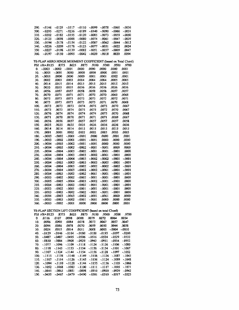
290. -.0146 -.0129 -.0117 -.0110 -.0099 -.0078 -.0060 -.0036
300. -.0295 -.0271 -.0236 -.0189 -.0140 -.0090 -.0060 -.0031
310. -.0202 -.0182 -.0155 -.0120 -.0085 -.0073 -.0059 -.0050
320. -.0125 -.0098 -.0088 -.0080 -.0074 -.0061 -.0047 -.0039
330. -.0194 -.0178 -.0154 -.0122 -.0087 -.0062 -.0044 -.0012
340. -.0226 -.0209 -.0178 -.0123 -.0077 -.0051 -.0022 .0024
350. -.0227 -.0198 -.0139 -.0082 -.0051 -.0037 -.0009 .0047
360. -.0197 -.0150 -.0095 -.0002 -.0020 -.0018 .0020 .0094
TE-FLAP AERO HINGE MOEMENT COEFFICIENT (based on Total Chord)
PSI r/R=.8125 .8375 .8625 .8875 .9100 .9300 .9500 .9700
O. -.0003 -.0002 -.0001 .0000 .0000 .0000 .0000 ,0001
10. -.0001 -.0001 .0000 .0000 .0000 .0000 .0001 .0001
20. -.0001 .0000 .0000 .0000 .0001 .0001 .0002 .0001
30. .0002 .0003 .0003 .0004 .0004 .0004 .0005 .0005
40. .0014 .0015 .0014 .0015 .0015 .0015 .0015 .0015
50. .0035 .0035 .0035 .0036 .0036 .0036 .0036 .0036
60. .0056 .0057 .0057 .0058 .0058 .0058 .0057 .0057
70. .0070 .0071 .0071 .0071 .0070 .0070 .0069 .0068
80. .0073 .0073 .0073 .0073 .0073 .0072 .0072 .0071
90. .0073 .0073 .0073 .0073 .0073 .0071 .0070 .0068
100. .0073 .0073 .0073 .0074 .0075 .0073 .0070 .0067
II0. .0073 .0073 .0074 .0075 .0075 .0072 .0070 .0067
120. .0076 .0074 .0074 .0074 .0074 .0073 .0070 .0068
130. .0071 .0070 .0070 .0071 .0071 .0071 .0069 .0067
140. .0056 .0056 .0057 .0057 .0057 .0057 .0057 .0058
150. .0035 .0035 .0035 .0035 .0036 .0036 .0036 .0036
160. .0014 .0014 .0014 .0015 .0015 .0015 .0015 .0015
170. .0001 .0001 .0002 .0002 .0002 .0003 .0003 .0003
180. -.0003 -.0002 -.0001 -.0001 .0000 .0000 .0001 .0001
190. -.0003 -.0002 -.0001 -.0001 -.0001 .0000 .0000 .0000
200. -.0000 -.0003 -.0002 -.0001 -.0001 .0000 .0000 .0000
210. -.0000 -.0003 -.0002 -.0002 -.0001 -.0001 .0000 .0000
220. -.0000 -.0000 -.0003 -.0002 -.0001 -.0001 -.0001 .0000
230. -.0000 -.0004 -.0003 -.0003 -.0002 -.0001 -.0001 .0000
240. -.0000 -.0004 -.0004 -.0003 -.0002 -.0002 -.0001 -.O001
250. -.0004 -.0003 -.0003 -.0003 -.0003 -.0002 -.0001 -.0001
260. -.0000 -.0004 -.0003 -.0002 -.0002 -.0002 -.0002 -.0001
270. -.0000 -.0004 -.0003 -.0002 -.0002 -.0001 -.0001 -.0001
280. -.0000 -.0003 -.0002 -.0002 -.0001 -.0001 -.0001 -.0001
290. -.0003 -.0002 -.0002 -.0002 -.0001 -.0001 -.0001 .0000
300. -.0005 -.0005 -.0004 -.0003 -.0002 -.0001 -.0001 .0000
310. -,0000 -.0003 -.0003 -.0002 -.0001 -.0001 -.0001 -.0001
320, -.0003 -.0002 -.0001 -.0001 -.0001 -.0001 -.0001 .0000
330. -.0003 -.0003 -.0002 -.0002 -.0001 -.0001 -.0001 .0000
340. -.0004 -.0003 -.0003 -.0002 -.0001 -.0001 .0000 .0000
350. -.0003 -.0003 -.0002 -.0001 -.0001 .0000 .0000 .0000
360. -.0003 -.0002 -.0001 .0000 .0000 .0000 .0000 .0001
TE-FLAP SECTION LIFT COEFFICIENT(based on tomlChord)
PSI r/R=.8125 .8375 .8625 .8875 .9100 .9300 .9500 .9700
0. .0116 .0107 .0098 .0088 .0079 .0072 .0064 .0054
10. .0096 .0090 .0084 .0078 .0073 .0067 .0057 .0047
20. .0094 .0086 .0078 .0070 .0059 .0050 .0044 .0038
30. .0024 .0015 .0014 .0011 .0008 .0005 -.0004 -.0010
40. -.0129 -.0146 -.0164 -.0180 -.0188 -.0193 -.0197 -.0200
50. -.0087 -.0087 -.0095 -.0506 -.0516 -.0524 -.0529 -.0533
60. -.0850 -.0884 -.0908 -.0929 -.0943 -.0951 -.0954 -.0952
70. -.1077 -.1096 -.1109 -.1118 -.1124 -.1126 -.1106 -.1080
80. -.1118 -.1143 -.1153 -.1154 -.1156 -.1134 -.1101 -.1067
90. -.1107 -.1124 -.1144 -.1154 -.1156 -.1128 -.1097 -.1052
100. -.1115 -.1138 -.1148 -.1149 -.1156 -.1126 -.1087 -.1003
110. -.1107 -.1114 -.1126 -.1145 -.!156 -.1124 -.1089 -,1048
120. -.1094 -.I110 -.1128 -.1144 -.1155 -.1136 -.!105 -.1066
130. -.1052 -.1068 -.1083 -.1100 -.1111 -.1117 -.1095 -.1071
140. -.0845 -.0863 -.0881 -.0898 -.0910 -.0920 -.0929 -.0942
150. -.0455 -.0467 -.0079 -.0090 -.0501 -.0510 -.0517 -.0523
73

160. -.0118 -.0127 -.0138 -.0147 -.0155 -.0163 -.0171 -.0179
170. .0070 .0059 .0048 .0039 .0031 .0024 .0015 .0006180. .0113 .0100 .0089 .0079 .0071 .0063 .0055 .0046
190. .0119 .0108 .0095 .0084 .0075 .0067 .0058 .0049
200. .0126 .0114 .0103 .0090 .0080 .0072 .0062 .0052210. .0131 .0119 .0108 .0096 .0085 .0075 .0065 .0054
220. .0133 .0125 .0113 .0101 .0090 .0079 .0069 .0057230. .0131 .0130 .0121 .0109 .0097 .0086 .0075 .0061
240. .0120 .0127 .0128 .0118 .0107 .0095 .0082 .0067250. .0118 .0112 .0116 .0120 .0114 .0104 .0090 .0073
260. .0127 .0115 .0104 .0100 .0104 .0104 .0095 .0079270. .0117 .0118 .0112 .0102 .0092 .0085 .0081 .0075
280. .0120 .0108 .0098 .0091 .0087 .0083 .0075 .0064290. .0096 .0092 .0091 .0092 .0090 .0084 .0075 .0063300. .0151 .0141 .0128 .0113 .0099 .0087 .0074 .0061
310. .0118 .0110 .0101 .0091 .0082 .0073 .0063 .0052320. .0084 .0071 .0067 .0065 .0063 .0061 .0057 .0051
330. .0114 .0109 .0103 .0095 .0087 .0079 .0069 .0058
340. .0124 .0119 .0110 .0098 .0085 .0076 .0066 .0056
350. .0124 .0116 .0103 .0091 .0082 .0075 .0067 .0058360. .0116 .0107 .0098 .0088 .0079 .0072 .0064 .0054
SECTION DRAG COEFFICIENT INCREMENT (oas¢don flapChord)PSl r/Rffi.8125.8375 .8625 .8875 .9100 .9300 .9500 .97000. .0000 .0000 .0000 .0000 .0000 .0000 .0000 .0000
10. .0000 ,0000 .0000 .0000 .0000 .0000 .0000 .000020. .0000 .0000 .0000 .0000 .0000 .0000 .0000 .000030. .0000 .0000 .0000 .0000 .0000 .0000 .0000 .0000
40. .0000 .0000 .000(3 .0000 .0000 .0000 .0000 .000050. .0000 .0000 .0000 .0000 .0000 .0000 .0000 .0000
360. .0000 .0000 .0000 .0000 .0000 .0000 .0000 .0000
SECTION MOMENT COEFFICIENT INCREMENT (basedon flapChord)PSI r/Rffi.8125.8375 .8625 .8875 .9100 .9300 .9500 .9700
0. .0000 .0000 .0000 .0000 .0000 .0000 .0000 .0000
10. .0000 .0000 .0000 .0000 .0000 .0000 .0000 .000020. .0000 .0000 .0000 .0000 .0000 .0000 .0000 .0000
30. .0000 .0000 .0000 ,0000 .0000 .0000 .0000 .000040. .0000 .0000 .0000 .0000 .0000 .0000 .0000 .0000
50. .0000 .0000 .0000 .0000 .0000 .0000 .0000 .0000
360. .0000 .0000 .0000 .0000 .0000 .0000 .0000 .0000
TE-FLAP SECTION INERTIA LOAD, LB/FTPSI r/Rffi.8125 .8375 .8625 .8875 .9100 .9300 .9500 .9700
0. .0000 .0000 .0000 .0000 .0000 .0000 .0000 .000010. .0000 .0000 .0000 .0000 .0000 .0000 .0000 .000020. .0000 .0000 .0000 .0000 .0000 .0000 .0000 .000030. .0000 .0000 .0000 .0000 .0000 .0000 .0000 .000040. .0000 .0000 .0000 .0000 .0000 .0000 .0000 .000050. .0000 .0000 .0000 .0000 .0000 .0000 .0000 .0000
360. .0000 .0000 .0000 .0000 .0000 .0000 .0000 .00(30
TE-FLAP SECTION INERTIAL HINGE MOMENT, FT-LJ3/FTPSI r/R=.8125 .8375 .8625 .8875 .9100 .9300 .9500 .9700
0. .0000 .0000 .0000 .000(3 .0000 .0000 .0000 .000010. .0000 .0000 .0000 .0000 .0000 .0000 .0000 .000020. .0000 .0000 .0000 .0000 .0000 .0000 .0000 .000030. .0000 .0000 .00C0 .0000 .0000 .0000 .0000 .0000
74
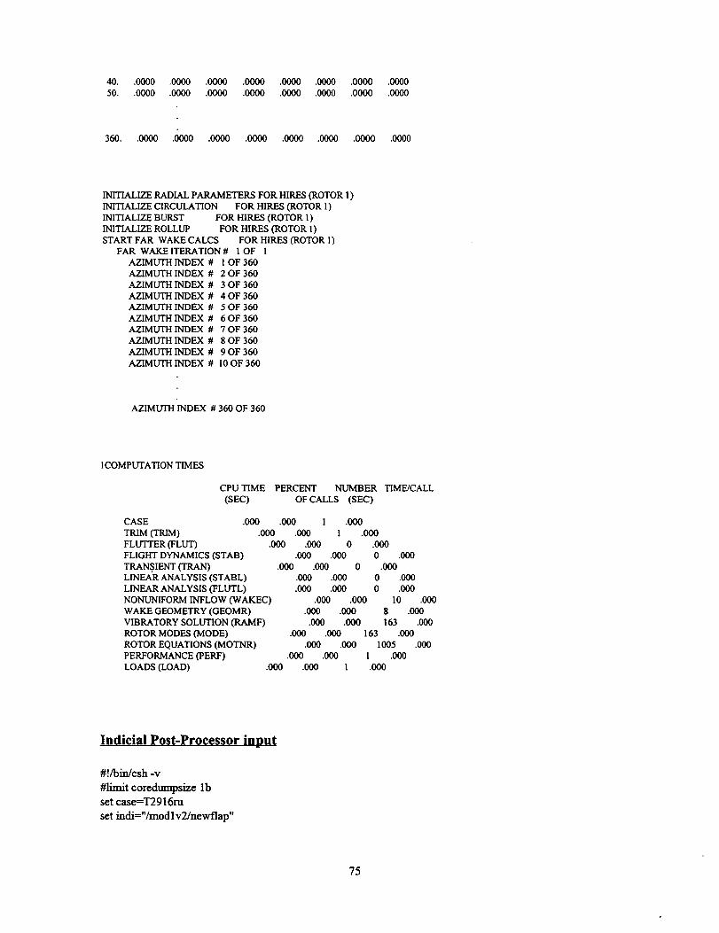
40. .6000.0000.0000 .0000.0600.0000.000(3.006050. .0600.0060.0000 .0000.0000.6000.0000 .0060
360. .0000._0 .0000.0000.0000.6000.0000 ._0
INITIALIZE RADIAL PARAMETERS FOR HIRES (ROTOR 1)
INITIALIZE CIRCULATION FOR HIRES (ROTOR 1)INITIALIZE BURST FOR HIRES (ROTOR l )INITIALIZE ROLLUP FOR HIRES (ROTOR l)START FAR WAKE CALCS FOR HlRES (ROTOR I)
FAR WAKE ITERATION # l OF IAZIMUTH INDEX # ! OF 360AZIMUTH INDEX # 2 OF 360
AZIMUTH INDEX # 3 OF 360AZIMUTH INDEX # 4 OF 360
AZIMUTH INDEX # 5 OF 360AZIMUTH INDEX # 6 OF 360
AZIMUTH INDEX # 7 OF 360AZIMUTH INDEX # 8 OF 360
AZIMUTH INDEX # 9 OF 360AZIMUTH INDEX # I0OF 360
AZIMUTH INDEX # 360 OF 360
1COMPUTATION TIMES
CPU TIME PERCENT NUMBER TIME/CALL
(SEC) OF CALLS (SEC)
CASE
TRIM (TRIM)FLUTTER (FLUT)FLIGHT DYNAMICS (STAB)
TRAN .SIENT (TRAN)LINEAR ANALYSIS (STABL)
LINEAR ANALYSIS (FLUTL)NONUNIFORM INFLOW (WAKEC)
WAKE GEOMETRY (GEOMR)VIBRATORY SOLUTION (RAMF)
ROTOR MODES (MODE)ROTOR EQUATIONS (MOTNR)
PERFORMANCE (PERF)LOADS (LOAD) .000
.000 .000 I .000
.000 .000 1 .000.600 .600 0 .600
.600 .000 0 .600.000 .060 0 .600
.600 .600 0 .600
.000 .000 0 .060.000 .000 I0 .060
8 .600163 .600
163 .6001005 .000
1 .060
.000
.600 .600.060 .000
.600 .060.060 .000
.060 .060.600 1
Indicial Post-Processor input
#!/bin/csh -v
#limit coredumpsize lbset case=T2916ru
set indi="/mod 1v2/newflap"
75

set airf=-"/mod 1v2/Langley/AF_rotor/C81FT"echo link airfoil table
# link airfoil table
In -s $airf/0015ahft.tab fro20echo run indicial
#
# input RADIUS, SOUND, DENSE in metric so that# N/m results.
#
lime $indi/mdic_doug-sf- 1 >& indic_$ {case}.out <<¢oj&INLST
FWFILE = '../int_$ {case}.dat',
VINDFILE = '../vind_$ {case}.dat',NRAD = 70
= 360
= 1074.01
= 1.84785
= 335.7585
= 1•258
=.1347082•1347082.1347082.1347082.1347082.1347082.1347082.1347082.1347082.1347082.1347082.1347082.1347082
NAZM
RPM
RADIUS
SOUND
DENSE
CHORD
•1347082.1347082
.1347082
.1347082
•1347082
.1347082
.1347082
.1347082
.1347082
.0.0.0.0
.0.0.0.0
RAE
.3899999
•4799999
.5799999
.6899999
•79.8•81
•8999999
•0.0.0.0
.0.0.0.0
•1347082.1347082
.1347082.1347082
•1347082.1347082
.1347082.1347082
.1347082.1347082
.1347082.1347082
.1347082
• 1347082
.0.0.0.0
.0
.1347082.1347082
.1347082.1347082
.1347082.1347082
.1347082.1347082
.1347082.1347082
.1347082.1347082
.1347082.1347082
.1347082.1347082
.1347082.1347082
.1347082.1347082
.1347082.1347082
.1347082.1347082•1347082 .1347082 .1347082 . 1347082 .1347082
.1347082.1347082.1347082.1347082.1347082.0.0
.0.0.0.0.0.0.0.0.0.0.0.0.0.0.0
= .2924999.3.31.3199999.33.34.3499999.36.37.3799999
.4 •4099999.4199999.43.4399999.4499999.46 •4699999
.49.5.5099999.5199999.5299999.54.55.56 •5699999
.5899999.6.61.62 •6299999.6399999.6499999.66.67.68
•6999999.7099999.72.73.74.75.7599999.7699999.7799999
•8199999.8299999.8399999.85.86.87 •8799999 •8899999
.91.92.93 •9399999.9499999 •9599999.97.98 1.0.0.0.0
.0.0.0.0.0.0.0.0.0.0.0.0.0.0.0.0.0.0.0
SWP =.0.0.0.0.0.0.0.0.0.0_.0.0.0.0.0.0.0.0.0.0.0.0.0.0.0.0.0.0.0.0.0.0.0.0.0.0.0.0.0.0.0.0.0
.0.0.0.0.0.0.0.0.0.0.0.0.0.0.0.0.0.0.0.0.0.0.0
.0.0.0.0.0.0.0.0.0.0.0.0.0.0.0.0.0.0.0.0.0.0.0
.0.0.0.0.0.0.0.0.0.0
_1,_ap= 51"0.,18"1.,0.iload=2
&END
e_echo_ncin_cml
#unl_tcoredumps_ee_
76

Form ApprovedREPORT DOCUMENTATION PAGE OMBNo.0_04-018s
Publlc reporting burden for this collection of information is eatlmatad to average 1 hour per response, including the time for reviewing instructions, searching existing data sourcesga_ertng and maintaining the data needed, and comp_ating and reviewing the co_lantion of information, Send comments regarding this burden estimate or any other aspect of thi_collection of Information, including suggestions for reducing this burden, to Washington Headquarters Services, Directorate for Infocmation Opera_ons and Reports, 1215 JefforsorDavis Highway, Suite 1204, Art_ngton, VAt22202-4302, end to the Office of Management and Budget, Paperwork Reduction Project (0704-0188), Washington, DC 20503.
1. AGENCY USE ONLY (Leeve blank) 2. REPORT DATE 3. REPORT TYPE AND DATES COVERED
May 1999 Contractor Report4. TITLE AND SUBTITLE 5. FUNDING NUMBERS
Implementation of a Trailing-Edge Flap Analysis Model in the NASALangley CAMRAD.MOD1/HIRES Program
6. AUTHOR(S)
Bruce Charles
7. PERFORMING ORGANIZATION NAME(S) AND ADDRESS(ES)
The Boeing CompanyMesa, Arizona
9. SPONSORING/MONITORING AGENCY NAME(S) AND ADDRESS(ES)
National Aeronautics and Space AdministrationLangley Research CenterHampton, VA 23681-2199
NAS 1-20096 Task 14
WU 538-07-14-10
8. PERFORMING ORGANIZATIONREPORT NUMBER
10. SPONSORING/MONITORING
AGENCY REPORT NUMBER
NASA/CR- 1999-209327
11.SUPPLEMENTARYNOTES
Langley Technical Monitor: Henry E. Jones
12a. DISTRIBUTION/AVAILABILITY STATEMENT
Unclassified-Unlimited
Subject Category 71 Distribution: NonstandardAvailability: NASA CASI (301) 621-0390
12b. DISTRIBUTION CODE
13. ABSTRACT (Maximum 200 words)
Continual advances in rotorcraft performance, vibration and acoustic characteristics are being sought by total-wing vehicle manufacturers to improve efficiency, handling qualities and community noise acceptance of theirproducts. The rotor system aerodynamic and dynamic behavior are among the key factors which must be addressedto meet the desired goals. Rotor aerodynamicists study how airload redistribution impacts performance and noise,and seek ways to achieve better airload distribution through changes in local aerodynamic response characteristics.One method currently receiving attention is the use of trailing-edge flaps mounted on the rotor blades to providedirect control of a portion of the spanwise lift characteristics. The following work describes the incorporation of atrailing-edge flap model in the CAMRAD.MOdl/HIRES comprehensive rotorcraft analysis code. The CAM-RAD.Modl/HIRES analysis consists of three separate executable codes. These include the comprehensive trimanalysis, CAMRAD.Modl, the Indicial Post-Processor, IPP, for high resolution aidoads, and AIRFOIL, which pro-duces the rotor airfoil tables from input airfoil section characteristics. The modifications made to these componentspermitting analysis of flapped rotor configurations are documented herein along with user instructions detailing thenew input variables and operational notes.
14. SUBJECT TERMS
Noise Reduction, Tiltrotor, Fiaps, Blade-Vortex Interaction
17. SECURITY CLASSIFICATION
OF REPORT
Unclassified
NSN 754001-280-5500
18. SECURITY CLASSIFICATION
OF THIS PAGE
Unclassified
15. NUMBER OF PAGES
8316. PRICE CODE
A05
19. SECURITY CLASSIFICATION 20. LIMITATION
OF ABSTRACT OF ABSTRACT
Unclassified UL
Standard Form 298 (Rev. 2-89)Prescnbed by ANSI Std, 239-18298-102


![NASA-CR-197272...and angle of attack [5].' At larger flap deflections, the flow over the flap separated. Off-the-surface separation was observed to limit the maximum obtainable lift](https://img.pdfslide.us/doc/110x75/5e63e7901b3a017de81cb293/nasa-cr-197272-and-angle-of-attack-5-at-larger-flap-deflections-the-flow.jpg)