Embed Size (px)
Citation preview
Chalmers University of Technology University of Gothenburg Department of Computer Science and Engineering Göteborg, Sweden, February 2014
Implementation of a real-time computer for space applications
Master of Science Thesis Embedded Electronic System Design
Oscar Siby

II
The Author grants to Chalmers University of Technology and University of Gothenburg the non-exclusive right to publish the Work electronically and in a non-commercial purpose make it accessible on the Internet. The Author warrants that he/she is the author to the Work, and warrants that the Work does not contain text, pictures or other material that violates copyright law. The Author shall, when transferring the rights of the Work to a third party (for example a publisher or a company), acknowledge the third party about this agreement. If the Author has signed a copyright agreement with a third party regarding the Work, the Author warrants hereby that he/she has obtained any necessary permission from this third party to let Chalmers University of Technology and University of Gothenburg store the Work electronically and make it accessible on the Internet.
Implementation of a real-time computer for space applications Master of Science thesis embedded electronic system design Oscar Siby © Oscar Siby, February 2014. Examiner: Per Larsson-Edefors Chalmers University of Technology University of Gothenburg Department of Computer Science and Engineering SE-412 96 Göteborg Sweden Telephone + 46 (0)31-772 1000 Department of Computer Science and Engineering Göteborg, Sweden February 2014
III
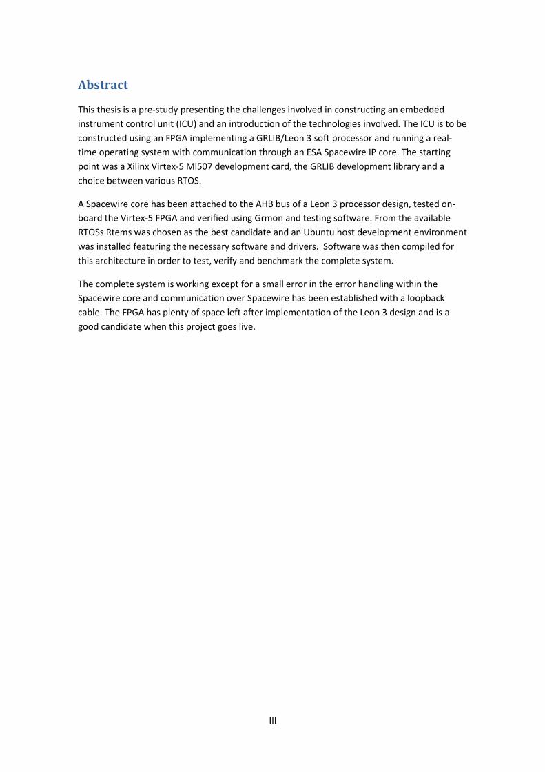
Abstract
This thesis is a pre-study presenting the challenges involved in constructing an embedded
instrument control unit (ICU) and an introduction of the technologies involved. The ICU is to be
constructed using an FPGA implementing a GRLIB/Leon 3 soft processor and running a real-
time operating system with communication through an ESA Spacewire IP core. The starting
point was a Xilinx Virtex-5 Ml507 development card, the GRLIB development library and a
choice between various RTOS.
A Spacewire core has been attached to the AHB bus of a Leon 3 processor design, tested on-
board the Virtex-5 FPGA and verified using Grmon and testing software. From the available
RTOSs Rtems was chosen as the best candidate and an Ubuntu host development environment
was installed featuring the necessary software and drivers. Software was then compiled for
this architecture in order to test, verify and benchmark the complete system.
The complete system is working except for a small error in the error handling within the
Spacewire core and communication over Spacewire has been established with a loopback
cable. The FPGA has plenty of space left after implementation of the Leon 3 design and is a
good candidate when this project goes live.

IV

1
Acknowledgements
First I would like to thank Omnisys instruments for offering this exciting Master Thesis and
especially Mats Wannerbratt who was the project leader. Also I would give thanks to my
supervisors at Omnisys Mikael Krus and Kalle Kempe who were available for answers and
finally I would like to thank my supervisor and examiner at Chalmers: Per Larsson-Edefors for
valuable advice and help.

2
Table of Contents 1 Introduction .......................................................................................................................... 4
1.1 Aim ................................................................................................................................ 5
1.2 Thesis outline ................................................................................................................ 5
1.3 Materials and Equipment .............................................................................................. 6
2 Technical Background ........................................................................................................... 7
2.1 Xilinx and Virtex-5 ......................................................................................................... 7
2.2 Gaisler and GRLIB .......................................................................................................... 8
2.3 Spacewire and Opencores ........................................................................................... 10
3 Real-Time Operating systems.............................................................................................. 12
3.1 Rtems........................................................................................................................... 12
4 Implementation and verification ........................................................................................ 14
4.1 Leon 3 .......................................................................................................................... 14
4.2 The Spacewire_light Peripheral .................................................................................. 17
4.3 Building Rtems cross compilation tools ...................................................................... 21
4.4 Compiling and testing operating system ..................................................................... 22
4.5 Testing the complete system ...................................................................................... 23
5 Results ................................................................................................................................. 27
6 Conclusion ........................................................................................................................... 27
6.1 Future works ............................................................................................................... 28
Bibliography ................................................................................................................................ 29
Appendix ..................................................................................................................................... 31

3
Glossary
AMBA – Advanced microcontroller bus architecture
API – Application programming interface
BSP – Build support package
CLB - Configurable logic blocks
ESA – European space agency
EDA – Electronic design automation
FPGA – Field programmable gate array
GRLIB – Gaisler research IP library
ISR – Interrupt service routine
ICU – Instrument control unit
JTAG – Joint task action group
LGPL – Lesser general public license
OSI model – Open systems interconnection model
RTOS – Real time operating system
RPM – Red hat package manager
Spacewire – Space communication standard
VHDL – VHSIC hardware description language
XGI – Xilinx generic interface

4
1 Introduction
This Master thesis is being conducted in cooperation with the company Omnisys Instruments
who are developing a Stratosphere-Troposphere Exchange and climate Monitor Radiometer:
STEAMR [1] which is an instrument used for atmospheric research. Omnisys Instruments are
the prime contractor for the instrument and responsible for optics, control software and
system tests and are currently performing a breadboard study, demonstrating the key features
of the instrument. Omnisys’s scope of the instrument is the front-end including LO-, IF- and
phase-lock system, the digital autocorrelator, back-end quad receivers, the power distribution
and control hardware [2]. This system is to be mounted on a satellite in the near future and in
that process the system needs to be space worthy and an instrument control unit (ICU) needs
to be implemented in hardware for the back-end control system, a rough sketch of the back-
end system is shown in Figure 1.
Figure 1: Current redundant system schematic
This Master thesis is designed as a pre-study to learn more about which technologies and what
kind of system is required for this embedded ICU to function in this context. The starting point
of this pre-study is a Xilinx Virtex-5 development board described in chapter 2.1, a
LEON3/GRLIB soft processor design plus necessary peripherals described more in detail in

5
chapter 2.2 and 2.3. A real time operating system will then be implemented and tested with
I/O functions over a Spacewire communication protocol [6] which is described in chapter 2.3.
1.1 Aim The aim of the project is to investigate whether a Leon 3 core realised on a FPGA, a RTOS and
Spacewire peripheral can work together. Since the system this ICU will be placed in has yet
been fully designed there is no explicit hardware requirements, this means measuring the
performance of the involved hardware is not a primary concern as long as the components can
be realised and the software can execute with decent responsiveness. When it comes to the
capabilities of an RTOS the priorities are thread and scheduling control, size of the kernel and
compiled programs and finally its response times. This means running test and benchmarking
software to verify and evaluate the RTOS while it is executing on the development board. In
successive order the four goals are:
-Determine if the Xilinx Virtex-5 FPGA is sufficient; evaluate the capabilities of Leon/GRLIB and
the possible RTOS:es.
-Implement the Leon 3 soft processor and the necessary IP cores for Spacewire communication
on the Xilinx development board using VHDL.
- Implement the chosen RTOS by having it running on the soft core and testing out its features.
- Testing and benchmarking the system as a whole by developing and running software that
measures its capabilities.
Also of prime importance is how well the tools and development environments for Leon 3 and
chosen RTOS work, if they are easy to use and set up, whether they require extra software and
so forth.
1.2 Thesis outline This project was performed with a mix of theoretical studies and hardware/software
development. The first steps were getting to know these components, to understand how they
work and how they fit into the big puzzle. After getting a system wide overview I could then
proceed with design and implementation. Therefore Chapter 1.3 lists the involved hardware
and software components, after which I in chapter 2 and 3 relate to these components with
specifications and technical-backgrounds revealing my findings. Chapter 4 will then walk
through the hardware and software development steps, display the current benchmarking
results and how testing of the complete system was performed. Chapter 5 displays the results
in accordance to the goals and finally chapters six includes conclusions and future work.
6
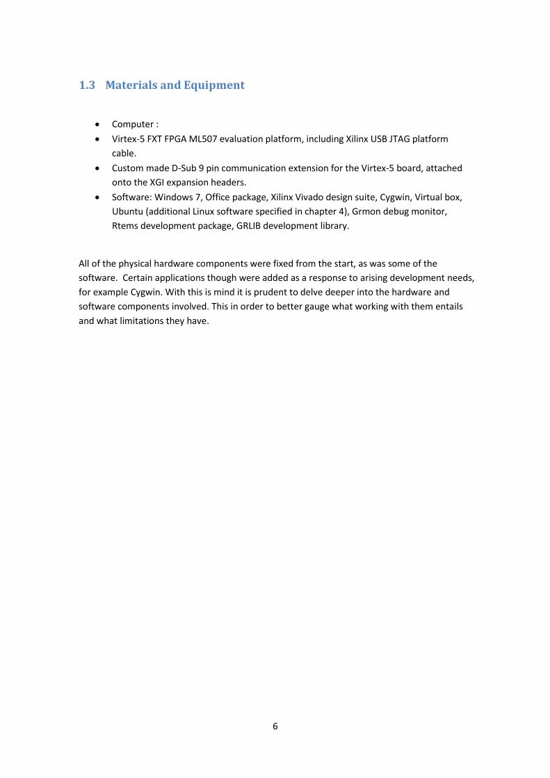
1.3 Materials and Equipment
Computer :
Virtex-5 FXT FPGA ML507 evaluation platform, including Xilinx USB JTAG platform
cable.
Custom made D-Sub 9 pin communication extension for the Virtex-5 board, attached
onto the XGI expansion headers.
Software: Windows 7, Office package, Xilinx Vivado design suite, Cygwin, Virtual box,
Ubuntu (additional Linux software specified in chapter 4), Grmon debug monitor,
Rtems development package, GRLIB development library.
All of the physical hardware components were fixed from the start, as was some of the
software. Certain applications though were added as a response to arising development needs,
for example Cygwin. With this is mind it is prudent to delve deeper into the hardware and
software components involved. This in order to better gauge what working with them entails
and what limitations they have.

7
2 Technical Background
This chapter will introduce Xilinx along with the Virtex-5 development board and describe its
features and limitations. It will continue to describe GRLIB and how this IP Core Library
operates. Finally we will look at Opencores and the Spacewire VHDL core.
2.1 Xilinx and Virtex-5 Xilinx invented FPGAs and the programmable logic circuit. They are a fabless semiconductor
company specialized towards FPGAs and CPLDs where their products span the whole design
chain. They design, develop and market programmable logic circuits, ICs, design tools and
specialized hardware delivered as IP, as well as all other services required such as technical
support, field engineering, customer training and design services.
They have a large number of FPGAs available in various packages ranging from fully
customized to premade development platforms; the one used in this study is a Virtex-5 FXT
FPGA ML507 evaluation platform. Omnisys had several platforms that could be used but this
one was the most powerful and offered synergies with other components in this project
(Spacewire Core). These development platforms provide out of the box design solutions and
contain everything you need to rapidly start the development process. This specific board
contains a long list of features and components [3], most importantly the Virtex-5 FPGA core
and a supporting PowerPC 440 Microprocessor. The board also features cross-platform
compatibility, system monitoring and supports the most common communication interfaces
such as USB and Ethernet.

8
Figure 2: Virtex-5 ML507 development board [19]
While the features give an idea of what the board can do other variables within the FPGA core
have significant impact on performance such as CLB slices, DSP slices, RAM Blocks, Clock
Management Blocks (CMTs) and total I/O banks. This data shows what can be realised on the
FPGA and according to board specifications it has 11,200 CLB slices, 128 DSP slices, maximum
of 5328 kB of RAM, 6 CMTs and 19 I/O banks. The ML507 was a high performance board in the
Virtex-5 series when it was launched, today it is marked as legacy and when comparing to
today’s top of the line FPGAs it is considered small. The biggest Virtex-7 model features over
300k CLB slices.
2.2 Gaisler and GRLIB Aeroflex Gaisler is a company that produces IP cores and development tools for embedded
processors, specifically those based on SPARC architectures. The company is based in
Gothenburg Sweden and has a diverse portfolio, where the full source codes for some
products are available for free under the GNU GPL Licence while others have to be bought and
paid for.
In the centre of their work lies GRLIB [4] which is an integrated set of reusable IP cores used in
System on a chip development. These IP cores are organized around VHDL libraries sorted by
vendor or by specific technologies, the library as a whole uses coherent methods for
simulation and synthesis while being vendor independent and supports a broad range of CAD

9
tools and target technologies.
Figure 3: GRLIB tree structure [20]
The whole creation process can be handled through automated global makefiles that can also
generate simulation/synthesis script files for most development tools. GRLIB also follows a
plug & play fashion where adding and removing packages or libraries from the structure only
requires modifying text files in the hierarchy.
GRLIB contains several versions of the LEON soft processor, a 32 bit processor based on the
SPARC v8 architecture. Leon 3 is the only core included in the open source version of GRLIB but
the Leon 2 can also be bought as a fault-tolerant version and is available in radiation
hardened components from Atmel. The Leon 4 is an evolved version of Leon 3 and is only
available by purchasing a license.
All Leon cores are highly configurable and built in a bus-centric fashion where most
components in the design are or will be connected through the AMBA-2.0 AHB or APB. What
components to be used in a specific design are purely optional and can easily be modified
using Xconfig or through straight VHDL modifications. Xconfig is a GUI tool made by Gaisler and
is included in GRLIB, it is used to create and configure the Config.vhd file for Leon 3 template
designs.
AMBA v2.0 [5] is an ARM multi-master bus design that can be used for free and has been
implemented according to specifications with additional sideband signals for address decoding,
interrupt steering and device identification. All attached units are split into masters and slaves
and are controlled by a global bus arbiter, address decoder and bus multiplexer that selects
which master and slave that are currently active.

10
Figure 4: Leon 3 template design [21]
The Leon 3 [6] processor is built on the SPARC v8 [7] instruction set with the V8e extensions
and uses a seven stage pipeline. It includes hardware multiply-, divide-, MAC units and a fully
pipelined IEEE-754 floating point unit. A great feature of soft processors is the flexibility, when
using GRLIB all caches and memory sizes are easily configurable and subject to the designers
decision. GRLIB also include on-chip debug support units with instruction and data trace
buffers that can be attached to the AHB bus. This debug unit can be connected to a Gaisler
developed tool called Grmon to significantly ease debugging and with which software can be
loaded onto the FPGA. The Leon 3 processor design caps at 125 MHz in FPGAs.
GRLIB contains template designs for many of the common development platforms and a
configuration and development guide is available that describes how to design other versions
of the Leon processor using Xconfig. Each template is based on three files: Leon3mp.vhd,
Config.vhd and Testbench.vhd with the first one being the top-level design entity which
instantiates the IP cores used in that specific design. Config.vhd contains all the configuration
parameters set by Xconfig while Testbench.vhd is a testbench built to simulate the design.
2.3 Spacewire and Opencores Spacewire is a high-speed space communication standard defined in the ESA standard ECSS-E-
ST-50-12C [8]. It was authored by Steve Parks from the University of Dundee in collaboration
with the ESA Spacewire working group which include European space industry, academia and
NASA. The standard works on the first two layers of the OSI model (physical- and data-link
layers) with the goal of achieving low-cost, low-latency, full-duplex point to point
communication through packet switching wormhole routers. The standard encompasses

11
speeds between 2 – 400 Mb/s and components included are physical connectors and cables,
electrical properties and logical protocols within the data link.
Opencores is an online community set up to host and further advance open source hardware
projects; it is a forum for developers and enthusiasts to share knowledge and technology
where all projects are available as open source under LGPL or GPL. Opencores was started as
the OpenRISC project in 1999 by a group of Slovenian students who aimed at creating an open
source microprocessor architecture. After two years they had produced architectural
specifications, a simulator and a VHDL implementation. All this they launched through their
new community Opencores as free software under GPL/LGPL. By joining this community a lot
of technology became available; among those a Spacewire encoder-decoder IP core with an
AMBA bus interface already tested in a Virtex-5 FPGA.
The Opencores Spacewire core is named Spacewire light and is written by Joris van Rantwjik
who also holds the copyright distributes under GPL. The core contains several entities
including a receiver, a transmitter, two application interfaces and a link state machine. There
are two top level entities that are contained within Spwstream.vhd and Spwamba.vhd to use
either connected to an AMBA bus or as a separate core.
The next chapter will look into the software that is going to run on these hardware
components and what an RTOS is and explain the software components involved.

12
3 Real-Time Operating systems (RTOSs)
Real time embedded system are today’s bread and butter and can be found practically
everywhere in our daily lives ranging from telephones to kitchen appliances. Combine this with
a rapidly changing technological environment and technological advancements and it’s easy to
understand why it is difficult to define exactly what a real time embedded system is. What can
be said though is that the most distinguishing rule that separates these from other software
applications is that they are driven by and must respond to real world events. The correctness
of the system depends on when a result is produced, thus the system must keep timing
requirements while adhering to various other requirements set by the environment that they
interact with and responding to external stimuli.
When developing software for embedded systems it is usually done in a cross development
environment. That means compiling the software in one system which is called the host
system while executing on another system the target platform. Often the requirements for the
target system are incompatible or in direct conflict with the build host system. That means
setting up a specialized environment with the correct provisions for the target board including
tools, initialization code, drivers and error handling code. The host system is generally a
general purpose workstation built for flexibility and with much greater resources while the
target system has limited resources built for a specific task or function.
When it comes to RTOS for the Leon 3 processor Gaisler keeps a list of which systems that
maintain active support for their processor, both commercial and open source versions are
available. Although one of the project goals was to look at all candidates, it quickly became
apparent that Rtems was the only viable candidate. This due to several factors, but most
importantly that only open source systems were financially viable in this project and that the
Spacewire core already had drivers for Rtems which would speed up development significantly.
Other candidates mentioned by Gaisler were VxWorks, Thread X, Nucleus, LynxOs, Snapgear
Linux and eCos [9].
3.1 Rtems Real-Time Executive for Multiprocessor Systems is a free open source RTOS created for
embedded systems use and its designed started in the late 1980 with early versions available
in 1993. Currently OAR Corporation is managing the Rtems project in cooperation with a
steering committee. Rtems is fully built around the open-source concept supporting various
open API standards such as POSIX and BSD sockets while supporting file systems such as NFS
and FAT. In POSIX terms Rtems implements a single process, multithreaded environment and
as such does not provide any process forking services. It supports a wide range of architectures
among them SPARC and the LEON designs. While Gaisler provides an Rtems port and cross-
compilation system called RCC the original Rtems version will be used in this project due to the
spw_light being built for the original. Rtems also comes with a wide range drivers and the

13
cross-compilation environment is built akin to GRLIB with Makefiles. The programming
language in question is C and the compiler being used is GCC. The kernel is very flexible and
what drivers or functions brought in is determined by define macros in the compiled code.
Similarly to GRLIB, Rtems is built for a Linux environment with automake and autoconf and
heavily relies on makefiles. The community around Rtems is very active with several mail
groups and forums available to answer questions should the need arise.
This concludes the Technical background and the next part contains the Implementation and
verification of the hardware and software.

14
4 Implementation and verification
With the goals of this project already outlined, the implementation part started with questions
of varying priority that arose and needed answers. This a project really split into two parts,
software development and hardware development and the tasks are layered, meaning some
tasks need to be finished before others can be started. The first big question was related to the
hardware: would Leon 3 with peripherals fit onto this specific Virtex-5 FPGA? Second, are there
Leon 3 designs available from GRLIB for this board or will I need to design one from scratch?
And related to that why use this specific soft processor? There are a variety of them out there.
It turns out the reason for choosing Leon 3 and GRLIB has to do with reliability and confidence,
when it comes to products bound for space the hitch is if things break down it is a real hassle
to repair or replace components. Since GRLIB has been featured in numerous space going
missions [10] it has been tested and proven to work in space environments. Furthermore,
GRLIB also contains a Spacewire core (requires a commercial license) and has a verified list of
functional RTOS for their architecture. In this industry GRLIB is regarded as a safe and reliable
component in any system. To answer the two first questions I needed to start developing with
GRLIB.
4.1 Leon 3 GRLIB comes with comprehensive manuals detailing everything within the GRLIB domain
among them a quick start guide explaining the installation paths/environments available. As
mentioned earlier GRLIB development is built around a hierarchical system of GNU makefiles
built for Linux. My currently installed environment is windows 7 which made me try a
translation API named Cygwin [11] that the guide mentioned. This is a nifty program that
provides significant Linux API functionality for windows and worked out perfectly except for
one small detail which I was never able to fix: the Xconfig tool provided with GRLIB behaved
quite strangely within the Cygwin environment: It wasn’t able to save any of the created
configurations, it only every printed out an empty Config.vhd file. I spent some time trying to
solve this problem but instead ended up installing Ubuntu Linux under a virtual machine using
Virtual box from Oracle. Having Cygwin installed proved to have other advantages though,
since the rest of the Linux tools was working I could still use the rest of the GRLIB Makefile
scripts such as creating scripts, programming the FPGA or synthesizing the design. This was
especially helpful for the EDA steps that require a lot of computational power and could then
be run on the host system rather than on the virtual machine.
15
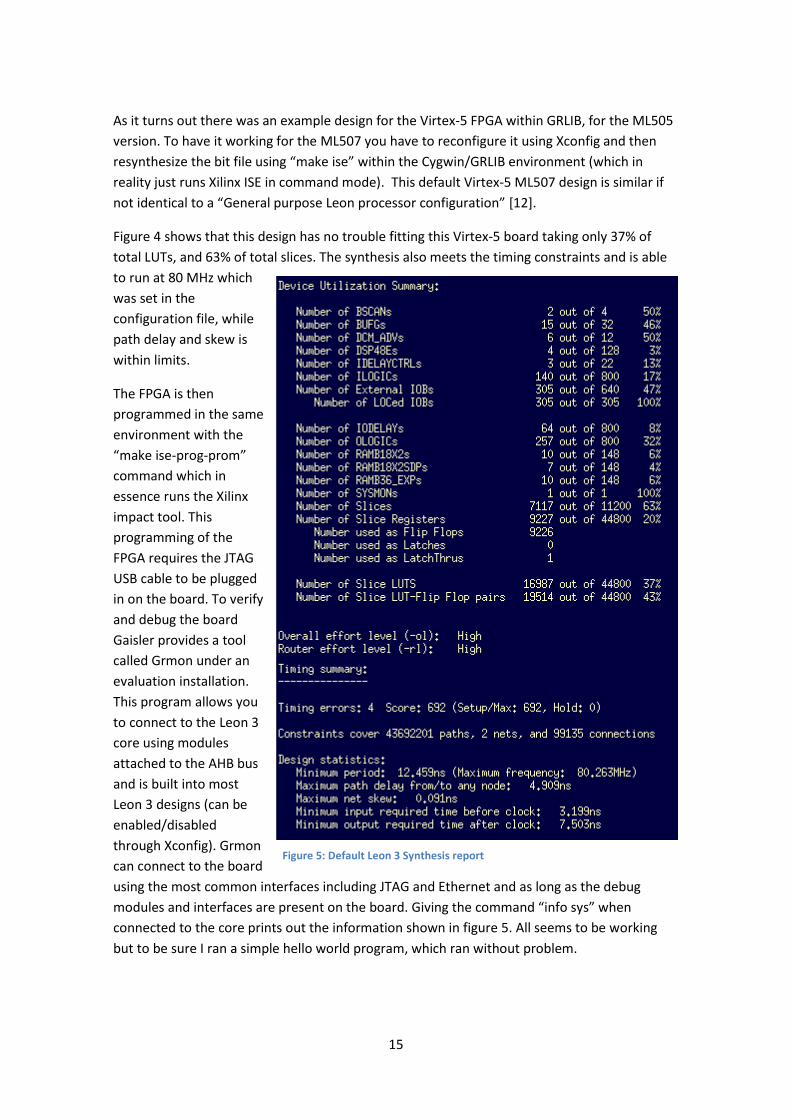
As it turns out there was an example design for the Virtex-5 FPGA within GRLIB, for the ML505
version. To have it working for the ML507 you have to reconfigure it using Xconfig and then
resynthesize the bit file using “make ise” within the Cygwin/GRLIB environment (which in
reality just runs Xilinx ISE in command mode). This default Virtex-5 ML507 design is similar if
not identical to a “General purpose Leon processor configuration” [12].
Figure 4 shows that this design has no trouble fitting this Virtex-5 board taking only 37% of
total LUTs, and 63% of total slices. The synthesis also meets the timing constraints and is able
to run at 80 MHz which
was set in the
configuration file, while
path delay and skew is
within limits.
The FPGA is then
programmed in the same
environment with the
“make ise-prog-prom”
command which in
essence runs the Xilinx
impact tool. This
programming of the
FPGA requires the JTAG
USB cable to be plugged
in on the board. To verify
and debug the board
Gaisler provides a tool
called Grmon under an
evaluation installation.
This program allows you
to connect to the Leon 3
core using modules
attached to the AHB bus
and is built into most
Leon 3 designs (can be
enabled/disabled
through Xconfig). Grmon
can connect to the board
using the most common interfaces including JTAG and Ethernet and as long as the debug
modules and interfaces are present on the board. Giving the command “info sys” when
connected to the core prints out the information shown in figure 5. All seems to be working
but to be sure I ran a simple hello world program, which ran without problem.
Figure 5: Default Leon 3 Synthesis report

16
Figure 6: Default Leon 3 configuration up and running
The next step was then attaching the Spacewire core onto the AHB bus to enable such
communication.

17
4.2 The Spacewire_light Peripheral The Spacewire_light archive included a manual that recommended integrating the core into
GRLIB in order to increase the accessibility and ease of use; this was done by copying the
Spacewire folder into the lib/opencores/ directory of the GRLIB hierarchy and then adding the
name of that folder to the lib/opencores/dirs.txt file. This makes all spw_light entities
accessible like any other GRLIB IP core.
Adding the spw_light core to the Leon 3 template design is a matter of instantiating the
spwamba entity inside the top level leon3mp entity and connecting it correctly to the AMBA
AHB bus while connecting the correct signals to it. The entity correctly connected to the AHB
bus is shown in Figure 4.
Figure 7: spwamba entity correctly connected to the AMBA buss
This core is supposed to communicate over wire with another computer or similar device and
therefore needs to be connected to a physical port of the development board. This
development board has no Spacewire ports built-in and instead had to be connected through
the XGI extension pins by attaching a custom built D-sub communication extension board that
Omnisys had available, shown in the figure 5.

18
Figure 8: Virtex-5 board with XGI extension
In order for this to work the entity that is realized in the FPGA must be connected to physical
outpads and inpads off the FPGA which require some extra code shown in Figure 6.
Figure 9: Connecting entity ports to FPGA outpads

19
Furthermore these FPGA outpads need to be directed towards the XGI headers, this is done by
connecting the above
shown signals to the
XGI headers physical
name in the
leon3mp.ucf file. This
proved to be a hassle
as the FPGA divide its
outpins into banks and
within each bank all
signals need to follow
the same I/O standard,
which for example
defines signal voltages.
The bank the XGI
header pads are
located in is fixed and
the same holds true for
the Ethernet pad
which requires
LVCMOS33 while
Spacewire uses
LVDS_25. Two of XGI
header pads and the
Ethernet pad were
located in the same
bank which made both
the topmost d-sub
connectors unusable.
Fortunately the bank
the lowermost two
where connected to
have no such collisions
and could be used by
the XGI extension board.
This design was then synthesized in the same manner as earlier and the results are shown in
figure 7. In the device utilization summary we can see that Sliced LUTs total has increased by
1319 while the Slices count has increased by 391. The synthesis is successful which implies is
has met the timing requirement of 80 MHz even though the timing summary mentions a max
frequency of 75 MHz.
For verification the FPGA was programmed and connected to using Grmon seen in figure 8.
Figure 10: Xilinx Device utilization summary of the Leon 3 design

20
Figure 11: Info sys information of Modified Leon 3 core
As can be seen in figure 8 the spw_core has been found on the AHB bus connected as master 5.
The next question was concerning the functionality of the core, would I need to modify the
processor core to improve performance? Is the new core working correctly? The decision on
how to proceed came down to work hours, there was still a lot of work to be done and how
well the Leon 3 core performs is not really an issue as long as it worked and it could be
improved if needed. Debugging and verifying that the core is working as intended should be
the next step, this could be done in several ways and I chose to do it through software rather
than with lengthy and time consuming hardware verification methods. This is usually a bad
choice but Opencores has marked it as a finished project; in its documentation it is noted that
they have previously had it working under a Virtex-5 system and provided in the package is
several testbenches that can be used to verify it. All this made me confident it should be
working as intended, testing and verifying would then be faster through software using the
chosen RTOS Rtems.

21
4.3 Building Rtems cross compilation tools The first step when starting development is constructing the host system for cross
development and there were a few important facts to consider. First Rtems can be distributed
in a few forms: first I noticed that for some Linux distributions already compiled releases were
available. Unfortunately there were none for Ubuntu hence a need to compile the necessary
tools from source. Secondly the source files are available through various mediums such as a
simple Zip file, but you could also clone a build version through a Git repository or let a RPM
file build one for you. For this project though an older version of Rtems was needed since the
spw_light core was created for Rtems version 4.10 while the most recent version is 4.11. I
chose to download and extract a tarball from the Rtems ftp site, which also includes a getting
started guide.
Figure 12: Rtems Automake structure
Setting up this cross development platform was done in three stages, first installing the
necessary Ubuntu applications in order to run and utilize the make structure Rtems is using.
Most important of these programs are autoconf and automake [13]. Secondly you need to
configure and install the compiler, which includes packages/programs the compiler needs in
order to compile applications for this specific architecture [14]. Finally when that’s done you
need to verify that the compiler is working and that the compiled programs can execute on the
target platform. The Rtems packages includes plenty of test applications that you can build
automatically once the compiler is installed but to test them you either need hardware or a
simulator like Qemu [15].

22
4.4 Compiling and testing operating system Once the compiler was installed using it required Adding the /Rtems<version>/bin/ path to the
Ubuntu PATH variable. In order to access the board support packages included with the Rtems
install you need to link your code to those files, the easiest way to access them is through the
already constructed make hierarchy. This required constructing makefiles that inherits the
Rtems make structure and points towards which files to compile. A board support package
(BSP) means those C source files tailored for a specific architecture that conforms to a given
operating system, for example bootloaders and device drivers. This mean that each supported
architecture has its own BSP included within Rtems.
Included with Rtems is a wide variety of programs of varying size and complexity. Most exist to
test a specific function or to benchmark important functions. From these I started with the
simplest, a Ticker program that has three threads printing the local time of the OS and then
waits a specified amount of time, repeating this over 20ms. I say OS because regardless of its
size it still contains some parts of the Rtems kernel, in this case the timer and clock functions.
Going from there I tested more and more complex programs like an Ethernet demo and an
arithmetic demo, making sure that each function was working. Figure 10 shows the printouts
of the Nbench benchmark program.
Figure 13: Rtems Nbench run

23
4.5 Testing the complete system When testing the whole system first priority was making sure that the Spacewire
communication core was working since that had been pushed ahead in order to test it through
software. The spw_light package contained two test programs for this purpose, one that could
be used to verify the hardware (No OS kernel) and another to test the communication (based
on Rtems). The first one is called spwl_ambatest and as can be seen in figure 11 test the
functionality of the core.
Figure 14: Spwl_ambatest run
This program reported an error from a routine that does a “transmits data from an invalid
address” test, while looking into the problem I also ran the other program that does real
Spacewire communication and using that I was able to send and receive data through a
loopback cable as can be seen in figure 12.The error didn’t seem to affect the communication
functionality and originates from incorrect error handling, I wasn’t able to pinpoint from where
exactly. A third test was performed by connecting the board with a Spacewire cable through a
star-dundee USB brick [16]. This worked well initially and you could see that the hardware
layers were connected and exchanged information because the star-dundee brick was giving
off green light. Getting software on the board and on a PC to communicate was much harder.
Test software included with the star-dundee brick on the pc and the previously mentioned
Spacewire test software on the board was initially unable to communicate, and further test
had to be aborted because the cable got damaged.

24
With Spacewire communication working benchmark the Rtems operating system was next, of
primary concern was context switching latencies, interrupt latencies, general performance and
the general size of Rtems generated programs.
A systems context switching latencies is defined as the time required for the CPU to switch the
executing process, this requiring saving the state of the currently executing process and then
loading the state of the to be executing process. To test this I created a small program CS-u.c
(shown in detail in the
appendix) that includes
two threads of different
priority. With the default
scheduling configuration in
Rtems this means the
higher priority thread will
execute until finished or
being blocked. By having
the higher priority thread
request a semaphore that
is currently locked it will
release the CPU to the lower
priority thread which then starts a global timer and releases that semaphore. This will trigger a
controlled context switch to the higher priority thread that reads that same timer and prints
the time has elapsed. The results are shown in Figure 13. Important to note is that this is of an
Figure 15: testing communication with spwtest.dsu
Figure 16: a run of an Unloaded Context switch measuring program
25
unloaded system with just these two threads running and with no interrupts firing. When a
system runs with both background threads and with various interrupts firing, the context
switching delay can increase significantly depending on system load.
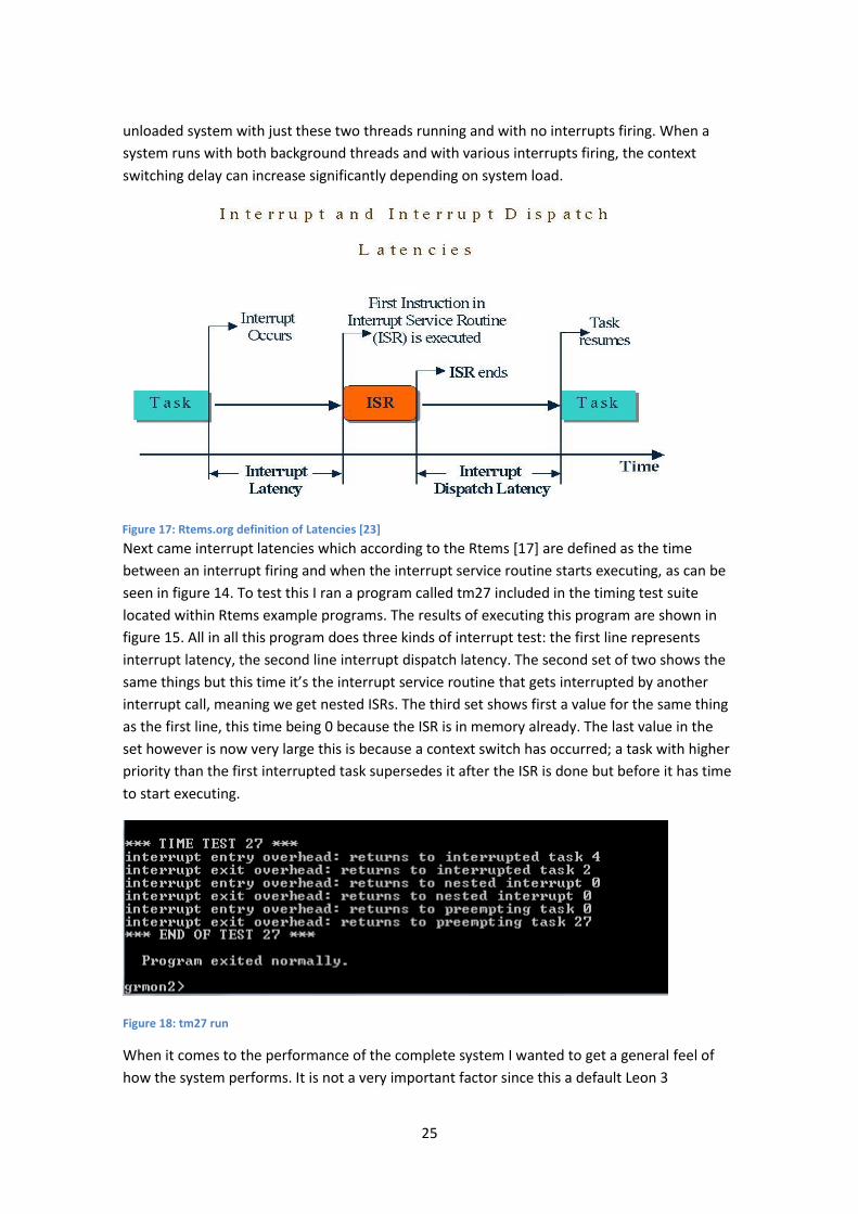
Next came interrupt latencies which according to the Rtems [17] are defined as the time
between an interrupt firing and when the interrupt service routine starts executing, as can be
seen in figure 14. To test this I ran a program called tm27 included in the timing test suite
located within Rtems example programs. The results of executing this program are shown in
figure 15. All in all this program does three kinds of interrupt test: the first line represents
interrupt latency, the second line interrupt dispatch latency. The second set of two shows the
same things but this time it’s the interrupt service routine that gets interrupted by another
interrupt call, meaning we get nested ISRs. The third set shows first a value for the same thing
as the first line, this time being 0 because the ISR is in memory already. The last value in the
set however is now very large this is because a context switch has occurred; a task with higher
priority than the first interrupted task supersedes it after the ISR is done but before it has time
to start executing.
Figure 18: tm27 run
When it comes to the performance of the complete system I wanted to get a general feel of
how the system performs. It is not a very important factor since this a default Leon 3
Figure 17: Rtems.org definition of Latencies [23]

26
configuration which is far from the “best” setup of the Leon 3 and performance wise many
improvements are available. Included in the Rtems package is an Nbench [18] port made for
Rtems, the results of its execution can be seen in figure 10. The program ran smoothly except
for the assignment problem which executed slowly which also shows in the results.
The final attribute to measure was how much space does the Rtems OS need? This will vary
depending on how much of the kernel is initialized and is of importance since a large
executable needs more realized memory on the FPGA, needs more overhead etc., the smaller
the better. Tables 1 show the sizes of various programs that have been used to benchmark
and verify the system. In essence this shows that the kernel is small. The netdemo program
includes most of the Rtems OS functionality but is still smaller than the benchmark which has
less of that but a lot more of its “own” code.
Rtems files sizes
CS 3400 KB
nbench 6012 KB
netdemo 4476 KB
tm27 3329 KB
spwltest 193 KB
spwamba 3504 KB
Table 1: Rtems executable sizes

27
5 Results
When this project started four goals were established by Omnisys instruments in terms of
what they wanted to learn from this thesis. All of these four goals have been achieved to
varying degrees. For the first goal a Leon 3 template design was synthesized and realised on
the Virtex-5 board and showed plenty of available space and all Leon 3 supporting RTOS was
looked at and evaluated and Rtems was chosen as the best candidate. The second goal was
achieved when, a Spacewire core was connected on the AHB bus to the template design and
the complete design was programmed into the Virtex-5 FPGA. This was verified using Grmon
which found the new core attached to the AHB bus. Third, An Rtems compilation environment
was installed and various programs compiled for the Leon 3 architecture. Using this compiler
several programs aimed at testing the functionality of the cores was compiled and ran on the
FPGA verifying that most of it was working. One of the software reported an error in the error
handling of the Spacewire link which has yet to be solved and Spacewire communication
between two systems has only been tested sparingly. Fourth and finally, benchmarking
software measured Rtems concerning switching latency, interrupt latencies and algorithmic
capabilities.
To put the benchmarking numbers into context you would want to compare them to their
competitors. This proved difficult mainly because the numbers you receive are so heavily
dependent on the system you run on and with most RTOS being very configurable it also
depends on how you implement it. In order to make a fair comparison you would need to run
the same test programs on those RTOS on the same hardware. Finding numbers on the various
competitors is easy; comparing them fairly is harder and outside the scope of this project.

28
6 Conclusion From the synthesis report the Virtex-5 can without trouble support a medium performance
Leon 3 design with this Spacewire core. The synthesis showed that 67% of the slices were used
and only 22% of the slice registers, meaning plenty to spare. Taxing programs such netdemo
and nbench can run on this system without incurring significant delay, although the
assignment algorithm of the nbench was slow. For this project this is a very good thing due to
the fact that the exact performance need of the final ICU is unknown. That means the
requirements on the hardware can go both ways which makes it important that sufficient
space is available. But can also mean that the Virtex-5 should be replaced by a smaller more
suitable FPGA.
Starting to work with Rtems without previous experience of developing RTOS/OS made me
realise this is a very broad subject and just trying to learn how one worked took a lot of time.
Setting up a development environment for just your system and knowing what configurations
to use took much reading with some trial and error.
The Rtems open source community is a font of knowledge, which also means it can be difficult
to navigate and hard to find exactly what you’re looking for. That aside Rtems is a good system
to work with, highly configurable, helpful community and easy to use.
6.1 Future works With the results so far with this project there are still a couple of things left to do, most
importantly on the error side but also from personal interest. The error that showed up in the
spwamba_test happens when the program initiates a transmit action from an invalid address
and needs more looking into. Next is testing more thoroughly with a real Spacewire connection
not just through a loopback cable. Although link layer contact was established the different
software programs couldn’t communicate. A real personal interest achievement would have
been to have the Rtems OS boot when the Leon 3 Core programs the FPGA.

29
Bibliography [1] STEAMR Omnisys, http://www.omnisys.se/products/microwave-and-radiometers/steamr
[2] STEAMR receiver chain, http://www.nrao.edu/meetings/isstt/proceed/2009-
Proceedings.pdf
[3] Xilinx ML507 development board, http://www.xilinx.com/products/boards-and-kits/HW-
V5-ML507-UNI-G.htm
[4] Aeroflex Gaisler GRLIB, http://www.gaisler.com/index.php/products/ipcores/soclibrary
[5] ARM AMBA v.2 specifications, http://www-micro.deis.unibo.it/~magagni/amba99.pdf
[6] Aeroflex Gaisler Leon 3 Processor,
http://www.gaisler.com/index.php/products/processors/leon3?task=view&id=13
[7] Leon 3 SPARC v8 Manual, http://www.gaisler.com/doc/sparcv8.pdf
[8] ESA Spacewire standard, http://spacewire.esa.int/content/Standard/Standard.php
[9] Aeroflex Gaisler GRLIB supported RTOS,
http://www.gaisler.com/doc/operating_systems_product_sheet.pdf
[10] ESA, http://www.esa.int/Our_Activities/Space_Engineering/LEON_s_first_flights
[11] Cygwin, http://www.cygwin.com/
[12] Aeroflex Gaisler Configuration and development guide,
http://www.gaisler.com/products/grlib/guide.pdf
[13] Rtems Ubuntu install guide,
http://wiki.rtems.org/wiki/index.php/Building_the_RTEMS_toolset_on_Ubuntu
[14] Rtems Building Tools guide, http://rtems.org/wiki/index.php/Building_Tools
[15] Qemu machine emulator, http://wiki.qemu.org/Main_Page
[16] Star-dundee USB brick, http://www.star-dundee.com/products/spacewire-usb-brick
[17] Rtems.org: interrupt latency, http://www.rtems.org/onlinedocs/releases/rtemsdocs-
4.6.6/share/rtems/html/supplements/powerpc/powerpc00059.html
[18] Nbench, http://www.tux.org/~mayer/linux/bmark.html
[19] Figure ML507 Virtex-5, http://www.xilinx.com/products/boards-and-kits/HW-V5-ML507-
UNI-G-image.htm
[20] Figure GRLIB archive structure,
http://www.rte.se/sites/default/files/Blog/Modesty/Modesty_5_2.png

30
[21] Figure Leon 3 template design, http://www.gaisler.com/products/grlib/grlib.pdf
[22] Figure Rtems automake structure, http://rtems.org/wiki/images/b/b8/Bootstrap.png
[23] Figure Rtems.org Latencies description,
http://physics.usask.ca/%7Eangie/ep414/notes/interrupt_latency.jpg

31
Appendix CS-u.c
/* * COPYRIGHT (c) 1989-2009. * On-Line Applications Research Corporation (OAR). * * The license and distribution terms for this file may be * found in the file LICENSE in this distribution or at * http://www.rtems.com/license/LICENSE. * * $Id: task1.c,v 1.18 2009/05/09 21:24:06 joel Exp $ */ #define CONFIGURE_INIT #include "system.h" #include "timesys.h" rtems_id Semaphore_id; rtems_task High_task(rtems_task_argument argument); rtems_task Low_task(rtems_task_argument argument); rtems_task Init(rtems_task_argument argument) { rtems_id task_id; rtems_status_code status; Print_Warning(); puts( "\n\n*** TIME TEST 25 ***" ); status = rtems_semaphore_create( rtems_build_name( 'S', 'M', '1', ' ') , 0, RTEMS_DEFAULT_ATTRIBUTES, RTEMS_NO_PRIORITY, &Semaphore_id ); directive_failed( status, "rtems_semaphore_create of SM1" ); status = rtems_task_create( rtems_build_name( 'L', 'O', 'W', ' ' ), 100, RTEMS_MINIMUM_STACK_SIZE, RTEMS_DEFAULT_MODES, RTEMS_DEFAULT_ATTRIBUTES, &task_id

32
); directive_failed( status, "rtems_task_create LOW" ); status = rtems_task_start( task_id, Low_task, 0 ); directive_failed( status, "rtems_task_start LOW" ); status = rtems_task_delete( RTEMS_SELF ); directive_failed( status, "rtems_task_delete of RTEMS_SELF" ); } rtems_task High_task(rtems_task_argument argument) { (void) rtems_semaphore_obtain(Semaphore_id,RTEMS_DEFAULT_OPTIONS,0xffffffff); end_time = benchmark_timer_read(); put_time("Time lapsed",end_time,1,0,CALLING_OVERHEAD_CLOCK_TICK); rtems_task_delete( RTEMS_SELF ); } rtems_task Low_task(rtems_task_argument argument) { rtems_status_code stat; uint32_t avg, x,y; rtems_id task_id; y = 100; x = 0; avg = 0; while ( x < y) { stat = rtems_task_create( rtems_build_name( 'T', 'I', 'M', 'E' ), 10, RTEMS_MINIMUM_STACK_SIZE, RTEMS_DEFAULT_MODES, RTEMS_DEFAULT_ATTRIBUTES, &task_id ); directive_failed( stat, "rtems_task_create LOOP" ); stat = rtems_task_start( task_id, High_task, 0 ); directive_failed( stat, "rtems_task_start LOOP" ); benchmark_timer_initialize(); (void) rtems_semaphore_release(Semaphore_id); avg = avg + end_time; x++; } put_time("Total Switching time in micro seconds",avg,1,0,CALLING_OVERHEAD_CLOCK_TICK);

33
put_time("Total Switches",y,1,0,CALLING_OVERHEAD_CLOCK_TICK); puts( "*** END OF TEST 25 ***" ); rtems_test_exit( 0 ); }