Embed Size (px)
Citation preview
Abstract— A design of an electroacoustic instrument
prototype for localization of a dominant noise source in the living and working environment is presented in this paper. Presented prototype is based on the conventional delay-and-sum beamforming algorithm which is implemented on an FPGA (Field Programmable Gate Array) platform. Sound signals are provided by a receiver system, based on a digital MEMS microphone array. The circular microphone array is oriented in a horizontal plane, enabling 360 degrees of acoustic viewing angle. Configuration enables the implementation of the beamforming algorithm in real time. Additionally, FPGA brings many benefits in terms of safety, reliability, rapidity, and power consumption. The system has been designed using rapid prototyping methodology with Matlab Simulink tools. A prototype was built, tested and used to validate numerical simulations. The prototype was also used for field measurements of heating plants in Novi Sad and Belgrade. Results of measurements were successfully applied in definition of sound sources and model, providing the best background for optimal noise mitigation measures.
Index Terms—microphone array, MEMS, beamforming, Matlab-Simulink, FPGA, noise control.
I. INTRODUCTION BEAMFORMING is a general signal processing technique
used to control directionality of the reception or transmission of a signal with an array of transducers [1]. Acoustic beamforming can be regarded as a spatial filter operation for the data received from a microphone/sensor array. It can be used to determine location and intensity of the sound source [1]-[7]. This technique of sound source localization has found a wide range of applications in many fields, from acoustic cameras, medical ultrasound devices, military applications, cataloguing wildlife in rural areas, videoconferencing, home surveillance, patient care, to localization of noise pollution sources in urban environments. Examples of military applications are localization of the sniper’s position in a counter-sniper system and localization of submarines using hydrophones [7], [8].
Dejan Todorović is with Dirigent Acoustics, Mažuranićeva 29, 11050 Belgrade, Serbia, (e-mail: [email protected]).
Iva Salom is with the Mihailo Pupin Institute, Volgina 15, 11060 Belgrade, Serbia; (e-mail: [email protected]).
Vladimir Čelebić is with the Mihailo Pupin Institute, Volgina 15, 11060 Belgrade, Serbia; (e-mail: [email protected]).
Jurij Prezelj is with the Faculty of mechanical engineering, University of Ljubljana, Aškerčeva 6, 1000 Ljubljana, Slovenia, (e-mail: [email protected]).
Since the most optimal solution assumes that data from all the microphones to be processed in parallel, the application of FPGA (Field Programmable Gate Array) technology arises as the best solution for the implementation of the beamforming algorithm on a single module, especially due to the possibility of adding new algorithms and improving the existing, [8]-[12]. Additionally, FPGAs are bringing many benefits in terms of safety, reliability, rapidity, and power consumption. Recently, digital MEMS (Micro Electro Mechanical) microphones have been introduced and are nowadays found in most cell-phones, digital cameras, Bluetooth headsets on the market. Their quality is continuously improving, and pre-amplifier, signal conditioning and analogue-to-digital conversion are often integrated on a single chip. This results in very compact and lightweight designs [12]. The major drawbacks using FPGA technology are high costs and need for integration of peripherals such as AD (analogue-to-digital) and DA (digital-to-analogue) converters. On the other hand, a digital MEMS microphone connects to an FPGA directly on the digital level, without converters.
The facts posed above induced an idea to design an acoustic system for localization of the dominant noise source by implementation of the conventional delay-and sum beamforming algorithm on FPGA platform with a sound receiver system based on digital MEMS microphones. The realization of the system, presented in the paper, included hardware and mechanics system design from the scratch, hardware and signal integrity verification using HypeLynks environment, algorithm simulations in Matlab, algorithm implementation design using rapid prototyping methodology with Matlab Simulink tools, and connection of all parts of the system in Xilinx ISE environment. Performance evaluation of the FPGA design is presented in terms of hardware resources for the chosen Xilinx Spartan- family. Comparison of the simulation results and the results obtained on real system is given, as well.
II. DELAY-AND-SUM BEAMFORMING ALGORITHM Beamforming is a method of spatial filtering which
differentiates desired signals from noise and interference based on their location. The simplest beamforming algorithm is the delay-and-sum beam former which works by compensating signal delay to each microphone appropriately before they are combined using an additive operation. The outcome of this delayed signal summation is reinforcement of the desired signal, i.e. the signal the signal coming from a desired direction (array focus) while suppressing signals coming from all other directions, and the noise in each
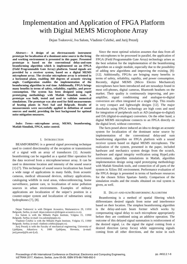
Implementation and Application of FPGA Platform with Digital MEMS Microphone Array
Dejan Todorović, Iva Salom, Vladimir Čelebić, and Jurij Prezelj
Proceedings of 4th International Conference on Electrical, Electronics and Computing Engineering, IcETRAN 2017, Kladovo, Serbia, June 05-08, ISBN 978-86-7466-692-0
pp. AKI2.2.1-6
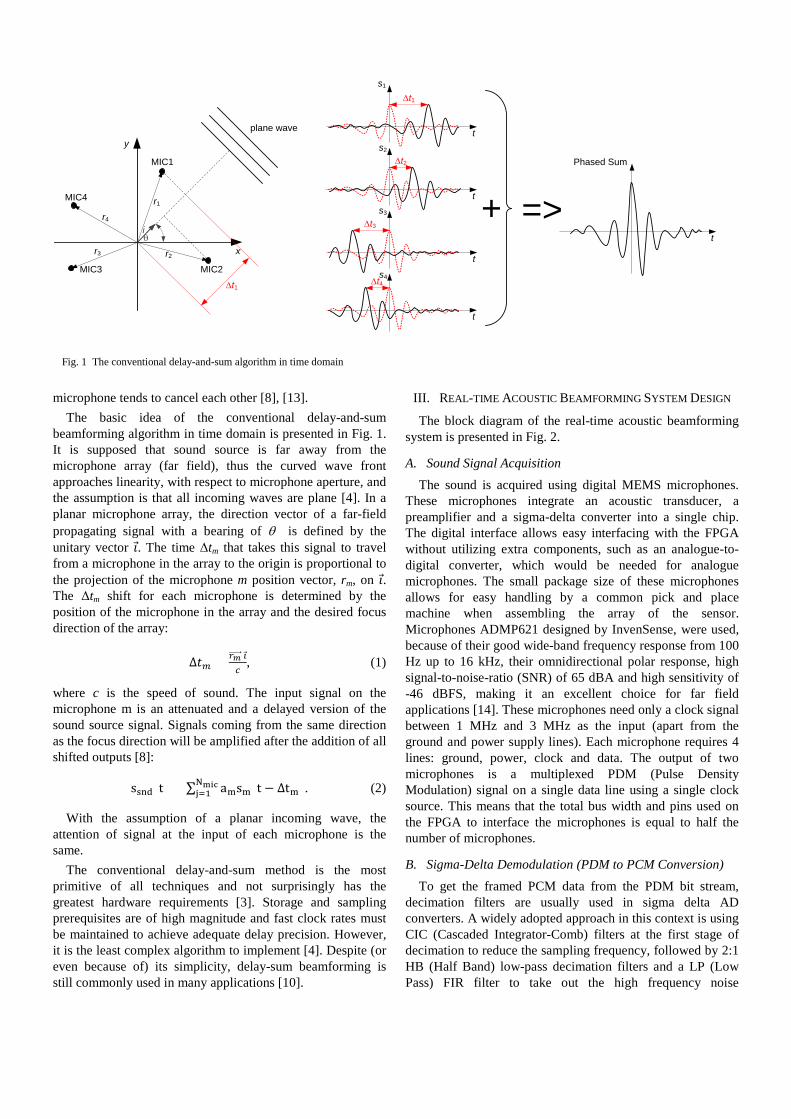
microphone tends to cancel each other [8], [13]. The basic idea of the conventional delay-and-sum
beamforming algorithm in time domain is presented in Fig. 1. It is supposed that sound source is far away from the microphone array (far field), thus the curved wave front approaches linearity, with respect to microphone aperture, and the assumption is that all incoming waves are plane [4]. In a planar microphone array, the direction vector of a far-field propagating signal with a bearing of θ is defined by the unitary vector 𝚤. The time Δtm that takes this signal to travel from a microphone in the array to the origin is proportional to the projection of the microphone m position vector, rm, on 𝚤. The Δtm shift for each microphone is determined by the position of the microphone in the array and the desired focus direction of the array:
Δ𝑡𝑚 = 𝑟𝑚�����⃗ 𝚤𝑐
, (1)
where c is the speed of sound. The input signal on the microphone m is an attenuated and a delayed version of the sound source signal. Signals coming from the same direction as the focus direction will be amplified after the addition of all shifted outputs [8]:
ssnd(t) = ∑ amsm(t − Δtm)Nmicj=1 . (2)
With the assumption of a planar incoming wave, the attention of signal at the input of each microphone is the same.
The conventional delay-and-sum method is the most primitive of all techniques and not surprisingly has the greatest hardware requirements [3]. Storage and sampling prerequisites are of high magnitude and fast clock rates must be maintained to achieve adequate delay precision. However, it is the least complex algorithm to implement [4]. Despite (or even because of) its simplicity, delay-sum beamforming is still commonly used in many applications [10].
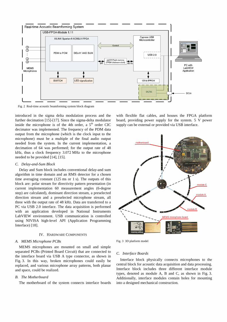
III. REAL-TIME ACOUSTIC BEAMFORMING SYSTEM DESIGN
The block diagram of the real-time acoustic beamforming system is presented in Fig. 2.
A. Sound Signal Acquisition The sound is acquired using digital MEMS microphones.
These microphones integrate an acoustic transducer, a preamplifier and a sigma-delta converter into a single chip. The digital interface allows easy interfacing with the FPGA without utilizing extra components, such as an analogue-to-digital converter, which would be needed for analogue microphones. The small package size of these microphones allows for easy handling by a common pick and place machine when assembling the array of the sensor. Microphones ADMP621 designed by InvenSense, were used, because of their good wide-band frequency response from 100 Hz up to 16 kHz, their omnidirectional polar response, high signal-to-noise-ratio (SNR) of 65 dBA and high sensitivity of -46 dBFS, making it an excellent choice for far field applications [14]. These microphones need only a clock signal between 1 MHz and 3 MHz as the input (apart from the ground and power supply lines). Each microphone requires 4 lines: ground, power, clock and data. The output of two microphones is a multiplexed PDM (Pulse Density Modulation) signal on a single data line using a single clock source. This means that the total bus width and pins used on the FPGA to interface the microphones is equal to half the number of microphones.
B. Sigma-Delta Demodulation (PDM to PCM Conversion) To get the framed PCM data from the PDM bit stream,
decimation filters are usually used in sigma delta AD converters. A widely adopted approach in this context is using CIC (Cascaded Integrator-Comb) filters at the first stage of decimation to reduce the sampling frequency, followed by 2:1 HB (Half Band) low-pass decimation filters and a LP (Low Pass) FIR filter to take out the high frequency noise
θi
r1
r2r3
r4
plane wave
MIC1
MIC2
MIC4
MIC3
x
y
t
t
t
t
∆t1
∆t1
∆t2
∆t3
∆t4
+t
=>
s1
Phased Sums2
s3
s4
Fig. 1 The conventional delay-and-sum algorithm in time domain
introduced in the sigma delta modulation process and the further decimation [15]-[17]. Since the sigma-delta modulator inside the microphone is of the 4th order, a 5th order CIC decimator was implemented. The frequency of the PDM data output from the microphone (which is the clock input to the microphone) must be a multiple of the final audio output needed from the system. In the current implementation, a decimation of 64 was performed; for the output rate of 48 kHz, thus a clock frequency 3.072 MHz to the microphone needed to be provided [14], [15].
C. Delay-and-Sum Block Delay and Sum block includes conventional delay-and sum
algorithm in time domain and an RMS detector for a chosen time averaging constant (125 ms or 1 s). The outputs of this block are: polar stream for directivity pattern presentation (in current implementation 60 measurement angles (6-degree step) are calculated), dominant direction stream, a preselected direction stream and a preselected microphone stream, all three with the output rate of 48 kHz. Data are transferred to a PC via USB 2.0 interface. The data acquisition is performed with an application developed in National Instruments LabVIEW environment. USB communication is controlled using NIVISA high-level API (Application Programming Interface) [18].
IV. HARDWARE COMPONENTS
A. MEMS Microphone PCBs MEMS microphones are mounted on small and simple
separated PCBs (Printed Board Circuit) that are connected to the interface board via USB A type connector, as shown in Fig. 3. In this way, broken microphones could easily be replaced, and various microphone array patterns, both planar and space, could be realized.
B. The Motherboard The motherboard of the system connects interface boards
with flexible flat cables, and houses the FPGA platform board, providing power supply for the system. 5 V power supply can be external or provided via USB interface.
Fig. 3 3D platform model
C. Interface Boards Interface block physically connects microphones to the
central block for acoustic data acquisition and data processing. Interface block includes three different interface module types, denoted as module A, B and C, as shown in Fig. 3. Additionally, interface modules contain holes for mounting into a designed mechanical construction.
Fig. 2 Real-time acoustic beamforming system block diagram

D. FPGA Platform Board For the realization of the main functions of the system a
USB-FPGA module was chosen, because of its compactness, price, and the number of differential parts that were brought out to its general-purpose I/O connectors. The module contains a Xilinx Spartan-6 LX25 FPGA and a USB 2.0 Cypress microcontroller for interfacing to a PC. The module is simply plugged into the motherboard of the system thus quick start of the developed VHDL firmware debugging was enabled. This provided a considerable time savings since the effort to incorporate a complicated Spartan-6 LX25 on the motherboard would not have been insignificant. The interface chip for USB 2.0 communication was integrated on the module, with software for performing USB transfer between a data acquisition PC, running LabVIEW, and the XILINX Spartan-6. The USB-FPGA module placed on the motherboard is shown in Fig. 4. The approximate FPGA resource analysis on XILINX Spartan-6 XCS6LX25 is given in Table I.
Fig. 4 USB-FPGA module on the motherboard
TABLE I FPGA RESOURCE ANALYSIS ON XILINX SPARTAN-6 XCS6LX25
Available Implementation
Slices 3758 app. 84% Block RAM 52 app. 63% DSP48A1s 38 app. 71%
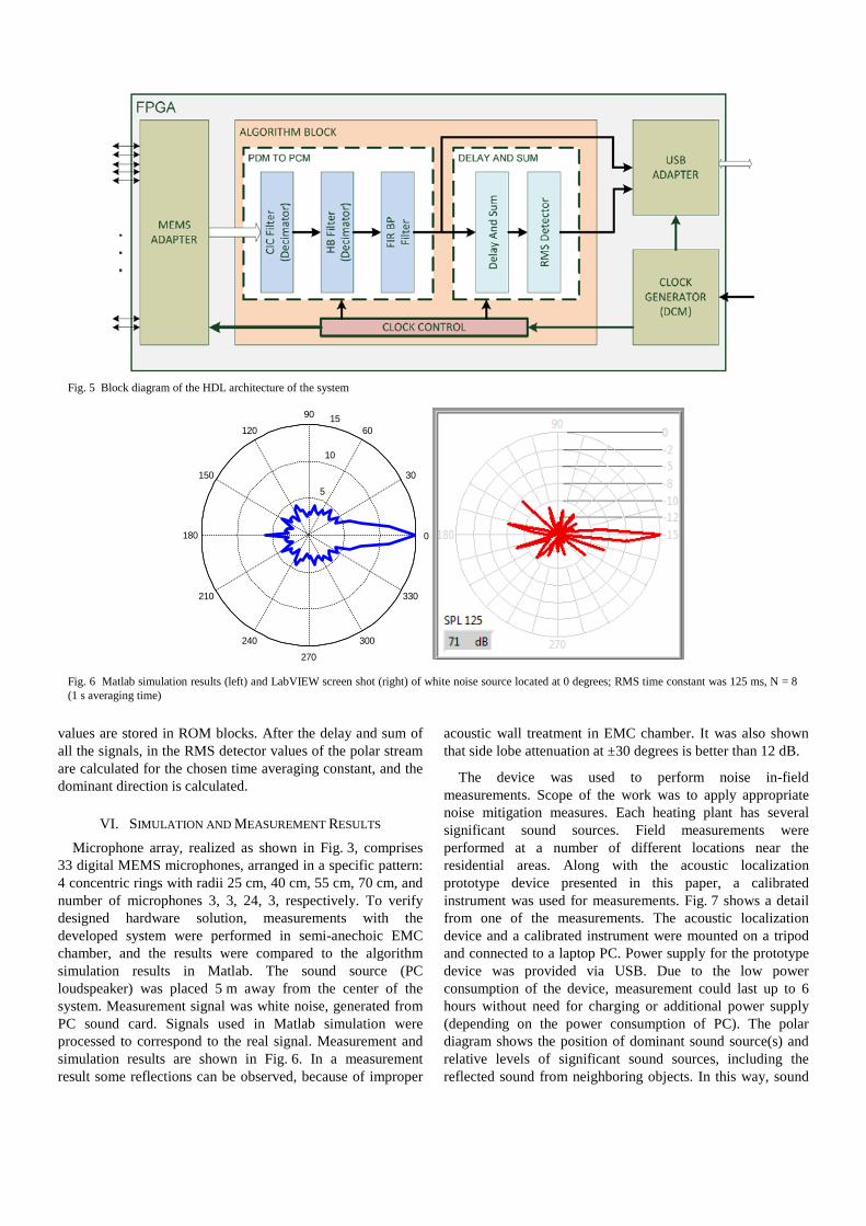
V. HDL ARCHITECTURE AND IMPLEMENTATION RESULTS FPGA systems are usually designed using hardware
description languages (HDLs) such as VHDL or Verilog in Xilinx ISE environment. On the other hand, when Model-Based Design is used to target FPGAs, systems can be designed and simulated with MATLAB and Simulink, and then bit-true cycle-accurate synthesizable VHDL (or Verilog)
code can be generated using Simulink HDL Coder within the Xilinx addition for the Simulink – System Generator. Sometimes there is a benefit from mixture approaches and such approach is chosen in this design. Block diagram is shown on Fig. 5. The design consists of the following blocks: 1-Algorithm block, 2-Clock generator, 3- MEMS adapter, 4-USB adapter. All the blocks, except the algorithm block were implemented as VHDL components, while the algorithm block was built as a model in Simulink.
A. XILINX ISE VHDL Environment The Xilinx ISE software controls all aspects of the design
flow. Through the Project Navigator interface, one can access of the design entry and design implementation tools. All components realized with VHDL or translated Simulink model are synthetized, translated, placed and routed under ISE.
Clock generator synthesize main (system) clock from the incoming clock sourced by USB controller. The clock generator is realized with Digital Clock Managers (DCMs). DCMs provide advanced clocking capabilities to Spartan-6 FPGA applications. DCMs optionally multiply or divide the incoming clock frequency to synthesize a new clock frequency. DCMs also eliminate clock skew, thereby improving system performance. Similarly, a DCM optionally phase shifts the clock output to delay the incoming clock by a fraction of the clock period. The DCMs integrate directly with the FPGA’s global low skew clock distribution network. MEMS adapter provides all clock signals to MEMS microphones and performs PDM signal acquisition. PDM signal is passed to the algorithm block. USB adapter collects all calculated data from the algorithm block, format data adding header and check sum and sends formatted data to the USB controller. It receives control messages sent from the user application on the PC, as well.
B. Development in the Matlab-Simulink Environment The FPGA design of the system was developed in Simulink
System Generator. System Generator enables use of predefined elements (primitives) of the elementary logical and arithmetical circuits [19],[20]. The design is formed as block diagram with interconnections, as it is usually done in the Simulink. Signals are separated from basic Simulink environment, with special elements (input and output ports), so that the design for FPGA is a separate entity. Most of the system signal processing is realized in a single component in Simulink - the algorithm block. This block includes two smaller blocks: PDM to PCM block and Delay and Sum block.
PDM to PCM block converts input 1-bit PDM signals at 3072 kHz rate to 48 kHz PCM 16-bit signal. PDM to PCM conversion consists of three parts: a CIC decimation filter (realized using Xilinx CIC compiler 2.0) followed by two 2:1 HB filters and a LP FIR filter (all three realized using Xilinx FIR compiler 6.2).
Delay and Sum block first performs delay function of all input PCM signals using Dual Port RAM blocks. Delay table
values are stored in ROM blocks. After the delay and sum of all the signals, in the RMS detector values of the polar stream are calculated for the chosen time averaging constant, and the dominant direction is calculated.
VI. SIMULATION AND MEASUREMENT RESULTS
Microphone array, realized as shown in Fig. 3, comprises 33 digital MEMS microphones, arranged in a specific pattern: 4 concentric rings with radii 25 cm, 40 cm, 55 cm, 70 cm, and number of microphones 3, 3, 24, 3, respectively. To verify designed hardware solution, measurements with the developed system were performed in semi-anechoic EMC chamber, and the results were compared to the algorithm simulation results in Matlab. The sound source (PC loudspeaker) was placed 5 m away from the center of the system. Measurement signal was white noise, generated from PC sound card. Signals used in Matlab simulation were processed to correspond to the real signal. Measurement and simulation results are shown in Fig. 6. In a measurement result some reflections can be observed, because of improper
acoustic wall treatment in EMC chamber. It was also shown that side lobe attenuation at ±30 degrees is better than 12 dB.
The device was used to perform noise in-field measurements. Scope of the work was to apply appropriate noise mitigation measures. Each heating plant has several significant sound sources. Field measurements were performed at a number of different locations near the residential areas. Along with the acoustic localization prototype device presented in this paper, a calibrated instrument was used for measurements. Fig. 7 shows a detail from one of the measurements. The acoustic localization device and a calibrated instrument were mounted on a tripod and connected to a laptop PC. Power supply for the prototype device was provided via USB. Due to the low power consumption of the device, measurement could last up to 6 hours without need for charging or additional power supply (depending on the power consumption of PC). The polar diagram shows the position of dominant sound source(s) and relative levels of significant sound sources, including the reflected sound from neighboring objects. In this way, sound
Fig. 5 Block diagram of the HDL architecture of the system
Fig. 6 Matlab simulation results (left) and LabVIEW screen shot (right) of white noise source located at 0 degrees; RMS time constant was 125 ms, N = 8 (1 s averaging time)
5
10
15
30
210
60
240
90
270
120
300
150
330
180 0
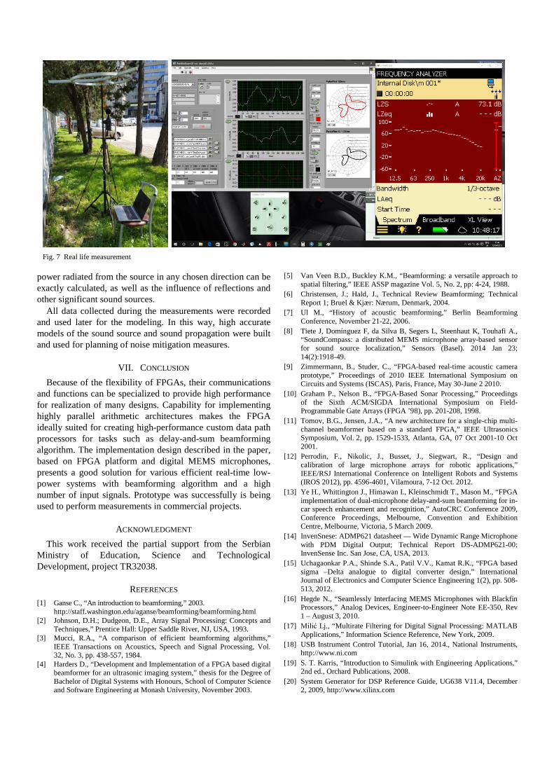
power radiated from the source in any chosen direction can be exactly calculated, as well as the influence of reflections and other significant sound sources.
All data collected during the measurements were recorded and used later for the modeling. In this way, high accurate models of the sound source and sound propagation were built and used for planning of noise mitigation measures.
VII. CONCLUSION Because of the flexibility of FPGAs, their communications
and functions can be specialized to provide high performance for realization of many designs. Capability for implementing highly parallel arithmetic architectures makes the FPGA ideally suited for creating high-performance custom data path processors for tasks such as delay-and-sum beamforming algorithm. The implementation design described in the paper, based on FPGA platform and digital MEMS microphones, presents a good solution for various efficient real-time low-power systems with beamforming algorithm and a high number of input signals. Prototype was successfully is being used to perform measurements in commercial projects.
ACKNOWLEDGMENT This work received the partial support from the Serbian
Ministry of Education, Science and Technological Development, project TR32038.
REFERENCES [1] Ganse C., “An introduction to beamforming,” 2003.
http://staff.washington.edu/aganse/beamforming/beamforming.html [2] Johnson, D.H.; Dudgeon, D.E., Array Signal Processing: Concepts and
Techniques,” Prentice Hall: Upper Saddle River, NJ, USA, 1993. [3] Mucci, R.A., “A comparison of efficient beamforming algorithms,”
IEEE Transactions on Acoustics, Speech and Signal Processing, Vol. 32, No. 3, pp. 438-557, 1984.
[4] Harders D., “Development and Implementation of a FPGA based digital beamformer for an ultrasonic imaging system,” thesis for the Degree of Bachelor of Digital Systems with Honours, School of Computer Science and Software Engineering at Monash University, November 2003.
[5] Van Veen B.D., Buckley K.M., “Beamforming: a versatile approach to spatial filtering,” IEEE ASSP magazine Vol. 5, No. 2, pp: 4-24, 1988.
[6] Christensen, J.; Hald, J., Technical Review Beamforming; Technical Report 1; Bruel & Kjær: Nærum, Denmark, 2004.
[7] Ul M., “History of acoustic beamforming,” Berlin Beamforming Conference, November 21-22, 2006.
[8] Tiete J, Domínguez F, da Silva B, Segers L, Steenhaut K, Touhafi A., “SoundCompass: a distributed MEMS microphone array-based sensor for sound source localization,” Sensors (Basel). 2014 Jan 23; 14(2):1918-49.
[9] Zimmermann, B., Studer, C., “FPGA-based real-time acoustic camera prototype,” Proceedings of 2010 IEEE International Symposium on Circuits and Systems (ISCAS), Paris, France, May 30-June 2 2010.
[10] Graham P., Nelson B., “FPGA-Based Sonar Processing,” Proceedings of the Sixth ACM/SIGDA International Symposium on Field-Programmable Gate Arrays (FPGA ’98), pp. 201-208, 1998.
[11] Tomov, B.G., Jensen, J.A., “A new architecture for a single-chip multi-channel beamformer based on a standard FPGA,” IEEE Ultrasonics Symposium, Vol. 2, pp. 1529-1533, Atlanta, GA, 07 Oct 2001-10 Oct 2001.
[12] Perrodin, F., Nikolic, J., Busset, J., Siegwart, R., “Design and calibration of large microphone arrays for robotic applications,” IEEE/RSJ International Conference on Intelligent Robots and Systems (IROS 2012), pp. 4596-4601, Vilamoura, 7-12 Oct. 2012.
[13] Ye H., Whittington J., Himawan I., Kleinschmidt T., Mason M., “FPGA implementation of dual-microphone delay-and-sum beamforming for in-car speech enhancement and recognition,” AutoCRC Conference 2009, Conference Proceedings, Melbourne, Convention and Exhibition Centre, Melbourne, Victoria, 5 March 2009.
[14] InvenSnese: ADMP621 datasheet — Wide Dynamic Range Microphone with PDM Digital Output; Technical Report DS-ADMP621-00; InvenSense Inc. San Jose, CA, USA, 2013.
[15] Uchagaonkar P.A., Shinde S.A., Patil V.V., Kamat R.K., “FPGA based sigma –Delta analogue to digital converter design,” International Journal of Electronics and Computer Science Engineering 1(2), pp. 508-513, 2012.
[16] Hegde N., “Seamlessly Interfacing MEMS Microphones with Blackfin Processors,” Analog Devices, Engineer-to-Engineer Note EE-350, Rev 1 – August 3, 2010.
[17] Milić Lj., “Multirate Filtering for Digital Signal Processing: MATLAB Applications,” Information Science Reference, New York, 2009.
[18] USB Instrument Control Tutorial, Jan 16, 2014., National Instruments, http://www.ni.com
[19] S. T. Karris, “Introduction to Simulink with Engineering Applications,” 2nd ed., Orchard Publications, 2008.
[20] System Generator for DSP Reference Guide, UG638 V11.4, December 2, 2009, http://www.xilinx.com
Fig. 7 Real life measurement