Embed Size (px)
Citation preview
I
Mälardalen University Press Licentiate Theses No. 106
IMPACT WAVE PROCESS MODELING AND OPTIMIZATION IN HIGH ENERGY RATE EXPLOSIVE WELDING
APPLIED MECHANICMohammad Tabatabaee Ghomi
2009
School of Sustainable Development of Society and Technology

II
Copyright © Mohammad Tabatabaee Ghomi, 2009 ISSN 1651-9256 ISBN 978-91-86135-35-5 Printed by Mälardalen University, Västerås, Sweden
II
Copyright © Mohammad Tabatabaee Ghomi, 2009 ISSN 1651-9256 ISBN 978-91-86135-35-5 Printed by Mälardalen University, Västerås, Sweden
3
Abstract Impact waves are used in many different industries and are classified according to whether they cause plastic or elastic deformations. In the plastic deformation mode, these waves can be used to produce special electrical joints. In the elastic deformation mode, they can be used to detect leakage or to measure the thickness of pipes. Both modes have applications in offshore technology. In this thesis the application of impact waves in the plastic deformation mode and explosive welding are discussed. In the explosive welding (EXW) process a high velocity oblique impact produced by a carefully controlled explosion occurs between two or more metals. The high velocity impact causes the metals to behave like fluids temporarily and weld together. This process occurs in a short time with a high rate of energy. EXW is a well known method for joining different metals together. It is a multidisciplinary research area and covers a wide range of science and technology areas including wave theory, fluid dynamics, materials science, manufacturing and modeling. Many of the important results in EXW research are obtained from experimentation. This thesis is mainly based on experimental work. However, it begins with a review of the fundamental theory and mechanisms of explosive welding and the different steps of a successful welding operation. Many different EXW tests are done on horizontal and vertical surfaces with unequal surface areas, and on curved surfaces and pipes. The remainder of the thesis evaluates the results of these experiments, measures the main parameters, and shows the results of simulations to verify the experimental results. The thesis ends with a number of suggestions for improving and optimizing the EXW process. One of these improvements is a model for joining metallic plates with unequal surface areas. An Al-Cu joint based on this model is used in the ALMAHDI aluminum factory, a large company in southern Iran that produces more than 200,000 tons of aluminum per year. Improved methods are also suggested for joining curved surfaces. These methods may have extensive applications in pipelines in oil and gas industries, especially in underwater pipes.

4

4
5
Sammanfattning Impact vågor används i många olika branscher och klassificeras beroende på om de orsakar plast eller elastiska deformationer. I plastisk deformation läge, kan dessa vågor användas för att tillverka speciella elektriska skarvar. I elastisk deformation läge, kan de användas för att upptäcka läckage eller att mäta tjockleken på rören. Båda lägena har tillämpningar inom offshore-teknik. I denna avhandling tillämpningen av effekten vågor i plastisk deformation mode och explosiva svetsning diskuteras. I den explosiva svetsning (EXW) behandla en hög hastighet sned anslaget av en noggrant kontrollerad explosion inträffar mellan två eller fler metaller. Den höga hastigheten effekten gör att metaller att bete sig som vätskor tillfälligt och svetsa ihop. Detta sker under en kort tid med hög energi. EXW är en välkänd metod för att gå olika metaller tillsammans. Det är ett tvärvetenskapligt forskningsområde och täcker ett brett spektrum av vetenskapliga och tekniska områden inklusive vågrörelselära, strömningsmekanik, materialvetenskap, tillverkning och modellering. Många av de viktigaste resultaten i EXW forskningen erhålls från experiment. Denna avhandling är huvudsakligen baserad på experimentellt arbete. Däremot börjar det med en genomgång av grundläggande teori och mekanismer av explosiv svetsning och de olika stegen i en lyckad svetsning operation. Många olika EXW tester görs på horisontella och vertikala ytor med ojämn yta, och på krökta ytor och rörledningar. Återstoden av avhandlingen utvärderar resultaten av dessa försök, åtgärder viktiga parametrar och visar resultaten av simuleringar för att verifiera de experimentella resultaten. Avhandlingen avslutas med ett antal förslag för att förbättra och optimera EXW processen. En av dessa förbättringar är en modell för att gå metallplattor med ojämna ytor. En Al-Cu gemensamt baserade på denna modell används i ALMAHDI aluminium fabriken, ett stort företag i södra Iran som producerar mer än 200.000 ton aluminium per år. Förbättrade metoder föreslås också för att gå med krökta ytor. Dessa metoder kan ha många olika tillämpningar i rörledningar i olje-och gasindustrin, särskilt i vattnet rör.
6
Acknowledgements The work described in this thesis was carried out at the School of Sustainable Development of Society and Technology, Mälardalen University, Sweden. I would like to thank my supervisor, Professor Jafar Mahmoudi for his encouragement, guidance, scientific help and unlimited support. I would like to express my gratitude to Professor Erik Dahlquist and Professor Jinyue Yan. I would like to express my gratitude to Professor Gholamhossein Liaghat from Tarbiat Modares University, Professor Mohammad Mahjoob from Tehran University and Professor A. Darvizeh from Gilan University in Iran for their scientific help. I would like to express my gratitude to Dr. Adel Karim at Mälardalen University. The author would like to acknowledge Professor Dobroshin from PATON institute in Ukraine, Mr. Chavideh from Chime-Tec Company in Germany, ACECR, and the TDI organization in Iran for help with experiments.
7
List of Publications This thesis is based on the following papers and technical reports:
Appended Papers: Paper 1: Mohammad Tabatabaee, Jafar Mahmoudi and Gholamhossein Liaghat, An Applied Method for welding Metals of Unequal Surface Area Using Explosive Energy, Submitted to International Journal of Impact Engineering, ISSN: 0734-743X Paper2: Mohammad Tabatabaee, Jafar Mahmoudi and Gholamhossein Liaghat, Removing Leakage from oil and gas low pressure Pipes and vessels by high energy explosive welding method, Scientific Conference on “Energy systems with IT” in connection with the Energiting 2009, March 11-12 at Älvsjö fair, Stockholm, ISBN number 978-91-977493-4-3. Paper3: Mohammad Tabatabaee, Jafar Mahmoudi and Gholamhossein Liaghat, Effect of Explosive Layer thickness on detonation velocity in a high energy process, Submitted to High Energy Physics Journal, ISSN: 1126-6708. Report Mohammad Tabatabaee, Impact wave process control in explosive welding application, Technical report No. 3, 20 July 2008, Mälardalen University
Papers not appended: Paper 4: Mohammad Tabatabaee and Jafar Mahmoudi, Finite element simulation of explosive welding, The 49th Scandinavian Conference on Simulation and Modeling (SIMS2008), ISBN-13: 978-82-579-46326 Paper 5: Mohammad Tabatabaee and Jafar Mahmoudi, FEM method simulation for Aluminum - Iron - Copper bonding using explosive welding method, IASTED International Conference on Applied Simulation and Modeling, June 25, 2008, at Corfu, Greece. (ASM 2008), ISBN- 978-0-88986-748-2 Paper 6: Mohammad Tabatabaee and Jafar Mahmoudi, An advanced method for Aluminum - Iron - Copper bonding using explosive welding method, SSSEC2008 conference, Stockholm, March 12-13, 2008 ISBN-978-91-977493-2-9 Paper 7: Mohammad Tabatabaee and Jafar Mahmoudi, An advanced method of explosive welding simulation, The 16th Annual (International) Conference on Mechanical Engineering, ISME2008, May 14-16, 2008, Shahid Bahonar University of Kerman, Iran
8
Nomenclature and abbreviations Latin letters P pressure VD, Vd detonation velocity Vp, Vf velocity of flyer plate Vc, Vw collision velocity Ei strain energy Re Reynolds number E Young’s modulus C speed of sound H hardness A amplitude T temperature T thickness Greek letters α initial angle β dynamic angle λ wave length σ tensile stress ρ density Abbreviations EXW explosive welding BSEW bond strength explosive welded WW welding window SEM scanning electron microscope UTS ultimate tensile stress
9
Table of Contents
Abstract ........................................................................................................................................... 3Sammanfattning .............................................................................................................................. 5Acknowledgements ......................................................................................................................... 6List of Publications ......................................................................................................................... 7Nomenclature and abbreviations ..................................................................................................... 8List of Figures ............................................................................................................................... 10List of Tables ................................................................................................................................ 111. Introduction ......................................................................................................................... 13
1.1. Background ................................................................................................................................. 13
1.2. Literature review ........................................................................................................................ 13
1.3. Motivation and objective ............................................................................................................ 14
1.4. Research approach ...................................................................................................................... 14
1.5. Limitations .................................................................................................................................. 15
1.6. Methodology ............................................................................................................................... 15
1.7. Thesis Outline ............................................................................................................................. 16
2. Theory ................................................................................................................................... 172.1. Mechanism and set up ................................................................................................................ 17
2.2. The impact wave in explosive welding ...................................................................................... 18
2.3. Predicting the wavelength .......................................................................................................... 19
2.4. Bonding criteria .......................................................................................................................... 20
2.5. Welding window ........................................................................................................................ 21
2.6. Governing equations ................................................................................................................... 24
2.7. Testing methods .......................................................................................................................... 24
2.8. Simulation of the explosive welding process ............................................................................. 27
3. Experimental Data, Results and Calculations ....................................................................... 293.1. Experiment setup ........................................................................................................................ 29
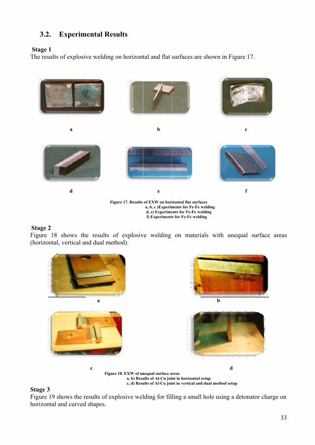
3.2. Experimental Results .................................................................................................................. 33
3.3. Calculation, numerical and simulation results ............................................................................ 35
3.4. Test Results ................................................................................................................................ 40
4. Discussion and future work .................................................................................................. 454.1. Discussion ................................................................................................................................... 45
4.2. Future work ................................................................................................................................ 47
5. Conclusions ........................................................................................................................... 495.1. Concluding remarks .................................................................................................................... 49
5.2. Practical Output .......................................................................................................................... 50
6. References ............................................................................................................................. 537. Papers summary .................................................................................................................... 55
10
List of Figures Figure 1. a) Basic set up for explosive welding [1] b) The explosive bonding process [4] ....... 17Figure 2: Geometry of the process during the collapse [1] ............................................................... 17Figure 3. Impact wave reflection [ 1] ................................................................................................. 19Figure 4. Shape of the wave at the interface of the plates [ 1] ........................................................... 19Figure 5. An example of a WW diagram in the Vc-β plane .............................................................. 22Figure 6. Determination of detonation velocity by Dutrich method [ 4] ........................................... 25Figure 7. The chisel test [ 1]. ............................................................................................................. 26Figure 8. Pressure simulation by AUTODYN software [ 34] ............................................................ 27Figure 9. Setup for Fe-Fe welding ..................................................................................................... 29Figure 10. Unequal surface area set up ............................................................................................. 30Figure 11. Al-Cu vertical unequal surface area and dual method set up ........................................... 31Figure 12. Set up for filling a small hole .......................................................................................... 31Figure 13. Set up for welding on a curve .......................................................................................... 31Figure 14. Set up for repairing a leak and filling a small hole in a pipe ........................................... 32Figure 15. Dutrich method setup using a thin Aluminum plate ........................................................ 32Figure 16. Dutrich method setup using a Brass plate ....................................................................... 32Figure 17. Results of EXW on horizontal flat surfaces ..................................................................... 33Figure 18. EXW of unequal surface areas ......................................................................................... 33Figure 19. EXW tests for filling a hole .............................................................................................. 34Figure 20. EXW with a detonator on a pipe for filling a small hole .................................................. 34Figure 21. Dutrich method test results ............................................................................................... 34Figure 22. WW for Cu-Fe joint .......................................................................................................... 36Figure 23. Welding window for Fe-Fe joint ...................................................................................... 37Figure 24. WW for Al-Cu joint .......................................................................................................... 39Figure 25. Effect of explosive material thickness on detonation velocity ......................................... 41Figure 26. Effect of explosive material thickness on detonation velocity in general ........................ 41Figure 27. Chisel test for 2 types of weld .......................................................................................... 41Figure 28. BSEW in width direction .................................................................................................. 42Figure 29. BSEW in length direction ................................................................................................. 42Figure 30. Metallographic results ...................................................................................................... 43Figure 31. Results of simulation ........................................................................................................ 44Figure 32. Bonded areas measured by ultrasonic test for Al-Cu joint ............................................... 46Figure 33. A set up for filling a hole before welding ......................................................................... 50Figure 34. Al–Cu joints transmit the electric power of anode rods in the aluminum factory ............ 51
11
List of Tables Table 1. Summary of papers ............................................................................................................. 15Table 2. Specification of Fe-Fe horizontal setup ............................................................................... 29Table 3. Specification of Al-Cu horizontal setup .............................................................................. 29Table 4. Specification of Fe-Cu horizontal setup ............................................................................. 29Table 5. Specification of Al-Cu, unequal surface area, horizontal set up .......................................... 30Table 6. Specification of Al-Cu Vertical unequal surface area and dual method set up ................... 30Table 7. Specification of Stage 3 experiments ................................................................................... 31Table 8. Specification of experiments in Stage 4 ............................................................................... 31Table 9. Specification of experiments in Stage 5 (Dutrich method) .................................................. 32Table 10. Result of experiments described in Table 9 ....................................................................... 34Table 11. Calculation for line (a-a) .................................................................................................... 35Table 12. Calculation for line (f-f) ..................................................................................................... 35Table 13. Calculation for line (g-g) ................................................................................................... 36Table 14. Calculation for line (a-a) .................................................................................................... 36Table 15. Calculation for line (f-f) ..................................................................................................... 37Table 16. Calculation for line (g-g) ................................................................................................... 37Table 17. Calculation for line (a-a) .................................................................................................... 38Table 18. Calculation for line (f-f) ..................................................................................................... 38Table 19. Calculation for line (g-g) ................................................................................................... 38Table 20. Calculation of VD for different thicknesses of explosive material .................................... 40Table 21. Results of testing on measuring detonation velocity for different kinds of explosive materials ............................................................................................................................................. 40Table 22. Results of mechanical test in width direction .................................................................... 42Table 23. Results of mechanical test in length direction ................................................................... 42

12
12
13
1. Introduction
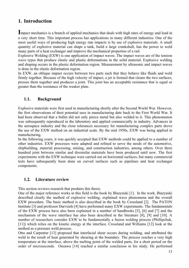
Impact mechanics is a branch of applied mechanics that deals with high rates of energy and load in a very short time. This important process has applications in many different industries. One of the most useful ways of producing high energy rate impacts is by use of explosive materials. A small quantity of explosive material can shape a tank, build a large crankshaft, has the power to weld many parts of a heat exchanger and improve the mechanical properties of a rail. Explosive Welding (EXW) is one application of impact waves. The impact waves are of the tension wave types that produce elastic and plastic deformations in the solid material. Explosive welding and shaping occurs in the plastic deformation region. Measurement by ultrasonic and impact waves is done in the elastic deformation region. In EXW, an oblique impact occurs between two parts such that they behave like fluids and weld firmly together. Because of the high velocity of impact, a jet is formed that cleans the two surfaces, presses them together and produces a joint. This joint has an acceptable resistance that is equal or greater than the resistance of the weaker plate.
1.1. Background
Explosive materials were first used in manufacturing shortly after the Second World War. However, the first observations of their potential uses in manufacturing date back to the First World War. It had been observed that a bullet did not only pierce metal but also welded to it. This phenomenon was subsequently reproduced in the laboratory and applied commercially in industry. Advances in the aerospace industry and the close tolerances necessary for manufacturing complex parts drove the use of the EXW method on an industrial scale. By the mid 1950s, EXW was being applied in manufacturing. In the following years, it was quickly accepted that EXW methods could be applied to a number of other industries. EXW processes were adapted and refined to serve the needs of the automotive, shipbuilding, material processing, mining, and construction industries, among others. Over three hundred joint between similar and dissimilar materials have been produced until now. The first experiments with the EXW technique were carried out on horizontal surfaces, but many commercial tests have subsequently been done on curved surfaces such as pipelines and heat exchanger components.
1.2. Literature review
This section reviews research that predates this thesis. One of the major reference works in this field is the book by Blazynski [1]. In the work, Blazynski described clearly the method of explosive welding, explained wave phenomena and the overall EXW procedure. The basic method is also described in the book by Crossland [2]. The PATON Institute [3] and professor Darvizeh [4] have performed many EXW experiments. The fundamentals of the EXW process have also been explained in a number of handbooks [5], [6] and [7] and the mechanism of the wave interface has also been described in the literature [8], [9] and [10]. A number of researchers consider EXW to be fundamentally a fusion welding process (Phillipchuk, [11]) which relies on the kinetic energy at the interface. Crossland and Williams [12] look at the method as a pressure weld process. Otto and Carpenter [13] proposed that interfacial shear occurs during welding, and attributed the weld to the result of heat generated by shearing at the boundary. The process reaches a very high temperature at the interface, above the melting point of the welded parts, for a short period on the order of microseconds. Onzawa [14] reached a similar conclusion in his study. He performed
14
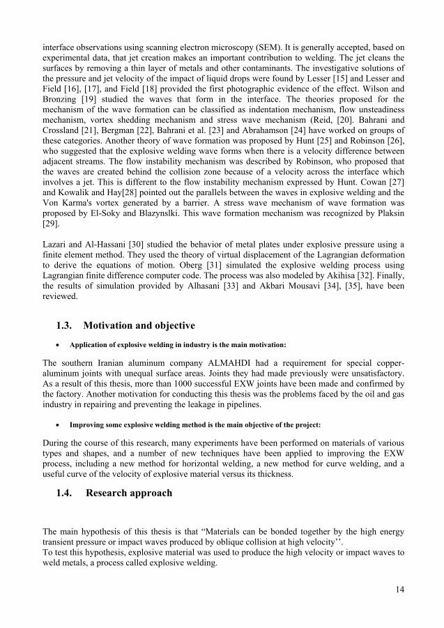
interface observations using scanning electron microscopy (SEM). It is generally accepted, based on experimental data, that jet creation makes an important contribution to welding. The jet cleans the surfaces by removing a thin layer of metals and other contaminants. The investigative solutions of the pressure and jet velocity of the impact of liquid drops were found by Lesser [15] and Lesser and Field [16], [17], and Field [18] provided the first photographic evidence of the effect. Wilson and Bronzing [19] studied the waves that form in the interface. The theories proposed for the mechanism of the wave formation can be classified as indentation mechanism, flow unsteadiness mechanism, vortex shedding mechanism and stress wave mechanism (Reid, [20]. Bahrani and Crossland [21], Bergman [22], Bahrani et al. [23] and Abrahamson [24] have worked on groups of these categories. Another theory of wave formation was proposed by Hunt [25] and Robinson [26], who suggested that the explosive welding wave forms when there is a velocity difference between adjacent streams. The flow instability mechanism was described by Robinson, who proposed that the waves are created behind the collision zone because of a velocity across the interface which involves a jet. This is different to the flow instability mechanism expressed by Hunt. Cowan [27] and Kowalik and Hay[28] pointed out the parallels between the waves in explosive welding and the Von Karma's vortex generated by a barrier. A stress wave mechanism of wave formation was proposed by El-Soky and Blazynslki. This wave formation mechanism was recognized by Plaksin [29].
Lazari and Al-Hassani [30] studied the behavior of metal plates under explosive pressure using a finite element method. They used the theory of virtual displacement of the Lagrangian deformation to derive the equations of motion. Oberg [31] simulated the explosive welding process using Lagrangian finite difference computer code. The process was also modeled by Akihisa [32]. Finally, the results of simulation provided by Alhasani [33] and Akbari Mousavi [34], [35], have been reviewed.
1.3. Motivation and objective
• Application of explosive welding in industry is the main motivation: The southern Iranian aluminum company ALMAHDI had a requirement for special copper-aluminum joints with unequal surface areas. Joints they had made previously were unsatisfactory. As a result of this thesis, more than 1000 successful EXW joints have been made and confirmed by the factory. Another motivation for conducting this thesis was the problems faced by the oil and gas industry in repairing and preventing the leakage in pipelines.
• Improving some explosive welding method is the main objective of the project: During the course of this research, many experiments have been performed on materials of various types and shapes, and a number of new techniques have been applied to improving the EXW process, including a new method for horizontal welding, a new method for curve welding, and a useful curve of the velocity of explosive material versus its thickness.
1.4. Research approach The main hypothesis of this thesis is that “Materials can be bonded together by the high energy transient pressure or impact waves produced by oblique collision at high velocity’’. To test this hypothesis, explosive material was used to produce the high velocity or impact waves to weld metals, a process called explosive welding.
14
interface observations using scanning electron microscopy (SEM). It is generally accepted, based on experimental data, that jet creation makes an important contribution to welding. The jet cleans the surfaces by removing a thin layer of metals and other contaminants. The investigative solutions of the pressure and jet velocity of the impact of liquid drops were found by Lesser [15] and Lesser and Field [16], [17], and Field [18] provided the first photographic evidence of the effect. Wilson and Bronzing [19] studied the waves that form in the interface. The theories proposed for the mechanism of the wave formation can be classified as indentation mechanism, flow unsteadiness mechanism, vortex shedding mechanism and stress wave mechanism (Reid, [20]. Bahrani and Crossland [21], Bergman [22], Bahrani et al. [23] and Abrahamson [24] have worked on groups of these categories. Another theory of wave formation was proposed by Hunt [25] and Robinson [26], who suggested that the explosive welding wave forms when there is a velocity difference between adjacent streams. The flow instability mechanism was described by Robinson, who proposed that the waves are created behind the collision zone because of a velocity across the interface which involves a jet. This is different to the flow instability mechanism expressed by Hunt. Cowan [27] and Kowalik and Hay[28] pointed out the parallels between the waves in explosive welding and the Von Karma's vortex generated by a barrier. A stress wave mechanism of wave formation was proposed by El-Soky and Blazynslki. This wave formation mechanism was recognized by Plaksin [29].
Lazari and Al-Hassani [30] studied the behavior of metal plates under explosive pressure using a finite element method. They used the theory of virtual displacement of the Lagrangian deformation to derive the equations of motion. Oberg [31] simulated the explosive welding process using Lagrangian finite difference computer code. The process was also modeled by Akihisa [32]. Finally, the results of simulation provided by Alhasani [33] and Akbari Mousavi [34], [35], have been reviewed.
1.3. Motivation and objective
• Application of explosive welding in industry is the main motivation: The southern Iranian aluminum company ALMAHDI had a requirement for special copper-aluminum joints with unequal surface areas. Joints they had made previously were unsatisfactory. As a result of this thesis, more than 1000 successful EXW joints have been made and confirmed by the factory. Another motivation for conducting this thesis was the problems faced by the oil and gas industry in repairing and preventing the leakage in pipelines.
• Improving some explosive welding method is the main objective of the project: During the course of this research, many experiments have been performed on materials of various types and shapes, and a number of new techniques have been applied to improving the EXW process, including a new method for horizontal welding, a new method for curve welding, and a useful curve of the velocity of explosive material versus its thickness.
1.4. Research approach The main hypothesis of this thesis is that “Materials can be bonded together by the high energy transient pressure or impact waves produced by oblique collision at high velocity’’. To test this hypothesis, explosive material was used to produce the high velocity or impact waves to weld metals, a process called explosive welding.
15
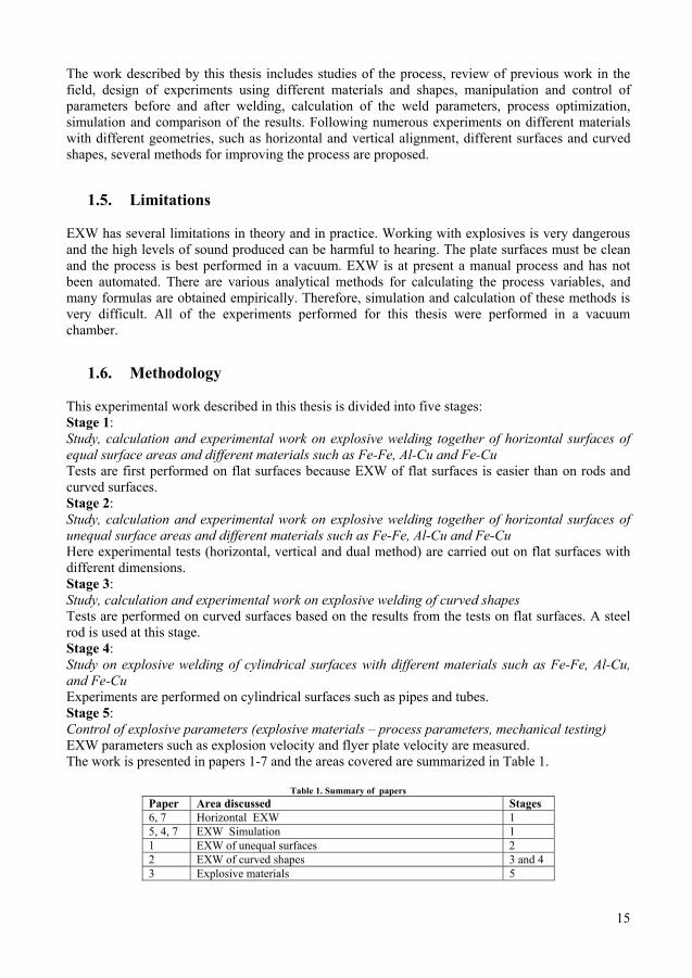
The work described by this thesis includes studies of the process, review of previous work in the field, design of experiments using different materials and shapes, manipulation and control of parameters before and after welding, calculation of the weld parameters, process optimization, simulation and comparison of the results. Following numerous experiments on different materials with different geometries, such as horizontal and vertical alignment, different surfaces and curved shapes, several methods for improving the process are proposed.
1.5. Limitations EXW has several limitations in theory and in practice. Working with explosives is very dangerous and the high levels of sound produced can be harmful to hearing. The plate surfaces must be clean and the process is best performed in a vacuum. EXW is at present a manual process and has not been automated. There are various analytical methods for calculating the process variables, and many formulas are obtained empirically. Therefore, simulation and calculation of these methods is very difficult. All of the experiments performed for this thesis were performed in a vacuum chamber.
1.6. Methodology
This experimental work described in this thesis is divided into five stages: Stage 1: Study, calculation and experimental work on explosive welding together of horizontal surfaces of equal surface areas and different materials such as Fe-Fe, Al-Cu and Fe-Cu Tests are first performed on flat surfaces because EXW of flat surfaces is easier than on rods and curved surfaces. Stage 2: Study, calculation and experimental work on explosive welding together of horizontal surfaces of unequal surface areas and different materials such as Fe-Fe, Al-Cu and Fe-Cu Here experimental tests (horizontal, vertical and dual method) are carried out on flat surfaces with different dimensions. Stage 3: Study, calculation and experimental work on explosive welding of curved shapes Tests are performed on curved surfaces based on the results from the tests on flat surfaces. A steel rod is used at this stage. Stage 4: Study on explosive welding of cylindrical surfaces with different materials such as Fe-Fe, Al-Cu, and Fe-Cu Experiments are performed on cylindrical surfaces such as pipes and tubes. Stage 5: Control of explosive parameters (explosive materials – process parameters, mechanical testing) EXW parameters such as explosion velocity and flyer plate velocity are measured. The work is presented in papers 1-7 and the areas covered are summarized in Table 1.
Table 1. Summary of papers Paper Area discussed Stages 6, 7 Horizontal EXW 1 5, 4, 7 EXW Simulation 1 1 EXW of unequal surfaces 2 2 EXW of curved shapes 3 and 4 3 Explosive materials 5
16
1.7. Thesis Outline This thesis describes research during which more than 100 experiments were performed and the results were applied in a large aluminum production company. There are at least 3 patentable technologies described in the results. The thesis is organised as follows: Part 1 Introduction: including background, objectives, motivation, limitations of the studies, presentation of the methodology, formulation of the problem and outline of the thesis. Part 2 Theory: including definitions and expressions used in the thesis, and presentation of theory in preparation for the scientific discussion. Part 3 Experimental Data and Results: including the experimental set up, results and test reports. Part 4 Discussion: including discussion of results, calculations, and future work. Part 5 Conclusions: including conclusions and practical output. Part 6 References Part 7 Summary of Papers
17
2. Theory
2.1. Mechanism and set up
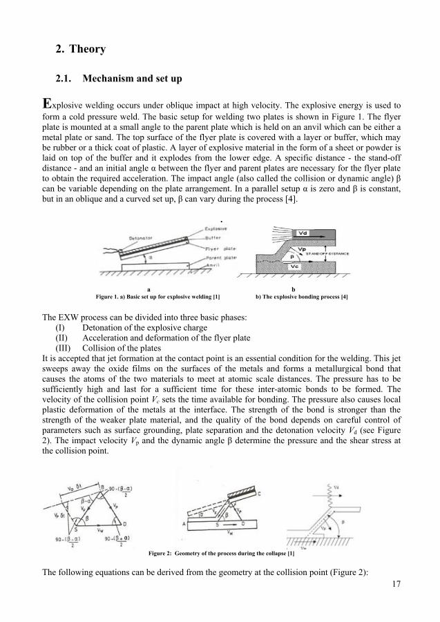
Explosive welding occurs under oblique impact at high velocity. The explosive energy is used to form a cold pressure weld. The basic setup for welding two plates is shown in Figure 1. The flyer plate is mounted at a small angle to the parent plate which is held on an anvil which can be either a metal plate or sand. The top surface of the flyer plate is covered with a layer or buffer, which may be rubber or a thick coat of plastic. A layer of explosive material in the form of a sheet or powder is laid on top of the buffer and it explodes from the lower edge. A specific distance - the stand-off distance - and an initial angle α between the flyer and parent plates are necessary for the flyer plate to obtain the required acceleration. The impact angle (also called the collision or dynamic angle) β can be variable depending on the plate arrangement. In a parallel setup α is zero and β is constant, but in an oblique and a curved set up, β can vary during the process [4].
.
a b Figure 1. a) Basic set up for explosive welding [1] b) The explosive bonding process [4]
The EXW process can be divided into three basic phases:
(I) Detonation of the explosive charge (II) Acceleration and deformation of the flyer plate (III) Collision of the plates
It is accepted that jet formation at the contact point is an essential condition for the welding. This jet sweeps away the oxide films on the surfaces of the metals and forms a metallurgical bond that causes the atoms of the two materials to meet at atomic scale distances. The pressure has to be sufficiently high and last for a sufficient time for these inter-atomic bonds to be formed. The velocity of the collision point Vc sets the time available for bonding. The pressure also causes local plastic deformation of the metals at the interface. The strength of the bond is stronger than the strength of the weaker plate material, and the quality of the bond depends on careful control of parameters such as surface grounding, plate separation and the detonation velocity Vd (see Figure 2). The impact velocity Vp and the dynamic angle β determine the pressure and the shear stress at the collision point.
Figure 2: Geometry of the process during the collapse [1]
The following equations can be derived from the geometry at the collision point (Figure 2):
18
��
sin�� � �� ���
cos�� � �2 �
���
���
sin�� � ��
cos�� � �2 �
�2 sin�� � �
2 � cos�� � �2 �
cos�� � �2 �
� ��
��� sin����
�� (1)
From the sine equations in triangle SBD we can write:
��
cos �� � �2 �
���
cos �� � �2 �
���
sin � �
�� � �� � ���������
� �
��� � (2)
�� � ���������
� �
��� � (3)
Where �� is the velocity of the flyer plate in relation to point s and �� is the velocity of welding, equal to the collision velocity ��. In a parallel set up α=0 and �� = �� = ��, and from the previous equations:
� �� � �� � �� � �� � ��
2 sin�2� (4)
The selection of parameters is based on the mechanical properties, density, and shear wave velocity of each component, and many of these are determined experimentally. Considerable progress has been made in setting up the optimum parameters required to produce an acceptable bond. The parameters involved in the process (such as ��, ��, ��, α � �, etc.) are defined in a special diagram called the Welding Window (WW) that has been proposed by various authors [36].
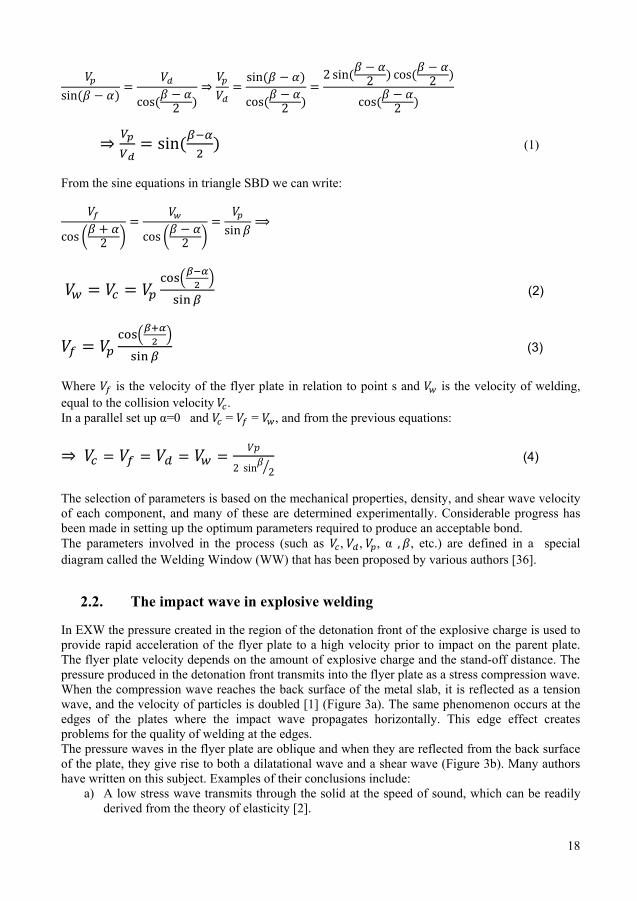
2.2. The impact wave in explosive welding In EXW the pressure created in the region of the detonation front of the explosive charge is used to provide rapid acceleration of the flyer plate to a high velocity prior to impact on the parent plate. The flyer plate velocity depends on the amount of explosive charge and the stand-off distance. The pressure produced in the detonation front transmits into the flyer plate as a stress compression wave. When the compression wave reaches the back surface of the metal slab, it is reflected as a tension wave, and the velocity of particles is doubled [1] (Figure 3a). The same phenomenon occurs at the edges of the plates where the impact wave propagates horizontally. This edge effect creates problems for the quality of welding at the edges. The pressure waves in the flyer plate are oblique and when they are reflected from the back surface of the plate, they give rise to both a dilatational wave and a shear wave (Figure 3b). Many authors have written on this subject. Examples of their conclusions include:
a) A low stress wave transmits through the solid at the speed of sound, which can be readily derived from the theory of elasticity [2].

18
��
sin�� � �� ���
cos�� � �2 �
���
���
sin�� � ��
cos�� � �2 �
�2 sin�� � �
2 � cos�� � �2 �
cos�� � �2 �
� ��
��� sin����
�� (1)
From the sine equations in triangle SBD we can write:
��
cos �� � �2 �
���
cos �� � �2 �
���
sin � �
�� � �� � ���������
� �
��� � (2)
�� � ���������
� �
��� � (3)
Where �� is the velocity of the flyer plate in relation to point s and �� is the velocity of welding, equal to the collision velocity ��. In a parallel set up α=0 and �� = �� = ��, and from the previous equations:
� �� � �� � �� � �� � ��
2 sin�2� (4)
The selection of parameters is based on the mechanical properties, density, and shear wave velocity of each component, and many of these are determined experimentally. Considerable progress has been made in setting up the optimum parameters required to produce an acceptable bond. The parameters involved in the process (such as ��, ��, ��, α � �, etc.) are defined in a special diagram called the Welding Window (WW) that has been proposed by various authors [36].
2.2. The impact wave in explosive welding In EXW the pressure created in the region of the detonation front of the explosive charge is used to provide rapid acceleration of the flyer plate to a high velocity prior to impact on the parent plate. The flyer plate velocity depends on the amount of explosive charge and the stand-off distance. The pressure produced in the detonation front transmits into the flyer plate as a stress compression wave. When the compression wave reaches the back surface of the metal slab, it is reflected as a tension wave, and the velocity of particles is doubled [1] (Figure 3a). The same phenomenon occurs at the edges of the plates where the impact wave propagates horizontally. This edge effect creates problems for the quality of welding at the edges. The pressure waves in the flyer plate are oblique and when they are reflected from the back surface of the plate, they give rise to both a dilatational wave and a shear wave (Figure 3b). Many authors have written on this subject. Examples of their conclusions include:
a) A low stress wave transmits through the solid at the speed of sound, which can be readily derived from the theory of elasticity [2].
19
b) At high pressure, as in a shock wave, the shear strength becomes negligible compared to the pressure and the material behaves like a fluid [3]. c) El-Sobky and Blazynski [1] suggested a mechanism for the stress wave, represented in Figure 3d. In their model, a single compression wave (symbolized by a full circle) is generated at the collision point, while successive reflections from both the flyer and parent plate (represented by the dashed circles) generate the wavy shape at the contact point that can be seen under the SEM microscope.
a
b
c d Figure 3. Impact wave reflection [1]
a) Reflection of a compressive stress wave from back surface of the metal plate b) Detonation of a layer of explosive in contact with a metal plate
c) Stress wave mechanism of surface wave formationd) The wavy shape of the contact point
2.3. Predicting the wavelength
Figure 4 shows the shape of the impact wave at the interface of the plates. The wavelength can be derived from this figure as follows:
Figure 4. Shape of the wave at the interface of the plates [1]
λ = C . A (7) Where A is amplitude and C is a constant.
λ2A
xx
20
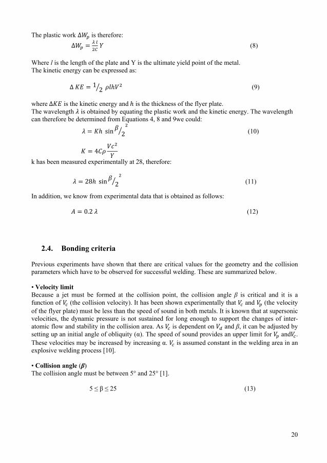
The plastic work ��� is therefore: ��� � � �
�� � (8)
Where l is the length of the plate and Y is the ultimate yield point of the metal. The kinetic energy can be expressed as:
� �� � 12� ����� (9)
where ��� is the kinetic energy and � is the thickness of the flyer plate. The wavelength � is obtained by equating the plastic work and the kinetic energy. The wavelength can therefore be determined from Equations 4, 8 and 9we could:
� � �� ��� �2�
� (10)
� � ������
� k has been measured experimentally at 28, therefore:
� � 2�� ��� �2�
� (11)
In addition, we know from experimental data that is obtained as follows:
� � ��2 � (12)
2.4. Bonding criteria Previous experiments have shown that there are critical values for the geometry and the collision parameters which have to be observed for successful welding. These are summarized below. • Velocity limit Because a jet must be formed at the collision point, the collision angle β is critical and it is a function of �� (the collision velocity). It has been shown experimentally that �� and �� (the velocity of the flyer plate) must be less than the speed of sound in both metals. It is known that at supersonic velocities, the dynamic pressure is not sustained for long enough to support the changes of inter-atomic flow and stability in the collision area. As �� is dependent on �� and β, it can be adjusted by setting up an initial angle of obliquity (α). The speed of sound provides an upper limit for �� and��. These velocities may be increased by increasing α. �� is assumed constant in the welding area in an explosive welding process [10]. • Collision angle (β) The collision angle must be between 5° and 25° [1]. 5 ≤ β ≤ 25 (13)
20
The plastic work ��� is therefore: ��� � � �
�� � (8)
Where l is the length of the plate and Y is the ultimate yield point of the metal. The kinetic energy can be expressed as:
� �� � 12� ����� (9)
where ��� is the kinetic energy and � is the thickness of the flyer plate. The wavelength � is obtained by equating the plastic work and the kinetic energy. The wavelength can therefore be determined from Equations 4, 8 and 9we could:
� � �� ��� �2�
� (10)
� � ������
� k has been measured experimentally at 28, therefore:
� � 2�� ��� �2�
� (11)
In addition, we know from experimental data that is obtained as follows:
� � ��2 � (12)
2.4. Bonding criteria Previous experiments have shown that there are critical values for the geometry and the collision parameters which have to be observed for successful welding. These are summarized below. • Velocity limit Because a jet must be formed at the collision point, the collision angle β is critical and it is a function of �� (the collision velocity). It has been shown experimentally that �� and �� (the velocity of the flyer plate) must be less than the speed of sound in both metals. It is known that at supersonic velocities, the dynamic pressure is not sustained for long enough to support the changes of inter-atomic flow and stability in the collision area. As �� is dependent on �� and β, it can be adjusted by setting up an initial angle of obliquity (α). The speed of sound provides an upper limit for �� and��. These velocities may be increased by increasing α. �� is assumed constant in the welding area in an explosive welding process [10]. • Collision angle (β) The collision angle must be between 5° and 25° [1]. 5 ≤ β ≤ 25 (13)
21
• Pressure limit A minimum impact pressure ( ) is required to impart sufficient impact energy to produce a weld. It has been suggested by Wylie et al. [1] that the impact energy required is related to the strain energy and the dynamic yield strength of the flyer plate. The upper limit of the impact energy is determined by the need to avoid excess heat and possible melting by viscous dissipation and the consequent formation of weak layers. This upper limit depends to the lower melting point of the weld. • Stand-off The stand-off distance must be sufficient to allow the flyer plate to accelerate to the required impact velocity. The minimum stand-off distance has been empirically determined as half the thickness of the flyer plate. An empirically determined formula for the suggested stand-off distance [1] is: S=3 K Xe C/M (14) Where S is the stand-off distance, K is between 4 and 7, depending on the impact velocity, M is the flyer plate mass, C is the explosion mass and Xe is the thickness of explosive material. • Surface flatness The flatness is very important in the EXW process. This is because imperfections in the surface cause the jet to be concentrated at a point, which produces high temperatures at the contact points, thereby preventing high quality welding. For a successful test, surface flatness in the range of 2 to 3 microns is sufficient. • Explosive material High velocity explosive materials are not used in the EXW process because of the risk of damage to the flyer plate during the test. A special diagram called the welding window or weld-ability window is used to describe the state of plates at the interface and in the weld area. The critical parameters used to establish a weld-ability window are • The critical impact angle for jet formation • The collision velocity • The kinetic energy and impact pressure that is indicated by
2.5. Welding window The welding window (WW) includes straight and curved regions. In order to draw the WW the relationships between the initial conditions (the angles α and β and the characteristics of the explosive) must be established. The WW lies within the boundaries of 7 parameters as shown in Figure 5. The parameters α, β, , , ,, and the properties of the material determine the WW. This diagram can be drawn in both the - β and - β plane and displays an area within which the weld is available. In this thesis the WW is drawn only in the - β plane.

22
Figure 5. An example of a WW diagram in the Vc-β plane
Critical angle limit for jet formation [line a-a] The most important condition for welding is jet formation. This must occur at the contact point for successful welding to occur. Theoretically, jetting will occur if �� remains subsonic. However, in practice a minimum angle is necessary to satisfy the pressure requirements. Jetting occurs to the left of the line a-a in Figure 5, which represents the critical angle βc which is necessary for jetting. Abrahamson suggests the following relationship between β and �� [24]:
β = 10(��-5.5) (15)
Upper limit of �� [line b-b] Line b-b in Figure 5 describes the upper limit of ��, which is predictable at 1.2 to 1.5 times the speed of sound, and which also limits the other WW parameters. Lower and upper limit of β [lines c-c and d-d] The lower and upper limits of the dynamic angle β were experimentally obtained by Bahrani and Crosslan [21]. They suggested a lower limit of between 2° and 3° and upper limit of 31° for β in a parallel geometry. Suggested minimum and maximum values of the initial angle α in an inclined set up are 3° and 18° respectively. Lower limit of �� [line e-e] Equation 16 defines the lower limit of �� for bonding as proposed by Simonov [10]. �� � � �2�� �� ��
�� (16) Cowan [27] defined the lower limit of �� according to the fluid hypothesis as follows:
�� � � �� ������2
2������� (17)
23
Where Re is the Reynolds number, H is the Vickers hardness (� ��� � and F and B stand for flyer and base plates respectively. The lower limit of �� can be determined at the transition limit which occurs at Re=10.6. Lower limit of impact critical pressure (��) [line f-f] Equation 18 shows the lower limit for welding of β in radians, where H is the Vickers hardness in N/m2 and ρ is the density in kg/m3. β=1.14 � ��
� �����
�� (18)
The equation simplifies to: β ��= cte (19) Hardness is derived from tensile stress as follows [1]:
Hv=5 � (20)
Wittman [7] also proposed a lower limit for �� as follows:
��=�����
���� (21)
Where σTU is the ultimate tensile stress and C is the bulk sound velocity. Equation 22 gives another formulation for the lower limit of �� [4]:
�� (min)� ���� ��� ��
�����
�� ��� (22)
Where A is a symbol for the plate with higher strength, � �� yield stress and U is the speed of sound in the metal. Equation 23 gives �� for the plates with the same material:
�� (min)� �����
(23)
Upper limit of �� [line g-g] Wittman gives the upper limit for welding as:
sin ��
� ����
��������� (24)
�� � ��2� , �� � �� �� , � � �
��� � 2���
Where t is the thickness of the flyer plate and k3 is experimentally determined with �� set to half the compressive wave velocity Cf. Wittman also suggested the following experimental formula:
Sin β/2=1/ ������ (25)

24
2.6. Governing equations The main governing equation for the EXW process is the equation of motion [37]:
� � � �� (26) A number of useful equations follow below. The collision velocity, dynamic angle and thickness of flyer plate are related to each other as follows: f =f (β,��, t) (27)
From plastic theory [37], the maximum pressure is expressed as:
P= ρ β C �� (28) Using the hydrodynamic method, the maximum pressure is: � � � ��
�
� (29)
Power in the EXW process is given by:
� � �� �� � �������
���������1 � ���
C� � ��
� �� (30)
Where Ei is strain energy, and m1 and m2 are the masses of flyer and parent plates [38]. From equation 30, �� is calculated as follows:
�� ���Opt. =C� √�
=0.557C0 (31) Equation 32 is an experimentally determined formula that relates the flyer plate velocity to the explosive velocity.
�� � 0.612 e/m2�e/m �� (32)
Where e/m is the ratio of mass of the explosive material to the mass of the flyer plate and buffer
2.7. Testing methods The main requirement to achieve the best quality welds is accurate calculation of EXW parameters. These parameters can be estimated from theory and experimentally. The most important of these are ��, ��, ��, β, explosion power and explosion sensitivity. Some of the important parameters can only be measured after welding. Other operations that are carried out after the welding process include mechanical testing, metallographic testing, NDT testing, machining, stress relief, cutting and sizing.
25
Tests to be carried out before welding:
a) Measuring and
Dutrich method One of the easiest and oldest methods for measuring the detonation velocity is the Dutrich method. In this method wire of length L with a detonation velocity is held in contact at two different points to an explosive material of unknown detonation velocity . The distance between the contact points is L1 (shown in Figure 6). The middle of the wire is marked on a thin aluminum, brass or lead plate. The explosive wave passes through both ends of the wire. They collide at a point a distance L2 from the middle of the wire. This collision creates a mark on the abovementioned plate.
Figure 6. Determination of detonation velocity by Dutrich method [4]
The time that it takes for the explosive wave to travel from each contact point to the collision point is the same.
t1=t2
L1 / VD+ (L /2 – L2)/ Vd= (L /2) / Vd + L2 / Vd
L1 / VD =2 L 2 / Vd
⇒ VD= Vd L1 / 2 L 2 (33)
L1, L2 and are known - can therefore be calculated from equation 33. Pin contactor method
can be measured using a complex recording system to record electrical pulses. In the EXW process when the flyer and parent plates are parallel, is equal to . This provides the basis for the pin contactor method. Velocity probe method
and can be calculated directly by using measuring probes to draw the location-time curve. Each probe includes a closed-ended aluminum tube and a sensitive insulating wire. The voltage variation after the explosion, caused by the decrease in the length of the insulating wire is measured and indicated by oscilloscope. Slanting wire method (for measuring and β)

26
This is a simple electrical method which is used to obtain contact parameters using electrical probes and an oscilloscope. Photographic method (for measuring ) This method can be used to measure continuously. Radiography method (for measuring β) This is similar to the photographic method except in that it uses X–rays. Radiography can be used to show the location and the moment of contact. The angle β is therefore measured directly.
b) Measuring explosive power
Ballistic mortar method In this method an explosive charge of 10 gram is used to fire a standard shot at the end of a pendulum. The angle of recoil following the explosion is measured and used to calculate the explosive power. Trauzl method In this method the explosive is placed in a cylindrical hole in a lead block. The remainder of the hole is filled with sand. The explosive power can be calculated by measuring the increase in the volume of the hole after detonation.
c) Measuring sensitivity
The sensitivity is used to determine the necessary load to initiate detonation. A small booster charge is placed between the detonator and the main charge. The mass of the booster charge required to initiate a stable detonation is used to calculate the sensitivity. Tests to be carried out after welding a) Primary tests These including sizing, cutting, machining and stress relief.
b) NDT tests Non destructive tests, including ultrasonic and radiography tests.
c) Mechanical tests
Impact resistance test The impact test is used to check the strength of a weld under dynamic load. Chisel or peel off test This is a simple but very important test, and is illustrated in Figure 7. A chisel is used to try to separate two the plates. Easy separation of the plates indicates incomplete welding.
Figure 7. The chisel test [1]
27
Tensile tests Including shear and tensile tests.
d) Metallographic tests
Metallographic tests are performed using scanning electron microscopy (SEM). SEM is a useful method for evaluating the quality of welding. Under SEM, a perfect weld has a uniformly wavy geometry. Irregularities or cracks indicate problems with the weld.
2.8. Simulation of the explosive welding process As most results of EXW have been obtained by explosive experiments, repetition of similar experiments can be avoided by using modeling and simulation. In addition, result prediction, parameter selection and wave distribution determination can be performed by simulation software. The most important simulation software packages in impact mechanics are ABAQUS, ANSYS, LS-DYNA, AUTODYN, RAVEN [39] and COMSOL [40]. Stress, strain, pressure, temperature distribution, behavior of materials and displacement of energy can be simulated in two or three dimensions. Figure 8 shows a 2D simulation of pressure distribution in an EXW process in AUTODYN software.
Figure 8. Pressure simulation by AUTODYN software [34]
COMSOL software is used to check results in some sections of this thesis [40].

28

28
29
3. Experimental Data, Results and Calculations
3.1. Experiment setup
The set up has been done in 5 stages: Stage 1: EXW experiments on horizontal and flat surfaces with different materials The materials used and their specifications are listed in Tables 2, 3, and 4. The setup for an experiment with a Fe-Fe joint is shown in Figure 9. Fe-Fe
Table 2. Specification of Fe-Fe horizontal setup No. Flyer plate Parent plate Stand-off .α Explosive .ρ VD Buffer Detonator
1 Fe-
Fe-
0 Ammonium-nitrate: 50 gr. dynamite : 10 gr.
.8 1.2
2000 3000
Al foil
1
2 Fe-
Fe-
4 dynamite : 40 gr. 1.5
4000
Al foil
1
Figure 9. Setup for Fe-Fe welding
Al-Cu
Table 3. Specification of Al-Cu horizontal setup Flyer plate Parent plate Stand-off .α Explosive VD Buffer Detonator
Al-
Cu-
0 Ammonium-nitrate: 110 gr. Dynamite: 40 gr.
.8 1.2
2000 3000
Al foil 1
Fe-Cu
Table 4. Specification of Fe-Cu horizontal setup Flyer plate Parent plate Stand-off .α Explosive ρ VD Buffer Detonator
Fe-
cu-
0 Ammonium-nitrate : 50 gr. Dynamite : 10 gr.
.8 1.2
2000 3000
Al foil 1
Stage 2: Experimental work on EXW experiments on unequal flat surfaces with different materials Horizontal, vertical and dual experiments were performed on unequal flat surfaces. These tests were performed prior to the subsequent stage of welding on curved shapes because explosive welding on cylindrical shapes is effectively welding on surfaces of unequal surface areas. The specifications of the experiments are shown in Tables 5 and 6. Figures 10 and 11 show the experimental setups of the different arrangements (horizontal, vertical and dual). In order to prevent problematic edge effects

when weldin Figure 1 Horizonta
No. Flyer p
1 Al 30�100 �
2 Al 50�120 �
Vertical u
Flyer plate
Al 50�120 ���� Al 50�120 ����
ding unequa10 and will b
al unequal s
plate Pare
�� ���
Cu-200
�� ���
Cu-200
nequal sur
TaParent plat
Cu-100 �200 �10�� Cu-100 �200 �10��
al surfaces dbe explaine
surface areTable 5. Sp
ent plate S
-100 �0 � 10��
-100 �0 � 10��
a
rface areas
able 6. Specificate Stand-of
���
���
different seted in subseq
eas (Al-Cu)ecification of AlStand-off
���
���
Figure 10. U a) b)
(Al-Cu) tion of Al-Cu Veff .α E
�
�
0 0
D7
D7
tups were uquent section
) -Cu, unequal suΑ Explos
0 Dynampowde75 ��
0 Dynampowde75 ��
Unequal surfaceAl-Cu, unequalAl-Cu, unequal
rtical unequal suExplosive
Dynamite po75 ���
Dynamite po75 ���
used for somns.
urface area, horizsive .ρ
miteer��
1.2 gr./
miteer��
1.2 gr./
e area set up l surface area, hosurface area, ho
urface area and .ρ
owder
owder
1.gr 1.gr
me experim
zontal set up VD
/��� 660m/s
/��� 660m/s
b
orizontal set up orizontal set up
dual method setρ VD
.2 r./���
.2 r./���
660m/s
660m/s
ments. These
Buffer
0
1 mm Paper
0 1 mm Paper
(first test) (second test)
t up Buffer
00
00
1 mm Paper 1 mm paper
30
e are shown
Detonator
1
1
Detonator
2 2
0
n
31
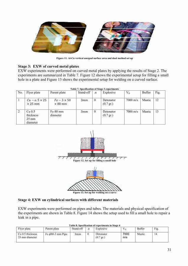
Figure 11. Al-Cu vertical unequal surface area and dual method set up
Stage 3: EXW of curved metal plates EXW experiments were performed on curved metal plates by applying the results of Stage 2. The experiments are summarized in Table 7. Figure 12 shows the experimental setup for filling a small hole in a plate and Figure 13 shows the experimental setup for welding on a curved surface.
Table 7. Specification of Stage 3 experiments No. Flyer plate Parent plate Stand-off .α Explosive VD Buffer Fig.
1
0 Detonator (0.7 gr.)
7000 m/s Mastic 12
2 Cu 0.5 thickness 25 mm diameter
Fe-80 mm diameter
0 Detonator (0.7 gr.)
7000 m/s Mastic 13
Figure 12. Set up for filling a small hole
Figure 13. Set up for welding on a curve
Stage 4: EXW on cylindrical surfaces with different materials EXW experiments were performed on pipes and tubes. The materials and physical specification of the experiments are shown in Table 8. Figure 14 shows the setup used to fill a small hole to repair a leak in a pipe.
Table 8. Specification of experiments in Stage 4 Flyer plate Parent plate Stand-off .α Explosive VD Buffer Fig.
Cu 0.5 thickness 25 mm diameter
Fe 80-3 mm Pipe 0 Detonator (0.7 gr.)
7000 m/s
Mastic 14

32
Figure 14. Set up for repairing a leak and filling a small hole in a pipe
Key: 1-flyer plate Cu, 2-pipe Fe, 3-stand-off, 4-filler Fe, 5-detonator holder, 6- detonator Stage 5: EXW Control parameters (explosive materials – process parameters, test results) The specification of experiments is shown in Table 9. Figures 15 and 16 show experimental setups for measuring Vd by the Dutrich method. Table 9. Specification of experiments in Stage 5 (Dutrich method) No. Wire
specification Plate specification
Explosive thickness
Explosive material
.ρ L1 L
1 Cortex 5gr/m Vd=6500m/s
8 mm AZAR* 1.4 gr./
2 Cortex 5gr/m Vd=6500m/s
8mm AZAR* 1.4 gr./
3 Cortex 5gr/m Vd=6500m/s
10mm AZAR* 1.4 gr./
4 Cortex 5gr/m Vd=6500m/s
12mm AZAR* 1.4 gr./
5 Cortex 5gr/m Vd=6500m/s
15mm AZAR* 1.4 gr./
6 Cortex 5gr/m Vd=6500m/s
20mm AZAR* 1.4 gr./
*AZAR is an explosive mixture that includes TNT and ammonium nitrate.
Figure 15. Dutrich method setup using a thin Aluminum plate
Figure 16. Dutrich method setup using a Brass plate
3.2. Stage 1 The results
Stage 2 Figure 18 (horizontal
Stage 3 Figure 19 shorizontal
Experim
s of explosiv
a
d
shows thl, vertical an
shows the reand curved
mental Res
ve welding
Fig
e results ond dual met
a
c Figur
esults of exd shapes.
sults
on horizont
gure 17. Results
of explosivthod).
re 18. EXW of un
a, b) Resu c, d) Resu
xplosive wel
tal and flat
b
e
of EXW on hori a, b, c )Experim d, e) Experime f) Experiment
ve welding
nequal surface aults of Al-Cu joiults of Al-Cu join
lding for fil
surfaces are
izontal flat surfaments for Fe-Fe ents for Fe-Fe wts for Fe-Fe weld
on materi
areas nt in horizontal nt in vertical and
ling a small
e shown in F
aces welding elding
ding
ials with u
b
setup d dual method s
l hole using
Figure 17.
c
f
unequal sur
d
etup
g a detonato
33
rface areas
r charge on
3
s
n
Stage 4 Fig 20 sho
Stage 5 The resultsthe explosiat the middaluminum
ws the resu
s of the expeion. The poidle point of and brass p
No.
1 2 3 4 5 6
ult of an EXW
Figure 20
eriments areint is marke
f the wire acplates.
a
TaThicknesmaterial (8 8 10 12 15 20
a Figure 19. EXW a) R b) R
W test for f
0. EXW with a d
e summarized by the efccording to D
Figure 21.
able 10. Result os of explosive(mm)
W tests for fillingResult of welding Result of welding
filling a sma
detonator on a p
zed in Tableffect of the eDutrich met
Dutrich methoda) Test on a thinb) Test on a Bra
of experiments de L2 m
met-----139125116110110
b g a hole
for filling a smag with a detonato
all hole in a
ipe for filling a s
e10. Figure explosion, sthod. The e
d test results n Aluminum platass plate
escribed in Tablmark accordinthod (mm) -----------------
9.25 5 6 0 0
all hole or on a curved sh
pipe.
small hole
21 shows thshowing thexperiment i
b
te
le 9 ng to Dutrich
--------------
hape
he contact pe length L2, is performed
34
point after and M is
d on both
4

Stage 4 Fig 20 sho
Stage 5 The resultsthe explosiat the middaluminum
ws the resu
s of the expeion. The poidle point of and brass p
No.
1 2 3 4 5 6
ult of an EXW
Figure 20
eriments areint is marke
f the wire acplates.
a
TaThicknesmaterial (8 8 10 12 15 20
a Figure 19. EXW a) R b) R
W test for f
0. EXW with a d
e summarized by the efccording to D
Figure 21.
able 10. Result os of explosive(mm)
W tests for fillingResult of welding Result of welding
filling a sma
detonator on a p
zed in Tableffect of the eDutrich met
Dutrich methoda) Test on a thinb) Test on a Bra
of experiments de L2 m
met-----139125116110110
b g a hole
for filling a smag with a detonato
all hole in a
ipe for filling a s
e10. Figure explosion, sthod. The e
d test results n Aluminum platass plate
escribed in Tablmark accordinthod (mm) -----------------
9.25 5 6 0 0
all hole or on a curved sh
pipe.
small hole
21 shows thshowing thexperiment i
b
te
le 9 ng to Dutrich
--------------
hape
he contact pe length L2, is performed
34
point after and M is
d on both
4 35
3.3. Calculation, numerical and simulation results Welding window WWs are drawn for the experiments. Results of some sample calculations are shown below. Cu-Fe (Tables 7 and 8) Flyer plate: Cu � � 0���� � � ��9� �� ����� � � ���� ���� � � 4900� �⁄
Parent plate: Fe � � ���� � � ��� �� ����� � � �0�� ���� � � �000� �⁄
Line a-a Table 11 shows the results of calculations using Equation 15.
Table 11. Calculation for line (a-a) � 0 5 10 15 20 25 30 35 40 45
�� 5.5 6 6.5 7 7.5 8 8.5 9 9.5 10
Line b-b From Section 2.5 we get: �� � ��� � 4900 � ���0� �⁄ Line c-c From Section 2.5 we get: � � � Line d-d From Section 2.5 we get: � � �� Line e-e Equation 17 gives �� as follows:
�0�� � ��������������������������
��� � �� �� ���0� �⁄ Line f-f Equation 21 gives �� as follows:
�� � �4� � �0� � 9��
4900 �� �� � �00� �⁄ Equation 22 gives �� as follows:
�� min=�0 � 40 � �0� � 9�� ������������
�������������������
� � ��0� �⁄
For an increased safety margin the higher value (300 m/s) is used and �� is calculated from Equation 4. The results are shown in Table 12.
Table 12. Calculation for line (f-f) � 3 5 10 20 30 40
�� 5.7 3.52 1.72 0.86 0.57 0.44
36
Line g-g Equation 25 gives �� as follows:
��=� �
����������
The results are shown in Table 13.
Table 13. Calculation for line (g-g) � 0 5 10 15 20 25 30 35
�� ------------- 12.25 7 .15 4.06 3.4 2.95 2.61
The WW for Cu- Fe is drawn using these results and is shown in Figure 22. The weld-able area is indicated by the crosshatched area.
Figure 22. WW for Cu-Fe joint Fe-Fe (Table 2) Flyer plate: Fe � � � �� � � ��� ��
��� � � � �� ������ � � ���� � �⁄
Parent plate: Fe � � � �� � � ��� ����� � � � �� ��
���� � � ���� � �⁄
Line a-a Table 14 gives the results of calculations using Equation 15.
Table 14. Calculation for line (a-a) � 0 5 10 15 20 25 30 35 40 45
�� 5.5 6 6.5 7 7.5 8 8.5 9 9.5 10
Line b-b From Section 2.5 we get: �� � ��� � ���� � ���� � �⁄ Line c-c From Section 2.5 we get: � � ��
37
Line d-d From Section 2.5 we get: � � ��� Line e-e Equation 17 gives �� as follows:
���� � ����������������
��� � ��=1460� �⁄ Line f-f Equation 21 gives �� as follows:
��=(����������
������ �� � ���� �⁄
Vc is obtained from Equation 4 and the results are shown in Table15.
Table 15. Calculation for line (f-f) � 3 5 10 20 30 40
�� 5.1 3.18 1.55 0.77 0.51 0.4
Line g-g Equation 25 gives �� as follows:
��=� �
���� ������
These results are shown in Table 16.
Table 16. Calculation for line (g-g) � 0 5 10 15 20 25 30 35
�� -------- 12.25 7 .15 4.06 3.4 2.95 2.61
The WW for Fe-Fe is drawn from these results (Figure 23) and the weld able area is indicated.
Figure 23. Welding window for Fe-Fe joint Al-Cu (Tables 5 and 6) Flyer plate: Al �� � ���� � � ��� �� ����� ����������������������� � �� �� ����
� � ����� �⁄ �� � ���� ����
38
Parent plate: Cu � � ����� � � ���� �� ����� ��������������� � �� �� ����
� � ����� �⁄ ������������������ � �� �� ����
Line a-a Table 17 shows the results of the calculation using Equation 15.
Table 17. Calculation for line (a-a)
� 0 5 10 15 20 25 30 35 40 45
�� 5.5 6 6.5 7 7.5 8 8.5 9 9.5 10
Line b-b From Section 2.5 we get: �� � ��� � ���� � ����� �⁄ Line c-c From Section 2.5 we get: � � �� Line d-d From Section part 2.5 we get: � � ��� Line e-e Equation 17 gives �� as follows:
���� � ��������������������������
��� � �� =1466� �⁄ Line f-f Equation 22 gives �� as follows:
��= (����������
������ �� � ���� �⁄
��= (����������
������ �� � ���� �⁄
Equation 22 gives �� as follows:
�� min=�� � �� � ��� � ��� ������������
�������������������
� � ���� �⁄
For greater safety we use �� =200 and from Equation 4, �� can be obtained. The results are shown in table 18.
Table 18. Calculation for line (f-f) � 3 5 10 20 30 40
�� 3.8 2.34 1.14 0.57 0.38 0.29
Line g-g Equation 22 gives �� as follows: �� � � �
���� ������
The result is shown in Table 19.
Table 19. Calculation for line (g-g) � 0 5 10 15 20 25 30 35
�� ---------- 12.25 7 .15 4.06 3.4 2.95 2.61
39
Figure 24 shows the WW for Al-Cu drawn from these results. The weld able area is indicated.
Figure 24. WW for Al-Cu joint Explosive material EXW experiments (horizontal and vertical) are arranged in a parallel setup with α=0 and �� =��. By considering WW curves, a suitable detonation velocity and collision angle can be obtained. �� = �� = 2500-6000 m/s β = 25-10 �� = 6000, β = 10 The ratio e/m can be calculated from Equations 4 and 32:
0.612 � �⁄2 � � �⁄
�����
� 2 ����2 � 0.1�� � � �⁄ � 0.�
where e is the explosive mass and m is the flyer plate mass. For example, for an iron flyer plate weighing 100 grams, the explosive mass is estimated to be 80 grams. An alternative calculation for �� uses Equation 31 as follows: �� = 0.557 C0 �� = �� = 0.557×6000 = 3462 flyer plate Fe �� = �� = 0.557 ×4900 = 2822 flyer plate Cu �� = �� = 0.557×6400 = 3692 flyer plate Al β can be calculated from �� using Equation 18 as follows:
For Al with �� =3692� � � 1.1�� ���.�������
���=.09 radian =5.5°
Stand-off distance As described in Section 2.4, the stand-off distance is selected at half or equal to the thickness of the flyer plate. The optimum energy for jet formation may be obtained by varying the stand-off distance.

40
Calculation for Stage 5 �� is given by Equation 33 according to the results from Tables 9 and 10 as shown below. L1=150 mm, L=950 mm, L2=139 mm, �� =6500 m/s
⇒ ��= �� L1 / 2 L2 ⇒ ��=��������������2� � �������
Table 20 shows the results of calculation of �� for different thicknesses of explosive material.
Table 20. Calculation of VD for different thicknesses of explosive material No. Thickness
(mm) L2 mark (mm)
VD (m/s)
1 -------- 8 ------ 2 139.25 8 3500 3 125 10 3900 4 116 12 4200 5 110 15 4500 6 110 20 4500
Table 21 shows the measured detonation velocities in tests with different explosive materials of different thicknesses at high, medium and low explosion velocities.
Table 21. Results of testing on measuring detonation velocity for different kinds of explosive materials
Thickness of explosion (mm)
High velocity explosion Vd (m/s)
Medium velocity explosion Vd (m/s)
Low velocity explosion Vd (m/s)
0 0 0 0 5 5000 2600 1500 10 7300 3800 2200 15 7500 4500 2700 20 7500 5000 2900 25 7500 5000 3100 30 7500 5000 3300 35 7500 5000 3300
Wavelength Equations 11 and 12 give the wavelength and amplitude for a 3 mm Fe plate and a dynamic angle β=10°.
� � 2�� ��� �2�
�� 2� � � � ��� ��
�
�� ���� ��
� � ��2 � � ���� �� � � � ���� �� � � ������
Similarly, for a 5 mm Al plate and β=6° we get � � ���� �� ��� � � ���� ��
3.4. Test Results Measuring explosive parameters before welding Measuring �� Figures 25 and 26 show the effect of the thickness of explosive material on detonation velocity as recorded in Tables 20 and 21, found by the Dutrich method.
41
0500
100015002000250030003500400045005000
0 10 20 30
T mm
VD m
/s
Figure 25. Effect of explosive material thickness on detonation velocity
Figure 26. Effect of explosive material thickness on detonation velocity in general
(High, medium and low explosive velocity) Measuring explosive parameters after welding Chisel test Figure 27 shows the chisel test for peeling of the metal pieces.
Figure 27. Chisel test for 2 types of weld Mechanical tests Tables 22 and 23 show the results of mechanical tests - bond strength of explosive weld (BSEW) - in two directions (width and length) for the two setups described in Table 6 and Figure 15. These results are illustrated in Figures 28 and 29.
0
2000
4000
6000
8000
0 10 20 30 40
T mm
Vd m
/s
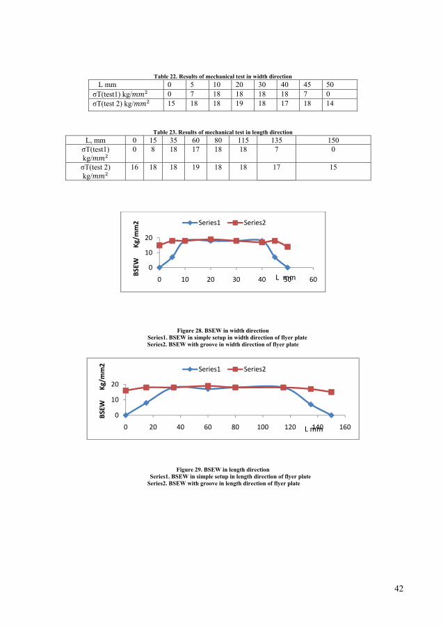
42
Table 22. Results of mechanical test in width direction L mm 0 5 10 20 30 40 45 50 σT(test1) kg/ 0 7 18 18 18 18 7 0 σT(test 2) kg/ 15 18 18 19 18 17 18 14
Table 23. Results of mechanical test in length direction L, mm 0 15 35 60 80 115 135 150 σT(test1) kg/
0 8 18 17 18 18 7 0
σT(test 2) kg/
16 18 18 19 18 18 17 15
Figure 28. BSEW in width direction Series1. BSEW in simple setup in width direction of flyer plate
Series2. BSEW with groove in width direction of flyer plate
Figure 29. BSEW in length direction Series1. BSEW in simple setup in length direction of flyer plate
Series2. BSEW with groove in length direction of flyer plate
0
10
20
0 10 20 30 40 50 60
BSEW
Kg
/mm2
Series1 Series2
L mm
0
10
20
0 20 40 60 80 100 120 140 160
BSEW
Kg
/mm2
Series1 Series2
L mm
MetallogrFigure 30 smeasured f
Simulation COMSOL based on ptransfer, imknowledgepossible toproperties,the system
Numerical of the expltheir intervariables, points indemixture wi
aphic tests shows the refrom these t
n results
software ispartial diffempact and e of mathemo construct loads, con
m.
simulationlosive and tractions areexpressionsependently ith = 600
esults of SEtests.
a
c
s a powerfuerential equ
diffusion matics or nut models bystraints, sou
s of the expthe upper sue specified s, or numbeof the comp
00 m/s.
EM scans of
Figure 3
ul environmuations (PD
can be peumerical any defining urces, and f
periments arurface of th
by appropers are appputational m
f the test we
30. Metallograph a, b) Al-Cu tes c, d) Al-Fe test
ment for moEs). Many
erformed wnalysis. By u
the relevafluxes — ra
re carried ouhe flyer platpriate cont
plied directlmesh. The l
elds. Wavel
hic results st t
odeling and types of si
with this sousing the ph
ant physicalather than b
ut using COte are repretact algorithly to solid loading is d
ength and a
b
d
solving maimulations oftware, tohysics modl quantitiesby defining
OMSOL V3esented by ihms. In thdomains, b
due to the de
amplitude w
any types osuch as aqugether with
de of this sos — such athe basic e
3.4a. The lowindependenthese experiboundaries, etonation o
43
were
of problemsuatics, heath in depth
oftware it isas materialquations of
wer surfacet nodes andiments, theedges, andf an AZAR
3
s t h s l f
e d e d R
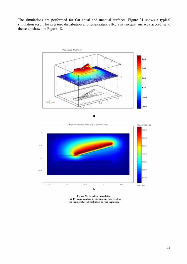
44
The simulations are performed for flat equal and unequal surfaces. Figure 31 shows a typical simulation result for pressure distribution and temperature effects in unequal surfaces according to the setup shown in Figure 18.
a
b
Figure 31. Results of simulation a) Pressure contour in unequal surface welding
b) Temperature distribution during explosion
45
4. Discussion and future work
4.1. Discussion Requirements for successful bonding
Suitable setups for successful bonding can be identified through tests to measure various variables. Like a series of carriages that make up a train, a series of diagrams can be constructed, and the WW in this composite diagram describes the test space where a successful weld can occur. In the absence of this composite diagram, it is assumed that the most pertinent relationship is the one between the pressure P, the impact velocity , parent plate velocity , and the effective strain. The flyer plate attains its peak velocity at the collision point. On impact the velocity of the parent plate at the collision point increases while the flyer plate velocity decreases. Under certain conditions, the velocities of the flyer and the parent plate are the same. When the situation stabilizes at the collision point and the pressure is high, inter-atomic bonding occurs. Metallographic Tests A fine structure was observed in most of the welding boundaries in SEM tests performed following the EXW process. Nearly all the experiments with different shapes showed successful bonding. Microstructure results of bonding are shown in Figures 30, which also shows the wavy pattern. In the tests performed here, λ was measured at 0.7 mm and A was 0.14. These values confirmed the results of the theoretical calculations in Section 3.3. Chisel or Peel off Test The bond strengths were measured by peel off and chisel tests. In some experiments, perfect results were achieved (Figure 27), and there were no physical differences between the metals. The rupture in these cases was in the weaker metal and away from the contact point. This was a confirmation of the high quality of welding. Other experiments showed less impressive results, with joints that separated easily (Figure 17a and c). This is likely to be for one of two main reasons - insufficient explosive material or dirty surfaces. Tensile Test BSEW were measured in two directions in Stages 2 and 3. These tests showed that the bond strengths were constant in the improved test with grooves throughout the contact surface according to the setup shown in Figure 10b. In experiments using surfaces that lack grooves BSEW is very low at the edges and increases towards the middle of the welding area. Figures28 and 29 show that the strength reaches the maximum value within 1 to 1.5 times the thickness of the flyer plate from the edge. In the second test the edges were uniform and produced suitable joints after jumping. This method is unique and is suitable for jointing two metals with different surfaces and does not have the edge strength problems seen in Figures 28 and 29.
Discussion of Stage 4 (removing leakage) The setup is one of the main problems when plugging a hole to stop leakage. The problem is particularly difficult when the weld has to be applied in a wet area. A simple package is therefore very desirable. This package includes detonator, a piece of thin copper plate, a piece of mastic as holder, a piece of iron as filler and small rods to provide the stand-off. Figure 19a shows a horizontal set up with the parent plate on the ground, which acts as an anvil. Figure 19b shows a curved set up with a rod as the parent plate. Figure 20 shows a curved set up with a pipe as the parent plate. If the explosive is too high, the pipe may be damaged. A detonator has a small amount
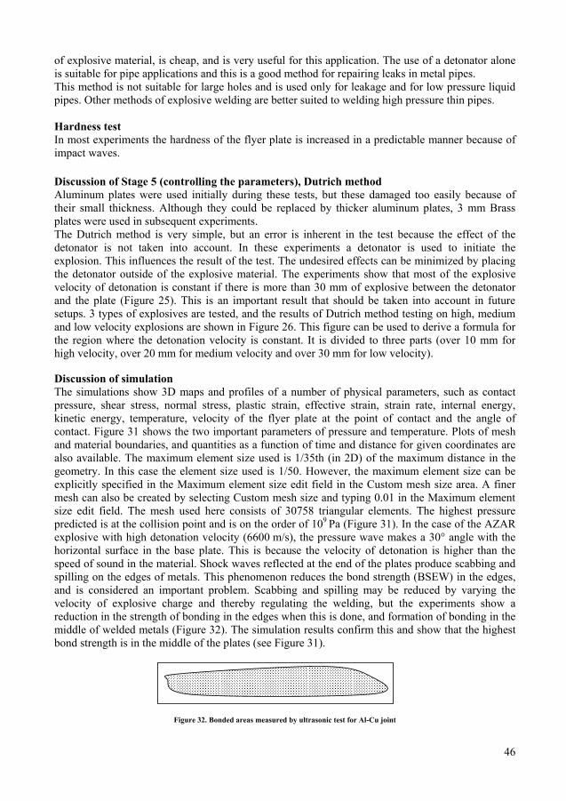
46
of explosive material, is cheap, and is very useful for this application. The use of a detonator alone is suitable for pipe applications and this is a good method for repairing leaks in metal pipes. This method is not suitable for large holes and is used only for leakage and for low pressure liquid pipes. Other methods of explosive welding are better suited to welding high pressure thin pipes. Hardness test In most experiments the hardness of the flyer plate is increased in a predictable manner because of impact waves. Discussion of Stage 5 (controlling the parameters), Dutrich method Aluminum plates were used initially during these tests, but these damaged too easily because of their small thickness. Although they could be replaced by thicker aluminum plates, 3 mm Brass plates were used in subsequent experiments. The Dutrich method is very simple, but an error is inherent in the test because the effect of the detonator is not taken into account. In these experiments a detonator is used to initiate the explosion. This influences the result of the test. The undesired effects can be minimized by placing the detonator outside of the explosive material. The experiments show that most of the explosive velocity of detonation is constant if there is more than 30 mm of explosive between the detonator and the plate (Figure 25). This is an important result that should be taken into account in future setups. 3 types of explosives are tested, and the results of Dutrich method testing on high, medium and low velocity explosions are shown in Figure 26. This figure can be used to derive a formula for the region where the detonation velocity is constant. It is divided to three parts (over 10 mm for high velocity, over 20 mm for medium velocity and over 30 mm for low velocity). Discussion of simulation The simulations show 3D maps and profiles of a number of physical parameters, such as contact pressure, shear stress, normal stress, plastic strain, effective strain, strain rate, internal energy, kinetic energy, temperature, velocity of the flyer plate at the point of contact and the angle of contact. Figure 31 shows the two important parameters of pressure and temperature. Plots of mesh and material boundaries, and quantities as a function of time and distance for given coordinates are also available. The maximum element size used is 1/35th (in 2D) of the maximum distance in the geometry. In this case the element size used is 1/50. However, the maximum element size can be explicitly specified in the Maximum element size edit field in the Custom mesh size area. A finer mesh can also be created by selecting Custom mesh size and typing 0.01 in the Maximum element size edit field. The mesh used here consists of 30758 triangular elements. The highest pressure predicted is at the collision point and is on the order of 109 Pa (Figure 31). In the case of the AZAR explosive with high detonation velocity (6600 m/s), the pressure wave makes a 30° angle with the horizontal surface in the base plate. This is because the velocity of detonation is higher than the speed of sound in the material. Shock waves reflected at the end of the plates produce scabbing and spilling on the edges of metals. This phenomenon reduces the bond strength (BSEW) in the edges, and is considered an important problem. Scabbing and spilling may be reduced by varying the velocity of explosive charge and thereby regulating the welding, but the experiments show a reduction in the strength of bonding in the edges when this is done, and formation of bonding in the middle of welded metals (Figure 32). The simulation results confirm this and show that the highest bond strength is in the middle of the plates (see Figure 31).
Figure 32. Bonded areas measured by ultrasonic test for Al-Cu joint
47
4.2. Future work This thesis considers the impact mechanics area in the explosive welding field in the plastic zone. More complete studies are needed on explosive welding or impact waves in plastic and elastic zones. The most important of these future studies are described below. Future work on explosive welding -Simulation and numerical study to predict, compare and control parameters and experimental results. -Underwater EXW experiments. - EXW on pressurized pipes. - EXW on large surfaces with unequal surface areas. - EXW on special multilayer surfaces. - Other applications of EXW such as special cladding and stress relief. Future work on plastic zone of impact waves - Forming and shaping of metals - Deep drawing - Powder metallurgy Future work on elastic part of impact waves - Ultrasonic waves - Measurement by impact waves

48

48
49
5. Conclusions
5.1. Concluding remarks As described in this thesis, it is possible to join two or more metal parts using impact waves. When explosive materials are used to generate the necessary impact, the process is called explosive welding (EXW). This method does not require a heat source and no melt is created during the process. The interface temperature throughout the process is lower than the melting points of either material. EXW does not have the common problems of welding at the contact point and with suitable control of the process parameters during the test, the welding is of the highest quality. These process parameters are predictable and measurable. There are some limitations in EXW at present and its use in mass production is still at a very early stage of research. This method covers a multidisciplinary research area, many results have been reported, and many theoretical and numerical methods have been invented in the last few decades. A number of numerical software packages have been created to analyze the process but complete simulation of EXW process is not yet possible. The most important conclusions of this thesis are as follows: Stage 1: - The EXW joining of Cu–Al and Al-Al was successful and no fault was formed at the interface. - A mixed explosion material with lower velocity for joining Al-Cu and Al-Al plates has been used in the tests. - The EXW joining of Fe-Fe was not successful at the first attempt, and the joint separated in the peel off test. A satisfactory joint was obtained after cleaning the surfaces and replacing the explosive material with a high velocity explosive material. - For Fe-Fe joints, a medium or high velocity explosive material must be used. - For Fe-Fe joints grinding the surfaces is recommended. - For all types of joints stress relief is recommended. Stage 2: - The major result of these experiments was the discovery of a suitable solution for a uniform contact in explosive welding of two metals with different surfaces. The solution to the problem was the use of grooves on the flyer plates and jumping the edges during the test. - An experimental distance to achieve uniform contact strength 1 to 1.5 t was confirmed. - No joining fault was seen at the interface, and no melting voids or inter-metallic compounds were observed in the SEM images. The joining of Cu–Al was successful after the explosive welding. -The design of a successful vertical setup was another important result of these experiments. In this set up there is no requirement for an anvil and the impact waves damped each other in the contact zone. Another advantage of this method was savings in time and cost in comparison to the horizontal set up. - Simulation results confirmed the edge problem. The groove model is suggested according to simulation results. Stage 3: - In curved welding it is best to place the explosion start point at the center of the flyer plate. - It is possible to use the horizontal stand-off formula for the curved setup. - In the curved setup the collision angle is variable, but if the flyer plate shape is changed to resemble the parent plate, this angle remains constant and welding occurs as it does in the horizontal set up. - It is possible to use a detonator alone instead of explosive material for thin plates.

50
Stage 4: -For repairing very thin pipes, a welding fixture must be used, but for pipes and vessels that are more than 10 mm thick, a plate up to 5 mm thick can be used instead of a fixture. -A new technique and a simple solution has been used to stop leaking in pipes. This method is useful only for low pressure and small leaks. - Primary mechanical tests such as peel off have been carried out. - Both surfaces of the plates must be clean. - A pressure test is recommended to check the reliability of the repaired leak. - Suitable fillers must be used to fill the hole before welding. The setup must be arranged so that the filler does not jump during the explosion. Figure 33 shows a useful set up for this operation. This system is suggested for use when: Φ (34) Where Φ is the diameter of the hole and D is the diameter of the pipe.
Figure 33. A set up for filling a hole before welding
Stage 5: - There is a relationship between the thickness of explosive material and the explosive velocity. The experiments described here support this statement and confirm previously published results. The velocity of material in the small layer is variable and there is a different curve for each material and a minimum thickness to achieve constant velocity derived from this curve. In this research work, a curve for AZAR explosive material was obtained by experiment using the Dutrich method, and the results were applied in later experiments. - Experiments show that high velocity explosive materials reach constant detonation velocity in a thin layer. Figure 26 shows the relationship is as follows: High velocity materials thickness>10 = constant Medium velocity materials thickness>20 = constant (35) Low velocity materials thickness>30 = constant - In this thesis brass has been introduced as an alternative plate material for the Dutrich method. - The location of the detonator can be changed to decrease the error when using the Dutrich method. The smallest error was achieved when the detonator was placed outside the explosive material.
5.2. Practical Output Aluminum, copper, and steel are the most common metals used in high-current conductor systems. Use of these metals in dissimilar metal systems often maximizes the effects of special properties of each material. However, joints between incompatible metals must be electrically effective to minimize power losses. Mechanical connections that include aluminum create high resistance because of the presence of the self-healing oxide skin on the aluminum component. Because this oxide layer is removed by the jet in EXW, the interface of an explosion-clad aluminum assembly offers no resistance to the current.
φ
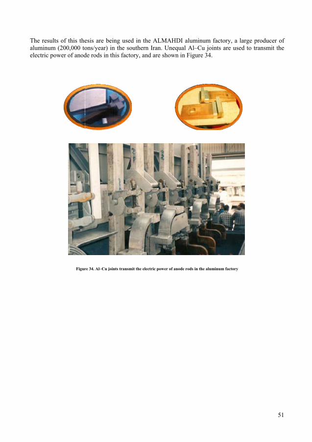
The resultsaluminum electric pow
s of this the(200,000 tower of anod
Figur
esis are beions/year) inde rods in th
re 34. Al–Cu join
ing used in n the southehis factory,
nts transmit the
the ALMAern Iran. Unand are sho
electric power o
AHDI aluminequal Al–Cown in Figur
of anode rods in
inum factorCu joints arre 34.
the aluminum fa
ry, a large pre used to t
factory
51
producer oftransmit the
f e

52
52
53
6. References 1. Experimental investigation of the mechanics of explosive welding by means of a liquid analogue. El-Sobky, H., Blazynski, T. Z. Colorado : Fifth International Conference on High Energy Rate Fabrication, 1975. Vol. 4. 2. B.Crossland. explosive welding of metals and its application. new york : oxford university press, 1982. 3. the Academy of Science. Ukraine : E.O. Paton Electric Welding Institute . 4. Darvizeh, A. Research notebooks. Iran : Gilan University. 5. Welding Handbook. 6. SME ; Handbook, Tool and Manufacturing Engineers. 1984. pp. 19-1. Vol. L. 7. Metals Handbook, Explosive welding. Vol. 6. 8. welding, Mechanism of wave formation at the interface in explosive. Chemin, C. and , No.2, ,. May 1989, ACTA Mechanica sinca, Vol. 5. 2. 9. Permissible rang of parameters for interface wave formation in explosive welding; India. Gupta, R.C and welding. India : s.n. 10. Binding criterion for metals with explosive welding combustion, Explosion and shock wave. Simonov, V.A. 1991. 11. Explosive welding status. Phillipchuk, V. 1961. ASTME Creative Manufacturing Seminar. pp. P65–100. 12. A. Williams, B. Crossland and J.D. Explosive welding. 1970. pp. 79–100. 13. Explosive cladding of large steel plates with lead. Carpente, H. Otto and S.H. 1973. Met. Mater. pp. 75–79. 14. Microstructure of explosively bonded interface between titanium and very low carbon steel as observed by TEM. Onzawa, T., Iiyama, T., Kobayashi, S., Takasaki, A., Ujimoto, Y. 1985. 15. Analytic solutions of liquid-drop impact problems. M.B. Lesser, , Proc. ., ), pp. . London : R. Soc, (1981. pp. 289–308. A 377 . 16. The geometric wave theory of liquid impact. Lesser, M.B., Field, J.E. 1983. Sixth International Conference on Erosion by Liquid and Solid Impact. 17. The impact of compressible liquids. Field, M.B. Lesser and J.E. 1983. Ann. Rev.Fluid Mech. Vol. 15, pp. 97–122. 18. Studies of two-dimensional liquid-wedge impact and their relevance to liquid-drop impact problems. J.E. Field, M.B. Lesser and J.P. Dear. s.l. : Proc. R. Soc. London A 401, 1985. pp. 225–249. 19. Wave formation between impacting liquids in explosive welding and erosion. Brunton, H.P.W. Wilson and J.H. s.l. : Nature, 1970, Vol. 226, pp. 534–538. 20. A discussion of the mechanism of interface wave generation in explosive welding. Reid, S.R. International, J. Mech. Sci. , 1974, Vol. 16, pp. 399–413. 21. Some observations on explosive cladding welding. Crossland, A.S. Bahrani and B. s.l. : Annual Conference AD, ASTME, 1966. pp. 66–112. 22. Experimental evidence of jet formation during explosion cladding. O.R. Bergman, G.R. Cowan and A.H. Holtzman. 1966. Trans. Metal Soc. AIME. pp. 646–653. 23. The mechanics of wave formation in explosive welding. A.S. Bahrani, T.J. Black and B. Crossland. 1966. Royal Soc. Ser. A 296. p. 123. 24. Permanent periodic surface deformations due to a travelling jet. Abrahamson, G.R. s.l. : J. Appl.Mech. , 1961, Vol. 83, pp. 519–528. 25. Wave formation in explosive welding. Hunt, .M. s.l. : J. Philos. Mag. , 1968, Vol. 17. 148. 26. A fluid model of impact welding. Robinson, J.L. s.l. : the Fifth International Conference on High Energy Rate Forming, 1975. 27. G.R. Cowan, O.R. Bergman and A.H. Holtzman. Mechanics of bond wave formation in explosive cladding of metals. s.l. : Metall. Trans. 2, 1971.

54
28. Hay, J.F. Kowalick and R.A. Mechanism of explosive welding. s.l. : Metall. Trans. 2, (1971. pp. 1953–1958. 29. Novelties in physics of explosive welding and powder compaction. I. Plaksin, J. Direito, D. Braga and R. Pruemme. s.l. : J. Phys., 2003, Vol. IV. 30. Solid mechanics approach explosive welding composite. Lazari, G.L., Al-Hassani, S.T.S. San Antonio : Eighth International Conference on High Energy Rate Fabrication, 1984. 31. Modeling of the explosive welding process. Oberg, J.A. Schweitz and H.C. Olfsson. 1984. Eighth International Conference on High Energy Rate Fabrication . pp. 75–84. 32. Numerical study of the mechanism of a wavy interface generation in explosive welding. Akihisa, A.B.E. s.l. s.l. : JSME, 1997. 33. Al-Hassani, S.T.S. Numerical and experimental investigation of explosive bonding process variables and their influence on bond strength. s.l. : University of Manchester Institute of Science and Technology (UMIST), 2001. GR/M10106/01. 34. Simulation of explosive welding using the Williamsburg equation of state to model low detonation velocity explosives. A.A. Akbari Mousavi, S.B. Burley and S.T.S. Al-Hassani. s.l. : Int. J.Impact Eng., 2005, pp. 719–734. 35. Finite element simulation of explosively-driven platenwith application to explosive welding. S.A.A. Akbari Mousavi, S.T.S. Al-Hassani. s.l. : materials, 2007. 36. Numerical and experimental studies of the mechanism of the wavy interface formations in explosive. Al-Hassani, A.A. Akbari Mousavi and S.T.S. s.l. : impact welding, 2005. 37. Automatic welding. USSR : s.n., 1994. 38. BUREAU. Experimental design. USSR : s.n., 1995. 39. RAVEN, Benson DJ . User's Manual. 2000. 40. COMSOL. Stochkolm,Sweden : s.n. version 3.3 a.
55
7. Papers summary Paper 1: An Applied Method for welding Metals of Unequal Surface Area Using Explosive Energy
The bond strength of explosive welding (BSEW) is very important in an explosive welding process. This paper describes studies on impact waves and designs an applied technique for removing the strength problem in the edges of Al-Cu welded plates to obtain a uniform welding. The results are validated by tensile experiments and SEM microscopy. This method is suggested for explosive welding in metals with unequal surface areas. Results of this research are applied in an aluminum company.
Paper 2: Removing Leakage from oil and gas low pressure Pipes and vessels by high energy explosive welding method
This research suggests a simple technique for removing leaks in metal pipes. This method is economical and easy to use for the maintenance of pipes and liquid vessels using explosive welding process. The results are tested by the usual methods. Paper 3: Effect of Explosive Layer Thickness on Detonation Velocity in a high energy process In this study the Dutrich method is used to measure the velocity of the explosion. This research shows a relationship between the thickness of the explosive layer and the detonation velocity. Above a certain thickness, the explosive velocity is constant. Derivation of this thickness is very important in an explosive process, because it determines the minimum thickness of explosive required to attain a constant velocity. At the end the paper a useful formula and some suggestions for explosive velocity experiments are presented, which may improve the reliability of the Dutrich method.