Embed Size (px)
Citation preview
Proceedings of the Cold-Formed Steel Research Consortium Colloquium20-22 October, 2020 (cfsrc.org)
Impact of Fastener Spacing on the Behavior of Cold-Formed Steel Shear Walls Sheathed withFiber Cement Board
Fani Derveni1, Simos Gerasimidis2, Kara D. Peterman3
Abstract
As cold-formed steel (CFS) is progressively used in high seismic regions as part of the designated lateral force resistingsystem, it is necessary to explore higher capacity systems. Furthermore, these systems must be fully enabled within relevantdesign specifications. The objective of this work is to provide design guidelines and performance benchmarks for cold-formed steel shear walls sheathed with fiber cement board (FCB). High-fidelity three-dimensional finite element modelingis introduced by investigating wall aspect ratio, and fastener spacing pattern. Herein, fasteners, which represent the criticalload path in CFS shear walls, are modelled via experimentally-derived phenomenological models. An experimental programof monotonic and cyclic connection testing is conducted aiming to shed light on the response of cold-formed steel to fibercement board sheathing connections. Connection backbone parameters are extracted from the experimental results andare implemented in the finite element model. As fastener spacing is decreased, failure mode shifts from fastener-dominantto the steel framing itself. This work aims to characterize this change in limit state and provide recommendations fordesign. Updates to AISI S400 are proposed, specifically in providing prescriptive design aids for the practicing engineer.Furthermore, the high-fidelity modeling approach expanded upon herein provides an analytical approach to explore theimpact of detailing on wall performance. Fiber cement board-sheathed shear walls represent a wealth of design potentialin increasing the lateral capacity available in cold-formed steel shear wall systems. This work provides the fundamentalbehavioral and limit state analysis towards eventual enabling within national specifications.
1. Introduction
Cold-formed steel (CFS) shear walls have been given sig-nificant attention due to the numerous benefits they offer asthe designated lateral force resisting systems in CFS con-struction. Economy, structural efficiency, prefabrication andtransportation ease are some of the aspects that make CFSan attractive component for research and design. CFS shearwalls sheathed with different materials (such as wood, steel,gypsum, cement) or braced by strap are of particular inter-est in high seismic regions and have been extensively ex-amined through experimental and computational methods inboth, small-scale (connections) and full-scale (shear walls)level.
Extensive connection testing between CFS members andsheathing has been conducted to understand the shear con-nection behavior under monotonic and/or cyclic loading. Ori-
1PhD Candidate, Department of Civil & Environmental Engineering, Uni-versity of Massachusetts Amherst, [email protected]
2Assistant Professor, Department of Civil & Environmental Engineering,University of Massachusetts Amherst, [email protected]
3Assistant Professor, Department of Civil & Environmental Engineering,University of Massachusetts Amherst, [email protected]
ented strand board (OSB) sheathing was examined by dif-ferent experimental programs ([1], [2], [3]), providing datafor shear connection capacities of different specimen char-acteristics (i.e. spacing or thickness). Steel sheathing, eithersteel sheet or corrugated steel sheet has also received ex-perimental attention ([4], [5]) via tests of single-screw speci-mens. Cement-based and gypsum-based sheathing to CFSconnections were also tested ([6], [7]), providing monotonicshear response for various materials and thicknesses.
Shear wall response has been the subject of numerous ex-perimental and modeling efforts to understand behavior, de-tail impact, and failure modes. OSB-sheathed shear wallsof different aspect ratios and wall characteristics were testedunder monotonic and cyclic loading ([8], [9], [10]) concludingfastener-governed failure mechanisms between CFS struc-tural frame and OSB sheathing. Steel sheathing is also ex-perimentally examined for steel sheet ([11], [12]) and corru-gated steel [13]. Cement-based, gypsum-based, and and/orcomposite sheathing materials have been increasingly ex-perimentally assessed in single- and/or double-sided walls([14], [15], [16]) since they offer higher lateral capacities andfire resistance benefits. Different shear wall computational

approaches have been conducted through fastener-basedmodeling. Performance-based models in OpenSees wereused for OSB-sheathed walls ([17], [18]), or steel-sheathedwalls [19] through Pinching4 connection model. High-fidelitymodeling efforts in Ansys were proposed for strap-basedwalls [20], as well as in Abaqus for OSB ([21], [22], [3]) andsteel sheathing [23] providing different methods for connec-tion simulation and response.
This study aims to shed light on the lateral behavior ofCFS shear walls sheathed with FCB by investigating theimpact of perimeter fastener spacing on strength, stiffnessand governing failure modes for these systems. Initially, theshear connection response is experimentally assessed, pro-viding monotonic and cyclic average test data for two differ-ent screw types. A fastener-based shear wall finite elementmodeling approach follows, presenting capacity predictionsand governing wall limit states (from fastener failures to CFSmember failures) implicit to fastener spacing. The main goalof this work is to provide design predictions for FCB-sheathedshear walls towards an effort of enabling the beneficial lateralbehavior of these systems within both, research communityand design specifications.
2. Shear connection experimental program
An experimental program composed of in total 12 specimensis conducted herein in order to obtain shear response of cold-formed steel (CFS) to fiber cement board (FCB) connections,and to extract data for shear wall computational modeling.The connections were tested under monotonic and cyclicloading.
The test rig and specimens, as adapted by [3], are illus-trated in Figure 1. The specimens are attached to the rigvia hot-rolled steel plates at both sides of stud webs in or-der to provide fixity of the webs against deformation and fo-cus the failure on the connections (exterior plates: 25.4mm(1in.) thick, interior plates: 12.7mm (0.5in.) thick). The toppart is subjected to tensile or cyclic loading, while the bottompart is fixed. The specimens are composed of: CFS studs(web: 152.4mm, flange: 41.3mm, lip: 12.7mm, thickness:1.37mm (600S162-54)), FCB sheathing (length: 304.8mm,width: 406.4mm, thickness: 19.05mm (12in. x 16in. x 3/4in.)and M4 (No. 8) screws (type “a”, type “b”). Two screws areexamined herein from which type “a” is used to representa new screw M4x50, and screw “b” is used to represent acommon industrial screw M4x40 (Figure 1c). Two differentsheathing screw configurations are examined herein: a) FCBand CFS connected with screw “a” (CFS-a-FCB), and b) FCBand CFS connected with screw “b” (CFS-b-FCB).
Monotonic loading is applied at a rate of 101.6mm/hour(4in./hour) after a pre-loading of 45kN (10lbs). Cyclic loadingis applied by defining the commonly used CUREE protocol,
Δ
304.8mm
Fixed
Screw "a"
Screw "b"
38.1mm
406.4mm
304.
8mm
FCB sheathing
Exteriorplates
Interiorplates
CFS studs
(a) (b) (c)
Figure 1: Shear connection test specimens and test rig. (a) Actual photoof test rig in Instron machine, (b) connection specimen schematic, and (c)screw types.
as described by [24]. The resultant cyclic protocol is shownin Figure 2 and it is based on a reference displacement (∆)defined in Equation 1:
∆ = 0.6∆m (1)
where ∆m is the displacement at 80% of the post-peak loadof the prior monotonic tests. The reference displacement∆ of CFS-a-FCB is equal to 7.61mm (0.3in.), while the ref-erence displacement ∆ of CFS-b-FCB is equal to 4.59mm(0.2in.).
Initiatoncycles
Primarycycles
Trailingcycles
CUREE Protocol
Figure 2: Resultant CUREE protocol for cyclic tests.
3. Experimental results
The test results for the CFS-a-FCB and CFS-b-FCB speci-mens are depicted in for both monotonic (Figure 3) and cyclicloading (Figure 4). The results show low variability in strengthand stiffness for all the repetitions of CFS-a-FCB specimens,while energy dissipation is higher in one of the cyclic repe-titions. For the CFS-b-FCB specimens significant strength
2

variability is illustrated in one of the monotonic repetitions,while strength, stiffness and energy dissipation is consistentwithin the remaining repetitions. Comparing the average re-sponses between CFS-a-FCB and CFS-b-FCB specimens(shown in Figures 3 and 4 with black lines), a percentagedifference of 3.7% and 15% results for monotonic and cyclictests, respectively. Secant stiffness is higher by 44% and71% for screw “b” in comparison to screw “a” for monotonicand cyclic tests, respectively.
a b
(a) (b)
Figure 3: Monotonic experimental results: (a) CFS-a-FCB identical spec-imens, (b) CFS-b-FCB identical specimens. Average data are extracted(black lines) based on 40%Peak, 80%Peak, 100%Peak, 30%Post-peakload.
The governing failure modes of the different tests are distin-guished between shear screw failure or screw pull-through,both followed by screw bearing and/or FCB sheathing edgetear out. Specifically, CFS-a-FCB monotonic repetitions pri-mary failed due to pull-through of the screws accompaniedby sheathing edge tear out and shear failure of some ofthe screws post-peak. For the CFS-b-FCB monotonic rep-etitions, shear failure of the screws governed the response,followed by screw bearing and/or sheathing edge tear outpost-peak. Tilting of the screws at the beginning of the testsoccurred at the beginning of all monotonic tests. For all cyclictest repetitions (CFS-a-FCB and CFS-b-FCB), shear screwfailure was the primary failure mechanism accompanied bylocalized bearing in the location of the screws.
(a) (b)
ba
Figure 4: Cyclic experimental results: (a) CFS-a-FCB identical specimens,(b) CFS-b-FCB identical specimens. Symmetric average data (minimumof positive and negative quadrant) are extracted (black lines) based on40%Peak, 80%Peak, 100%Peak, last point at lower drifts to represent re-alistic connection behavior.
The response of the system of eight screws is converted to
individual screw response via equations introduced by [1].The force per screw Pi is equal to Pi = P/4, the displace-ment per screw ∆i is equal to ∆i = ∆/2, and the stiffnessper screw Ki is equal to Ki = K/2, where P , ∆, K are thesystem force, system displacement, system stiffness respec-tively. Average individual screw behavior is shown in Table 1.
Table 1: Average backbone parameters for FCB connections
Average Backbone ParametersMonotonic tests Cyclic tests
FCB-a FCB-b FCB-a FCB-b∆1(mm)/P1(kN) 0.71 / 1.50 0.60 / 1.44 0.45 / 0.99 0.42 / 1.14∆2(mm)/P2(kN) 3.28 / 2.99 2.07 / 2.88 1.84 / 1.97 1.45 / 2.27∆3(mm)/P3(kN) 5.65 / 3.74 3.80 / 3.61 3.43 / 2.47 2.30 / 2.84∆4(mm)/P4(kN) 8.75 / 1.12 8.80 / 1.08 6.75 / 0.44 6.08 / 0.35
4. Shear wall finite element modeling
The computational method implemented here is a two-stageapproach introduced and validated by [3] for OSB-sheathedCFS shear walls and it is expanded herein upon FCB-sheathed shear walls. The two stages are defined as follows:
1. A linear elastic analysis by using a global coordinatesystem in all CFS-to-FCB connections for calculatingangles of axes rotation for all the connections.
2. A pushover analysis by implementing local coordinatesystems in all CFS-to-FCB connections for accuratelycapturing connection response.
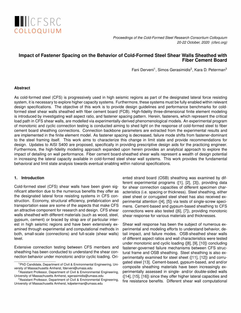
The shear wall configuration adopted herein is based on thetest rig of McGill University for OSB-sheathed walls [10], asshown in Figure 5a. A wall configuration of 1.22m x 2.44m(4ft x 8ft) is simulated (wall aspect ratio equal to 2) by investi-gating the impact of different fastener spacings on the lateralperformance of the wall. Four different perimeter fastenerspacings between CFS and FCB are selected: 152.4mm(6in.), 101.6mm (4in.), 76.2mm (3in.), 50.8mm (2in.), andthe different failure modes and limit states are numericallypredicted. The wall is constructed of:
• CFS studs (back-to-back chord and field) of a thicknessof 1.37mm (54mils), web depth of 92.08mm (3.62in.),flange width of 41.3mm (1.62in.), and lip depth of12.7mm (0.5in.).
• CFS tracks of a thickness of 1.37mm (54mils), webdepth of 92.08mm (3.62in.), and flange width of 30.2mm(1.19in.).
• FCB sheathing of a thickness of 19.05mm (0.75in.)
• M4 x 50 (No. 8) screw (type “a”) or M4 x 40 (No.8) screw(type “b”) for the connections between CFS membersand FCB sheathing.
• Simpson Strong-Tie S/HD10S hold-downs.
3
(a) (b)
2.44m
1.22m
FCB
CFS
Connector
element
1
2
z-Shear
x-Sheary-Pullout
CFS
CFS
Multi-point
constraint
Figure 5: FCB-sheathed CFS shear wall configuration. (a) Schematic rep-resentation of the wall. (b) Mesh of all simulated components.
All the simulated components (CFS and FCB) are modeledvia S4R shell elements in Abaqus. CFS components are dis-cretized through a finer mesh of 6.35mm (0.25in.) in compar-ison to FCB sheathing coarse mesh of 50.8mm (2in.). Figure5b shows the mesh size of the different components.
CFS components (studs and tracks) are simulated throughplastic isotropic material properties (Young’s modulus:E=203GPa (29500ksi), Yield strength: σy=344MPa (50ksi),Poisson’s ratio: ν=0.3), while FCB sheathing as elasticisotropic material (Young’s modulus: E=8963MPa (1300ksi),Poisson’s ratio: ν=0.3).
CFS-to-FCB connections are simulated through connectorelement Cartesian in Abaqus. Experimental monotonic aver-age data derived by the shear connection testing of the pre-vious section are used to represent the connection responsefor the two shear directions (Table 1). For the pull-out di-rection a high stiffness of 1750000kN/m (10000kips/in.) isused to restrain the sheathing out-of-plane movement. Fig-ure 5b indicates the connector element representation be-tween CFS and FCB and a representative coordinate sys-tem used herein. CFS-to-CFS connections are modeled viamulti-point pinned constraints (MPC pinned) in Abaqus by re-straining their translational degrees of freedom. Stud-to-trackconnections in the center of their flanges and stud-to-studconnections on the webs of chord studs spacing 304.8mm(12in.) are shown in Figure 5b.
At the bottom of the wall, shear anchors and hold-downs areused to restrain the shear wall lateral response. Four shearanchor nodes at the bottom track are used to restrain thehorizontal and the out-of-plane (x and y axes) wall direction,
while hold-downs are used to prevent the wall uplift throughrigid body simulation at the bottom chord-stud webs tied to areference point and connected to a fixed node via a Spring2element (Figure 5b). The hold-down in tension carries a stiff-ness of 22292kN/m (127.3kips/in.) and hold-down in com-pression carries 1000 times higher the stiffness of the tensilehold-down.
At the top of the wall, the out-of-plane (y axis) wall movementis restrained via a line of six nodes spacing 230mm (9in.) atthe top track. Loading is applied at a reference point at thecenter of the top track rigid body edge through displacementcontrol (displacement of 0.08m (3.15in.) is applied).
5. Finite element modeling results
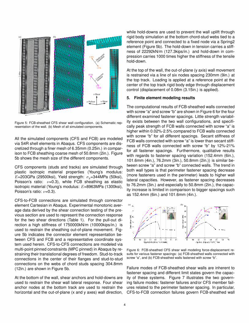
The computational results of FCB-sheathed walls connectedwith screw “a” and screw “b” are shown in Figure 6 for the fourdifferent examined fastener spacings. Little strength variabil-ity exists between the two wall configurations, and specifi-cally peak strength of FCB walls connected with screw “a” ishigher within 0.02%-2.5% compared to FCB walls connectedwith screw “b” for all different spacings. Secant stiffness ofFCB walls connected with screw “a” is lower than secant stiff-ness of FCB walls connected with screw “b” by 12%-21%for all fastener spacings. Furthermore, qualitative resultswith regards to fastener spacing variation (152.4mm (6in.),101.6mm (4in.), 76.2mm (3in.), 50.8mm (2in.)) is similar be-tween screw “a” and screw “b” connected walls. The trend inboth wall types is that perimeter fastener spacing decrease(more fasteners used in the perimeter) leads to higher walllateral capacities. However, as fastener spacing decreasesto 76.2mm (3in.) and especially to 50.8mm (2in.), the capac-ity increase is limited in comparison to bigger spacings suchas 152.4mm (6in.) and 101.6mm (4in.).
(a) (b)
a b
Figure 6: FCB-sheathed CFS shear wall modeling force-displacement re-sults for various fastener spacings: (a) FCB-sheathed walls connected withscrew “a”, and (b) FCB-sheathed walls fastened with screw “b”.
Failure modes of FCB-sheathed shear walls are inherent tofastener spacing and different limit states govern the capac-ity of these systems. Figure 7 illustrates the two govern-ing failure modes: fastener failures and/or CFS member fail-ures related to the perimeter fastener spacing. In particular,CFS-to-FCB connection failures govern FCB-sheathed wall
4
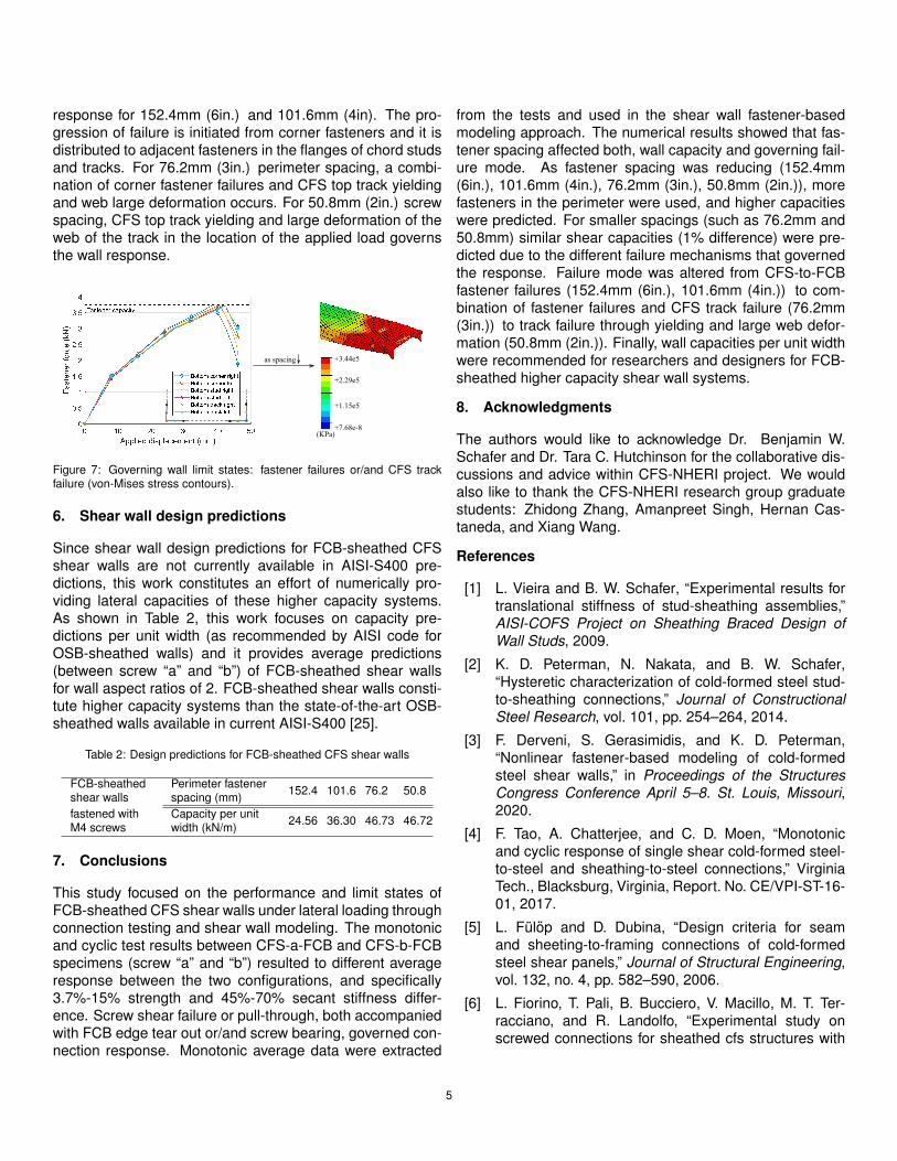
response for 152.4mm (6in.) and 101.6mm (4in). The pro-gression of failure is initiated from corner fasteners and it isdistributed to adjacent fasteners in the flanges of chord studsand tracks. For 76.2mm (3in.) perimeter spacing, a combi-nation of corner fastener failures and CFS top track yieldingand web large deformation occurs. For 50.8mm (2in.) screwspacing, CFS top track yielding and large deformation of theweb of the track in the location of the applied load governsthe wall response.
as spacing +3.44e5
+7.68e-8
+2.29e5
+1.15e5
(KPa)
Figure 7: Governing wall limit states: fastener failures or/and CFS trackfailure (von-Mises stress contours).
6. Shear wall design predictions
Since shear wall design predictions for FCB-sheathed CFSshear walls are not currently available in AISI-S400 pre-dictions, this work constitutes an effort of numerically pro-viding lateral capacities of these higher capacity systems.As shown in Table 2, this work focuses on capacity pre-dictions per unit width (as recommended by AISI code forOSB-sheathed walls) and it provides average predictions(between screw “a” and “b”) of FCB-sheathed shear wallsfor wall aspect ratios of 2. FCB-sheathed shear walls consti-tute higher capacity systems than the state-of-the-art OSB-sheathed walls available in current AISI-S400 [25].
Table 2: Design predictions for FCB-sheathed CFS shear walls
FCB-sheathed Perimeter fastener 152.4 101.6 76.2 50.8shear walls spacing (mm)fastened with Capacity per unit 24.56 36.30 46.73 46.72M4 screws width (kN/m)
7. Conclusions
This study focused on the performance and limit states ofFCB-sheathed CFS shear walls under lateral loading throughconnection testing and shear wall modeling. The monotonicand cyclic test results between CFS-a-FCB and CFS-b-FCBspecimens (screw “a” and “b”) resulted to different averageresponse between the two configurations, and specifically3.7%-15% strength and 45%-70% secant stiffness differ-ence. Screw shear failure or pull-through, both accompaniedwith FCB edge tear out or/and screw bearing, governed con-nection response. Monotonic average data were extracted
from the tests and used in the shear wall fastener-basedmodeling approach. The numerical results showed that fas-tener spacing affected both, wall capacity and governing fail-ure mode. As fastener spacing was reducing (152.4mm(6in.), 101.6mm (4in.), 76.2mm (3in.), 50.8mm (2in.)), morefasteners in the perimeter were used, and higher capacitieswere predicted. For smaller spacings (such as 76.2mm and50.8mm) similar shear capacities (1% difference) were pre-dicted due to the different failure mechanisms that governedthe response. Failure mode was altered from CFS-to-FCBfastener failures (152.4mm (6in.), 101.6mm (4in.)) to com-bination of fastener failures and CFS track failure (76.2mm(3in.)) to track failure through yielding and large web defor-mation (50.8mm (2in.)). Finally, wall capacities per unit widthwere recommended for researchers and designers for FCB-sheathed higher capacity shear wall systems.
8. Acknowledgments
The authors would like to acknowledge Dr. Benjamin W.Schafer and Dr. Tara C. Hutchinson for the collaborative dis-cussions and advice within CFS-NHERI project. We wouldalso like to thank the CFS-NHERI research group graduatestudents: Zhidong Zhang, Amanpreet Singh, Hernan Cas-taneda, and Xiang Wang.
References
[1] L. Vieira and B. W. Schafer, “Experimental results fortranslational stiffness of stud-sheathing assemblies,”AISI-COFS Project on Sheathing Braced Design ofWall Studs, 2009.
[2] K. D. Peterman, N. Nakata, and B. W. Schafer,“Hysteretic characterization of cold-formed steel stud-to-sheathing connections,” Journal of ConstructionalSteel Research, vol. 101, pp. 254–264, 2014.
[3] F. Derveni, S. Gerasimidis, and K. D. Peterman,“Nonlinear fastener-based modeling of cold-formedsteel shear walls,” in Proceedings of the StructuresCongress Conference April 5–8. St. Louis, Missouri,2020.
[4] F. Tao, A. Chatterjee, and C. D. Moen, “Monotonicand cyclic response of single shear cold-formed steel-to-steel and sheathing-to-steel connections,” VirginiaTech., Blacksburg, Virginia, Report. No. CE/VPI-ST-16-01, 2017.
[5] L. Fulop and D. Dubina, “Design criteria for seamand sheeting-to-framing connections of cold-formedsteel shear panels,” Journal of Structural Engineering,vol. 132, no. 4, pp. 582–590, 2006.
[6] L. Fiorino, T. Pali, B. Bucciero, V. Macillo, M. T. Ter-racciano, and R. Landolfo, “Experimental study onscrewed connections for sheathed cfs structures with
5

gypsum or cement based panels,” Thin-Walled Struc-tures, vol. 116, pp. 234–249, 2017.
[7] S. Selvaraj and M. Madhavan, “Investigation onsheathing-fastener connection failures in cold-formedsteel wall panels,” in Structures, Elsevier, vol. 20, 2019,pp. 176–188.
[8] R. L. Serrette, J. Encalada, M. Juadines, and H.Nguyen, “Static racking behavior of plywood, osb, gyp-sum, and fiberbond walls with metal framing,” Journalof Structural Engineering, vol. 123, no. 8, pp. 1079–1086, 1997.
[9] P. Liu, K. D. Peterman, and B. W. Schafer, “Impact ofconstruction details on osb-sheathed cold-formed steelframed shear walls,” Journal of Constructional SteelResearch, vol. 101, pp. 114–123, 2014.
[10] A. E. Branston, C. Y. Chen, F. A. Boudreault, and C. A.Rogers, “Testing of light-gauge steel-frame - woodstructural panel shear walls.,” Canadian Journal of CivilEngineering, vol. 33, no. 5, pp. 561–572, 2006, ISSN:03151468.
[11] C. Yu, H. Vora, T. Dainard, J. Tucker, and P. Veetvkuri,“Steel sheet sheathing options for cold-formed steelframed shear wall assemblies providing shear resis-tance,” University of North Texas, Denton, Texas, USA,Report. No. UNT-G76234, 2007.
[12] J. DaBreo, N. Balh, C. Ong-Tone, and C. Rogers,“Steel sheathed cold-formed steel framed shear wallssubjected to lateral and gravity loading,” Thin-WalledStructures, vol. 74, pp. 232–245, 2014.
[13] L. Fulop and D. Dubina, “Performance of wall-studcold-formed shear panels under monotonic and cyclicloading: Part i: Experimental research,” Thin-WalledStructures, vol. 42, no. 2, pp. 321–338, 2004.
[14] S. Mohebbi, S. R. Mirghaderi, F. Farahbod, A. B. Sab-bagh, and S. Torabian, “Experiments on seismic be-haviour of steel sheathed cold-formed steel shear wallscladded by gypsum and fiber cement boards,” Thin-Walled Structures, vol. 104, pp. 238–247, 2016.
[15] M. S. Hoehler, C. M. Smith, T. C. Hutchinson, X. Wang,B. J. Meacham, and P. Kamath, “Behavior of steel-sheathed shear walls subjected to seismic and fireloads,” Fire safety journal, vol. 91, pp. 524–531, 2017.
[16] M. Zeynalian and H. R. Ronagh, “Seismic performanceof cold formed steel walls sheathed by fibre-cementboard panels,” Journal of Constructional Steel Re-search, vol. 107, pp. 1–11, 2015.
[17] S. Buonopane, G. Bian, T. Tun, and B. Schafer, “Com-putationally efficient fastener-based models of cold-formed steel shear walls with wood sheathing,” Journalof Constructional Steel Research, vol. 110, pp. 137–148, 2015.
[18] S. Kechidi and N. Bourahla, “Deteriorating hysteresismodel for cold-formed steel shear wall panel basedon its physical and mechanical characteristics,” Thin-Walled Structures, vol. 98, pp. 421–430, 2016.
[19] A. Singh and T. C. Hutchinson, “Finite element model-ing and validation of steel-sheathed cold-formed steelframed shear walls,” in Proceedings of the InternationalSpecialty Conference on Cold-Formed Steel Struc-tures. St. Louis, Missouri, 2018.
[20] M. Zeynalian and H. R. Ronagh, “A numerical study onseismic performance of strap-braced cold-formed steelshear walls,” Thin-walled structures, vol. 60, pp. 229–238, 2012.
[21] H. H. Ngo, “Numerical and experimental studies ofwood sheathed cold-formed steel framed shear walls,”M.S. thesis, Johns Hopkins University, Baltimore, MD,2014.
[22] C. Ding, “Monotonic and cyclic simulation of screw-fastened connections for cold-formed steel framing,”M.S. thesis, Virginia Tech, Blacksburg, VA, 2015.
[23] Z. Zhang and B. W. Schafer, “Simulation of steel sheetsheathed cold-formed steel framed shear walls,” inProceedings of the Annual Proceedings of the An-nual Stability Conference Structural Stability ResearchCouncil April 2–5. St. Louis, Missouri, 2019.
[24] H. Krawinkler, F. Parisi, L. Ibarra, A. Ayoub, and R.Medina, “Development of a testing protocol for woodframe structures, curee publication no,” W-02, Califor-nia, 2000.
[25] AISI-S400-15, “North american standard for seismicdesign of cold-formed steel structural systems,” in AISI-S400, Washington, D.C.: American Iron and Steel Insti-tute, 2015.
6