Embed Size (px)
Citation preview

Indian Journal of Fibre & Textile Research
Vol. 33, December 2008, pp. 451-467
Review Article
Impact of different stages of spinning process on fibre orientation and
properties of ring, rotor and air-jet yarns: Part 1– Measurements of
fibre orientation parameters and effect of preparatory processes on
fibre orientation and properties
Akshay Kumar, S M Ishtiaquea & K R Salhotra
Department of Textile Technology, Indian Institute of Technology, New Delhi 110 016, India
and
M S Senthil Kannan
Department of Textile Technology, PSG College of Technology, Peelamedu,
Coimbatore 641 004, India
Received 11 June 2007; revised received and accepted 25 March 2008
The economic situation of the textile industry and the extremely sharp worldwide competition have forced the textile
mills to use all possibilities of cutting costs. In this context, the question of higher production at each spinning sequence of
machine gains importance. This demands a detailed study on the effect of spinning process variables on fibre orientation and
properties of products produced out of these machines. This paper reports a glimpse on the different measurement
techniques of fibre orientation parameters and impact of various preparatory processes on fibre orientation and properties.
Keywords: Drafting wave, Fibre extent, Fibre orientation, Fibrogram, Lindsley technique
IPC Code: Int. Cl.8 D02G3/00
1 Introduction
Since last 60 years, numerous concepts have been
introduced to characterize fibre orientation, namely
straightness, fibre extent, helix angle, coefficient of
relative fibre parallelization, proportion of curved
fibre ends, migration parameters, etc. Several methods
of investigating fibre orientation have been
developed, such as the direct method1 in which tracer
fibres are viewed through a projection microscope and
the indirect method2-4
, such as Lindsley2 and modified
Lindsley3 method in which the orientation and
parallelization in sliver and roving are quantified in
terms of weight ratios. The orientation parameters
measured with the direct method take into account the
behaviour of a single fibre and extrapolate the
characteristics of sliver or roving or yarn from it,
which is, infact, not a realistic measure. This is due to
the fact that the fibrous assembly contains a larger
number of fibres whose laying and overlapping each
other is of greater significance. Furthermore, both
these methods are quite old and need a thorough
review or modifications. This paper reports different
measurement techniques of fibre orientation
parameters and impact of various preparatory
processes on fibre orientation and properties.
2 Measurement of Fibre Orientation
The earliest method for the study of fibre
orientation was direct method, which was based on
the use of optical tracer fibre technique and ultraviolet
rays for the study of hooks. In optical tracer fibre
technique1,5
, 0.1–0.3% of tracer fibres are dyed with
any dark colour dye. These tracer fibres are further
mixed with parent fibres preferably during fibre
mixing just before blowroom opening. Further, in
optical tracer fibre technique the sliver, roving or yarn
is immersed in a solution, which is having same
refractive index as of parent fibres. This makes the
grey parent fibres to optically dissolve while profile
of coloured tracer fibres can easily be seen under a
microscope. The optical tracer fibre technique can be
used for the measurement of fibre orientation
parameters, like fibre extent, type of hooks and hook
________________ aTo whom all the correspondence should be addressed.
E-mail: [email protected]
INDIAN J. FIBRE TEXT. RES., DECEMBER 2008
452
extent in sliver, roving and yarn. The schematic view
of a fibre seen under microscope for the extent study
is shown in Fig. 1. But, this technique is very tedious
and time consuming. As the parameters like fibre
extent and hook extent are dependent on the length of
fibre used, these parameters cannot be compared in
different samples prepared from different fibre
lengths.
Further, the study of fibre overlap is a recent
approach to investigate the longitudinal behaviour of
fibre in yarn. It was measured in terms of two newly
proposed parameters, viz. fibre-overlap index (FOI)
and fibre-pair-overlap length (FPO). The objective of
measuring fibre-overlap indices was to get a direct
interpretation of total contact length between the
fibres which has earlier been interpreted from the
fibre extent.6
However, in the UV tracer fibre technique the
fibres are dyed with any commercial fluorescent dye
and this technique can only be used to study the fibre
orientation in the web delivered by the card,
drawframe and intermediate frame after collecting the
web on the black boards. In both of the above
techniques, the dyeing of fibres changes the surface
characteristics of the fibres. These fibres are thus
expected to behave differently during processing in
the spinning process. Further, both of them are quite
old. Recently, a new index named fibre straightness
index (FSI), which can give information about fibre
straightness and is comparable for different samples
made from different fibre types and lengths, is also
being used. FSI is a ratio of total axial projected
length of a fibre to the actual length of that fibre in a
section of length observed directly with the
microscope.6
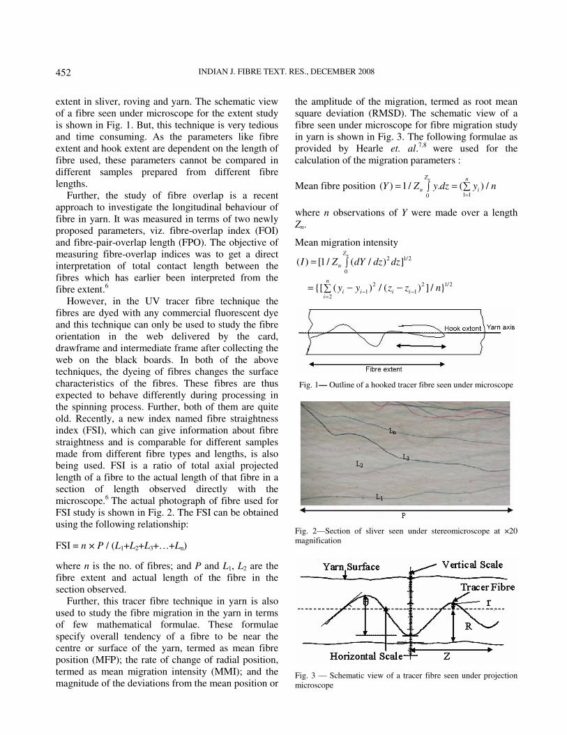
The actual photograph of fibre used for
FSI study is shown in Fig. 2. The FSI can be obtained
using the following relationship:
FSI = n × P / (L1+L2+L3+…+Ln)
where n is the no. of fibres; and P and L1, L2 are the
fibre extent and actual length of the fibre in the
section observed.
Further, this tracer fibre technique in yarn is also
used to study the fibre migration in the yarn in terms
of few mathematical formulae. These formulae
specify overall tendency of a fibre to be near the
centre or surface of the yarn, termed as mean fibre
position (MFP); the rate of change of radial position,
termed as mean migration intensity (MMI); and the
magnitude of the deviations from the mean position or
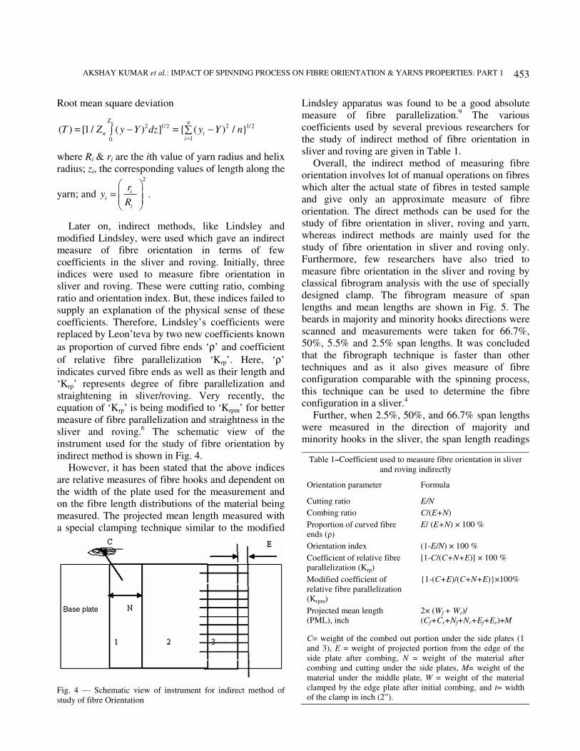
the amplitude of the migration, termed as root mean
square deviation (RMSD). The schematic view of a
fibre seen under microscope for fibre migration study
in yarn is shown in Fig. 3. The following formulae as
provided by Hearle et. al.7,8
were used for the
calculation of the migration parameters :
Mean fibre position 1 10
( ) 1 / . ( ) /nZ n
n iY Z y dz y n=
= = ∑∫
where n observations of Y were made over a length
Zn.
Mean migration intensity
2 1/2
0
( ) [1 / ( / ) ]nZ
nI Z dY dz dz= ∫
2 2 1/2
1 12
{[ ( ) / ( ) ] / }n
i i i ii
y y z z n− −
=
= − −∑
Fig. 1— Outline of a hooked tracer fibre seen under microscope
Fig. 2—Section of sliver seen under stereomicroscope at ×20
magnification
Fig. 3 — Schematic view of a tracer fibre seen under projection
microscope
AKSHAY KUMAR et al.: IMPACT OF SPINNING PROCESS ON FIBRE ORIENTATION & YARNS PROPERTIES: PART 1
453
Root mean square deviation
2 1/2 2 1/2
10
( ) [1 / ( ) ] { ( ) / }nZ n
n ii
T Z y Y dz y Y n=
= − = −∑∫
where Ri & ri are the ith value of yarn radius and helix
radius; zi, the corresponding values of length along the
yarn; and
2
i
i
i
ry
R
=
.
Later on, indirect methods, like Lindsley and
modified Lindsley, were used which gave an indirect
measure of fibre orientation in terms of few
coefficients in the sliver and roving. Initially, three
indices were used to measure fibre orientation in
sliver and roving. These were cutting ratio, combing
ratio and orientation index. But, these indices failed to
supply an explanation of the physical sense of these
coefficients. Therefore, Lindsley’s coefficients were
replaced by Leon’teva by two new coefficients known
as proportion of curved fibre ends ‘ρ’ and coefficient
of relative fibre parallelization ‘Krp’. Here, ‘ρ’
indicates curved fibre ends as well as their length and
‘Krp’ represents degree of fibre parallelization and
straightening in sliver/roving. Very recently, the
equation of ‘Krp’ is being modified to ‘Krpm’ for better
measure of fibre parallelization and straightness in the
sliver and roving.6 The schematic view of the
instrument used for the study of fibre orientation by
indirect method is shown in Fig. 4.
However, it has been stated that the above indices
are relative measures of fibre hooks and dependent on
the width of the plate used for the measurement and
on the fibre length distributions of the material being
measured. The projected mean length measured with
a special clamping technique similar to the modified
Lindsley apparatus was found to be a good absolute
measure of fibre parallelization.9 The various
coefficients used by several previous researchers for
the study of indirect method of fibre orientation in
sliver and roving are given in Table 1.
Overall, the indirect method of measuring fibre
orientation involves lot of manual operations on fibres
which alter the actual state of fibres in tested sample
and give only an approximate measure of fibre
orientation. The direct methods can be used for the
study of fibre orientation in sliver, roving and yarn,
whereas indirect methods are mainly used for the
study of fibre orientation in sliver and roving only.
Furthermore, few researchers have also tried to
measure fibre orientation in the sliver and roving by
classical fibrogram analysis with the use of specially
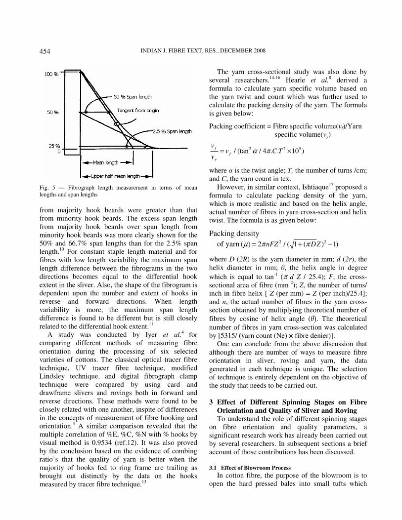
designed clamp. The fibrogram measure of span
lengths and mean lengths are shown in Fig. 5. The
beards in majority and minority hooks directions were
scanned and measurements were taken for 66.7%,
50%, 5.5% and 2.5% span lengths. It was concluded
that the fibrograph technique is faster than other
techniques and as it also gives measure of fibre
configuration comparable with the spinning process,
this technique can be used to determine the fibre
configuration in a sliver.4
Further, when 2.5%, 50%, and 66.7% span lengths
were measured in the direction of majority and
minority hooks in the sliver, the span length readings
Fig. 4 — Schematic view of instrument for indirect method of
study of fibre Orientation
Table 1–Coefficient used to measure fibre orientation in sliver
and roving indirectly
Orientation parameter Formula
Cutting ratio E/N
Combing ratio C/(E+N)
Proportion of curved fibre
ends (ρ)
E/ (E+N) × 100 %
Orientation index (1-E/N) × 100 %
Coefficient of relative fibre
parallelization (Krp)
[1-C/(C+N+E)] × 100 %
Modified coefficient of
relative fibre parallelization
(Krpm)
{1-(C+E)/(C+N+E)}×100%
Projected mean length
(PML), inch
2× (Wf + Wr)/
(Cf+Cr+Nf+Nr+Ef+Er)+M
C= weight of the combed out portion under the side plates (1
and 3), E = weight of projected portion from the edge of the
side plate after combing, N = weight of the material after
combing and cutting under the side plates, M= weight of the
material under the middle plate, W = weight of the material
clamped by the edge plate after initial combing, and t= width
of the clamp in inch (2”).
INDIAN J. FIBRE TEXT. RES., DECEMBER 2008
454
from majority hook beards were greater than that
from minority hook beards. The excess span length
from majority hook beards over span length from
minority hook beards was more clearly shown for the
50% and 66.7% span lengths than for the 2.5% span
length.10
For constant staple length material and for
fibres with low length variability the maximum span
length difference between the fibrograms in the two
directions becomes equal to the differential hook
extent in the sliver. Also, the shape of the fibrogram is
dependent upon the number and extent of hooks in
reverse and forward directions. When length
variability is more, the maximum span length
difference is found to be different but is still closely
related to the differential hook extent.11
A study was conducted by Iyer et al.4
for
comparing different methods of measuring fibre
orientation during the processing of six selected
varieties of cottons. The classical optical tracer fibre
technique, UV tracer fibre technique, modified
Lindsley technique, and digital fibrograph clamp
technique were compared by using card and
drawframe slivers and rovings both in forward and
reverse directions. These methods were found to be
closely related with one another, inspite of differences
in the concepts of measurement of fibre hooking and
orientation.4 A similar comparison revealed that the
multiple correlation of %E, %C, %N with % hooks by
visual method is 0.9534 (ref.12). It was also proved
by the conclusion based on the evidence of combing
ratio’s that the quality of yarn is better when the
majority of hooks fed to ring frame are trailing as
brought out distinctly by the data on the hooks
measured by tracer fibre technique.13
The yarn cross-sectional study was also done by
several researchers.14-16
Hearle et al.8 derived a
formula to calculate yarn specific volume based on
the yarn twist and count which was further used to
calculate the packing density of the yarn. The formula
is given below:
Packing coefficient = Fibre specific volume(vf)/Yarn
specific volume(vy)
2 2 5/ (tan / 4 . . 10 )f
f
y
vv C T
vα π= ×
where α is the twist angle; T, the number of turns /cm;
and C, the yarn count in tex.
However, in similar context, Ishtiaque17
proposed a
formula to calculate packing density of the yarn,
which is more realistic and based on the helix angle,
actual number of fibres in yarn cross-section and helix
twist. The formula is as given below:
Packing density
of yarn 2 2( ) 2 / ( 1 ( ) 1)nFZ DZµ π π= + −
where D (2R) is the yarn diameter in mm; d (2r), the
helix diameter in mm; θ, the helix angle in degree
which is equal to tan-1
(π d Z / 25.4); F, the cross-
sectional area of fibre (mm 2); Z, the number of turns/
inch in fibre helix [ Z (per mm) = Z (per inch)/25.4];
and n, the actual number of fibres in the yarn cross-
section obtained by multiplying theoretical number of
fibres by cosine of helix angle (θ). The theoretical
number of fibres in yarn cross-section was calculated
by [5315/ (yarn count (Ne) × fibre denier)].
One can conclude from the above discussion that
although there are number of ways to measure fibre
orientation in sliver, roving and yarn, the data
generated in each technique is unique. The selection
of technique is entirely dependent on the objective of
the study that needs to be carried out.
3 Effect of Different Spinning Stages on Fibre
Orientation and Quality of Sliver and Roving To understand the role of different spinning stages
on fibre orientation and quality parameters, a
significant research work has already been carried out
by several researchers. In subsequent sections a brief
account of those contributions has been discussed.
3.1 Effect of Blowroom Process
In cotton fibre, the purpose of the blowroom is to
open the hard pressed bales into small tufts which
Fig. 5 — Fibrograph length measurement in terms of mean
lengths and span lengths
AKSHAY KUMAR et al.: IMPACT OF SPINNING PROCESS ON FIBRE ORIENTATION & YARNS PROPERTIES: PART 1
455
provide new surface for cleaning the material.
However in man-mades, the blowroom is mainly
responsible for the efficient opening of compact fibre
mass in the bale form so that it can be processed
smoothly on subsequent process stages. The efficient
opening at blowroom stage not only improves fibre
cleaning but also improves yarn properties, like yarn
tenacity and total imperfections. However, with
excessive fibre openness these parameters deteriorate
sharply. The increase in imperfections at higher
openness is due to over beating than that which is
necessary, the fibres are stressed and damaged which
then buckle and tend to form neps. The changes in
fibre openness at blowroom do not appreciably
influence the yarn irregularity. The yarn hairiness
remains almost unchanged initially with the increase
in openness at blowroom, but at higher level of
openness it increases sharply. This is attributed to the
overstressing of fibres at high values of openness with
staple shortening and generation of short fibres. These
short fibres could be the cause of increase in hairiness
in yarn.18- 20
However, in a normal range of blowroom
treatment the degree of opening in the blowroom
greatly affects the cleaning and lint loss at carding.
But it does not appear to have a significant effect on
yarn quality and, in particular, on yarn strength,
evenness and performance.21
A high degree of
opening out in the blowroom reduces shortening of
staple at the cards.22
Furthermore, the opening of
fibres in the blowroom is essential to properly carry
out the subsequent process of carding for fibre
individualization, which, in turn, is essential for
smooth drafting at the drawframe, roving frame and
ring frame. Thorough opening of fibres is also
essential for achieving a homogenous blend at the
yarn stage.23
Also, the operation of blowroom needs
to be controlled depending upon the quality charac-
teristics desired in yarn. Further, the consistency in
yarn count depends on the degree of mixing or
uniformity of the lap or batt produced.20
The opening at blowroom is primarily dependent
on linear density of the lap processed. The reduction
in throughput rate/or thickness of the feed material to
any machines improves the opening capability of that
machine.20
The heavier lap causes excessive beating
at the card causing lap-ups in the card cylinder and
formation of too many neps. 23
However, a good
quality of sliver can be produced from a heavy lap by
using high draft at card.24
Further, the fibre
parallelization is always high, initially when the
heavier lap is fed to the card. This is due to more
carding force generated on the heavy fibre layer
present on the cylinder. But, final yarn quality in
terms of evenness and hairiness deteriorates.6
Overall the blowroom machine has influence on
the opening, blending, cleaning, parallelization and
distribution of the mass in the subsequent products,
like sliver, roving and yarn, which, in turn, influences
the quality of the final yarn also.25,26
3.2 Effect of Carding Process
Carding is the most important process responsible
for fibre individualization and straightness, which, in
turn, affects the fibre orientation in sliver, roving and
yarn. Several researchers have studied the effect of
carding process parameters on fibre orientation and
quality of sliver, roving and yarn. Carding is the first
process where fibre hooks are formed. The type of
hooks and their amount play a vital role in deciding
the fibre orientation and properties of sliver, roving
and yarn and their properties. The majority of fibres
are hooked at one or both ends in the card sliver, and
fibres having their trailing end hooked are dominant.
The leading hooks are not only fewer in number than
the trailing hooks, but also they are appreciably
smaller.5 Initially, the configurations of fibres are
classified in five groups, namely (i) fibres whose
leading ends are hooked, (ii) fibres whose trailing
ends are hooked, (iii) fibres with both ends are
hooked, (iv) fibres of which neither end is hooked but
are not necessarily straight, and (v) fibres which
assumed any other shape unclassifiable under the
groups (i)-(iv), i.e. knotted fibres, looped fibres, etc.1
Further, the mechanism of these different types of
hook formation was classified accordingly. Basically,
the fibres on the cylinder remain in two positions,
namely (a) those which are held in the position by
their leading end being hooked round the cylinder
wires, and (b) those which are not hooked around the
cylinder wires but held in position with the contact
and entanglement with the hooked fibres. Further
when type (a) reaches the doffer, transfer takes place
with relatively straight trailing ends lashed into the
doffer wire point more firmly than the hooked end is
held by the cylinder. Otherwise, the fibres would be
drawn past the doffer, merely having their tails
brushed once again. The probability of such effective
lashing into the doffer wire, however, seems to be
very remote. The class (b) type of fibres on reaching
the doffer will be arrested at its projecting part most
probably by actual contact with a doffer wire. The rest
INDIAN J. FIBRE TEXT. RES., DECEMBER 2008
456
of its length will immediately swept downwards by
the rapidly rotating cylinder forming a trailing hook
by carding its leading end. Thus, the above two types
of fibre transfer in carding lead to majority of hooks
in carding sliver as a trailing hook. The third group of
the hooks may be formed in card sliver possibly due
to three mechanisms. Firstly, the downward trailing
ends of the fibre immediately below the doffer setting
point may have their extremities slipped in to the form
of a hook by the rapid passage of the cylinder wires.
Second possibility is that the hooking of the leading
ends is accomplished at the doffer comb. The majority
of the fibres on the doffer may approach the doffer
comb with relatively straightened ends projecting
forward and with its downward stroke be bent
forward to form hook. Thirdly, the leading hooked
ends at cylinder immediately after leaving the flats, if
they are held loosely on cylinder surface, may
dislodge from the cylinder under the influence of air
current especially below the bottom edge of the front
plate. These fibres after dislodging from the cylinder
approaches to the doffer with hooked ends leading
and lying close to the cylinder surface though
detached from it. Such leading ends conceivably
passed intact through cylinder and doffer.1 Overall, it
was observed that the majority of fibres change their
configuration during transfer. Hooks are formed and
previously formed hooks are removed. Transfer of
fibres takes place both with and without reversal of
ends. The fibres that are transferred without reversal
change their configurations more. Thus, the number
or the percentage of leading and trailing hooks in the
web depends on the balance of three factors, namely
(a) number of fibres with hooks transferred from the
cylinder to the doffer with or without reversal; (b)
number of straight ends hooked during transfer and
then transferred with or without reversal; and (c)
number of hooked ends straightened out due to
carding action between the cylinder and the doffer.
Further, the magnitudes of (a), (b) and (c) factors and
hence the number of hooks are likely to be influenced
by fibre, process and machine factors.
Further, an increase in load on the operational layer
of the cylinder would decrease the magnitude of
positive control that cylinder wires have over
individual fibres. In such a state, fibre transfer will
take place more easily without reversal, leaving the
leading hooks as leading hooks on the doffer surface.
It was also postulated that the formation of a leading
hook on the doffer during transference is caused by
buckling of the front end of a fibre. When the front
end of a fibre moving with the velocity of the cylinder
comes in contact with the relatively slower moving
doffer surface, it buckles, and if the fibre is loosely
held by the cylinder, it gets transferred without
reversal. When conditions for buckling of front ends
are satisfied, the probability of a fibre transferring
from the cylinder to the doffer without reversal of
ends would depend largely on the nature and extent of
positive control exercised by the cylinder on the rest
of the fibre.27
Quantitatively, in card sliver 50% are
trailing hooks, about 15% are leading hooks, about
15% are double hooks, and less than 20% of fibres are
not hooked at all. 22
Further, several researchers have studied the effect
of carding process parameters on fibre orientation and
quality of sliver, roving and yarn. There are various
processing factors affecting the quality of carding
operation. The effects of these factors are described
briefly in next few sections.
3.2.1 Influence of Card Sliver Weight
The sliver weight is changed either by changing
linear density of lap feed for constant card draft or by
changing card draft for a constant linear density of
lap. The nature of change in the orientation of fibres
in sliver shows that the increase in sliver weight,
either through lap hank or through card draft,
decreases the proportion of curved fibre ends and
increases relative coefficient of fibre parallelization
and projected mean length. This was explained on the
basis of deposition of operational layers over cylinder.
As coarse lap is fed or card draft is reduced, the
operational layers on the cylinder increases, which
results in increase in the carding force due to the
increased inter-fibre friction. This ultimately increases
the fibre straightening and decreases the proportion of
curved fibre ends.24
Furthermore, the cylinder-to-doffer fibre transfer
decreases and cylinder load increases as sliver weight
is decreased. At low carding rate, increased sliver
weight caused smaller increase in majority hooks
(trailing) but definite decrease in minority hooks
(leading). Overall projected mean length decreases
with the increase in sliver weight. Card web neps and
yarn imperfections increase with the increase in
carding rate. At lower carding rate, sliver weight has
little effect on card web neps. However, at higher
carding rate the coarse sliver appears to have fewer
neps. Although the trend was not consistent, this
could indicate a direct relationship between neps and
AKSHAY KUMAR et al.: IMPACT OF SPINNING PROCESS ON FIBRE ORIENTATION & YARNS PROPERTIES: PART 1
457
minority hooks. Since the heavy weight sliver had
fewer minority hooks than the light weight sliver at
high carding rate, the yarn imperfections increase
with the increase in sliver weight. Also, the increased
draft necessary to process a heavy weight sliver
relative to the light weight sliver into the same size
yarn caused yarn imperfections to increase. The
higher carding rates also improve fibre orientation,
which offset the increased short term variability of the
card sliver and improves drafting, resulting in a more
uniform second drawing sliver. Sliver weight and
carding rate had little effect on the yarn uniformity.
Overall, as the carding rate increases the strength and
elongation decrease marginally. Also, yarn grade
deteriorates with the increase in sliver weight and
carding rate.24, 28-31
End breakage rates may increase
with the increase in sliver weight. 31
Furthermore, it was also reported that both fibre
parallelization and fibre hooks decrease as card sliver
weight increases, indicating that there are less total
hooks in the heavy weight sliver than in the light
weight sliver, even though the fibres in the former are
less parallel than in the later.32
3.2.2 Influence of Doffer Speed
A study conducted in Japan shows that at higher
card production rate the leading fibre hooks in the
sliver increase and the fibre arrangements in sliver
change. A distinct rise in the number of leading hooks
at higher production rates can be seen, because of the
reduced peripheral speed ratio of cylinder and doffer.
The number of reverse hooks decreases as the
production rate increases, because of the higher
tension drafts. Thus, high performance carding affects
not only the carding quality but also the yarn
quality.33
Similarly, bad carding, where cylinder speed is
reduced and doffer speed is increased from the
normal, gives better parallelization, but the rate of
improvement in parallelization in the subsequent
processes is better with good carding, probably due to
better fibre separation. Fibre separation seems to
influence carding quality more than the fibre
parallelization. Open end spinning has been found to
be more sensitive to carding condition both for
performance and yarn quality as compared to ring
spinning. The measurement of hooks and fibre
parallelization in card, drawing slivers and roving
showed that the projected mean length (PML) of
fibres in sliver and roving, which measure the degree
of parallelization of fibres, was higher under bad
carding condition at all the stages. The values of
PML with bad carding were much higher than those
with good carding at card stage and subsequently as
the sliver was processed through drawing and roving.
This difference in PML at card stage due to carding
condition gets narrowed down as the rate of
improvement of parallelization in the subsequent
process was high with good carding, possibly due
to better fibre-to-fibre separation and degree of
parallelization obtained with good carding.
However, the difference in PML never vanishes
completely even up to roving.34
Furthermore, with
the bad carding conditions the effect of increased
relative speed of doffer causes reduction in majority
hooks and increase in minority hooks at the card
stage. Majority hooks are more under good carding
at the card stage and this trend continues up to first
and second drawing stages. Similarly, minority
hooks are more under bad carding than with good
carding condition at card stage and this trend
continues up to first and second drawing. This
indicates that the rate of unhooking the hooked fibre
during drafting at drawing remains same, irrespective
of the carding condition under which hooks are
formed.34
Further, the removal of neps at carding stage
significantly improves with the reduction in card
production rate because of the intensive carding
action. At higher card production rate, neps level
tends to increase further at the drawing. Inferior
quality of carding at the higher card production rate
may be responsible for the generation of neps at
drawing. Better carding quality at lower card
production rate improves the yarn tenacity.35
However, an increase in card production rate
increases the neps in the sliver mainly due to inferior
carding quality at higher production rate. But, the
number of drawframe passage after carding does not
influence neps generation. Thick places and neps in
ring yarn increase with the increase in card production
rate. The yarn unevenness (U %), however, increases
marginally with the increase in card production rate.36
The above discussion reveals that the decrease in
the card draft and production rate not necessarily
improves fibre orientation parameters in the sliver but
definitely improves the yarn properties. Apart from
deciding the quality parameters at various subsequent
stages the carding process also significantly affects
the fibre orientation in sliver and roving.
INDIAN J. FIBRE TEXT. RES., DECEMBER 2008
458
3.2.3 Carding Force
In carding operation, the force required to
individualize a tuft at cylinder-flat zone is called
carding force. Increase in the load on the operational
layer of the cylinder at a constant cylinder speed
linearly increases the carding force. Increase in the
tuft size increases the carding force due to increase in
the pressure of the tuft during carding. When the fibre
stock is not well opened, the increase in the
coefficient of inter-fibre friction increases the carding
force. When the fibres are thoroughly opened and
disentangled, the carding force is influenced by the
coefficient of fibre-metal friction and not by the inter-
fibre friction. The changes in the carding parameters
leading to an increase in the load on the operational
layer of the cylinder are detrimental to the quality of
carded sliver with regard to neps and regularity. The
ratio between the mean carding force and the load on
the operational layer of the cylinder or the mean
carding force per unit load of fibre on the operational
layer is a reliable index of carding quality. Increase in
carding force per unit load decreases both the neps
content and the U % of the sliver.37-39
3.2.4 Influence of Carding Process on Yarn Characteristics
Overall, the carding process is expected to
influence the characteristics of the preparatory
products and yarn quality to a considerable extent.
Increase in openness by altering carding process
parameters improves yarn regularity and tenacity up
to a certain extent then deteriorate. Intensive opening
generates short fibres, leading to uncontrolled drafting
and thus rendering the yarn uneven and weak. The
increase in openness of card web at lower level does
not affect the yarn hairiness but at higher level of
openness the hairiness increases with the increase in
openness. This can be attributed to generation of short
fibres.40
Further, in case of man-made fibres, the finer and
longer fibres tend to produce more neps in the yarn.
Excessive beating of fibres in the blowroom, loading
of licker-in or cylinder at the card, blunt wire points
on various carding elements and excessive lap weight
are some of the major contributory factors. The
unopened fibrous neps are not only formed during
opening and carding but also at all subsequent
processes like drawing, roving and spinning with neps
produced in blowroom and the card providing a
nucleus. These neps are not only predominant but are
largest among the different types of neps. These neps
show a large increase as the fibre length is increased.
Further, the lack of fibre individualization and
drafting irregularities are two distinct causes of slubs,
thick places and neps in yarns. Inadequate number of
doublings and/or unevenness of blending lead to
clustering of similar fibre and results in thick faults.23
Further, an insufficient degree of orientation,
entanglement of fibres, hairiness and presence of fibre
hooks facilitate the formation of neps. Breaking of
fibre hooks may also cause the formation of neps
during drafting. Generally, the unopened fibrous neps
are progressively being reduced by blowroom and
carding processes. But, after the blowroom and
carding processes the new neps are formed because
some unopened or entangled mass of fibres are still
left in the material.19
Hence, it can be concluded from the above
discussion that the process of carding drastically
changes the arrangement of fibres in sliver, roving
and yarn. The effectiveness of carding operation is
primarily dependent on the amount of material present
in operational layer on cylinder. Increasing the weight
of operation layer (either by feeding heavier lap or
reducing card draft) sometimes improves the fibre
orientation by increasing the carding force but impairs
the quality of sliver and final yarn. Further,
decreasing the weight of operational layer by
increasing the doffer speed increases the neps in the
sliver. Also, the process of carding generates lot of
hooks, majority of which are trailing followed by
leading and double hooks. The magnitude of these
hooks decides the amount of fibre parallelization that
can be achieved in subsequent processes and, in turn,
the quality of sliver, roving and yarn produced. The
amounts of hooks are also dependent on weight of
operational layer on cylinder.
3.3 Effect of Drawing Process
Drafting arrangement, in particular, increases
unevenness very considerably. In order to achieve
usable yarn characteristics, the process must include
operations which give an equalizing effect. This can
be doubling or leveling (drawing while simulta-
neously imparting twist). Doubling is still the most
widely used, but leveling is becoming gradually more
significant in woolen spinning mill only. Doubling is
infact a process of equalizing. Several products are
fed in together in sliver drafting arrangement, where
the thick places generally tend to distribute and
compensate each other. In principle, every doubling is
a transverse doubling also because the feeds are
united side- by-side.41
AKSHAY KUMAR et al.: IMPACT OF SPINNING PROCESS ON FIBRE ORIENTATION & YARNS PROPERTIES: PART 1
459
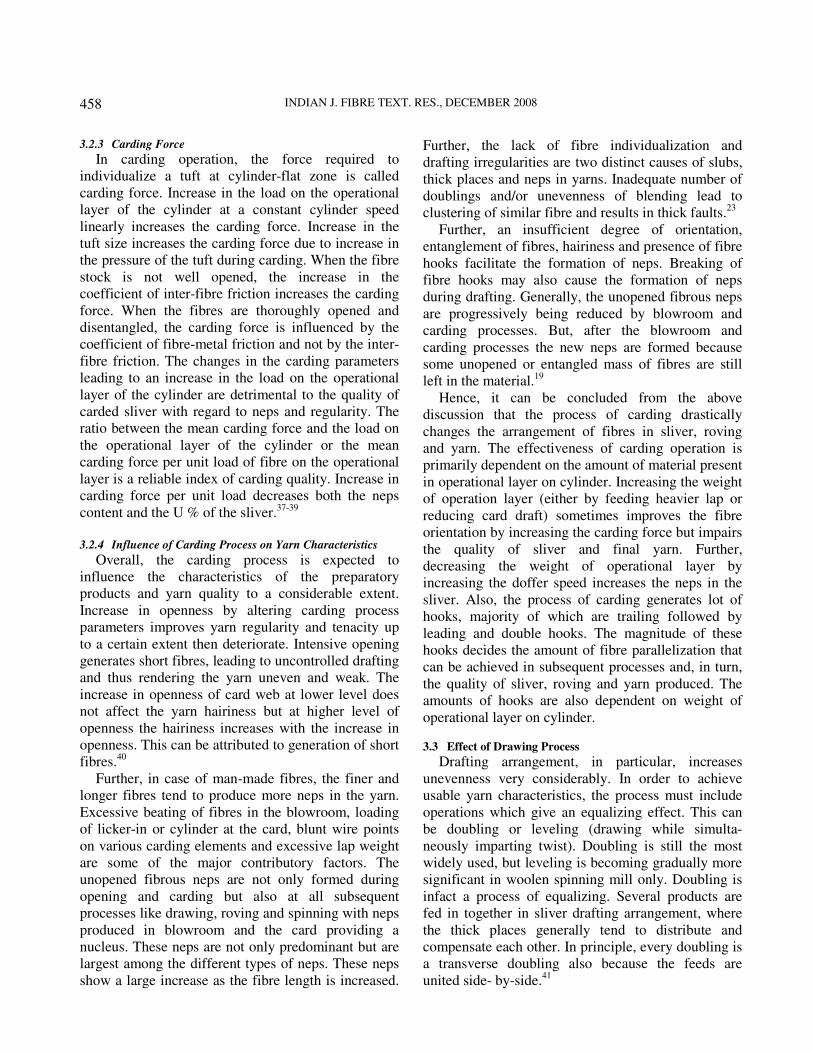
3.3.1 Influence of Drawframe on Fibre Straightening and
Hook Removal
It is well known that the drafting process, in
general, improves the fibre parallelization, and
straightens the hooks present in the card sliver. But
sometime due to excessive parallelization, fibres in
subsequent drawing process start relaxing. This can
be observed in Fig. 6. In the drafting arrangement the
fibre hooks may be embedded in the body of fibres
either as leading or as trailing hooks. A trailing hook
for a certain period moves with remainder of the fibre
strand at the speed of back roller towards the front
roller. If the fibre tip passes into the nip region of the
drawing roller, the fibre is accelerated. However,
since the trailing end is moving with a relatively thick
body of slowly moving fibres, the fibre is straightened
before the whole fibre can reach the drawing speed
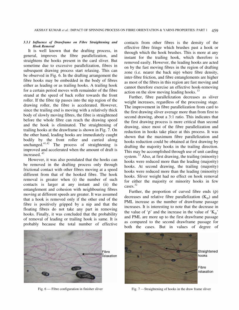
and the hook is eliminated. The straightening of
trailing hooks at the drawframe is shown in Fig. 7. On
the other hand, leading hooks are immediately caught
bodily by the front roller and carried along
unchanged.41,42
The process of straightening is
improved and accelerated when the amount of draft is
increased. 43
However, it was also postulated that the hooks can
be removed in the drafting process only through
frictional contact with other fibres moving at a speed
different from that of the hooked fibre. The hook
removal is greater when (i) the number of such
contacts is larger at any instant and (ii) the
entanglement and cohesion with neighbouring fibres
moving at different speeds are greater. It was assumed
that a hook is removed only if the other end of the
fibre is positively gripped by a nip and that the
floating fibres do not take any part in removing
hooks. Finally, it was concluded that the probability
of removal of leading or trailing hook is same. It is
probably because the total number of effective
contacts from other fibres is the density of the
effective fibre fringe which brushes past a hook or
through which the hook brushes. This is more at any
instant for the trailing hook, which therefore is
removed easily. However, the leading hooks are acted
on by the fast moving fibres in the region of drafting
zone (i.e. nearer the back nip) where fibre density,
inter-fibre friction, and fibre entanglements are higher
as most of the fibres in this region are fast moving and
cannot therefore exercise an effective hook-removing
action on the slow moving leading hooks. 13
Further, fibre parallelization decreases as sliver
weight increases, regardless of the processing stage.
The improvement in fibre parallelization from card to
the first drawing sliver average more than from first to
second drawing, about a 3:1 ratio. This indicates that
the first drawing process is more critical than second
drawing, since most of the fibre parallelization and
reduction in hooks take place at this process. It was
shown that the maximum fibre parallelization and
hooks reduction could be obtained at first drawing by
drafting the majority hooks in the trailing direction.
This may be accomplished through use of unit carding
system. 13
Also, at first drawing, the trailing (minority)
hooks were reduced more than the leading (majority)
hooks. At second drawing, the trailing (majority)
hooks were reduced more than the leading (minority)
hooks. Sliver weight had no effect on hook removal
for either the majority or minority hooks in few
cases.32
Further, the proportion of curved fibre ends (ρ)
decreases and relative fibre parallelization (Κrp) and
PML increase as the number of drawframe passage
increases. It is interesting to note that the decrease in
the value of ‘ρ’ and the increase in the value of ‘Κrp’
and PML are more up to the first drawframe passage
as compared to the second drawframe passage for
both the cases. But in values of degree of
Fig. 6 — Fibre configuration in finisher sliver
Fig. 7 —Straightening of hooks in the draw frame sliver
INDIAN J. FIBRE TEXT. RES., DECEMBER 2008
460
straightening of curved fibre ends (Eρ and Eκ), it is
observed that the value of ‘Eρ’ is more between the
first and the second drawframe passages. This may be
due to the feeding majority of trailing hooks as
trailing to the drafting system of second drawframe,
which straightens out the trailing hooks during
drafting.6,24
Further, with the constant carding conditions, the
ratio of majority hooks to minority hooks is constant
for a wide range of fibre mean length and a moderate
range of fibre fineness. During processing when
majority hooks trails in first and second drawing, the
increase in fibre parallelization over the conventional
drafting direction is independent of mean fibre
length.44
Furthermore, the fibres in the sliver exhibit
grouping behaviour during drafting. The grouping
behaviour is directly related to the drafting
performance with optimum roller setting leading to
lower grouping tendencies. Fibre orientation, fibre
type and the performance of earlier processes are
expected to be the major factors influencing the
grouping. This grouping behaviour is responsible for
the use of wider settings earlier in the process line. On
comparing for breaker and finisher drawings, there
appears to be longer fibre groups in the finisher
drawing. The longer group sizes are attributed to the
drafting process orienting the fibre groups along the
axis of the strand. Effects of fibre hooks and their
opening in the finisher drawing also play a part in the
longer group lengths observed.45
Significant improvements in the regularity of the
roving and the yarn result from the incorporation of
two additional drawings. The extent of improvement
varies with the type of material processed. It is
interesting to note that the improvements in the
evenness are not reflected in the strength of the yarn,
which is nearly unaffected by the use of additional
drawing. This is contrary to the earlier findings on
direct sliver-to-yarn spinning frame where improved
parallelization leads to better yarn strength. The results
have clearly demonstrated that the improved paralleli-
zation in the ingoing (feed) material contributes to
better drafting at both speed and ring frames. The use
of additional drawings thus offers a convenient means
of upgrading the evenness of carded cotton and man-
made staple fibre yarns. When additional drawings are
used with short staple material, it may be necessary to
maintain the sliver hank on coarser side in order to
minimize the incidence of stretch and sliver breaks at
the creel of the speed frame. 43
Further, the rotor yarn strength increases with the
increase in drawframe passages. This is mainly due to
better orientation of fibre and improvement in mean
fibre length at rotor groove with the increase in
drawframe passages, which is due to better fibre
extent in the yarn. Yarn uniformity could be improved
with the increase in number of drawframe passages.
Neps and thin places do not show any trend, but thick
places increase with the introduction of drawframe
passages. 46
3.3.2 Influence of Draft and Doublings
Apart from number of drawframes used, the
amount of draft and doublings at drawframe also
plays a crucial role in deciding the quality of sliver,
roving and yarn. Increase in draft and doublings
improve fibre parallelization, but decrease sliver
uniformity. The increase in fibre parallelization over
shadowed the decrease in sliver uniformity, resulting
in a decrease in spinning end breakage. Total draft
and doublings had no measurable effect on percentage
of hook reduction. There was a slight increase in fibre
parallelization and decrease in sliver uniformity with
increased draft and doublings, indicating that the fibre
parallelization and sliver uniformity were not directly
related. 32
Furthermore, the sliver irregularity can be evened
by doubling slivers together at the drawframe;
however, this evening action becomes ineffective as
the wavelength of the irregularity increases. 47
An 8-
fold doubling in comparison to the 6-fold doubling
does not cause any improvement on drafted sliver and
roving unevenness % and no significant difference in
the number of hooks in sliver. However, the reduction
in number of hooks at roving is more in case of 8-
doubling sliver. The increase in number of doublings
at drawframe does not cause any improvement in
mass unevenness in the ring and rotor yarns. The
tensile strength clearly increases in ring yarn with the
increase in number of drawframe passage because of
better parallelization of the fibres, and the related
increase in fibre-fibre friction. The increase in
doublings also increases the tensile strength. In rotor-
spun yarn, the tensile strength of the yarn produced
directly from the card sliver is even higher than that
of the yarn produced from drafted sliver. This proves
that the parallelization of the fibres deteriorates in
rotor spinning. The increase in number of doublings
decreases the breaking elongation in ring yarn but the
values are unaffected in the rotor yarn. An 8-fold
doubling on the drawing frame leads, for both yarn
AKSHAY KUMAR et al.: IMPACT OF SPINNING PROCESS ON FIBRE ORIENTATION & YARNS PROPERTIES: PART 1
461
types, no detectable reduction in number of thick
places.48
However, the increased number of doublings
not only improves the irregularity but also the mixing
in the sliver. The best strength was achieved with a
draft of eight and eight doublings, which gave only
slight changes in yarn evenness and imperfections.31
It
was also found that on drawing frame, the best overall
results are obtained by using light weight slivers and a
draft of eight and eight doublings.49
In general, it can be said from the above discussion
that the increase in number of draw frame passages or
number of doublings improves the properties of yarn.
Apart from the above two factors there are other
drawing parameters, which decide the fibre orient-
tation in sliver and hence affect the quality of yarn.
These factors are discussed briefly in subsequent
sections.
3.3.3 Influence of Direction of Hooks in Sliver
In general, feeding majority hooks in the leading
direction contributed to more irregularities and the
size of the effect was not dependent upon the draft or
the count spun. Direction of feed of the hooks had no
significant effect on irregularities at the can-fed speed
frame under normal conditions.
Feeding the leading hooks contributes to more yarn
irregularity and poorer strength, but the magnitude of
the effect was nearly of the same order, with the
second and third passage slivers as regards
irregularity and slightly more marked with second
passage sliver as regards strength. Apart from
improving the fibre parallelization, the use of
additional drawing also introduces a reversal in the
direction of drafting of the hooked ends at the
subsequent stage, and to evaluate the effect of
parallelization alone, the spinning with the same feed
directions must be compared. When this is done,
parallelization found to contribute towards better
drafting, as indicated by lesser number of
irregularities and higher strengths and the
improvement obtained seems to be of the same order
for both the feed directions of the majority hooks at
the ring frame. Favourable feed direction (obtained by
reversal) has, in general, greater effects on drafting
quality than parallelization (achieved through
additional drawing). The difference in drafting
irregularities due to fibre disorder and feed direction
does not vary much with the draft. Further, the draft
ratio has no effect on irregularity, a lower draft at the
front zone leads to slightly better yarn strength for all
input slivers. The relation between relative variance
and count shows that the effect of fibre arrangements
in the input sliver on drafting irregularities is not
sensitive to the count spun.43
Two passages of drawing followed by can-fed
speed frame are a standard processing sequence for
carded counts in a modern spinning layout. This is
because of the favourable drafting direction at the ring
frame and the minimum processing costs associated
with this system.43
In general, the trailing hook must
be presented to the ring spinning machine. Thus, there
should be an odd number of passages between the
card and the ring spinning machine.41
3.3.4 Influence of Drafting Force
The resistance met by the drafting roller when
drawing a sliver is called the drafting force.50
Basically, drafting takes place in three operating
stages, namely straightening of the fibre, elongation
of the fibres and sliding of the fibres out of the
surrounding fibre strand. So, the force acting on the
fibre called drafting force, which enables to move the
fibre by pulling it from the restraining force due to
relatively slow moving fibres in the back roller grip,
first increases sharply. This causes straightening and
extending of the fibres. Once the fibres start sliding,
drafting force drops down drastically. Overall drafting
force decreases as the draft increases, since a higher
degree of draft implies fewer fibres in the cross-
section. Besides this, drafting force is also dependent
on the arrangement of the fibre in the strand (parallel
or crossed), cohesion between the fibres (surface
structure, crimp and finish), fibre length and nip
spacing.41
Further, for a constant weight of sliver entering the
drafting zone, the drafting force in one zone is
inversely proportional to the draft and thus directly
proportional to the number of fibres being withdrawn
by the front rollers of the zone. When this number is
changed by feeding a heavier sliver, the force
increases more than in proportion to the weight. This
is because heavier slivers are more compact. But,
considering the forces in the different zones of
drawframe, it is proportional to the number of fibres
under the front rollers of a zone.51
However, for very
low drafts, the drafting force increases first to a peak
as the draft increases and then decreases.52
Furthermore, particularly for short fibres, a high ratio
of the number of fibres in front roller nip to the
number of fibres being delivered by the back roller at
any instant will cause an increase in pulling force
exerted by the faster fibres. But for apron drafting
INDIAN J. FIBRE TEXT. RES., DECEMBER 2008
462
systems, this ratio can be kept low enough to prevent
the bunching of the fibres dragged into the front roller
nip.53
However, there is no relationship between the
inter-fibre friction as a measure of drafting force and
drafting irregularity. This is because the overall
change in the inter-fibre friction would not affect the
motion of the floating fibre; to do this it would be
necessary to increase considerably the difference
between static and kinetic frictions.54
3.3.5 Drafting Wave
During the roller drafting of cotton, the rollers
cannot set much closer than the length of the longest
fibre and consequently most of the fibres are, for a
time, out of the control of the rollers. These fibres are
called floating fibres. The undue movement of these
floating fibres is responsible for the generation of a
periodic irregularity called drafting wave in the
material.55
The drafting wave is basically caused by the
position of the change point depending on the number
of fibres held by the front rollers. The thickness of
drafted sliver then tends to vary periodically. The
drafting waves in different length-wise strips of the
sliver are formed more or less independently. Further,
according to theory of drafting wave all the floating
fibres in the part of the drafting zone just behind the
front rollers are dragged rapidly forward by the fibres
held by front rollers, so that a gap free of floating
fibres is left in the sub-sliver. The fibres that are held
by the back rollers and then move forward with back
roller speed until the gap has passed into the drafted
sliver. The snatching process is then repeated and
caused a periodic irregularity, called drafting wave in
the material.56-59
However, in apron drafting, it is
considered that the irregularity due to the drafting
wave is at a low level because of the control affected
by the apron. However, the drafting wave is mainly
caused by the varying acceleration of floating fibres.57
Further, when high drafts are used without the
employment of a special drafting system the resulting
yarn is usually more irregular due to increase of
drafting wave amplitude.55
Overall, relative variance
of the sliver or roving also increases steadily as the
draft is increased. Further, there are two reasons why
the straightness and parallelism of the fibres affect the
amplitude of the drafting wave. In the first place, the
greater entanglement, which occurs when the fibres
are not parallel, prevents the smooth sliding of the
fibres past one another and so increases the tendency
of the fibres to go forward in clumps. Secondly, in
drafting, the fibres move in subgroup and the
independent drafting of the length-wise strips of the
sliver is more marked when the fibres are more nearly
parallel. The number of sub-slivers is therefore
greater, and the coefficient of variation of the drafting
wave is less. For the same cotton the irregularity of
the yarn is greater with the higher count; for the same
count the irregularity is less when the fibres are
finer.56
Overall increase in amplitude of drafting wave
impairs the quality of sliver and thus yarns.59
3.3.6 Sliver Strength
The force required to slide past the fibres in a sliver
is termed as sliver strength. The sliver strength can
also be used as a measure of fibre alignment in top-
making. The fibre alignment and sliver strength
increase during the first and second gillings, but only
a small increase during the third gilling. The principal
factors determining sliver strength are: (i) fibre length
and its variability, (ii) intrinsic fibre strength, (iii)
fibre-alignment, (iv) fibre-straightness and (v) sliver
tension during testing. But in gilling, the major
changes are those of fibre alignment along the axis of
the sliver and a reduction of fibre hooks.60
However, in cotton sliver, the fibre configuration
mainly affects the sliver strength. As the fibre
parallelization improves with the successive passages
of drawing, the sliver strength drops. In the card
sliver, the inter-fibre friction and sliver strength show
a positive correlation. But, as the fibre parallelization
improves with the successive passages of drawing, the
sliver strength drops and the difference in the strength
of the sliver having different frictional values
narrows. Thus, fibre orientation affects sliver strength
much more than the values of inter-fibre friction. 61
Further, the cotton slivers possess very lower
strength and are liable to unexpected drafting and
breakages during processing. If the sliver strength is
not appropriately controlled, sliver and roving become
uneven and frequent end breaks may occur. The
carded sliver tenacity is halved after the two drawing
passages. This is attributed to fibre-straightening and
fibre parallelization activity in the card slivers.
Further, the fibres became more straightened and
parallelized, and more intimately packed in the sliver,
leading to higher sliver density or lower sliver bulk.
This means that the sliver bulkiness reflects the fibre
straightening and fibre parallelization in the sliver.
Increase in number of drawing process leads to
decrease in sliver bulk and further reduction in sliver
AKSHAY KUMAR et al.: IMPACT OF SPINNING PROCESS ON FIBRE ORIENTATION & YARNS PROPERTIES: PART 1
463
strength along with an increase in fibre straightening
and fibre parallelization. The number of drawing
passages has more influence on the sliver strength
than the total draft and doublings experienced by the
slivers. This was probably due to the reversal of the
sliver processing direction at each drawing passage
that played an important role in the straightening and
parallelization of the fibres. Increase in draft/
doublings at the I drawframe passage increases the
strength of the sliver. This effect is diminished at the
II drawframe passage. The increase in number of
doublings at constant drawframe draft increases the
tenacity and evenness. The increase in tenacity is due
to reduced improvement in terms of fibre
straightening and fibre parallelization. It can be
deduced from the above discussion that the sliver
strength is affected by drafting conditions and fibre
orientation in sliver.62
Further, in viscose fibre, the
tenacity of I drawframe sliver is higher than card
sliver, whereas II drawframe sliver is having the
lowest value of tenacity.6 The increase in value of
‘Krpm’ increases the tenacity of carding and I stage of
drawframe sliver, whereas trend reverses in finisher
sliver due to fibre relaxation as shown in Fig. 7.
Overall, the literature on drawing process reveals
that the process of drafting adds to irregularity by
generation of drafting wave in the drafted material.
However, the number of doublings given on
drawframe reduces the amplitude of irregularity by
equalizing effect. Further, fibre straightness and
parallelization improve with the amount of draft but
deteriorate with the increase in number of doublings
given at draw frame. The fibre parallelization and
straightness and added irregularity in the sliver are
also dependent on feed direction of the sliver to the
drawframe. Thus, the properties of sliver are governed
by counteracting effect of drafting and doublings,
which, in turn, affects the quality of final yarn.
3.4 Effect of Roving Process
It is well known that the drafting of cotton sliver
and roving is accompanied by the increase in
irregularity. Though in the drawframe this increase is
not apparent as it is compensated by doubling, in the
speed and spinning frames the irregularity increases at
each machine until the yarn is many times more
irregular than the sliver from which it was made.
Further, the relation between the variance and the
draft is linear and the slope of the line increases
sharply as the hank feed is finer.56
However, for the best results from apron drafting,
adequate parallelization of fibres must be obtained in
the ingoing (feed) sliver. This is the reason why
concepts of apron drafting failed in the case of
drawframe. The fibres become more parallel and
straighten in comparison to the drawframe sliver and
do not get much chance to relax after drafting system
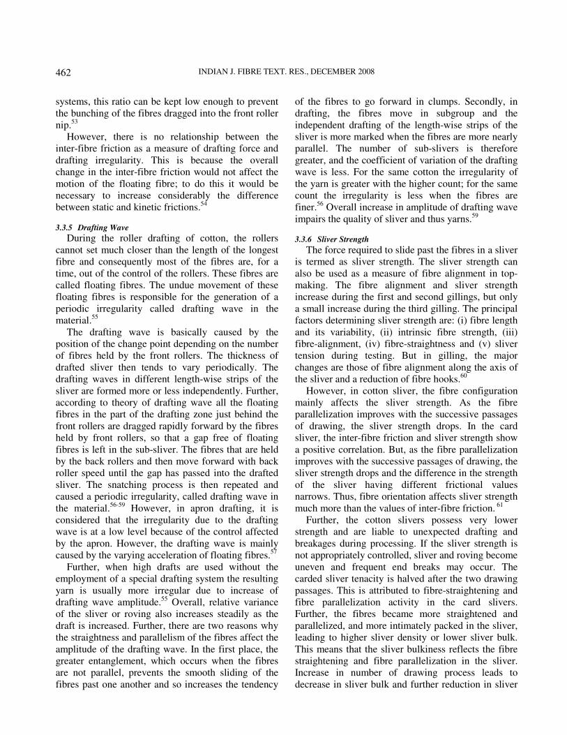
due to the presence of twist.6 The state of fibres in the
drafted roving is shown in Fig. 8. Further, in general
the irregularities added at the speed frame are not
influenced by the feed direction of the hooks in the
feed sliver especially for coarse roving. But it
acquires significant importance as the roving is made
finer. Feeding the hooks as leading results in more
irregularities in the case of finer roving.43
Furthermore, the products drafted on apron drafting
systems also exhibit drafting waves like roller
drafting. This suggests that the drafting wave is a
feature of drafting process and could originate from
factors other than uncontrolled acceleration of short
fibres. With cut staple fibre in particular the drafting
wave could result from acceleration of leading hooked
portion of the fibre which results in too early a feed
for some of the fibres or from elastic movement of
fibre assembly in the drafting zone. Finally, it appears
that the drafting waves introduced at the speed frame
are of low amplitude compared to other irregularities,
and reversal and drafting at the ring frame reduce the
amplitude further so that they are not seen in the yarn.
Further, the yarn produced from the roller drafting is
more irregular and weaker than that from apron
drafting, the difference in uniformity is more
pronounced than that in strength.63
3.4.1 Effect of Speed Frame Draft
Draft given at the speed frame is a crucial factor
affecting quality of roving and yarn. The increase in
the irregularity of a fibrous product during drafting is
the result of irregular fibre movements arising from
the following principal factors: (i) the irregularity of
Fig. 8 —Fibre configuration in roving
INDIAN J. FIBRE TEXT. RES., DECEMBER 2008
464
the product entering the drafting system, (ii) an
unsatisfactory technical condition of elements of the
drafting system, (iii) faults in its design and (iv)
structural unevenness i.e. uneven distribution of fibres
of different lengths in cross-section of the product.
The irregular movement increases with the draft and
with the difference in the lengths of the fibres in the
roving. It follows that the irregular movements occur
at any draft and in any drafting field and that their
magnitude increases with the draft.64
However, on speed frame drafting, the irregularity
added is relatively low and nearly independent of
draft.63
Contrary to the above, greater the draft at
speed frame, the higher will be the level of
parallelism in the roving.6,65
The higher roving draft
required for the heavy sliver influences parallelization
more effectively than roving evenness.49
In turn, the
increase in draft at speed frame improves the
properties of relatively poor carded material in ring
and rotor yarns.6
Apart from the amount of draft given at speed
frame, there are some other factors, which decide the
quality of roving produced. These factors are
described in forthcoming sections.
3.4.2 Drafting Force
In a double apron drafting system, the drafting
force increased with the size of the front beard, i.e.
with total draft, fibre length and speed of drafting.
The drafting force is decreased as break draft and
apron-to-apron spacing increased. There was a
difference in the force when the roving was fed in the
normal direction and then in the reverse, thus showing
that the effect of fibre hooking originated at the card
still persists at the spinning frame. For good spin, a
certain amount of fibre tension is necessary at the
front draft zone. But an excessive tension of the front
beard will not always lead to optimum conditions.
Further by measuring the drafting force at the front
draft zone, it was possible to detect the effect of fibre
hooking originated at the card. The force was higher
when the majority of hooks were trailing. Further a
certain amount of fibre tension is necessary in apron
zone for optimum yarn properties. Generally, high
values of drafting force are associated with the best
properties of the spun yarn, but too high a fibre
tension may lead to deterioration in yarn properties.66
3.4.3 Behaviour of Hooks in Roving Process
The relationship between the total amount of hooks
in sliver and roving for cotton is linear. Therefore, it
is sufficient to analyze hooks in sliver prior to roving
as a basis for evaluating the effects on yarn properties
and spinning end breakage. While converting sliver
into roving, the draft (approximately 8) should reduce
the amount of hooks. However, while measuring
hooks by the Lindsley technique, the twist in the
roving is not removed, and this hides or masks the
true reduction in the amount of hooks caused by the
roving draft.44
3.4.4 Roving Strength
Apart from the parameters, which decide sliver
strength, the roving strength is additionally dependent
on the amount of twist inserted in the roving. The
inter-dependence of twist and strength in roving may
be explained by two effects. Either the fibres slip or
they hold until the tension becomes too high and then
break. The amount of twist determines which of these
effects will occur. For small twist, parting is by fibre
slippage at a low tension. As the twist increases, the
strength also increases, but parting is still by slippage
up to the point where the strength is equal to the
combined breaking strength of all the fibres in the
cross-section. This is the maximum strength; further
increase in twist beyond this value means that the
parting is by fibre breakage, but the strength does not
increase and ultimately diminishes because of the
increased angle at which fibres are inclined to the
axis.67
Further, stronger finisher sliver produces
stronger roving.6
3.4.5 Effect of Roving Twist and Ring Frame Break Draft
The main objective of break draft is to straighten
and redistribute the roving twist to a greater length
before the main draft. Further, the higher twist in the
roving may exert some control over the short fibres
and so reduces the amplitude of the drafting wave.68
Also, on evaluation of the irregularity of drafting
roving by its performance on the ring frame, it was
revealed that as the break draft is too low, the twisted
roving cannot be properly drafted, resulting in
increase in thick places in yarn. But as the draft ratio
increases the drafting force increases and the fibre
crimps and hooks are straightened, which is beneficial
to improve uniformity of the drafted roving. Later,
fibres slip partially but the static friction has not yet
been overcome. In this zone, the drafting force
reaches a maximum value with increasing
fluctuations, which results in unsteady draft behaviour
and thus worsens the uniformity of the drafted roving.
When passing over the peak region, the fibres begin
to slip before the roving is completely drafted. In this
AKSHAY KUMAR et al.: IMPACT OF SPINNING PROCESS ON FIBRE ORIENTATION & YARNS PROPERTIES: PART 1
465
dynamic friction behaviour, both the force and its
fluctuation decrease. But it frequently causes a
drafting wave in the drafted roving because of the
higher draft ratio. This drafting wave remains in the
yarn and tends to cause serious thick and thin places
in the spun yarn. Higher break draft ratios increase the
U % of drafted roving and lower the yarn quality.69
Further, the migration of the fibres in the cross-
section of the roving impairs the mixing uniformity
achieved in the proceeding operations of the spinning
section. This migration generally increases with the
increase in twist in the roving.70
Also, as the break draft increases there is an
increase in the drafting tenacity (force required to
slide past the fibres in dynamic condition) up to a
maximum. This is followed by a decrease in the
tenacity for further increase in break draft. This is
because at lower break draft in the neighborhood of 1,
the fibre density in the cross-section of roving, i.e. the
fibre-to-fibre contact has not reached its maximum
value. But as the break draft increases so does fibre
density at back roller, until a maximum is reached,
after which fibre slippage begins. On reaching this
point, further increase in break draft entails a decrease
in fibre contact and drafting tenacity starts to decay.71
Furthermore, tenacity increases with the increase in
roving twist multiplier. However, this characteristic of
roving does not always lead to the expected increase
in yarn strength.72
Infact, the yarn tenacity increases
to a maximum value then decreases as the roving
twist multiplier (TM) increases. However, the yarn
uniformity first increases and then decreases with the
increase in roving TM in majority of the cases. This is
because the increase in roving TM increases the inter-
fibre friction due to more contact area, which creates
problem during drafting and ultimately deteriorates
the yarn quality. The imperfections in yarn do not
show any regular trend.29
For a given yarn count the
yarn property is superior with the medium hank
(about 2s Ne hank roving). Hence, the optimum draft
distribution is observed which exists between speed
and spinning frames from the point of view of
regularity and strength.63
Overall, the process of drafting at roving frame
adds irregularity in roving but the amplitude of
drafting wave is contained to an extent by apron
drafting. Further, an increase in draft at speed frame
improves yarn properties by reducing the draft
required at the ring frame. High strength roving,
produced with higher twist, produces higher tenacity
yarn due to less spreading of fibres in the drafting
zone. However, higher drafting force is required to
draft the high strength roving which may add to the
irregularity in the yarn. The increase in draft at the
speed frame increases fibre parallelization and
reduces number of hooks due to increased drafting
force acting on the fibre.
Thus, draft given at every stage of spinning
preparatory plays an important role in deciding
quality of the product produced on subsequent
machines and ultimately the properties of the yarn.
4 Conclusions The method of measuring fibre orientation
parameters at various stages in the spinning was
started in 1950s and still persisting. The modifications
in various measuring techniques were done but
principally the concept was almost similar. The
orientation parameters have a very good correlation
with the properties of sliver, roving and yarns and are
useful in explaining the effect of spinning process
parameters on properties.
It has been revealed that the carding is the most
important process stage, which affects the properties
of sliver, roving and ring, rotor and air-jet yarns. The
effect of drawing and doublings at subsequent stages
also plays a significant role in deciding the quality of
intermediate products and yarn quality. Speed frame
is also crucial process which decides the final quality
of yarn. The negative effect of preceding spinning
machine can be overcome by proper selection of
parameters at the speed frame. Finally, the draft
distribution and roving twist affect the quality of yarn
and should be decided judicially by proper
optimization.
References 1 Morton W E & Summers R J, Fibre arrangement in card
sliver, J Text Inst, 40 (1949) 106.
2 Lindsley C H, Measurement of fibre orientation, Text Res J,
21(1951)39-46.
3 Leont’eva I S, Problem of fibre straightening during sliver
preparation, Tech Text Ind USSR, (2) (1964)57-63.
4 Iyer I K P, Parathasarthy M S & Sundram V, Study on
different methods of measuring fibre configuration, Resume
of Papers, Twenty First Joint Technological Conference of
ATIRA, BTRA, and SITRA (Bombay Textile Research
Association, Bombay, India), 1980, 12-15.
5 Morton W E & Yen K C, The arrangement of fibres in fibro
yarns, J Text Inst, 43(1952) T463-T472.
6 Kumar A, Effect of drafts at different stages of spinning
process on fibre orientation and yarn properties, Ph D thesis,
Indian Institute of Technology, New Delhi, India, 2004.
INDIAN J. FIBRE TEXT. RES., DECEMBER 2008
466
7 Hearle J W S & Gupta B S, Migration of fibres in yarns: Part
III-A study of migration in staple fiber rayon yarn, Text Res
J, 35 (1965)788.
8 Hearle J W S, Grosberg P & Backer S, Structural Mechanics
of Fibres, Yarns, and Fabrics (Wiley-Interscience of John
Wiley & Sons, New York), 1969, 88.
9 Simpson J & Patureau M A, A method and instrument for
measuring fiber hooks and parallelization, Text Res J,
40(1970)956-957.
10 Audivert R, The effect of fiber hooks on the digital
fibrograph readings from clamped beards, Text Res J,
41(1971)365-366.
11 Balasubramanian N, Supanekar S D & Nerurkar S K,
Estimation of differential fiber hooking by fibrograph, Text
Res J, 45 (1975)296-302.
12 Deluca L B, An evaluation of hooked fibres in cotton sliver
on a relative basis, Text Res J, 35(1965)858- 861.
13 Garde A R, Wakankar V A & Bhaduri S N, Fibre
configuration in sliver and rovings and its effect on yarn
quality, Text Res J, 31(1961)1026-1036.
14 Ishtiaque S M, Distribution of fibres in cross-section of rotor-
and ring- spun yarns and their strength, Indian J Text Res,
11(1986)215.
15 Punj S K, Debnath S & Chowdhury A, Fibre distribution in
air-jet and ring yarns, Indian J Fibre Text Res, 26 (2001)251-
254.
16 Punj S K, Debnath S & Chowdhury A, Radial packing
density of MJS yarns, Indian J Fibre Text Res, 23(1998)229-
232.
17 Ishtiaque S M, Selected problems of internal structure of
rotor-spun yarn, Ph.D thesis, University of Mechanical and
Textile Engineering, Liberec, Czechoslovakia, 1983.
18 Ishtiaque S M, Chaudhuri S & Das A, Influence of fibre
openness on processibility of cotton and yarn quality: Part I –
Effect of blow room parameters, Indian J Text Res,
28(2003)399-404.
19 Ishtiaque S M, Influence of man-made fibres on
configuration of neps, Asian Text J, November (1993)13-15.
20 Chattopadhyay R, Quality considerations in blowroom,
Advances in Technology of Yarn Production, edited by R
Chattopadhyay (NCUTE, IIT-Delhi, India), 2002, 9-16.
21 Bhaduri S N, Effect of openness of cotton on subsequent
processing, Resume of Papers First Technological
Conference of ATIRA, BTRA, and SITRA (Bombay Textile
Research Association, Bombay, India), 1959.
22 Klein W, A short staple spinning series, A Practical Guide to
Opening and Carding (The Textile Institute), 1987.
23 Salhotra K R, Spinning of Manmades and Blends on Cotton
Systems (Textile Association India), 1989.
24 Ishtiaque S M & Vijay A, Optimization of ring frame
parameters for coarser preparatory, Indian J Fibre Text Res,
19(1994)239-246.
25 Ishtiaque S M, Present blowroom practices: Scope of
improvement, Advances in Technology of Yarn Production,
edited by R Chattopadhyay (NCUTE, IIT-Delhi, India),
2002, 23-41.
26 Salhotra K R, Significance of modern developments in
blowroom, Advances in Technology of Yarn Production,
edited by R Chattopadhyay (NCUTE, IIT-Delhi, India),
2002, 50-57.
27 Sengupta A K & Chatopadhyay R, Change in configuration
of fibres during transfer from cylinder to doffer in a card,
Text Res J, 52(1982)178-181.
28 Simpson J & Fiori L A, Effect of mixing cottons differing in
micronaire reading and carding variables on cotton sliver
quality, yarn properties, and end breakage, Text Res J,
44(1974)327-331.
29 Basu A, Effect of carding on the imperfections of cotton
yarns, Asian Text J, April(2002)74-78.
30 Simpson J, Relation between minority hooks and neps in the
card web, Text Res J, 42(1972)590-591.
31 Sands J E, Little H W & Fiori L A, Yarn production and
properties, Text Prog, 3(1971)34.
32 Simpson J, Sands J E & Fiori L A, The effect of drawing
frame variables on fibre hooks and parallelization and
processing performance, Text Res J, 40(1970)42-47.
33 Wolfgang T, High production carding and the quality of
combed cotton yarns, Melliand Textilber, 65(1984)E211-
E215.
34 Nerurkar S K, Detailed analysis of carding quality and its
influence on processing and yarn properties, Indian J Text
Res, 4(1979)63-70.
35 Rakshit A K & Balasubramanian N, Influence of carding
conditions on rotor spinning performance and yarn quality,
Indian J Text Res, 10(1985)158-162.
36 Rakshit A K & Balasubramanian N, Nep generation with
polynosic fibres in relation to surface characteristics of fibre,
Indian J Text Res, 8(1983)95-100.
37 Sengupta A K, Vijayaraghavan N & Singh A, Studies on
carding force between cylinder and flats in a card: Part I –
Effect of machine variables on carding force, Indian J Text
Res, 8 (1983)59.
38 Sengupta A K, Vijayaraghavan N & Singh A, Studies on
carding force between cylinder and flats in a card: Part II –
Effect of fibre and process factors, Indian J Text Res,
8(1983)64.
39 Sengupta A K, Vijayaraghavan N & Singh A, Studies on
carding force between cylinder and flats in a card: Part III –
Carding parameters, sliver quality and carding force, Indian J
Text Res, 8 (1983)68.
40 Ishtiaque S M, Chaudhuri S & Das A, Influence of fibre
openness on processibility of cotton and yarn quality: Part II
–Effect of carding parameters, Indian J Text Res, 28 (2003)
405-410.
41 Klein W, A short staple spinning series, The Technology of
Short- Staple Spinning (The Textile Institute, UK), 1987.
42 Dzhokharidze G V, The straightening of fibre hooks on the
card, Tech Text Ind USSR, (4) (1966)43-48.
43 Balasubramanian N & Bhatnagar V K, The effect of
disorientation of hooks in the input sliver on drafting
irregularities and yarn quality, Text Res J, 41(1971)750-759.
44 Deluca L B, Simpson J & Fiori L A, An evaluation of fibre
parallelization and drafting tenacity of cotton silver, Text Res
J, 38(1968)817- 823.
45 Grover G & Lord P R, The measurement of sliver properties
on the draw frame, J Text Inst, 83(1992)560-572.
46 Ishtiaque S M & Saxena A, Effect of sliver preparation on
fibre disorder at rotor groove, Indian J Text Res, 16 (1991)
233-235.
47 Bowles A H & Davies I, The influence of drawing and
doubling processes on the evenness of spun yarns: Part IV-
AKSHAY KUMAR et al.: IMPACT OF SPINNING PROCESS ON FIBRE ORIENTATION & YARNS PROPERTIES: PART 1
467
Extremely long-term variations, Text Inst and Ind January
(1979) 38-40.
48 Iyer C & Mavely J, Influence of doubling number on
longitudinal and transverse scattering of the yarn, optimum
doubling number in modern 3-cylinder spinning processes,
Melliand Textilber (Eng Edition), 57(1976)279-287.
49 Sands J E & Fiori L A, Yarn production and properties, Text
Prog, 3(1971)35.
50 Anbinder S U, Fibre straightening in the drafting field, Tech
Text Ind USSR, (4)(1969)43-47.
51 Foster G A R, Roller slip and the irregularity of cotton and
rayon-staple drawframe slivers: Part II— The nature of roller
slip and the theory of draft distribution, J Text Inst,
44(1953)T570-T572.
52 El-Sharkawy A F, Audivert R & Castellar D D, The relation
between the drafting force, draft, and setting in the roller-
drafting of staple-fibre slivers, J Text Inst, 64(1973)325-327.
53 Sengupta A K & Kapoor I M, Yarn evenness, Text Prog, 14
(1985)19.
54 Cavaney B & Foster GAR, Some observations on the
drafting forces of cotton and rayon-staple slivers, J Text Inst,
45(1954)T390-T404.
55 Foster G A R, Fibre motion in roller drafting, J Text Inst, 42
(1951) T335-T374.
56 Cavaney B & Foster G A R, The irregularity of materials
drafted on cotton spinning machinery and its dependence on
draft, doubling and roller setting: Part I—The speed frames,
J Text Inst, 45(1954) T529-T549.
57 Fujino K, Shimotsuma Y & Fuji T, A study on apron-
drafting: Part I−Experimental studies, J Text Inst, 68 (1977)
131-140.
58 Slater K, Yarn evenness, Text Prog, 14 (1985) 17.
59 Bakhar M I, Yarn evenness. Text Prog, 14 (1985) 17.
60 Ross D A, Bratt R L & Story L F, Sliver strength as a
measure of fibre-alignment in topmaking, J Text Inst,
53(1962) 185.
61 Mehta I H & Nanal S Y, The effect of varying interfibre
friction on hook removal during drawing, Text Res J,
40(1970)1131-1132.
62 Miao M, Ning F & How Y, Cotton sliver strength and
withdrawal speed limit, J Text Inst, 89(1998)468-479.
63 Balasubramanian N, A study of the irregularities added in
apron drafting, Text Res J, 39(1969)155-165.
64 Nemzer G M, Reducing irregularity in sliver, roving and
yarn, Tech Text Ind USSR, (2)(1961)66-73.
65 Sippel A, The relationship between minimum twist of
cohesion and cutting ratio in cotton rovings, Text Res J,
35(1965)283-288.
66 Audivert R, Villaronga M & Coscolla R, Drafting force in
the front zone of a double apron drafting system, Text Res J,
37(1967)1-10.
67 Hannah M, The theory of high drafting, J Text Inst, 41
(1950) T57-T89.
68 Anderson S L & Foster G A R, The irregularity of materials
drafted on cotton spinning machinery and its dependence on
draft, doubling and roller setting: Part II−The spinning
frame, J Text Inst, 46(1955)T551-T564.
69 Su C I, Evaluating uniformity of drafted roving, Text Res J,
69(1999)630-634.
70 Tikhomirova A I, Investigation of transverse sections of
roving and yarn, Tech Text Ind USSR, (3)(1970)43-46.
71 Audivert R, ABC’s of drafting tenacity, Text Ind,
133(1969)125-189.
72 Barella A & Sust A, Cohesion phenomena in rovings and
yarns: Part IV- Cohesion of twisted rovings, its effect on
yarn properties, Text Res J, 35(1965)491-496.