Embed Size (px)
Citation preview

H.Kim et al., UCSD 1
Disclaimer for FAA Research Publication
Although the FAA has sponsored this project, it neither endorses nor rejects the
findings of the research. The presentation of this information is in the interest of
invoking technical community comment on the results and conclusions of the
research.
H.Kim et al., UCSD 2
Impact Damage Formation on Composite Aircraft Structures
Hyonny Kim, Gabriella DeFrancisci, Daniel Whisler, Jennifer Rhymer Department of Structural Engineering, University of California San Diego
La Jolla, CA 92093-0085
Project Description Paper Supporting Presentation Given at Federal Aviation Administration Joint Advanced Materials & Structures (JAMS)
5th Annual Technical Review Meeting 21-22 July 2009, NIAR/WSU, Wichita, KS
Abstract
The ongoing FAA research activities at UCSD, summarized herein, are
composed of: (i) large-scale blunt impact, (ii) lab-scale blunt impact, and (iii) hail
ice impact. The blunt impact studies are focused on understanding the
development of the formation of massive internal damage to composite fuselage,
when contact is made by ground vehicles/equipment, with little or no external
visible detectability. The hail ice impact work seeks to establish a database for
the formation of damage by high velocity ice impacts, and to establish models for
predicting damage initiation failure thresholds as well the final state of damage
produced.
H.Kim et al., UCSD 3
1.0 Introduction
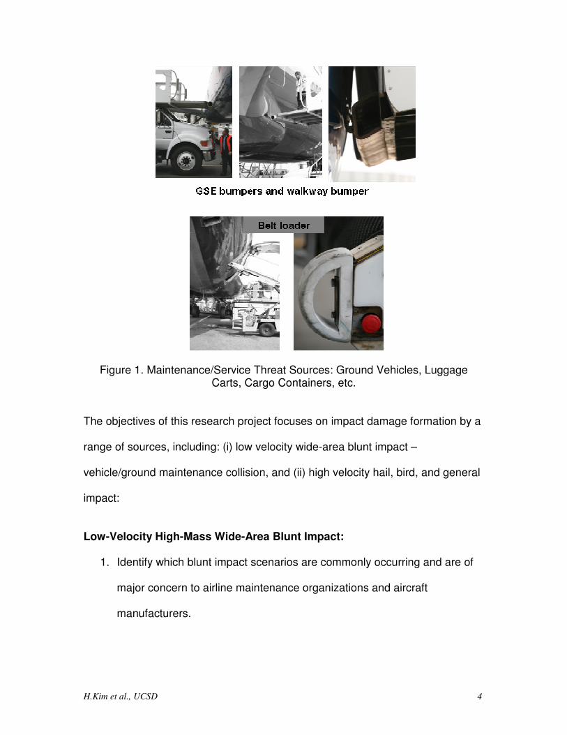
Impact damage resulting from collisions of ground vehicles/equipment with
aircraft structural components, as well as from events such as hail and bird
strikes, is a significant source of damage to commercial aircraft that has the
potential to go by undetected. Impacts by hail and birds can occur at in-flight
velocities, thereby posing significant threats to the structure. More commonly
occurring, however, are blunt impact threats such as ground maintenance and
service vehicles, equipment, etc., as shown in Figure 1. With new all-composite
fuselage transport aircraft coming into service, significantly more composite skin
surface area is exposed to such impacts. To address the difficulties that exist in
being able to predict and detect the damage resulting from blunt impact, and to
aid in assessing its effect on structural performance, focused investigation on the
development of impact damage is needed. Of particular interest is damage that
can be difficult to visually detect from the exterior, but could be extensive below
the skin’s outer surface. Sub-surface damage (typically delamination and
backside fiber failure) usually forms in a panel skin when impacts occur at levels
just exceeding the amount needed to initiate failure (Kim et al. [1], Kim and
Kedward [2]). This level is referred to as the failure threshold energy.
Additionally, damage from blunt impacts to internal stiffeners can be extensive,
as well as debonding between the stiffener and the skin. Of critical concern is
whether such extensive damage can result in the structure losing limit load
capability.
H.Kim et al., UCSD 4
Figure 1. Maintenance/Service Threat Sources: Ground Vehicles, Luggage Carts, Cargo Containers, etc.
The objectives of this research project focuses on impact damage formation by a
range of sources, including: (i) low velocity wide-area blunt impact –
vehicle/ground maintenance collision, and (ii) high velocity hail, bird, and general
impact:
Low-Velocity High-Mass Wide-Area Blunt Impact:
1. Identify which blunt impact scenarios are commonly occurring and are of
major concern to airline maintenance organizations and aircraft
manufacturers.
H.Kim et al., UCSD 5
2. Develop Methodology for Blunt Impact Threat Characterization and
Prediction.
3. Experimental identification of key phenomena and parameters governing
high energy blunt impact damage formation, particularly focusing on what
conditions relate to the development of massive damage occurring with
minimal or no visual detectability on the impact side.
4. Damage tolerance assessment of blunt impact damaged structures with
focus on conditions related to loss of limit load capability for level of
damage incurred, and which types of structural configurations and details
are more prone to this loss of capability.
High Velocity Hail, Bird, and General Impact:
1. Investigate impact damage initiation and damage formation to composite
panels, including those of skin-stiffened and sandwich construction.
2. Develop models capable of predicting impact damage to composite
panels.
3. Develop unified treatment methodology for predicting damage initiation by
variety of impactor projectile types – e.g., bird, hail, tire fragment, runway
debris, lost access panel, etc.
Accomplishment of these objectives are intended to aid maintenance engineers
in assessing whether an incident could have caused damage to a structure, and
if so, what sort of inspection technique should be applied to resolve the extent of
damage. Furthermore, it is expected that design engineers can make use of the
research outcomes to: (i) improve the resistance of composite aircraft structures
H.Kim et al., UCSD 6
to damage from blunt impacts as well as a variety of other sources such as hail-
and bird-strikes, runway debris, lost access panel, etc, and (ii) provide critical
information on the mode and extent of seeded damage, particularly those not
easily detected by visual inspection, resulting from a wide gamut of impact
threats – i.e., low to high velocity.
2.0 Project Results to Date
The results of the three project activities are described in separate subsections.
(i) large-scale blunt impact, (ii) lab-scale blunt impact, and (iii) hail ice impact.
2.1 Large-Scale Blunt Impact
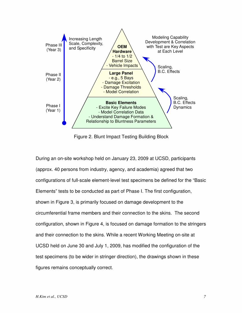
2.1.1 Test Specimens The large-scale blunt impact experimental activities planned at UCSD are to be
conducted over multiple years, as described by the “building block” pyramid
shown in Figure 2. The First year of activity will focus on establishing a basic
understanding of key failure modes, how these are excited in relationship to
bluntness parameters and incidence angle of the impact, and the establishment
of a “clean” database measuring structural response and failure development. In
addition to assessing the mechanisms of how blunt impact damage forms, these
data will be critical to the development of modeling methodology and simulation
tools for predicting damage.
H.Kim et al., UCSD 7
Basic Elements- Excite Key Failure Modes- Model Correlation Data
- Understand Damage Formation &Relationship to Bluntness Parameters
Large Panel- e.g., 5 Bays
- Damage Excitation- Damage Thresholds- Model Correlation
OEMHardware- 1/4 to 1/2Barrel Size
- Vehicle Impacts
Scaling,B.C. EffectsDynamics
Scaling,B.C. Effects
Increasing LengthScale, Complexity,and Specificity
Phase III(Year 3)
Phase II(Year 2)
Phase I(Year 1)
Modeling CapabilityDevelopment & Correlationwith Test are Key Aspects
at Each Level
Figure 2. Blunt Impact Testing Building Block
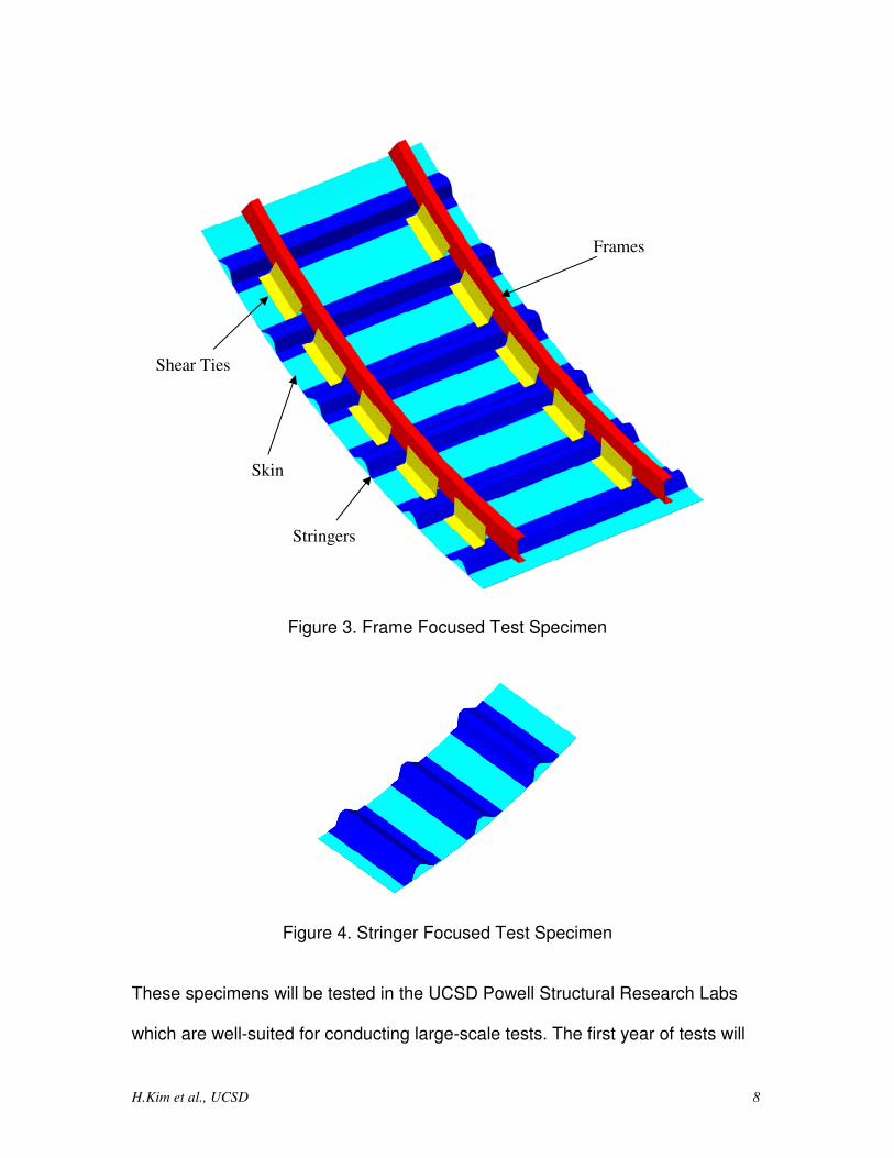
During an on-site workshop held on January 23, 2009 at UCSD, participants
(approx. 40 persons from industry, agency, and academia) agreed that two
configurations of full-scale element-level test specimens be defined for the “Basic
Elements” tests to be conducted as part of Phase I. The first configuration,
shown in Figure 3, is primarily focused on damage development to the
circumferential frame members and their connection to the skins. The second
configuration, shown in Figure 4, is focused on damage formation to the stringers
and their connection to the skins. While a recent Working Meeting on-site at
UCSD held on June 30 and July 1, 2009, has modified the configuration of the
test specimens (to be wider in stringer direction), the drawings shown in these
figures remains conceptually correct.
H.Kim et al., UCSD 8
Figure 3. Frame Focused Test Specimen
Figure 4. Stringer Focused Test Specimen
These specimens will be tested in the UCSD Powell Structural Research Labs
which are well-suited for conducting large-scale tests. The first year of tests will
Skin
Stringers
Frames
Shear Ties
H.Kim et al., UCSD 9
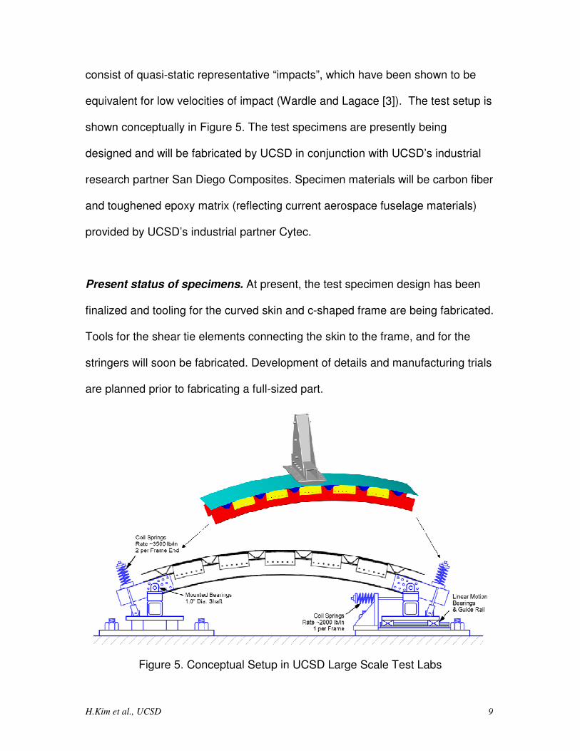
consist of quasi-static representative “impacts”, which have been shown to be
equivalent for low velocities of impact (Wardle and Lagace [3]). The test setup is
shown conceptually in Figure 5. The test specimens are presently being
designed and will be fabricated by UCSD in conjunction with UCSD’s industrial
research partner San Diego Composites. Specimen materials will be carbon fiber
and toughened epoxy matrix (reflecting current aerospace fuselage materials)
provided by UCSD’s industrial partner Cytec.
Present status of specimens. At present, the test specimen design has been
finalized and tooling for the curved skin and c-shaped frame are being fabricated.
Tools for the shear tie elements connecting the skin to the frame, and for the
stringers will soon be fabricated. Development of details and manufacturing trials
are planned prior to fabricating a full-sized part.
Figure 5. Conceptual Setup in UCSD Large Scale Test Labs
H.Kim et al., UCSD 10
2.1.2 Boundary Conditions. Boundary conditions are a critical aspect of this project. Of primary importance is
that the “small” sized test specimen to be tested at UCSD has the same stress
state and key deformation metrics as a full-sized barrel being impacted by the
same conditions. This can be achieved by specifying appropriate boundary
conditions on all four sides of the test specimen. A methodology, using FEA
models of full-sized barrels and of the test specimens, is shown in Figure 6. The
full-barrel model will be analyzed with blunt impact conditions applied, from which
key stress and deformation quantities are determined. In parallel, a modified full-
barrel model having a cutout zone representing the test specimen will be
interrogated with relevant edge loadings and moments. The rotational and
translational stiffness can be determined on all four sides in this manner. These
stiffnesses, referred to as ki in Figure 6, will be applied to the “small” panel
specimen model boundaries, and the stress and deformation quantities extracted
from this model will be compared with those corresponding values from the full-
barrel model. Iteration of ki is likely needed until these quantities match (within
acceptable tolerance). In this manner, the test specimen can be made to
represent the stress and deformation state of the full-barrel. These boundary
stiffnesses would be implemented by a set of high-stiffness coil springs as
illustrated in Figure 5.
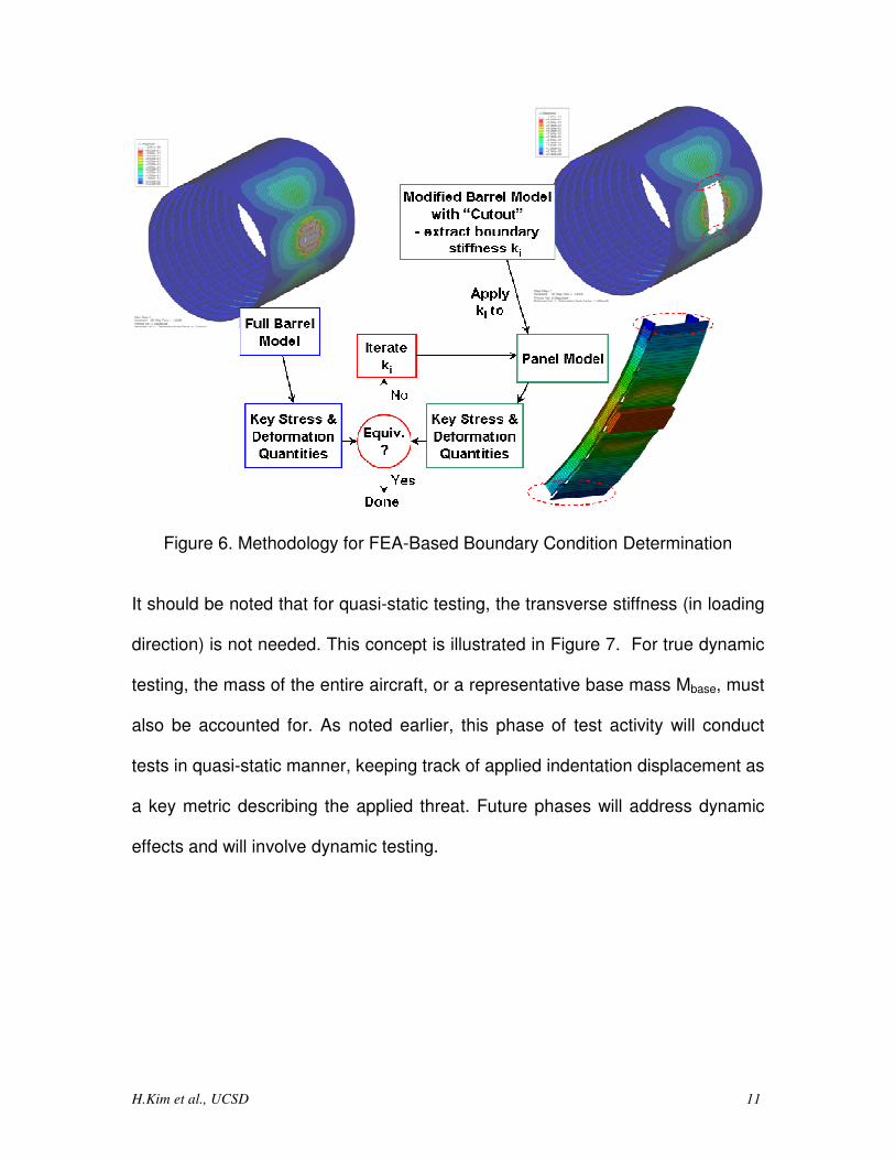
H.Kim et al., UCSD 11
Figure 6. Methodology for FEA-Based Boundary Condition Determination
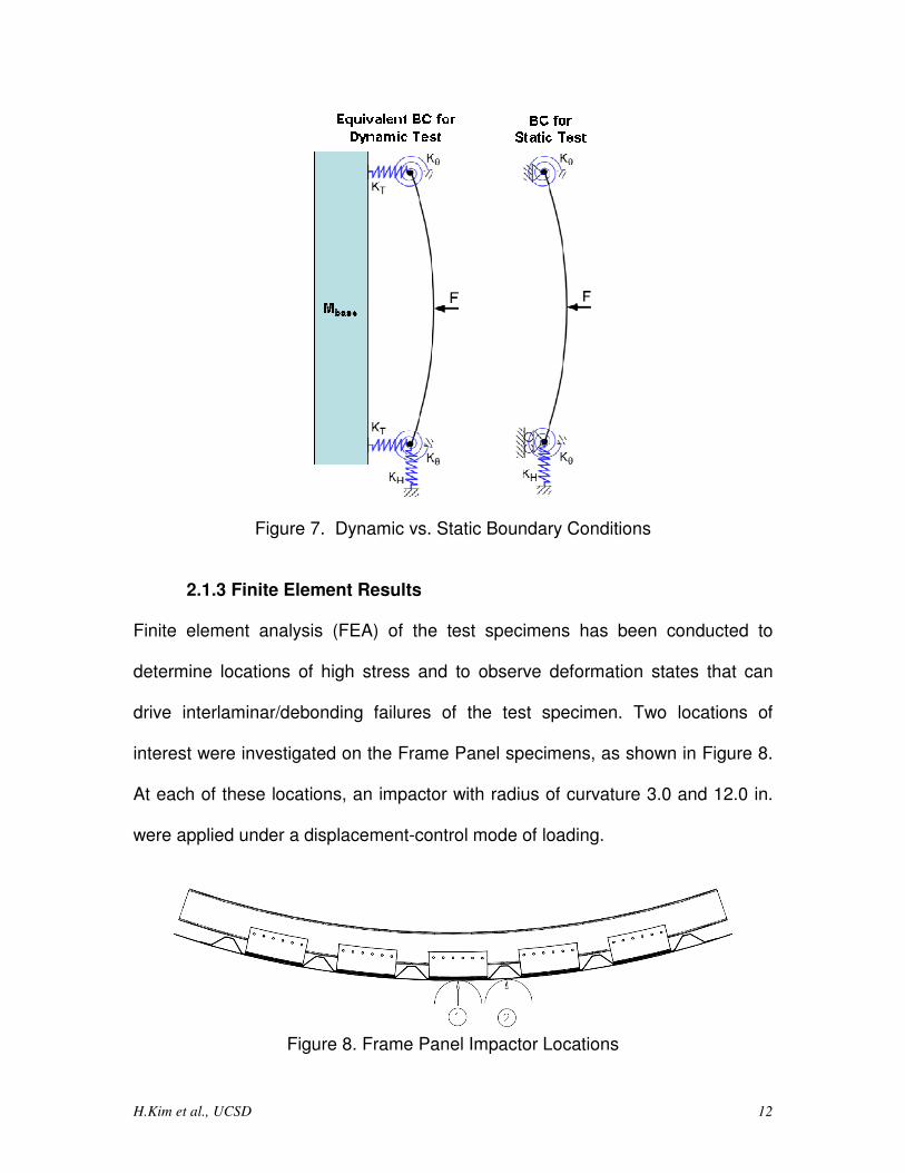
It should be noted that for quasi-static testing, the transverse stiffness (in loading
direction) is not needed. This concept is illustrated in Figure 7. For true dynamic
testing, the mass of the entire aircraft, or a representative base mass Mbase, must
also be accounted for. As noted earlier, this phase of test activity will conduct
tests in quasi-static manner, keeping track of applied indentation displacement as
a key metric describing the applied threat. Future phases will address dynamic
effects and will involve dynamic testing.
H.Kim et al., UCSD 12
Figure 7. Dynamic vs. Static Boundary Conditions
2.1.3 Finite Element Results
Finite element analysis (FEA) of the test specimens has been conducted to
determine locations of high stress and to observe deformation states that can
drive interlaminar/debonding failures of the test specimen. Two locations of
interest were investigated on the Frame Panel specimens, as shown in Figure 8.
At each of these locations, an impactor with radius of curvature 3.0 and 12.0 in.
were applied under a displacement-control mode of loading.
Figure 8. Frame Panel Impactor Locations
H.Kim et al., UCSD 13
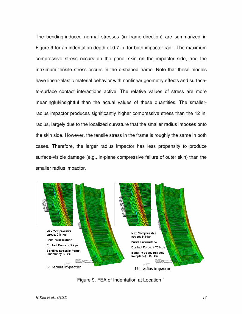
The bending-induced normal stresses (in frame-direction) are summarized in
Figure 9 for an indentation depth of 0.7 in. for both impactor radii. The maximum
compressive stress occurs on the panel skin on the impactor side, and the
maximum tensile stress occurs in the c-shaped frame. Note that these models
have linear-elastic material behavior with nonlinear geometry effects and surface-
to-surface contact interactions active. The relative values of stress are more
meaningful/insightful than the actual values of these quantities. The smaller-
radius impactor produces significantly higher compressive stress than the 12 in.
radius, largely due to the localized curvature that the smaller radius imposes onto
the skin side. However, the tensile stress in the frame is roughly the same in both
cases. Therefore, the larger radius impactor has less propensity to produce
surface-visible damage (e.g., in-plane compressive failure of outer skin) than the
smaller radius impactor.
Figure 9. FEA of Indentation at Location 1
H.Kim et al., UCSD 14
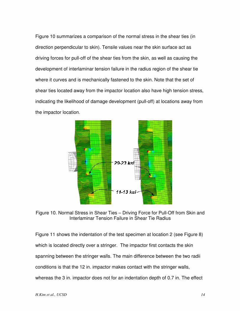
Figure 10 summarizes a comparison of the normal stress in the shear ties (in
direction perpendicular to skin). Tensile values near the skin surface act as
driving forces for pull-off of the shear ties from the skin, as well as causing the
development of interlaminar tension failure in the radius region of the shear tie
where it curves and is mechanically fastened to the skin. Note that the set of
shear ties located away from the impactor location also have high tension stress,
indicating the likelihood of damage development (pull-off) at locations away from
the impactor location.
Figure 10. Normal Stress in Shear Ties – Driving Force for Pull-Off from Skin and Interlaminar Tension Failure in Shear Tie Radius
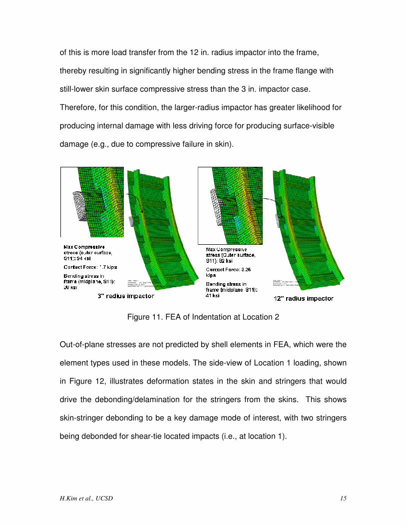
Figure 11 shows the indentation of the test specimen at location 2 (see Figure 8)
which is located directly over a stringer. The impactor first contacts the skin
spanning between the stringer walls. The main difference between the two radii
conditions is that the 12 in. impactor makes contact with the stringer walls,
whereas the 3 in. impactor does not for an indentation depth of 0.7 in. The effect
H.Kim et al., UCSD 15
of this is more load transfer from the 12 in. radius impactor into the frame,
thereby resulting in significantly higher bending stress in the frame flange with
still-lower skin surface compressive stress than the 3 in. impactor case.
Therefore, for this condition, the larger-radius impactor has greater likelihood for
producing internal damage with less driving force for producing surface-visible
damage (e.g., due to compressive failure in skin).
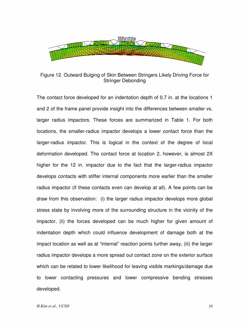
Figure 11. FEA of Indentation at Location 2 Out-of-plane stresses are not predicted by shell elements in FEA, which were the
element types used in these models. The side-view of Location 1 loading, shown
in Figure 12, illustrates deformation states in the skin and stringers that would
drive the debonding/delamination for the stringers from the skins. This shows
skin-stringer debonding to be a key damage mode of interest, with two stringers
being debonded for shear-tie located impacts (i.e., at location 1).
H.Kim et al., UCSD 16
Figure 12. Outward Bulging of Skin Between Stringers Likely Driving Force for Stringer Debonding
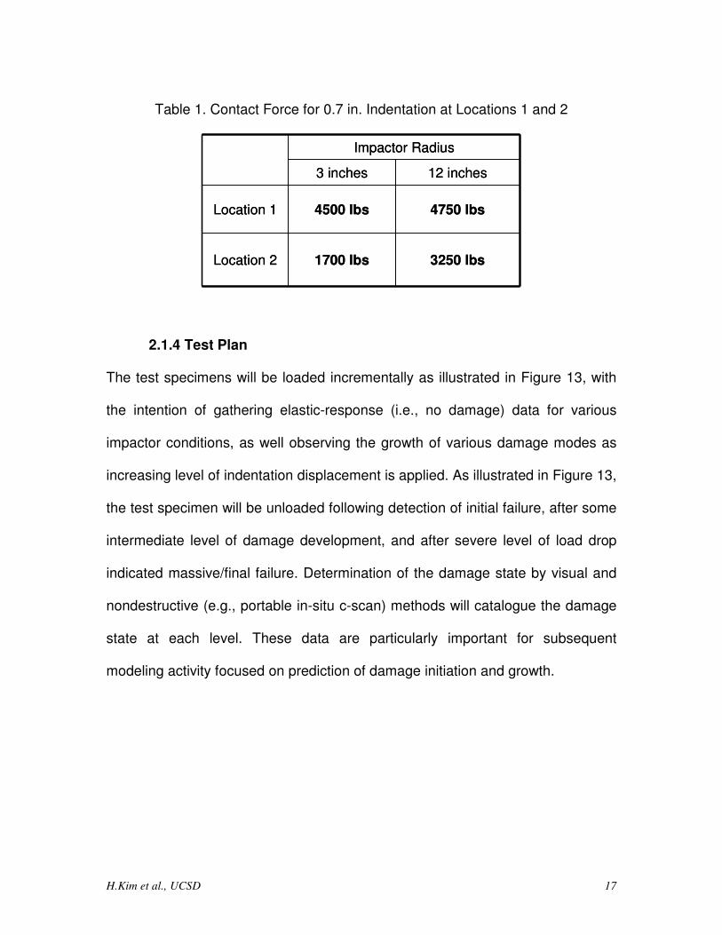
The contact force developed for an indentation depth of 0.7 in. at the locations 1
and 2 of the frame panel provide insight into the differences between smaller vs.
larger radius impactors. These forces are summarized in Table 1. For both
locations, the smaller-radius impactor develops a lower contact force than the
larger-radius impactor. This is logical in the context of the degree of local
deformation developed. The contact force at location 2, however, is almost 2X
higher for the 12 in. impactor due to the fact that the larger-radius impactor
develops contacts with stiffer internal components more earlier than the smaller
radius impactor (if these contacts even can develop at all). A few points can be
draw from this observation: (i) the larger radius impactor develops more global
stress state by involving more of the surrounding structure in the vicinity of the
impactor, (ii) the forces developed can be much higher for given amount of
indentation depth which could influence development of damage both at the
impact location as well as at “internal” reaction points further away, (iii) the larger
radius impactor develops a more spread out contact zone on the exterior surface
which can be related to lower likelihood for leaving visible markings/damage due
to lower contacting pressures and lower compressive bending stresses
developed.
H.Kim et al., UCSD 17
Table 1. Contact Force for 0.7 in. Indentation at Locations 1 and 2
3250 lbs1700 lbsLocation 2
4750 lbs4500 lbsLocation 1
12 inches3 inches
Impactor Radius
3250 lbs1700 lbsLocation 2
4750 lbs4500 lbsLocation 1
12 inches3 inches
Impactor Radius
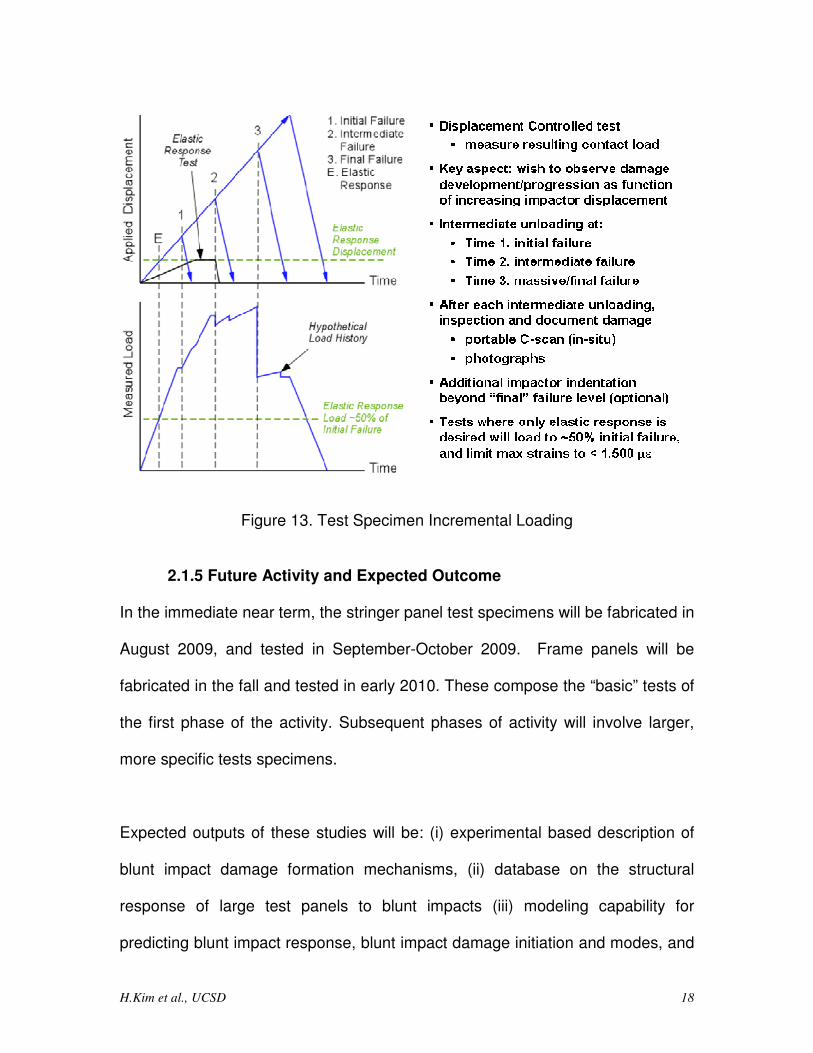
2.1.4 Test Plan The test specimens will be loaded incrementally as illustrated in Figure 13, with
the intention of gathering elastic-response (i.e., no damage) data for various
impactor conditions, as well observing the growth of various damage modes as
increasing level of indentation displacement is applied. As illustrated in Figure 13,
the test specimen will be unloaded following detection of initial failure, after some
intermediate level of damage development, and after severe level of load drop
indicated massive/final failure. Determination of the damage state by visual and
nondestructive (e.g., portable in-situ c-scan) methods will catalogue the damage
state at each level. These data are particularly important for subsequent
modeling activity focused on prediction of damage initiation and growth.
H.Kim et al., UCSD 18
Figure 13. Test Specimen Incremental Loading
2.1.5 Future Activity and Expected Outcome In the immediate near term, the stringer panel test specimens will be fabricated in
August 2009, and tested in September-October 2009. Frame panels will be
fabricated in the fall and tested in early 2010. These compose the “basic” tests of
the first phase of the activity. Subsequent phases of activity will involve larger,
more specific tests specimens.
Expected outputs of these studies will be: (i) experimental based description of
blunt impact damage formation mechanisms, (ii) database on the structural
response of large test panels to blunt impacts (iii) modeling capability for
predicting blunt impact response, blunt impact damage initiation and modes, and
H.Kim et al., UCSD 19
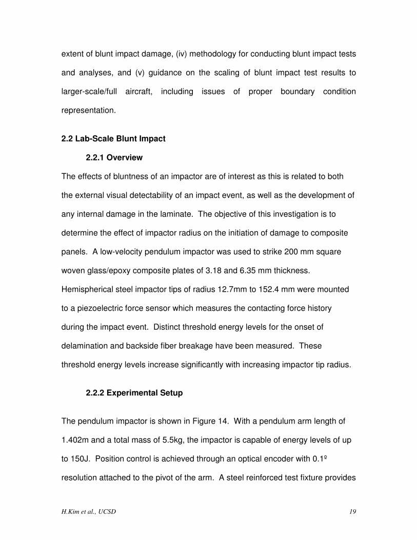
extent of blunt impact damage, (iv) methodology for conducting blunt impact tests
and analyses, and (v) guidance on the scaling of blunt impact test results to
larger-scale/full aircraft, including issues of proper boundary condition
representation.
2.2 Lab-Scale Blunt Impact
2.2.1 Overview The effects of bluntness of an impactor are of interest as this is related to both
the external visual detectability of an impact event, as well as the development of
any internal damage in the laminate. The objective of this investigation is to
determine the effect of impactor radius on the initiation of damage to composite
panels. A low-velocity pendulum impactor was used to strike 200 mm square
woven glass/epoxy composite plates of 3.18 and 6.35 mm thickness.
Hemispherical steel impactor tips of radius 12.7mm to 152.4 mm were mounted
to a piezoelectric force sensor which measures the contacting force history
during the impact event. Distinct threshold energy levels for the onset of
delamination and backside fiber breakage have been measured. These
threshold energy levels increase significantly with increasing impactor tip radius.
2.2.2 Experimental Setup
The pendulum impactor is shown in Figure 14. With a pendulum arm length of
1.402m and a total mass of 5.5kg, the impactor is capable of energy levels of up
to 150J. Position control is achieved through an optical encoder with 0.1º
resolution attached to the pivot of the arm. A steel reinforced test fixture provides
H.Kim et al., UCSD 20
the mount for two 12.7mm thick aluminum picture frame fixture with a 165 x 165
mm window (see Figure 14).
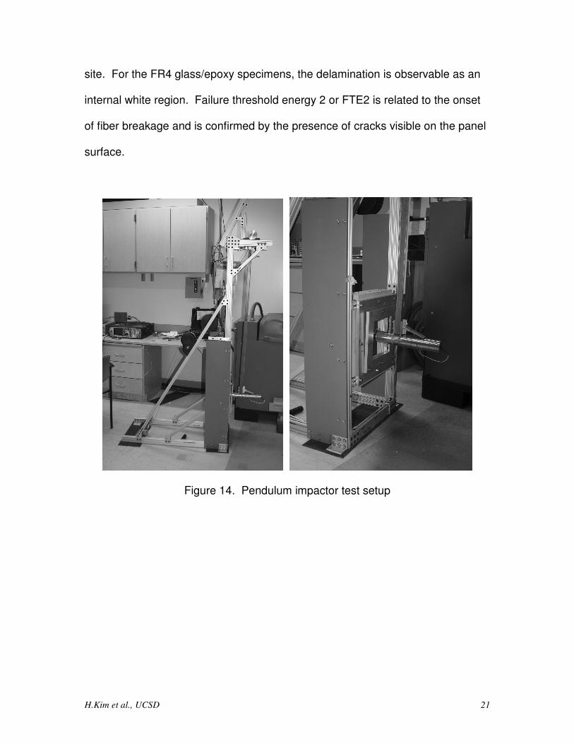
Force measurements are achieved via a piezo-electric sensor with a 0-5V range
output. Two different sensors are available: a 19mm diameter, 22.24kN max
force Dytran model 1050V6 sensor and a 50.8mm diameter, 111.2kN max force
Dytran model 1060V5. Both sensors accept custom-shaped tips. Three different
spherical tips (see Figure ) with radius 12.7mm, 50.8mm, and 152.4mm are used
in this study to investigate increasing levels of bluntness.
The material tested is FR4 woven fiberglass/epoxy. Panels are cut to
approximately 200 x 200 mm and are either 3.18mm or 6.35mm thick. The
material properties are E=18.6GPa, ν=0.18, and ρ=1860kg/m3.
2.2.3 Test Methodology The matrix provided in Error! Reference source not found. shows the six
different test scenarios available for three impactor tips and two panel
thicknesses. For each case, two different test protocols are used: "sweeping"
and "bracketing". Sweeping is a single panel tested at multiple increasing energy
levels until it fails. Bracketing tests a single panel at energy levels just below,
above, and right at failure. To be clear, failure is defined in this research project
based on two distinct mode of damage. Failure threshold energy 1 or FTE1 is
the projectile kinetic energy to just initiate delamination, localized to the impact
H.Kim et al., UCSD 21
site. For the FR4 glass/epoxy specimens, the delamination is observable as an
internal white region. Failure threshold energy 2 or FTE2 is related to the onset
of fiber breakage and is confirmed by the presence of cracks visible on the panel
surface.
Figure 14. Pendulum impactor test setup
H.Kim et al., UCSD 22
Figure 15. Impactor tips and force sensors; tip radius dimensions in mm
Table 2. Test Matrix
Number of Panels Tested for each Thickness T, Impactor Tip Radius R
R 12.7mm R 50.8mm R 152.4mm T 3.18mm 9 10 8 T 6.35mm 9 7 7
Each test run is conducted as follows. The fiberglass panel is clamped in place
and centered in the test fixture. Simple energy based calculations convert the
desired kinetic energy at impact to a specific angular position (i.e., potential
energy level of raised impactor mass). The pendulum arm is then raised
accordingly and a pneumatic locking mechanism secures it in place. Carbon and
R6.35 R12.7
R152.4 R101.6 R50.8 R25.4
Small Impact Tips
Large Impact Tips
Large Force Sensor
Small Force
Sensor
H.Kim et al., UCSD 23
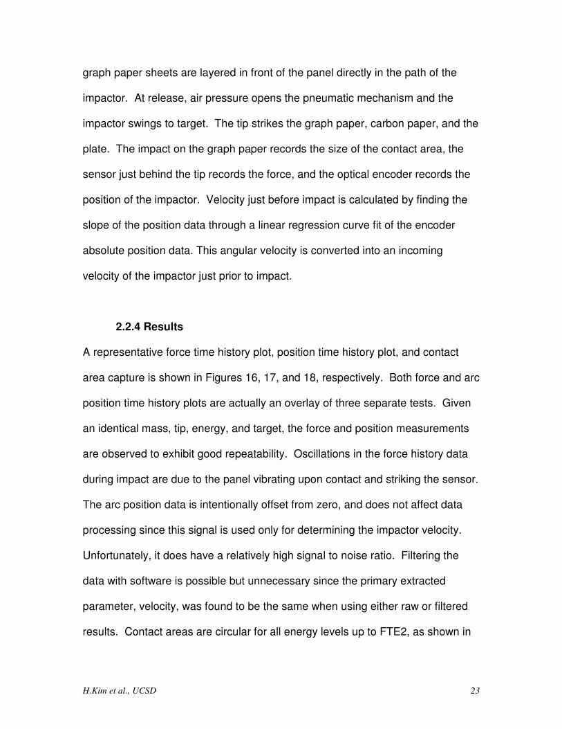
graph paper sheets are layered in front of the panel directly in the path of the
impactor. At release, air pressure opens the pneumatic mechanism and the
impactor swings to target. The tip strikes the graph paper, carbon paper, and the
plate. The impact on the graph paper records the size of the contact area, the
sensor just behind the tip records the force, and the optical encoder records the
position of the impactor. Velocity just before impact is calculated by finding the
slope of the position data through a linear regression curve fit of the encoder
absolute position data. This angular velocity is converted into an incoming
velocity of the impactor just prior to impact.
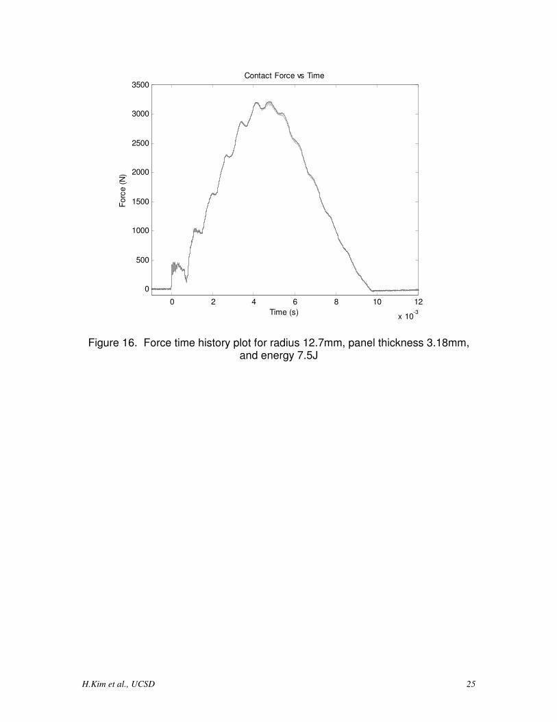
2.2.4 Results A representative force time history plot, position time history plot, and contact
area capture is shown in Figures 16, 17, and 18, respectively. Both force and arc
position time history plots are actually an overlay of three separate tests. Given
an identical mass, tip, energy, and target, the force and position measurements
are observed to exhibit good repeatability. Oscillations in the force history data
during impact are due to the panel vibrating upon contact and striking the sensor.
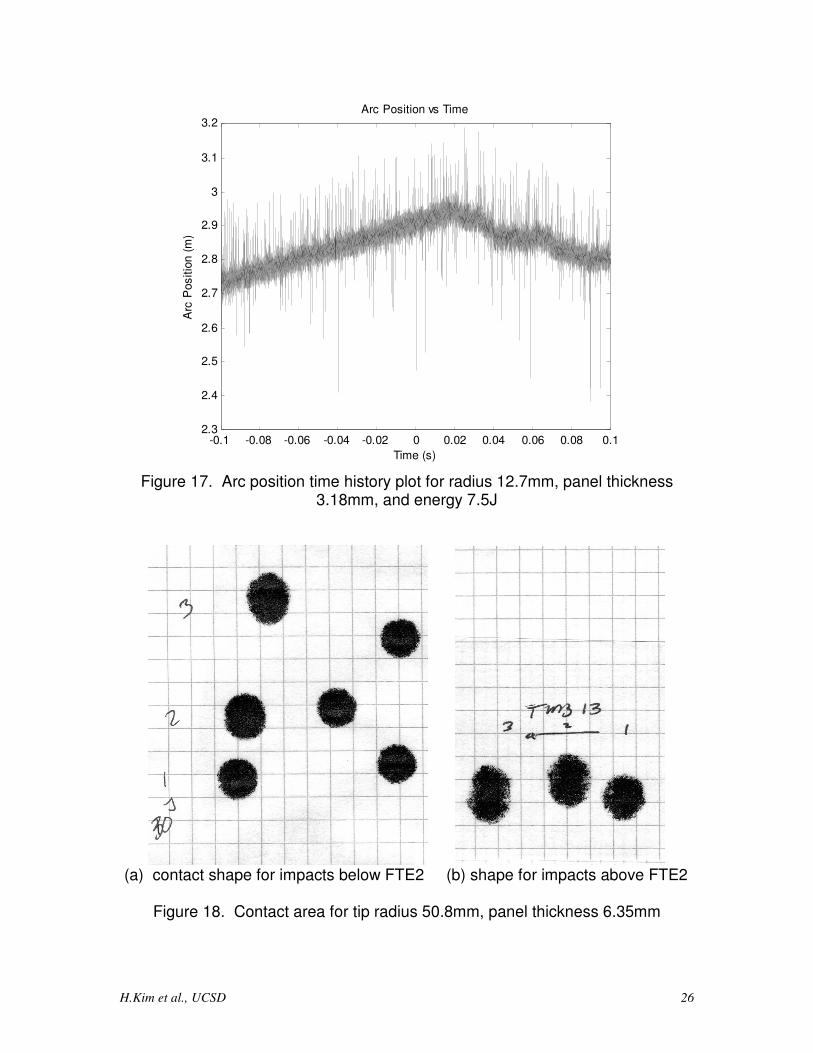
The arc position data is intentionally offset from zero, and does not affect data
processing since this signal is used only for determining the impactor velocity.
Unfortunately, it does have a relatively high signal to noise ratio. Filtering the
data with software is possible but unnecessary since the primary extracted
parameter, velocity, was found to be the same when using either raw or filtered
results. Contact areas are circular for all energy levels up to FTE2, as shown in

H.Kim et al., UCSD 24
Figure 18a, with no observable changes at FTE1. At FTE2, the contact area
changes from a circle to a "peanut" like shape (see Figure b). This progression
is confirmed by Davies and Zhang [4], who attribute the interlaminar
delaminations to high bending strains.
The failure threshold energy is observed to increase with increasing panel
thickness and tip radius. FTE2 is not reached by the 152.4mm impactor at
energy levels of 40J. See Table 3. It is apparent that for a given energy level,
two impactors differing only in their degree of bluntness may not initiate the same
damage mode. It is possible then, that a structure with visible signs of damage
may be identified and repaired accordingly, while another structure with no visible
signs of damage may not be repaired, even though they were both subject to the
same impact energy. Also, to initiate a given damage mode, a blunter impactor
needs more energy than a sharper impactor. However, as the energy level
increases, the entire test frame is increasingly involved in the target dynamic
response, thereby affecting the build up of local contact forces on the panel. At
higher energy levels, the frame experiences a substantial amount of deflection as
it attempts to react the impactor energy. It is possible then, for two structures
with visible signs of damage that one may have only local damage in immediate
area whereas the other may have global damage in locations away from the
impact.
H.Kim et al., UCSD 25
0 2 4 6 8 10 12
x 10-3
0
500
1000
1500
2000
2500
3000
3500Contact Force vs Time
Time (s)
Forc
e (
N)
Figure 16. Force time history plot for radius 12.7mm, panel thickness 3.18mm, and energy 7.5J
H.Kim et al., UCSD 26
-0.1 -0.08 -0.06 -0.04 -0.02 0 0.02 0.04 0.06 0.08 0.12.3
2.4
2.5
2.6
2.7
2.8
2.9
3
3.1
3.2Arc Position vs Time
Time (s)
Arc
Positio
n (
m)
Figure 17. Arc position time history plot for radius 12.7mm, panel thickness
3.18mm, and energy 7.5J
(a) contact shape for impacts below FTE2 (b) shape for impacts above FTE2
Figure 18. Contact area for tip radius 50.8mm, panel thickness 6.35mm
H.Kim et al., UCSD 27
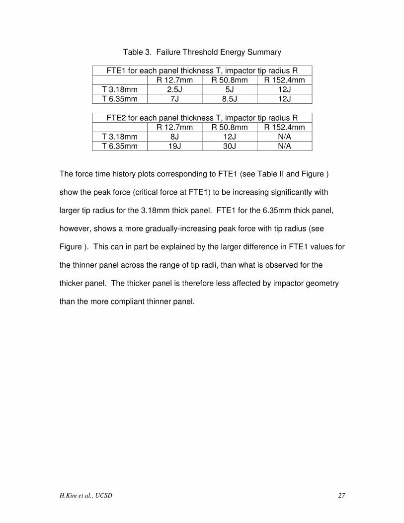
Table 3. Failure Threshold Energy Summary
FTE1 for each panel thickness T, impactor tip radius R R 12.7mm R 50.8mm R 152.4mm
T 3.18mm 2.5J 5J 12J T 6.35mm 7J 8.5J 12J
FTE2 for each panel thickness T, impactor tip radius R
R 12.7mm R 50.8mm R 152.4mm T 3.18mm 8J 12J N/A T 6.35mm 19J 30J N/A
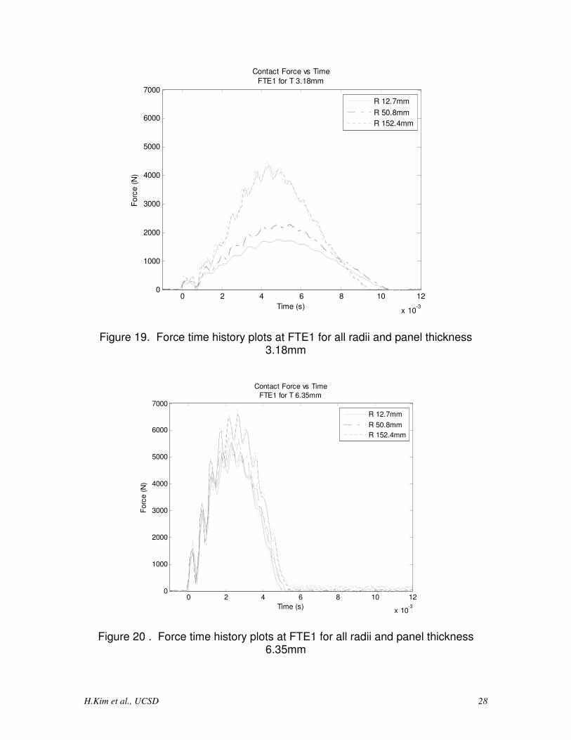
The force time history plots corresponding to FTE1 (see Table II and Figure )
show the peak force (critical force at FTE1) to be increasing significantly with
larger tip radius for the 3.18mm thick panel. FTE1 for the 6.35mm thick panel,
however, shows a more gradually-increasing peak force with tip radius (see
Figure ). This can in part be explained by the larger difference in FTE1 values for
the thinner panel across the range of tip radii, than what is observed for the
thicker panel. The thicker panel is therefore less affected by impactor geometry
than the more compliant thinner panel.
H.Kim et al., UCSD 28
0 2 4 6 8 10 12
x 10-3
0
1000
2000
3000
4000
5000
6000
7000
Time (s)
Forc
e (
N)
Contact Force vs Time
FTE1 for T 3.18mm
R 12.7mm
R 50.8mm
R 152.4mm
Figure 19. Force time history plots at FTE1 for all radii and panel thickness 3.18mm
0 2 4 6 8 10 12
x 10-3
0
1000
2000
3000
4000
5000
6000
7000
Time (s)
Forc
e (
N)
Contact Force vs Time
FTE1 for T 6.35mm
R 12.7mm
R 50.8mm
R 152.4mm
Figure 20 . Force time history plots at FTE1 for all radii and panel thickness 6.35mm

H.Kim et al., UCSD 29
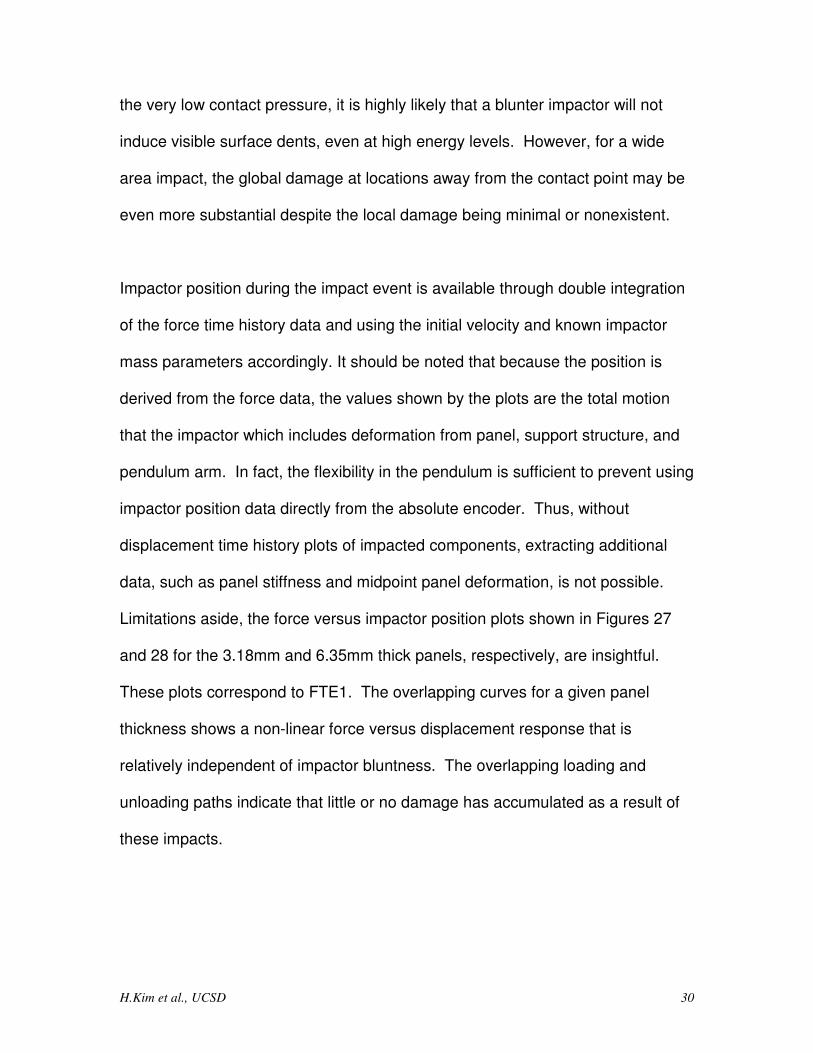
The contact area for both panel thicknesses appears to be roughly linearly
proportional to impact energy. See Figures 21 and 22 for the 3.18 and 6.35 mm
thick panels, respectively. The closed symbols indicate measurements
corresponding to no damage being formed (i.e., lower energy levels below
FTE1), while the large open symbols indicate measurements following damage
initiation. As expected, the larger radius impactor tips develop higher contact
areas. The contact area is dramatically higher for the thin panels and for a given
tip radius. This observation can be attributed to the ability of the thin panel to
locally deform and conform to the impactor tip geometry more easily than the
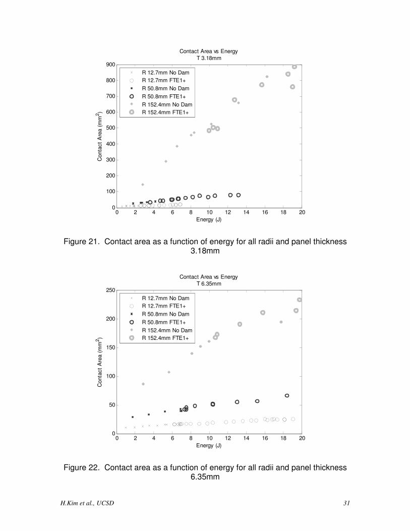
thick panel. Contact force is found to vary proportionally, but not linearly, with
energy. Since stiffness is a characteristic of the panel system, the peak contact
forces for all radii for a given panel thickness fall on the same curve, as shown in
Figures 23 and 24. The contact forces generated for impacts onto the thick
panel is significantly larger than for the thin panel, due to the relatively higher
transverse stiffness of the thick panel. Greater peak contact forces are
developed, in general, for more rigid impact conditions.
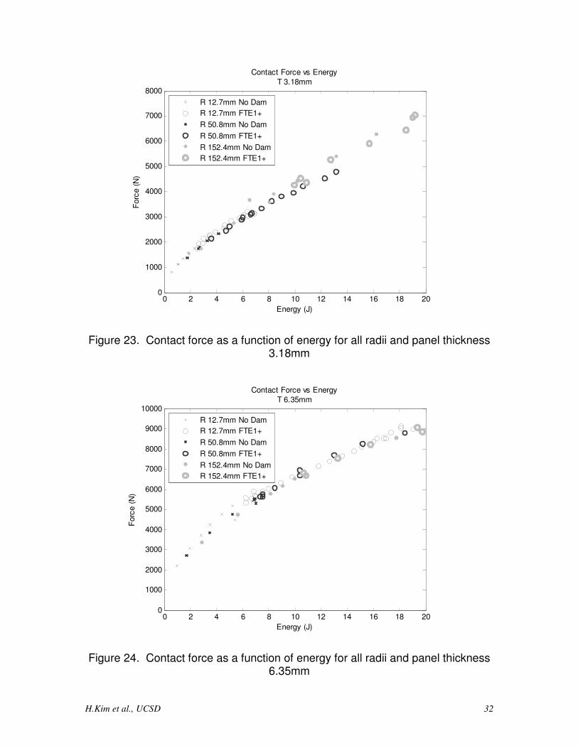
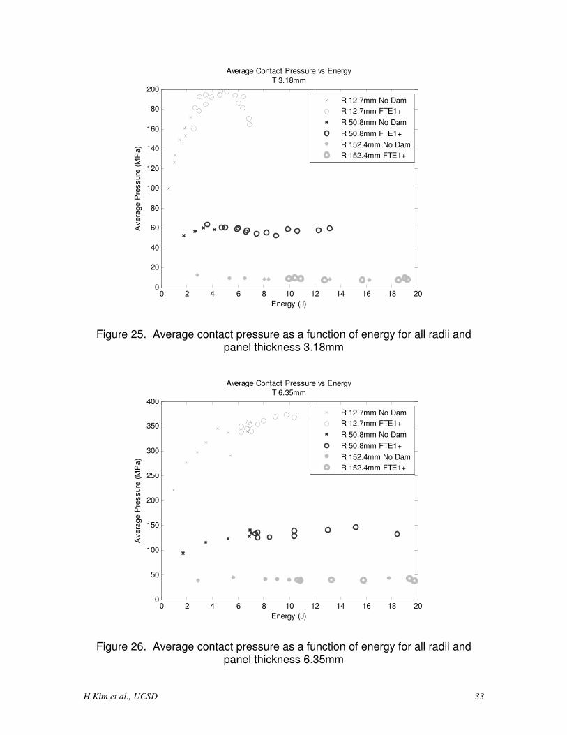
Dividing the force by contact area to obtain the average contact pressure and
plotting this quantity against energy shows trends not readily visible in either the
force or area plots examined separately. Plotted in Figures 25 and 26, the
average contact pressure for a given radius is observed to increase until it peaks
around FTE1, and then decrease thereafter. Contact pressure is substantially
lower for the 152.4mm tip when compared with the other two radii. Considering
H.Kim et al., UCSD 30
the very low contact pressure, it is highly likely that a blunter impactor will not
induce visible surface dents, even at high energy levels. However, for a wide
area impact, the global damage at locations away from the contact point may be
even more substantial despite the local damage being minimal or nonexistent.
Impactor position during the impact event is available through double integration
of the force time history data and using the initial velocity and known impactor
mass parameters accordingly. It should be noted that because the position is
derived from the force data, the values shown by the plots are the total motion
that the impactor which includes deformation from panel, support structure, and
pendulum arm. In fact, the flexibility in the pendulum is sufficient to prevent using
impactor position data directly from the absolute encoder. Thus, without
displacement time history plots of impacted components, extracting additional
data, such as panel stiffness and midpoint panel deformation, is not possible.
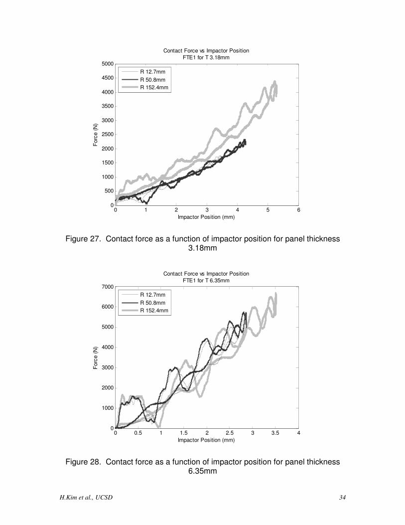
Limitations aside, the force versus impactor position plots shown in Figures 27
and 28 for the 3.18mm and 6.35mm thick panels, respectively, are insightful.
These plots correspond to FTE1. The overlapping curves for a given panel
thickness shows a non-linear force versus displacement response that is
relatively independent of impactor bluntness. The overlapping loading and
unloading paths indicate that little or no damage has accumulated as a result of
these impacts.
H.Kim et al., UCSD 31
0 2 4 6 8 10 12 14 16 18 200
100
200
300
400
500
600
700
800
900
Energy (J)
Conta
ct
Are
a (
mm
2)
Contact Area vs Energy
T 3.18mm
R 12.7mm No Dam
R 12.7mm FTE1+
R 50.8mm No Dam
R 50.8mm FTE1+
R 152.4mm No Dam
R 152.4mm FTE1+
Figure 21. Contact area as a function of energy for all radii and panel thickness 3.18mm
0 2 4 6 8 10 12 14 16 18 200
50
100
150
200
250
Energy (J)
Conta
ct
Are
a (
mm
2)
Contact Area vs Energy
T 6.35mm
R 12.7mm No Dam
R 12.7mm FTE1+
R 50.8mm No Dam
R 50.8mm FTE1+
R 152.4mm No Dam
R 152.4mm FTE1+
Figure 22. Contact area as a function of energy for all radii and panel thickness 6.35mm
H.Kim et al., UCSD 32
0 2 4 6 8 10 12 14 16 18 200
1000
2000
3000
4000
5000
6000
7000
8000
Energy (J)
Forc
e (
N)
Contact Force vs Energy
T 3.18mm
R 12.7mm No Dam
R 12.7mm FTE1+
R 50.8mm No Dam
R 50.8mm FTE1+
R 152.4mm No Dam
R 152.4mm FTE1+
Figure 23. Contact force as a function of energy for all radii and panel thickness 3.18mm
0 2 4 6 8 10 12 14 16 18 200
1000
2000
3000
4000
5000
6000
7000
8000
9000
10000
Energy (J)
Forc
e (
N)
Contact Force vs Energy
T 6.35mm
R 12.7mm No Dam
R 12.7mm FTE1+
R 50.8mm No Dam
R 50.8mm FTE1+
R 152.4mm No Dam
R 152.4mm FTE1+
Figure 24. Contact force as a function of energy for all radii and panel thickness 6.35mm
H.Kim et al., UCSD 33
0 2 4 6 8 10 12 14 16 18 200
20
40
60
80
100
120
140
160
180
200
Energy (J)
Avera
ge P
ressure
(M
Pa)
Average Contact Pressure vs Energy
T 3.18mm
R 12.7mm No Dam
R 12.7mm FTE1+
R 50.8mm No Dam
R 50.8mm FTE1+
R 152.4mm No Dam
R 152.4mm FTE1+
Figure 25. Average contact pressure as a function of energy for all radii and panel thickness 3.18mm
0 2 4 6 8 10 12 14 16 18 200
50
100
150
200
250
300
350
400
Energy (J)
Avera
ge P
ressure
(M
Pa)
Average Contact Pressure vs Energy
T 6.35mm
R 12.7mm No Dam
R 12.7mm FTE1+
R 50.8mm No Dam
R 50.8mm FTE1+
R 152.4mm No Dam
R 152.4mm FTE1+
Figure 26. Average contact pressure as a function of energy for all radii and panel thickness 6.35mm
H.Kim et al., UCSD 34
0 1 2 3 4 5 60
500
1000
1500
2000
2500
3000
3500
4000
4500
5000
Impactor Position (mm)
Forc
e (
N)
Contact Force vs Impactor Position
FTE1 for T 3.18mm
R 12.7mm
R 50.8mm
R 152.4mm
Figure 27. Contact force as a function of impactor position for panel thickness 3.18mm
0 0.5 1 1.5 2 2.5 3 3.5 40
1000
2000
3000
4000
5000
6000
7000
Impactor Position (mm)
Forc
e (
N)
Contact Force vs Impactor Position
FTE1 for T 6.35mm
R 12.7mm
R 50.8mm
R 152.4mm
Figure 28. Contact force as a function of impactor position for panel thickness 6.35mm
H.Kim et al., UCSD 35
2.2.5 Conclusions
Laboratory testing of composite panels highlight several trends in impact damage
formation with low velocity, blunt impactors. To create damage, a blunted
impactor requires significantly more energy than a sharper impactor. Thicker
panels are less affected by bluntness than thinner panels. A method for
measuring contact area is described and has been found to show an
approximately linearly relationship between contact area and energy. The
contact area is much higher for thinner panels which are able to locally deform
and therefore develop more contact with the impactor tip. Contact area
measurements allow the determination of an average contact pressure. As
expected, the peak average contact pressure is measured to be significantly
lower for a blunted impactor. When plotted against impact energy, the contact
pressure reveals an inflection point corresponding to the onset of FTE1. This
implies a softening of the contact interaction between the impactor and target
panel as delamination damage is formed. The inflection point , which is not
readily visible in either force or contact area plots, can be used for identifying the
onset of FTE1 in the smaller radius impact tips. For the largest radius tip (152.4
mm) no inflection in the average contact pressure versus energy relationship was
observed.
2.3 Hail Ice Impact
UCSD and Sandia Labs (point of contact: Dennis Roach) are collaborating on a
project focused on development of damage to carbon/epoxy composite panels of
H.Kim et al., UCSD 36
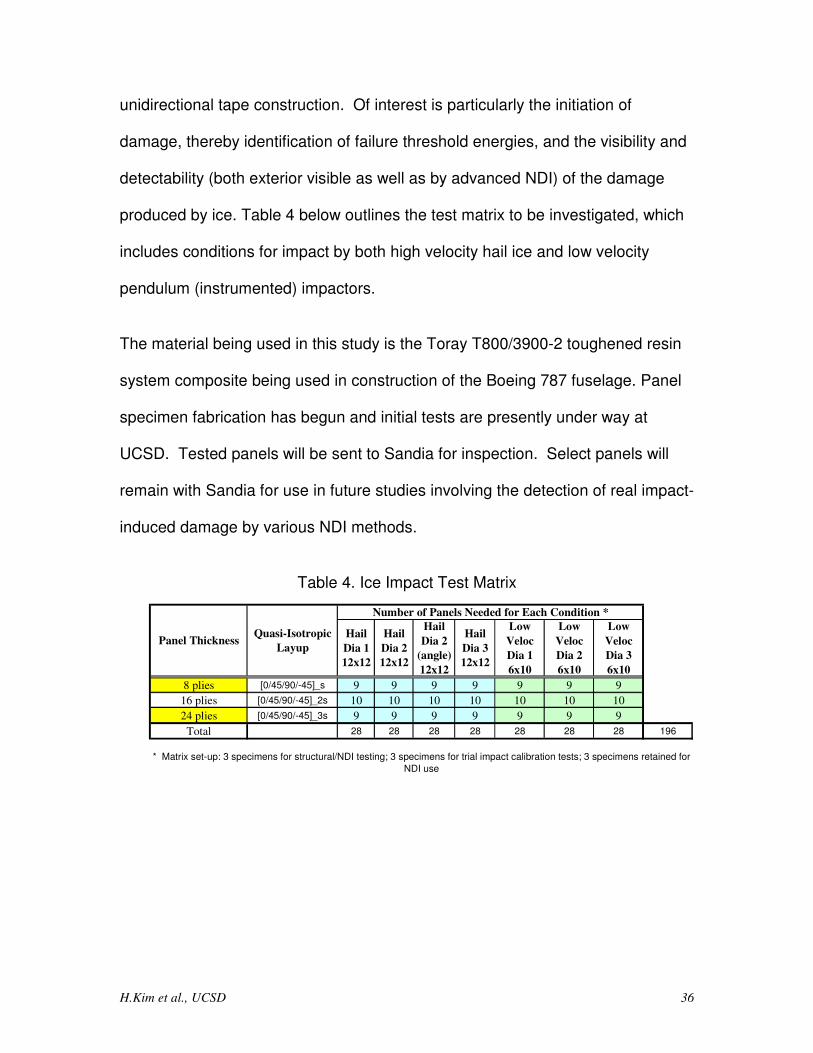
unidirectional tape construction. Of interest is particularly the initiation of
damage, thereby identification of failure threshold energies, and the visibility and
detectability (both exterior visible as well as by advanced NDI) of the damage
produced by ice. Table 4 below outlines the test matrix to be investigated, which
includes conditions for impact by both high velocity hail ice and low velocity
pendulum (instrumented) impactors.
The material being used in this study is the Toray T800/3900-2 toughened resin
system composite being used in construction of the Boeing 787 fuselage. Panel
specimen fabrication has begun and initial tests are presently under way at
UCSD. Tested panels will be sent to Sandia for inspection. Select panels will
remain with Sandia for use in future studies involving the detection of real impact-
induced damage by various NDI methods.
Table 4. Ice Impact Test Matrix
8 plies [0/45/90/-45]_s 9 9 9 9 9 9 9
16 plies [0/45/90/-45]_2s 10 10 10 10 10 10 10
24 plies [0/45/90/-45]_3s 9 9 9 9 9 9 9
Total 28 28 28 28 28 28 28 196
* Matrix set-up: 3 specimens for structural/NDI testing; 3 specimens for trial impact calibration tests; 3 specimens retained for
NDI use
Low
Veloc
Dia 3
6x10
Quasi-Isotropic
Layup
Number of Panels Needed for Each Condition *
Hail
Dia 1
12x12
Hail
Dia 2
12x12
Hail
Dia 2
(angle)
12x12
Hail
Dia 3
12x12
Low
Veloc
Dia 1
6x10
Low
Veloc
Dia 2
6x10
Panel Thickness
H.Kim et al., UCSD 37
3.0 References
1. Kim, H. and Kedward, K. T., “Modeling Hail Ice Impacts and Predicting
Impact Damage Initiation in Composite Structures,” AIAA Journal, Vol. 38,
No. 7, 2000, pp. 1278-1288.
2. Kim, H., Kedward, K.T., and Welch, D.A., “Experimental Investigation of
High Velocity Ice Impacts on Woven Carbon/Epoxy Composite Panels,”
Composites Part A, Vol. 34, No. 1, 2003, pp. 25-41.
3. Wardle, B.L., Lagace, P.A., “On the use of Quasi-Static Testing to Assess
Impact Damage Resistance of Composite Shell Structures,” Mechanics of
Composite Materials and Structures, Vol.5, No. 1, 1998, pp. 103-121.
4. Davies, G. A. O. and X. Zhang. 1993. "Impact damage prediction in carbon
composite structures," Int. J. Impact Engineering. 16(1):149-170.