Embed Size (px)
Citation preview

Document reference IMP/001/909
Version:- 3.0 Date of Issue:- March 2014 Page 1 of 22
CAUTION! - This document may be out of date if printed
IMP/001/909 Code of Practice for Distribution System Parameters 1 Purpose
The purpose of this document is to define the parameters within which the distribution systems of Northern Powergrid (Northeast) Ltd and Northern Powergrid (Yorkshire) plc, the licensed distributors of Northern Powergrid will operate. This document also describes, at a high level, how the system is designed to operate within acceptable margins of these parameters, and sets out to provide clarity with respect to evolving practices and the alignment of legacy policies across the group.
This policy helps to ensure the company meets its obligations under the Electricity Act 1989 (as amended by the Utilities Act 2000), the Electricity Safety, Quality and Continuity (ESQC) Regulations 2002 (including amendments)
1,
the Electricity at Work (EAW) Regulations 1989, the Health and Safety at Work Act 1974, the Distribution Licences and The Distribution Code, by laying out the distribution system parameters within which Northern Powergrid’s system will operate.
This document supersedes the following documents, all copies of which should be removed from circulation.
Ref Version Title
IMP/001/909 2.0 CoP for Distribution System Parameters
2 Scope
This document applies to the existing distribution systems of Northern Powergrid and any future modifications to them, and to all providers of connections to the distribution systems. The following system parameters are covered by this policy:
System voltages,
System phasing,
Distribution short circuit levels and clearance times,
Standard of security on the distribution systems,
Power Frequency and Lightning Impulse Withstand to Earth Tests.
As distribution systems develop through new connections, refurbishment of existing assets and reinforcement, consideration should be given to the harmonisation of operating parameters when it is economic to do so in order to improve safety, cost, security of supply and operational performance. For example, rationalising voltages to
1 This includes The ESQC (Amendment) Regulations 2006 (No. 1521, 1
st October 2006) and The ESQC (Amendment)
Regulations 2009 (No. 639, 6th
April 2009)

Document reference IMP/001/909
Version:- 3.0 Date of Issue:- March 2014 Page 2 of 22
CAUTION! - This document may be out of date if printed
facilitate interconnection and hence improve security of supply. Relevant investment appraisals shall consider, as one of the options, harmonising voltages and assess the costs and benefits thereof.
The document does not include the functional requirements of new switchgear, transformers, overhead lines or cables. These will be included in policies relevant to that particular asset class.
3 Policy
3.1 Assessment of Relevant Drivers
The key internal business drivers relating to establishing distribution system parameters within which the distribution system will operate are:
Employee commitment: by establishing parameters within which the system operates and the use of adequately rated equipment to form the distribution system will ensure that employees are not exposed to risks to their health as far as reasonably practicable.
Financial strength: by defining standard parameters, financial gains may be made through economies of scale in the purchase of standard plant and the adoption of standard designs and construction techniques.
Regulatory integrity: by ensuring compliance with external regulations regarding distribution system parameters.
The external business drivers relating to distribution system parameters are detailed in the following sections.
3.1.1 Requirements of the Electricity Act 1989 (as amended)
The Electricity Act 1989 (as amended by the Utilities Act 2000) lays down the core legislative framework for Northern Powergrid’s operations as a distributor. Specifically, section 9 (i) states ‘It shall be the duty of a public electricity supplier to develop and maintain an efficient, co-ordinated and economical system of electricity supply.’
3.1.2 Requirements of the Electricity Safety, Quality and Continuity (ESQC) Regulations 2002(including amendments 2006 and 2009)
The ESQC Regulations 2002 (as amended 2006 and 2009) impose a number of obligations on the business, mainly relating to safety and quality of supply. All the requirements of the ESQC Regulations that are applicable to distribution system parameters shall be complied with, specifically:
Reg. No Extract Application to this policy
3(1)(a)
…distributors…shall ensure that their equipment is sufficient for the purposes for and the circumstances in which it is used;
The operating parameters and hence the maximum duties of plant used on the distribution system will be defined to help ensure that any plant procured is adequate for purpose.

Document reference IMP/001/909
Version:- 3.0 Date of Issue:- March 2014 Page 3 of 22
CAUTION! - This document may be out of date if printed
Reg. No Extract Application to this policy
3(1)(b)
…distributors…shall ensure that their equipment is so constructed…as to prevent danger…or interruption of supply, so far as is reasonably practicable
The prevention of danger will be achieved by defining maximum prospective short-circuit currents so that adequately rated standard plant can be purchased and used to form the distribution system.
Interruption of supply will be prevented, so far as reasonably possible, by ensuring that the normal standard of security applied is in accordance with Engineering Recommendation P2/6.
27(2)
Unless otherwise agreed in writing…the frequency shall be 50 hertz and the voltage declared in respect of a low voltage supply shall be 230 volts between the phase and neutral conductors at the supply terminals
This policy defines the nominal supply frequency and voltage.
27(3)
..the permitted variations are-
(a) a variation not exceeding 1 per cent above or below the declared frequency;
(b) in the case of a low voltage supply, a variation not exceeding 10 per cent above or 6 per cent below the declared voltage at the declared frequency;
(c) in the case of a high voltage supply operating at a voltage below 132,000 volts, a variation not exceeding 6 per cent above or below the declared voltage at the declared frequency; and
(d) in the case of a high voltage supply operating at a voltage of 132,000 volts or above, a variation not exceeding 10 per cent above or below the declared voltage at the declared frequency.
This policy defines the permitted variations in frequency and voltage.
3.1.3 Requirements of the Electricity at Work Regulations 1989
The Electricity at Work Regulations 1989 place obligations on Northern Powergrid relating to the safety of plant and equipment used on the distribution system. Regulation 4 (1), Systems, work activities and protective equipment states; ‘All systems shall at all times be of such construction as to prevent, so far as is reasonably practicable, danger’ and regulation 5, Strength and Capability of Electrical Equipment states; ‘No electrical equipment shall be put into use where its strength and capability may be exceeded in such a way as may give rise to danger.’
This policy ensures compliance by setting parameters such that suitable plant can be purchased and used to form the distribution system, hence ensuring that employees are not exposed to risks to their health as far as reasonably practicable.

Document reference IMP/001/909
Version:- 3.0 Date of Issue:- March 2014 Page 4 of 22
CAUTION! - This document may be out of date if printed
3.1.4 The Health and Safety at Work Act 1974
Section 2(1) states that ‘It shall be the duty of every employer to ensure, so far as is reasonably practicable, the health, safety and welfare at work of all his employees’. Section 3(1) also states that ‘It shall be the duty of every employer to conduct his undertaking in such a way as to ensure, so far as is reasonably practicable, that persons not in his employment who may be affected thereby are not thereby exposed to risks to their health or safety’.
This requirement is addressed in this policy through prescribing system short circuit levels to ensure that prospective short circuit current does not exceed plant rating, thus reducing exposure to risk.
3.1.5 Requirements of Distribution Licences
Each Distribution Licence holder is required to hold, maintain and comply with the GB Distribution Code. The Distribution Licences contain a number of conditions that are relevant to the establishment of system parameters. In particular, Standard Licence Condition 20 requires DNOs to comply with the GB Distribution Code which ‘is designed so as to permit the development, maintenance, and operation of an efficient, coordinated and economical system for the distribution of electricity’.
This requirement is addressed in this policy through the adoption of standard system voltages, phasing and short circuit duties, where it is economic to do so, which enables the adoption of standard plant and hence bring economies of scale. Harmonisation of feeder voltages and phasing may also provide cost-effective interconnection of existing systems and thus improve security of supply.
3.2 Key Requirements
The distribution system should be developed in such a way as to:
Provide a safe working environment for employees and prevent, as far as reasonably possible, danger to employees or to the public.
Provide an acceptable level of quality, security and availability of supply.
Discharge the obligation under section 9 of the Electricity Act, ‘to develop and maintain an efficient, co-ordinated and economical system of electricity distribution’.
Provide benefits through economies of scale during purchasing. By establishing standard parameters, a standardised suite of plant may be requisitioned which may be applied to any part of the distribution system and will operate within the specified parameters.
Achieve harmonisation of voltage and phasing where the opportunity arises and it is economical to do so, and if it will create additional transfer capacity e.g. by upgrading an isolated 6kV network surrounded by 11kV networks.

Document reference IMP/001/909
Version:- 3.0 Date of Issue:- March 2014 Page 5 of 22
CAUTION! - This document may be out of date if printed
3.3 General Requirements
All plant used on the distribution system must be capable of safe operation under all anticipated operating conditions and duties within the expected range of climatic conditions and within the distribution system parameters set out in the table below.
Table 1: General distribution system parameters
Parameter LV 11kV 20kV 33kV 66kV 132kV Units
Nominal voltage 0.23/0.4 11 20 33 66 132 kV rms
Power frequency withstand to earth 3 28 50 70 140 275 kV rms
Lightning impulse withstand to earth - 95 125 170 325 650 kV peak
Rated frequency 50 50 50 50 50 50 Hz
3 ph symmetrical short circuit current 35.5 13.1 10.1 20 20 25 kA
Neutral earthing point multiple source source source source all ends -
Earth fault factor 1.73 1.73 1.73 1.73 1.73 1.40 -
Rated voltage of plant 0.6/1 12 24 36 72.5 145 kV rms
3.4 Standard Voltages
3.4.1 Distribution Voltages
The preferred standard nominal voltages used on the distribution system are:
132kV
66kV
33kV
20kV (Northern Powergrid (Northeast) Ltd)
11kV
400/230V
Distribution voltages in the range 5.75kV - 6.6kV are non-preferred legacy voltages.

Document reference IMP/001/909
Version:- 3.0 Date of Issue:- March 2014 Page 6 of 22
CAUTION! - This document may be out of date if printed
3.4.2 Declared Voltages and frequency of Supply
Unless agreed in writing between the distributor, the supplier and the consumer (and if necessary between Northern Powergrid and any other distributor likely to be affected), the declared line voltages for supplies provided from the distribution system shall be:
132kV ± 10%
66kV ± 6%
33kV ± 6%
25kV Railway traction single phase supply ± 6%
20kV (Northern Powergrid (Northeast) Ltd) ± 6%
11kV ± 6%
400 +10/-6%
Thus, the declared phase voltage for LV supplies shall be 230V +10/-6%.
There are existing customers with supplies in the range 5.75kV - 6.6kV. Such supplies are acceptable, however when economic opportunities arise, consideration should be given to changing the supply voltage to a preferred standard voltage.
The frequency of the supply shall be 50Hz ± 1%.
3.5 System Phasing
3.5.1 Introduction
The adoption of standard phasing allows substations equipped with standard plant to be established in all localities and permits interconnection at each voltage level. This results in benefits in terms of operational safety, efficiency and security of supply.
3.5.2 Standard Vector Relationships
For the purpose of this document, Red, Yellow and Blue, or the initials R, Y and B, represent the phase vectors and not the physical colouring of cable insulation or marking thread or any other labelling of conductors or terminations.
The phase sequence at each system voltage is represented vectorially by R-Y-B anticlockwise rotation with the exception of the 11kV and LV system in the City of York and the LV (fed from 11kV) system in Middlesbrough, which are represented by R-Y-B clockwise rotation.
The standard relationships of the voltage vectors at 66kV and 33kV, in relation to the reference 132kV vector, for the Northern Powergrid (Northeast) Ltd distribution system are shown in Figure 1. Northern Powergrid (Northeast) Ltd HV and LV phasor relationships are shown in Table 2. The standard voltage vectors at 66kV, 33kV, 11kV and 0.400kV, in relation to the reference 132kV vector, for the Northern Powergrid (Yorkshire) plc distribution system are shown in Figure 2
2.
2 Interconnection at LV and HV voltages between Northern Powergrid (Northeast) Ltd and Northern Powergrid
(Yorkshire) plc is unlikely to be viable because of the phase differences. Interconnection at 66kV would require a 90° phase shift. Interconnection at 33kV is most tenable since this could be achieved by rolling the connections.

Document reference IMP/001/909
Version:- 3.0 Date of Issue:- March 2014 Page 7 of 22
CAUTION! - This document may be out of date if printed
Table 2: Northern Powergrid (Northeast) Ltd HV and LV Phasor Relationships
Voltage (kV)
20kV System
11kV System
6kV Systems
Darlington 6kV
Sunderland 5kV
York NESCo Middlesbrough
20kV 11kV
HV 0° +30° +30° +90° +30° +120°R +30° 0° +30°
LV −30° +60° +60° +120° +60° +90°R 0° +30° −60°R
400kV, 275kV, 132kV and 66kV Voltage Vectors
R 0° Y −120° B +120°
33kV Voltage Vectors R −30° Y −150° B +90°
R
Y
B
R
B
Y
Figure 1: Northern Powergrid (Northeast) Ltd 132kV and EHV Vector Relationships.

Document reference IMP/001/909
Version:- 3.0 Date of Issue:- March 2014 Page 8 of 22
CAUTION! - This document may be out of date if printed
3.5.3 Phase Identification and Connections
Phase relationships for the Northern Powergrid (Northeast) Ltd high voltage system are shown in Appendix 1a and Northern Powergrid (Northeast) Ltd low voltage phase relationships are shown in Appendix 1b. Standard phasing and phase connections for switchgear and transformers to the Northern Powergrid (Yorkshire) plc system are shown in Appendix 2a and 2b.
400kV, 275kV and 132kV Voltage Vectors
R 0° Y −120° B +120°
66kV and 33kV and 11kV Voltage Vectors R +90° Y −30° B −150°
0.400kV Voltage Vectors R +120° Y 0° B −120°
R
Y
B
Y
R
B
R
B
Y
Figure 2: Northern Powergrid (Yorkshire) plc Standard Vector Relationships

Document reference IMP/001/909
Version:- 3.0 Date of Issue:- March 2014 Page 9 of 22
CAUTION! - This document may be out of date if printed
3.5.4 Marking of Busbars and Main Connections
The switchgear used on the distribution system shall have busbars and main connections marked in accordance with BS 159:1992, which states that busbars which are substantially in one plane shall be arranged in the sequence in which the phase voltages rise. Where the equipment of which they form a part has a clearly defined front or operating face the first phase, or red phase to UK practice, shall be positioned as follows:
a) When the run of the conductors is horizontal, the red shall be the top, or the left or farthest away as viewed from the front.
b) When the run of the conductors is vertical, the red shall be the left or farthest away as viewed from the front.
c) When the system has a neutral connection in the same plane as the phase connections, the neutral shall occupy an outer position.
Unless the neutral connection can be readily distinguished from the phase connections, the order shall be red, yellow, blue, black.
Note that the colours; Red, Yellow and Blue, or the initials R, Y and B, represent the phase vectors and not the physical colouring of the cable insulation or marking thread or any other labelling of conductors or terminations.
Outdoor switchgear requires individual consideration and, where necessary, a diagram specifying the phasing and phase connections shall be prepared for the individual project.
3.5.5 Transformer Terminals and Phase Connections
The red phase vector on the 132kV system is the reference vector for phasing on the distribution system, and is in phase with the red phase vector on the 400kV and 275kV systems, all of which are taken to be at 0º. The phase connection of the terminals of a three phase transformer shall be as indicated in Tables a- g in Appendix 3.
Transformers shall be connected with the minimum crossings to achieve the required system phasing. A consistent method of connection shall be laid down within each operational area for each type of non-standard EHV or HV/LV transformer. Details of non-standard connections should be recorded in the notes field of the appropriate asset register.
3.5.6 Implementation on 11kV, 20kV and LV Systems
When new substations or three phase pole equipments are being introduced, or when major alterations are carried out on existing non-standard distribution systems, phasing and phase connections shall be used in accordance with the respective Northern Powergrid (Northeast) Ltd/Northern Powergrid (Yorkshire) plc standard, provided it is economical to convert sufficient adjacent non-standard substations or pole equipments to maintain the requisite degree of interconnection and security in the area.
The only acceptable exception to the above is where a new substation is to be introduced into an 11kV feeder in which a group of substations with identical non-standard connections could, at a later date, be converted to standard phasing by making one or two phasing-out straight joints only. With this method, no other work would be required on the equipment at any of the group of substations, except for changing the colour marking on plant and equipment, resulting in lower capital costs. In such a case, the new substations shall be connected in a similar way to adjacent substations following the approval of the Design Manager. A durable notice shall be posted in the new substation to indicate the actual phasing until the complete feeder is changed to standard phasing.
3.5.7 Alterations at Existing Customers Premises
Where the change to standard system phasing results in a change in the phase sequence of the supply to an existing customer (HV or LV) with three phase motors, alterations must be made to the connections at the same time as the

Document reference IMP/001/909
Version:- 3.0 Date of Issue:- March 2014 Page 10 of 22
CAUTION! - This document may be out of date if printed
system connections are changed in order to avoid incorrect rotation of motors. Reversal of the phasing to restore correct rotation shall normally be made by interchanging two of the incoming phases at the customer’s intake point with suitable identification made on all phases.
To ensure that there is no adverse impact on metering equipment, the appointed metering agent should be informed, through liaison with the customer and electricity supplier, of any proposed changes to system phasing.
3.6 Short Circuit Levels
3.6.1 Introduction
The impedance of the system is the important factor which determines the maximum prospective short circuit current and hence the rating of equipment to be used on the system.
The selection of prospective system short circuit current is a balance between several factors; a high fault level maintains power quality standards to customers by reducing flicker and ensures fast operation of protection, conversely, a low fault level reduces the safety implications of a fault and limits damage to equipment. In practice this balance results in short circuit levels which are towards the upper end of the rating of the substation equipment.
Both customers’ and distribution plant must be adequately rated for the maximum prospective short-circuit current which may include a back-feed component from rotating plant including embedded generation.
3.6.2 Maximum Prospective System Short-Circuit Currents
The range of 132kV switchgear currently obtainable typically has a maximum short circuit rating of up to 40kA 3-phase, 40kA single phase to earth. This rating may be needed at Grid Supply Points where more than two 400 or 275/132kV transformers are installed thus permitting three or more transformers to be operated in parallel to meet the required security standard.
Table 3 below outlines the maximum prospective symmetrical short-circuit currents which should be considered the normal maximum design parameters for distribution systems. For convenience the equivalent symmetrical 3 phase short-circuit level at nominal system voltage is also shown.

Document reference IMP/001/909
Version:- 3.0 Date of Issue:- March 2014 Page 11 of 22
CAUTION! - This document may be out of date if printed
Table 3: Design Short Circuit Rating
System Voltage (kV)
Present Design Maximum Prospective Short-Circuit Current Equivalent 3ph Short-
Circuit Level (MVA) 3 Phase (kA) Phase to Earth (kA)*
132 25 31.5 5700
66 20 2286
33 20 1145
20 10.1 350
11 13.1 250
6 13.1 150
0.400 35.5 25
*Note: Phase to earth currents at 66kV and below are less than 3 phase currents.
It should be recognised that there will be existing systems where the rating of the equipment is lower than the design level and may require the short circuit levels on the system to be limited to the rating of the equipment. In situations where infeed from distributed generation or customers’ plant would result in higher short circuit levels than those outlined above, and if it is not practicable to limit the current using equipment (e.g. reactors) in customers’ circuits, it may be considered appropriate to design the system for higher short circuit levels subject to the approval of the Design Manager.
The short circuit capability of cables and overhead lines are included in policies relevant to those particular asset classes, however, switchgear short circuit ratings are presented in Table 4 because of the need to give consideration to the X/R ratio of the distribution system. The break ratings and X/R ratios used to establish Table 4 are based on 2005 Fault Level Survey data.

Document reference IMP/001/909
Version:- 3.0 Date of Issue:- March 2014 Page 12 of 22
CAUTION! - This document may be out of date if printed
Table 4: Minimum Break Rating for New Switchgear
System Voltage (kV)
Minimum Break Rating for New Distribution System and Customer Switchgear
3 Phase (kA) Phase to Earth (kA) * @ X/R Ratio
132 40 14
66 31.5 14
33 31.5 14
20 20 14
11 (primary) 25 14
11 (distribution) 20 14
6 25 14
0.400 35 14
*Note: The Phase to Earth column will be populated in the next version of this policy based on ENA working group study on X/R ratios.
Note that whilst a duty of 25 kA at an X/R of 36 is generally within the anticipated performance curve of a circuit breaker rated to 40 kA at an X/R of 14, it is not certain that a breaker with the latter rating will actually deliver the required performance, as studies do not confidently support re-rating breakers by more than one step in the standard IEC preferred ratings table R10. Testing at a higher X/R ratio may therefore be required, particularly given the absolute sufficiency requirements of ESQC regulation 3.
3.6.3 Maximum Fault Clearance Times
The maximum fault clearance time which should be used to assess the short-circuit duty of items of equipment should be obtained by adding together the individual relay operating times and circuit breaker interruption times involved in clearing a fault onto the equipment in question. All the equipment that carries fault current should be able to withstand the effect of a simultaneous system fault and a malfunction of protection or switchgear. The times used should therefore normally be those for back-up protection and fault clearance and shown in Table 5.
Table 5: Normal Maximum Fault Duration
Voltage (kV) Normal Maximum Fault Duration (seconds)
132 1
EHV 2
HV 2
The time related short circuit requirements of cables and overhead lines are included in policies relevant to those particular asset classes, however, switchgear is generally type tested to carry the rated short circuit current for a

Document reference IMP/001/909
Version:- 3.0 Date of Issue:- March 2014 Page 13 of 22
CAUTION! - This document may be out of date if printed
minimum of 3 seconds, hence a maximum fault clearance time of 3 seconds should be used when specifying 6kV, 11kV, 20kV, 33kV and 66kV switchgear.
3.7 Standards of Security on the Distribution System
Standard licence condition 24 requires that we plan and develop our distribution systems to a standard of security not less than that laid down in the latest revision of Engineering Recommendation P2/6, except where otherwise approved by Ofgem.
The normal standard of security applied in the design of the distribution systems shall generally, therefore, be in accordance with the latest revision of Engineering Recommendation P2/6 – Security of Supply.
3.8 Power Frequency and Lightning Impulse Withstand to Earth Testing
The power frequency withstand voltage of a test object is a specified prospective voltage value which characterises the insulation of the asset with regard to a withstand test. The power frequency tests may be done at 50 or 60 Hz as the difference is not significant. The standard lightning impulse is a full lightning impulse having a front time of 1.2μs and a time to half value of 50μs.
For these tests the equipment must be set up as it will be in service, so far as all the main connections, earthed enclosures and insulation components are concerned. The method of carrying out the tests is the subject of BS 923-1:1990 (IEC 60060-1 1989). Corrections need to be made to the test voltage levels to correct to standard atmospheric conditions of temperature and humidity. Correction factors are given in the standards.
3.9 Assumptions
Minimum break rating for new switchgear short circuit levels stated in Table 4 are based on findings of the 2005 Fault Level Survey. It is envisaged that these values will be reviewed in the next version of the policy based on findings of the ENA work group.
The 132kV phase to earth column in table 4 will be populated in the next edition of the policy based on the ENA findings. It is also recognised that further guidance is required with regard to time limits for both three phase symmetrical and earth faults.
4 References
4.1 External Documentation
Reference Title Version and date
BS 159 High-voltage busbars and busbar connections 1992 BS EN62271-100 HV switchgear and controlgear, HV AC circuit breakers 2001 BS 7671 IET Wiring Regulations 2008
ER G5/4 Planning levels for harmonic voltage distortion & the connection of non-linear equipment to transmission systems and distribution networks in the UK
Issue 4 2006
ER P28 Planning limits for voltage fluctuations caused by industrial, commercial and domestic equipment in the UK
Issue 1 1989
ER P29 Planning limits for voltage unbalance in the UK for 132kV and below
Issue 1 1990
ENATS 35-1 Distribution Transformers (from 16kVA to 1000kVA) Issue 5 2007 ER P2/6 Engineering Recommendation P2/6, Security of Supply Issue 2 2006

Document reference IMP/001/909
Version:- 3.0 Date of Issue:- March 2014 Page 14 of 22
CAUTION! - This document may be out of date if printed
ER P25/1
The short-circuit characteristics of Public Electricity Suppliers’ low voltage distribution networks and the co-ordination of overcurrent protective devices on 230V single-phase supplies up to 100A
Issue 1 1996
ER P26 The Estimation of the maximum Prospective Short Circuit Current for 3 Phase 415V Supplies.
Issue 1 1985
Grid Code The Grid Code covers all material technical aspects relating to connections to and the operation and use of the Transmission System of the Transmission Network Operator (NGC).
Issue 5, Revision 6 November 2013
Distribution Code The Distribution Code and The Guide to the Distribution Code of Licensed Distribution Network Operators of Great Britain
Issue 21, January 2014
Gas and Electricity Markets Authority: Standard Conditions of the Electricity Distribution Licence
1st
April 2010
The Electricity Act 1989 Electricity at Work Regulations 1989
SI 2002 No. 2665 The Electricity Safety, Quality and Continuity Regulations 2002 including Amendments 2006 and 2009
The Health and Safety at Work Act 1974
4.2 Internal documentation
Title Date
Long Term Development Statement (Northern Powergrid Northeast) November 2013
Long Term Development Statement (Northern Powergrid Yorkshire) November 2013
5 Definitions
Term Definition
Northern Powergrid Northern Powergrid (Northeast) Limited and Northern Powergrid (Yorkshire) plc
Design Manager The manager appropriate to the part of the network where the policy is being applied, who is accountable for the implementation of this policy. They will ensure responsible persons are appointed to implement this policy.
Distributor The term distributor is intended to encompass operators transmitting and distributing electricity under the terms of the Electricity Act 1989 (as amended by the Utilities Act 2000)
Ofgem The Office of Gas and Electricity Markets, or its successor. Distribution Licence Standard condition of the Electricity Distribution Licence based on Electricity
Act 1989 for all electricity distributors

Document reference IMP/001/909
Version:- 3.0 Date of Issue:- March 2014 Page 15 of 22
CAUTION! - This document may be out of date if printed
6 Authority for issue
6.1 CDS Assurance
I sign to confirm that I have completed and checked this document and I am satisfied with its content and submit it for approval and authorisation.
Sign Date
Lynn Donald CDS Administrator Lynn Donald 27/02/14
6.2 Author
I sign to confirm that I have completed and checked this document and I am satisfied with its content and submit it for approval and authorisation.
Review Period - This document should be reviewed within the following time period.
Standard CDS review of 3 years
Non Standard Review Period & Reason
No Period: 1 year Reason: Major review of IMP documents planned for 2015
Sign Date
Saeed Samani System Planning Engineer Saeed Samani 26/02/14
6.3 Technical Assurance
I sign to confirm that I am satisfied with all aspects of the content and preparation of this document and submit it for approval and authorisation.
Sign Date
Alan Creighton Asset Management Engineer Alan Creighton 26/02/14
Mick Walbank System Planning Manager Mick Walbank 26/02/14
Derek Fairbairn Customer Connections Design Manager Derek Fairbairn 26/02/14
6.4 Approval
Approval is given for the content of this document.
Sign Date
Mark Nicholson Head of System Strategy Mark Nicholson 26/02/14
6.5 Authorisation
Authorisation is granted for publication of this document.
Sign Date
Mark Drye Director of Asset Management Mark Drye 26/02/14

Document reference IMP/001/909
Version:- 3.0 Date of Issue:- March 2014 Page 16 of 22
CAUTION! - This document may be out of date if printed
Appendix 1 – Northern Powergrid (Northeast) Ltd Phase Relationships
a. High Voltage Systems – Phase Relationships

Document reference IMP/001/909
Version:- 3.0 Date of Issue:- March 2014 Page 17 of 22
CAUTION! - This document may be out of date if printed
b. Low Voltage Systems – Phase Relationships
Appendix 2 – Northern Powergrid (Yorkshire) plc Plant Connections

Document reference IMP/001/909
Version:- 3.0 Date of Issue:- March 2014 Page 18 of 22
CAUTION! - This document may be out of date if printed
a. Simplified Diagram of Plant Connections (drawing No Y005M6316)
Document reference IMP/001/909
Version:- 3.0 Date of Issue:- March 2014 Page 19 of 22
CAUTION! - This document may be out of date if printed
b. Standard Arrangement of Plant and Connections (drawing No Y005M6317)
Document reference IMP/001/909
Version:- 3.0 Date of Issue:- March 2014 Page 20 of 22
CAUTION! - This document may be out of date if printed
Appendix 3
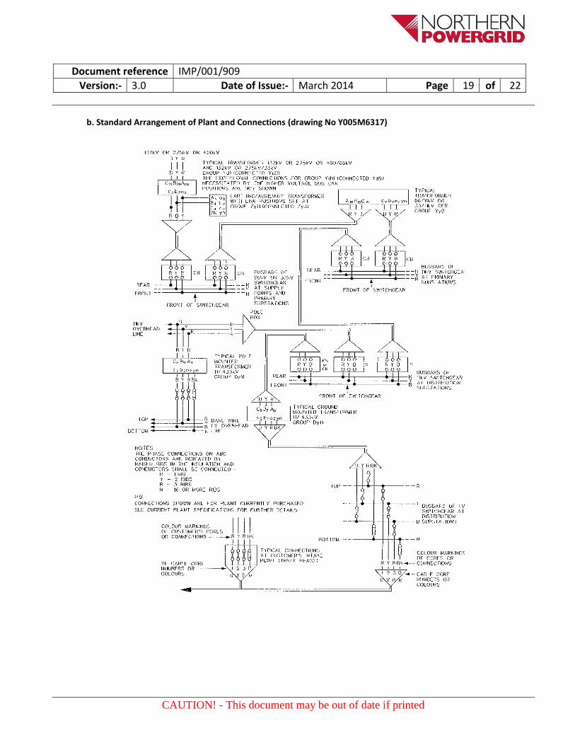
Table a: Northern Powergrid (Northeast) Ltd Standard EHV and HV Systems
Ratio (kV) Vector Group Connected as
Transformer Terminal Markings Phase shift
Primary Secondary
A B C a b c from to
132/66 Yy0 Yy0 R Y B r y b 0° 0°
132/33 Yd1 Yd1 R Y B r y b 0° -30°
Yd11 Yd1 B Y R b y r 0° -30°
132/11 Yd11 Yd11 R Y B r y b 0° +30°
66/33 Yd1 Yd1 R Y B r y b 0° -30°
Yd11 Yd1 B Y R b y r 0° -30°
66/HV Dy11 Dy11 R Y B r y b 0° +30°
33/HV Yy6 Yy10 Y B R r y b -30° +30°
Yy6 Yy10 R B Y b y r -30° +30°
33/LV Dy11 Dy9 B Y R r b y -30° +60°
HV/LV Dy11 Dy11 R Y B r y b +30° +60°
HV refers to standard 11kV systems, Tyneside3 6kV and Sunderland
4 5 kV Systems.
Table b: Northern Powergrid (Northeast) Ltd 20kV Systems
Ratio (kV) Vector Group Connected as
Transformer Terminal Markings Phase shift
Primary Secondary
A B C a b c from to
66/20 Yy0 Yy0 B Y R b y r 0° 0°
33/20 Dy11 Dy11 R Y B r y b -30° 0°
20/11 Dy11 Dy11 R Y B r y b 0° +30°
20/6 Dy11 Dy11 R Y B r y b 0° +30°
20/LV Dy11 Dy1 B Y R b y r 0° -30°
Note: This system will not parallel with others.
3 Carville/Wardley/Hebburn and Highfield South
4 Cloisters/Sunderland St Lukes/Deptford (customer sub)

Document reference IMP/001/909
Version:- 3.0 Date of Issue:- March 2014 Page 21 of 22
CAUTION! - This document may be out of date if printed
Table c: Northern Powergrid (Northeast) Ltd York5
11kV System
Ratio (kV) Vector Group Connected as
Transformer Terminal Markings Phase shift
Primary Secondary
A B C a b c from to
132/11 Yy0 Yy8 R Y B b y r 0° +120°R
B Y R r y b 0° +120°R
33/11 Dy11
Dy7 R Y B b y r -30° +120°R
Dy1 B Y R r y b -30° +120°R
11/LV Dy11 Dy11 R Y B r y b +120°R +90°R
Note: This system will not parallel with others.
Table d: Northern Powergrid (Northeast) Ltd Darlington6 6kV System
Ratio (kV) Vector Group Connected as
Transformer Terminal Markings Phase shift
Primary Secondary
A B C a b c from to
132/6 Yd1 Yd9 R Y B y b r 0° +90°
33/6 Yy0 Yy8 B R Y r y b -30° +90°
6/LV Dy11 Dy11 R Y B r y b +90° +120°
Note: This system will not parallel with others in the vicinity.
Table e: Northern Powergrid (Northeast) Ltd Middlesbrough LV System
Ratio (kV) Vector Group Connected as
Transformer Terminal Markings Phase shift
Primary Secondary
A B C a b c from to
20/LV Dy11 Dy11 R Y B r y b 0° +30°
11/LV Dy11 Dy3 R Y B y r b +30° -60°R
Note: This LV system will not parallel with others.
5 Poppleton/Melrosegate/Foss Island
6 Darlington PS/Rise Carr
Document reference IMP/001/909
Version:- 3.0 Date of Issue:- March 2014 Page 22 of 22
CAUTION! - This document may be out of date if printed
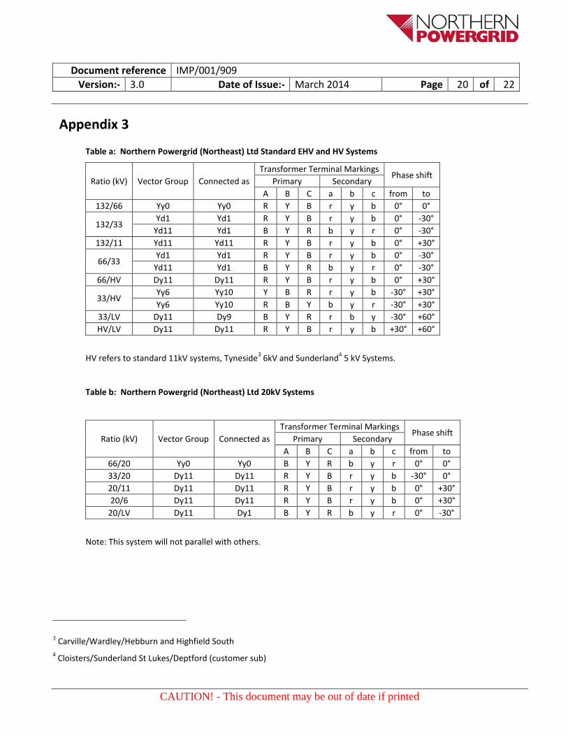
Table f: Northern Powergrid (Northeast) Ltd Ex-NESCo LV System
Ratio (kV) Vector Group Connected as
Transformer Terminal Markings Phase shift
Primary Secondary
A B C a b c from to
11/LV Dy11 Dy1 B Y R b y r +30° 0°
Note: This LV system will not parallel with others.
Table g: Northern Powergrid (Yorkshire) plc Standard Systems
Ratio (kV) Vector Group Connected as
Transformer Terminal Markings Phase shift
Primary Secondary
A B C a b c from to
132/66 Yd1 Yd9 R Y B y b r 0° +90°
132/66 Yd11 Yd9 B Y R r b y 0° +90°
132/33 Yd1 Yd9 R Y B y b r 0° +90°
132/33 Yd11 Yd9 B Y R r b y 0° +90°
132/11 Yd1 Yd9 R Y B y b r 0° +90°
132/11 Yd11 Yd9 B Y R r b y 0° +90°
66/11 Yy0 Yy0 R Y B r y b +90° +90°
33/11 Yy0 Yy0 R Y B r y b +90° +90°
11/LV Dy11 Dy11 R Y B r y b +90° +120°