Embed Size (px)
Citation preview
Service Training
Self-study Programme 370
The CrafterElectrical system
Design and function
CommercialVehicles
2
The self-study programme shows the design and function of new developments.The contents will not be updated.
For current testing, adjustment and repair instructions, refer to the relevant service literature.
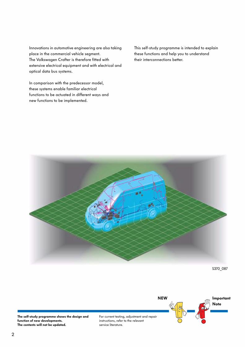
Innovations in automotive engineering are also taking place in the commercial vehicle segment. The Volkswagen Crafter is therefore fitted with extensive electrical equipment and with electrical and optical data bus systems.
In comparison with the predecessor model, these systems enable familiar electricalfunctions to be actuated in different ways and new functions to be implemented.
This self-study programme is intended to explain these functions and help you to understand their interconnections better.
S370_087
NEW ImportantNote
3
Introduction . . . . . . . . . . . . . . . . . . . . . . . . . . . . . . . . . . . . . . . . . . . . . . . . . . . 4
Vehicle electrical system. . . . . . . . . . . . . . . . . . . . . . . . . . . . . . . . . . . . . . . . 14
Ignition lock . . . . . . . . . . . . . . . . . . . . . . . . . . . . . . . . . . . . . . . . . . . . . . . . . 46
Anti-theft system . . . . . . . . . . . . . . . . . . . . . . . . . . . . . . . . . . . . . . . . . . . . . .50
Dash panel . . . . . . . . . . . . . . . . . . . . . . . . . . . . . . . . . . . . . . . . . . . . . . . . . . .56
Convenience systems . . . . . . . . . . . . . . . . . . . . . . . . . . . . . . . . . . . . . . . . . . 60
Tachograph . . . . . . . . . . . . . . . . . . . . . . . . . . . . . . . . . . . . . . . . . . . . . . . . . . . 76
Special control units . . . . . . . . . . . . . . . . . . . . . . . . . . . . . . . . . . . . . . . . . . . .78
Service . . . . . . . . . . . . . . . . . . . . . . . . . . . . . . . . . . . . . . . . . . . . . . . . . . . . . 80
Glossary. . . . . . . . . . . . . . . . . . . . . . . . . . . . . . . . . . . . . . . . . . . . . . . . . . . . . 82
Test yourself . . . . . . . . . . . . . . . . . . . . . . . . . . . . . . . . . . . . . . . . . . . . . . . . . 83
Contents
4
Introduction
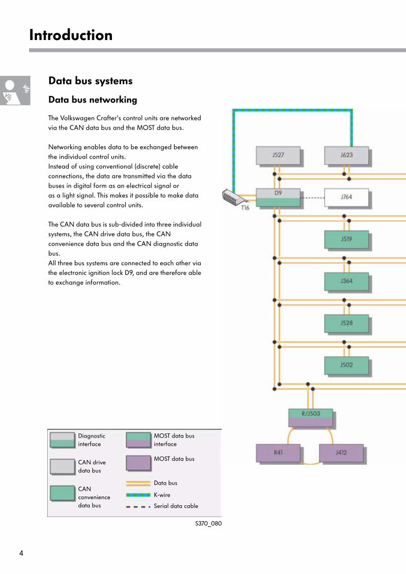
Data bus systems
Data bus networking
The Volkswagen Crafter's control units are networked via the CAN data bus and the MOST data bus.
Networking enables data to be exchanged between the individual control units.Instead of using conventional (discrete) cable connections, the data are transmitted via the data buses in digital form as an electrical signal or as a light signal. This makes it possible to make data available to several control units.
The CAN data bus is sub-divided into three individual systems, the CAN drive data bus, the CAN convenience data bus and the CAN diagnostic data bus.All three bus systems are connected to each other via the electronic ignition lock D9, and are therefore able to exchange information.
S370_080
CAN drivedata bus
CAN conveniencedata bus
Diagnosticinterface
MOST data bus
MOST data businterface
Data bus
K-wire
Serial data cable
5
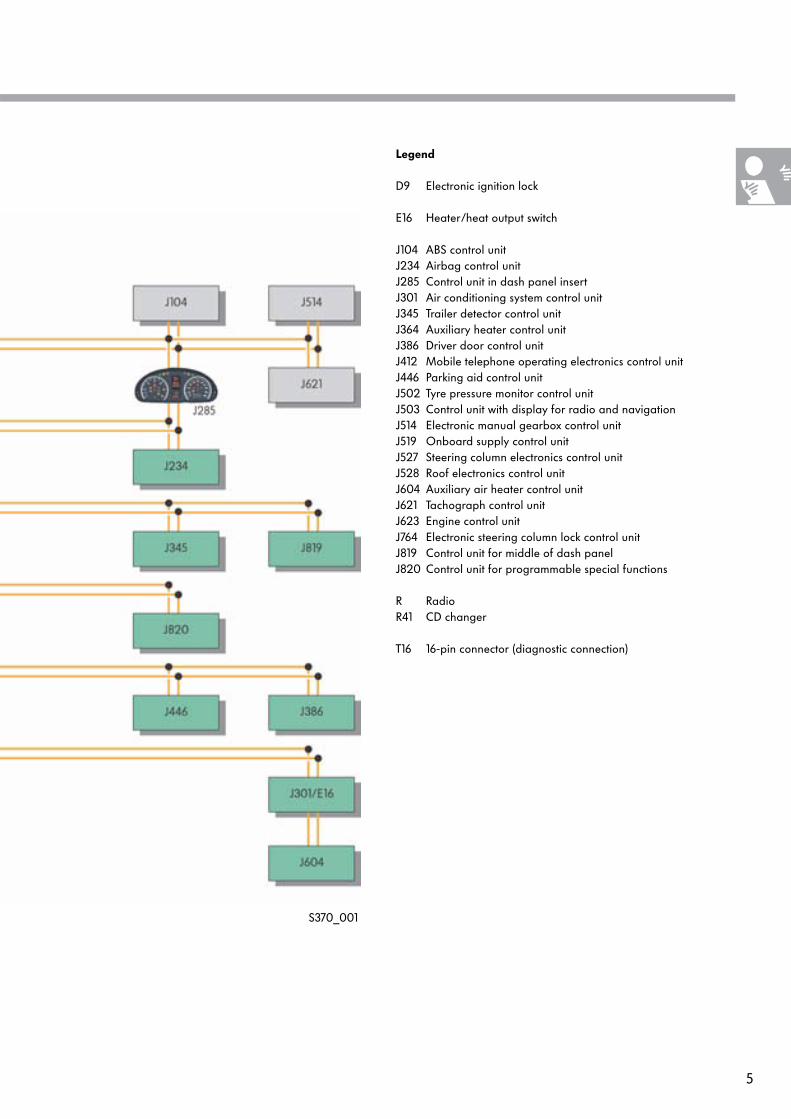
Legend
D9 Electronic ignition lock
E16 Heater/heat output switch
J104 ABS control unitJ234 Airbag control unitJ285 Control unit in dash panel insertJ301 Air conditioning system control unitJ345 Trailer detector control unitJ364 Auxiliary heater control unitJ386 Driver door control unitJ412 Mobile telephone operating electronics control unitJ446 Parking aid control unitJ502 Tyre pressure monitor control unitJ503 Control unit with display for radio and navigationJ514 Electronic manual gearbox control unitJ519 Onboard supply control unitJ527 Steering column electronics control unitJ528 Roof electronics control unitJ604 Auxiliary air heater control unitJ621 Tachograph control unitJ623 Engine control unitJ764 Electronic steering column lock control unitJ819 Control unit for middle of dash panelJ820 Control unit for programmable special functions
R RadioR41 CD changer
T16 16-pin connector (diagnostic connection)
S370_001
6
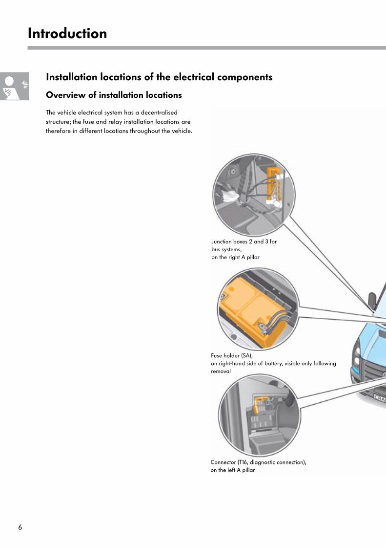
Introduction
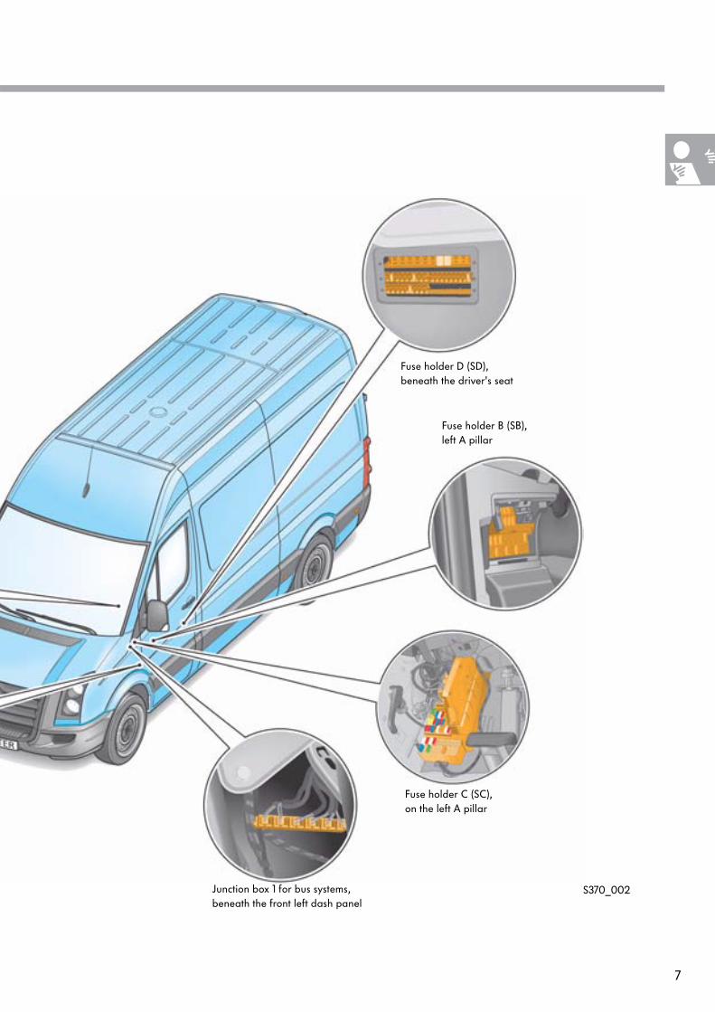
Overview of installation locations
The vehicle electrical system has a decentralised structure; the fuse and relay installation locations are therefore in different locations throughout the vehicle.
Installation locations of the electrical components
Fuse holder (SA),on right-hand side of battery, visible only following removal
Junction boxes 2 and 3 for bus systems, on the right A pillar
Connector (T16, diagnostic connection),on the left A pillar
7
S370_002Junction box 1 for bus systems,beneath the front left dash panel
Fuse holder C (SC),on the left A pillar
Fuse holder D (SD),beneath the driver's seat
Fuse holder B (SB),left A pillar
8
Introduction
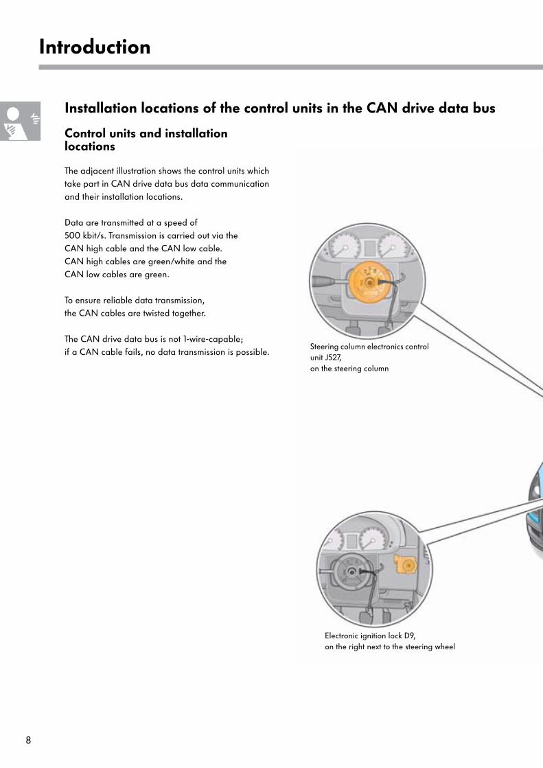
Control units and installation locations
The adjacent illustration shows the control units which take part in CAN drive data bus data communication and their installation locations.
Data are transmitted at a speed of 500 kbit/s. Transmission is carried out via the CAN high cable and the CAN low cable. CAN high cables are green/white and the CAN low cables are green.
To ensure reliable data transmission, the CAN cables are twisted together.
The CAN drive data bus is not 1-wire-capable; if a CAN cable fails, no data transmission is possible.
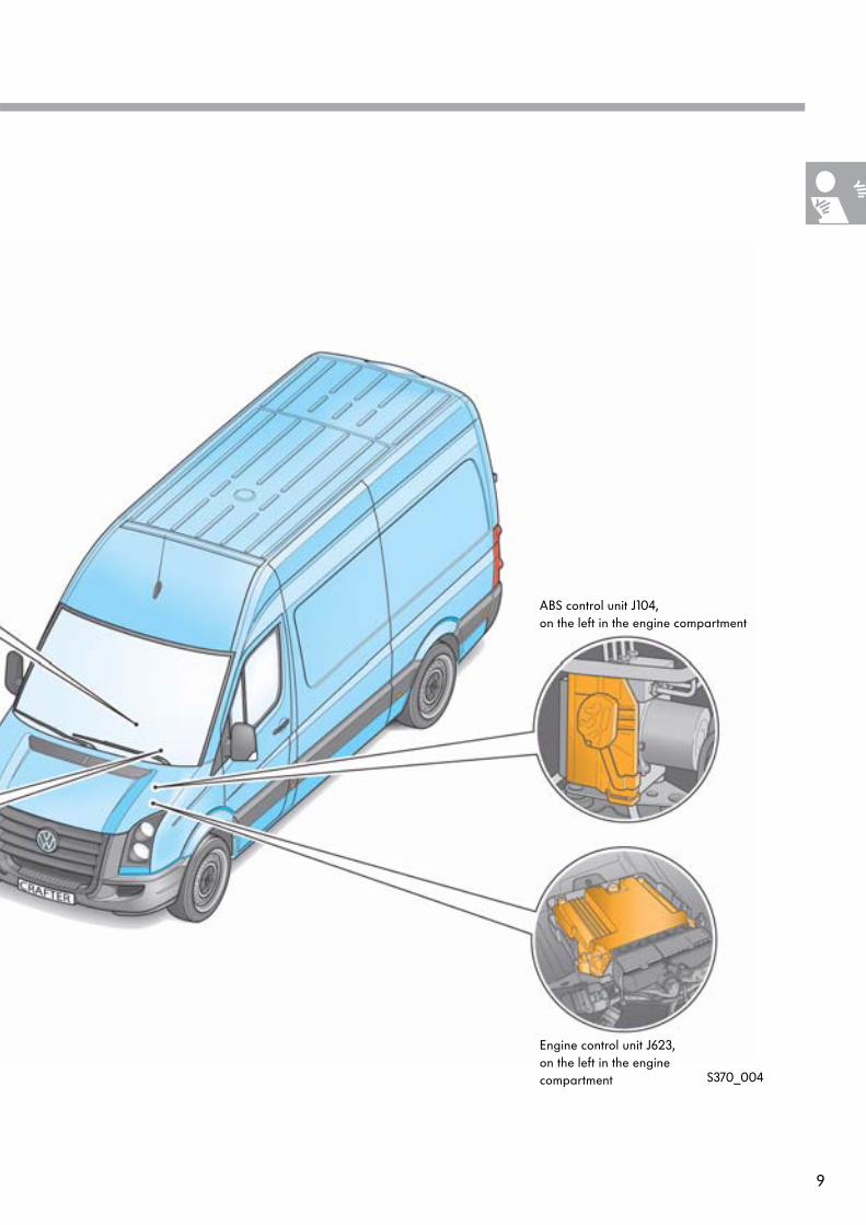
Installation locations of the control units in the CAN drive data bus
Electronic ignition lock D9,on the right next to the steering wheel
Steering column electronics control unit J527,on the steering column
9
S370_004
ABS control unit J104,on the left in the engine compartment
Engine control unit J623,on the left in the engine compartment
10
Introduction
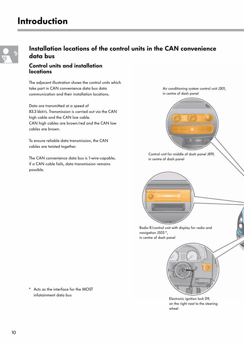
Control units and installation locations
The adjacent illustration shows the control units which take part in CAN convenience data bus data communication and their installation locations.
Data are transmitted at a speed of 83.3 kbit/s. Transmission is carried out via the CAN high cable and the CAN low cable. CAN high cables are brown/red and the CAN low cables are brown.
To ensure reliable data transmission, the CAN cables are twisted together.
The CAN convenience data bus is 1-wire-capable; if a CAN cable fails, data transmission remains possible.
Installation locations of the control units in the CAN convenience data bus
Radio R/control unit with display for radio and navigation J503 *,in centre of dash panel
Air conditioning system control unit J301,in centre of dash panel
Control unit for middle of dash panel J819,in centre of dash panel
* Acts as the interface for the MOST infotainment data bus
Electronic ignition lock D9,on the right next to the steering wheel
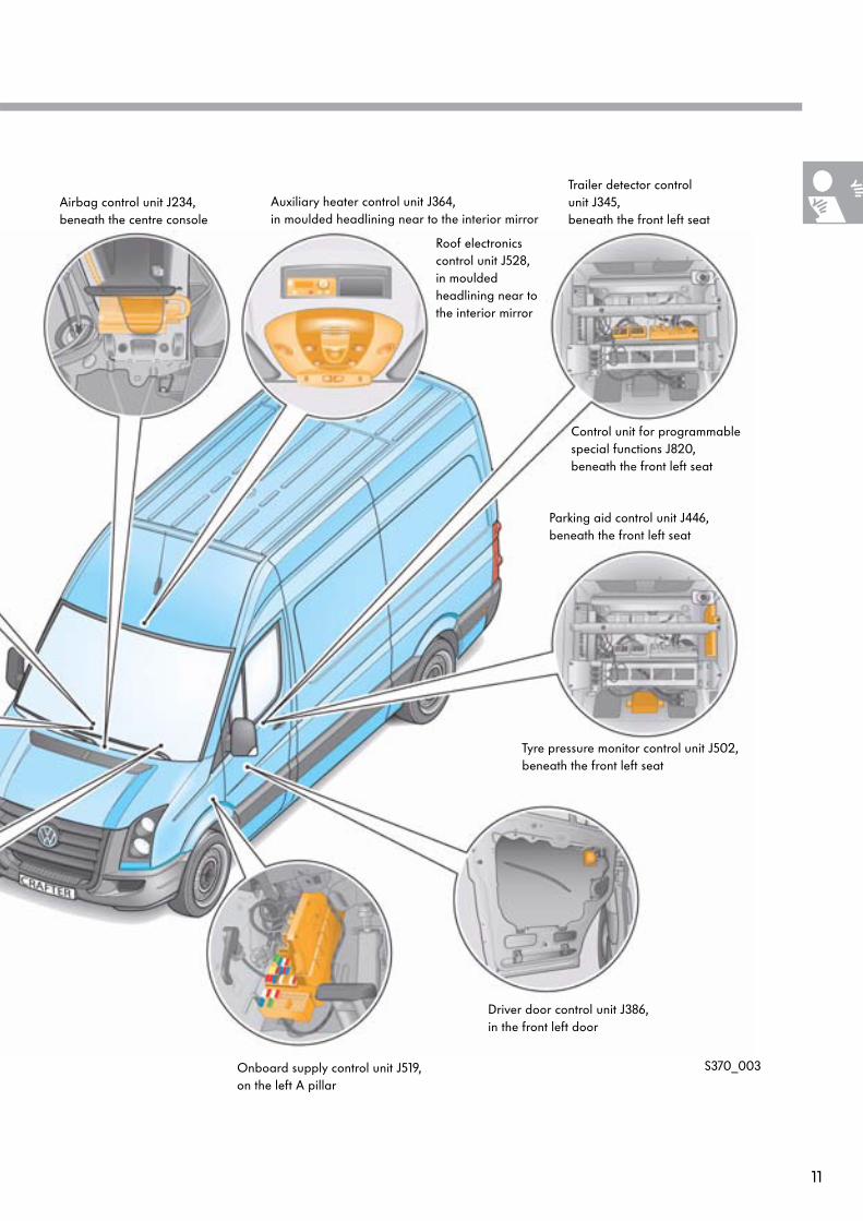
11
S370_003
Airbag control unit J234,beneath the centre console
Trailer detector control unit J345,beneath the front left seat
Tyre pressure monitor control unit J502,beneath the front left seat
Driver door control unit J386,in the front left door
Onboard supply control unit J519,on the left A pillar
Parking aid control unit J446,beneath the front left seat
Control unit for programmable special functions J820,beneath the front left seat
Auxiliary heater control unit J364, in moulded headlining near to the interior mirror
Roof electronics control unit J528,in moulded headlining near to the interior mirror
12
Introduction
Control units and installation locations
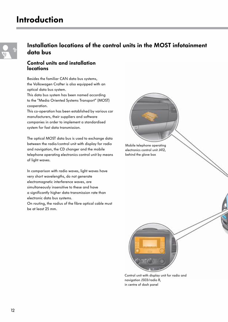
Besides the familiar CAN data bus systems, the Volkswagen Crafter is also equipped with an optical data bus system.This data bus system has been named according to the "Media Oriented Systems Transport" (MOST) cooperation. This co-operation has been established by various car manufacturers, their suppliers and software companies in order to implement a standardised system for fast data transmission.
The optical MOST data bus is used to exchange data between the radio/control unit with display for radio and navigation, the CD changer and the mobile telephone operating electronics control unit by means of light waves.
In comparison with radio waves, light waves have very short wavelengths, do not generate electromagnetic interference waves, are simultaneously insensitive to these and have a significantly higher data transmission rate than electronic data bus systems. On routing, the radius of the fibre optical cable must be at least 25 mm.
Installation locations of the control units in the MOST infotainment data bus
Mobile telephone operating electronics control unit J412,behind the glove box
Control unit with display unit for radio and navigation J503/radio R,in centre of dash panel
13
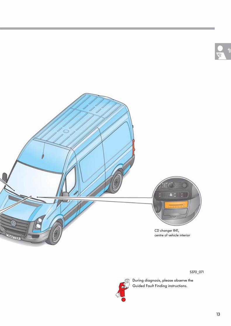
CD changer R41,centre of vehicle interior
S370_071
During diagnosis, please observe the Guided Fault Finding instructions.
14
Vehicle electrical system
Batteries
Equipment
The Volkswagen Crafter can be optionally equipped with a dual-battery vehicle electrical system; in this case, a starter and a vehicle electrical supply battery are installed.
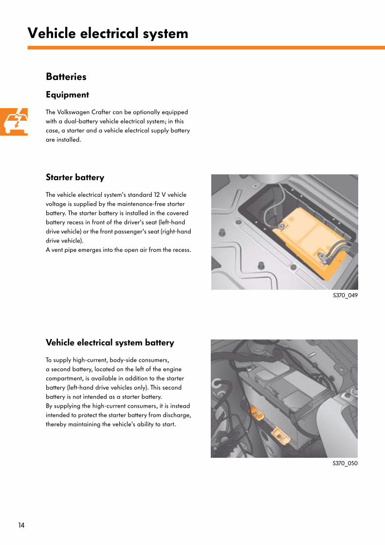
Starter battery
The vehicle electrical system's standard 12 V vehicle voltage is supplied by the maintenance-free starter battery. The starter battery is installed in the covered battery recess in front of the driver's seat (left-hand drive vehicle) or the front passenger's seat (right-hand drive vehicle). A vent pipe emerges into the open air from the recess.
Vehicle electrical system battery
To supply high-current, body-side consumers,a second battery, located on the left of the engine compartment, is available in addition to the starter battery (left-hand drive vehicles only). This second battery is not intended as a starter battery. By supplying the high-current consumers, it is instead intended to protect the starter battery from discharge, thereby maintaining the vehicle's ability to start.
S370_049
S370_050
15
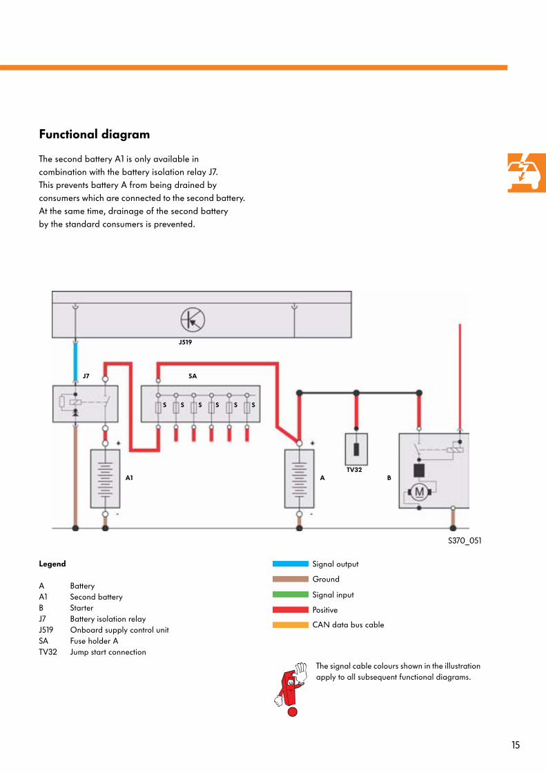
Functional diagram
The second battery A1 is only available in combination with the battery isolation relay J7. This prevents battery A from being drained by consumers which are connected to the second battery. At the same time, drainage of the second battery by the standard consumers is prevented.
S370_051
Legend
A BatteryA1 Second batteryB StarterJ7 Battery isolation relayJ519 Onboard supply control unitSA Fuse holder ATV32 Jump start connection
A1 ATV32
B
J7 SA
J519
S S S S S S
Signal output
Ground
Signal input
Positive
CAN data bus cable
The signal cable colours shown in the illustration apply to all subsequent functional diagrams.
16
Vehicle electrical system
Jump start connections
Equipment
The Volkswagen Crafter is equipped with a positive and a negative connection for jump-starting and for charging the battery.
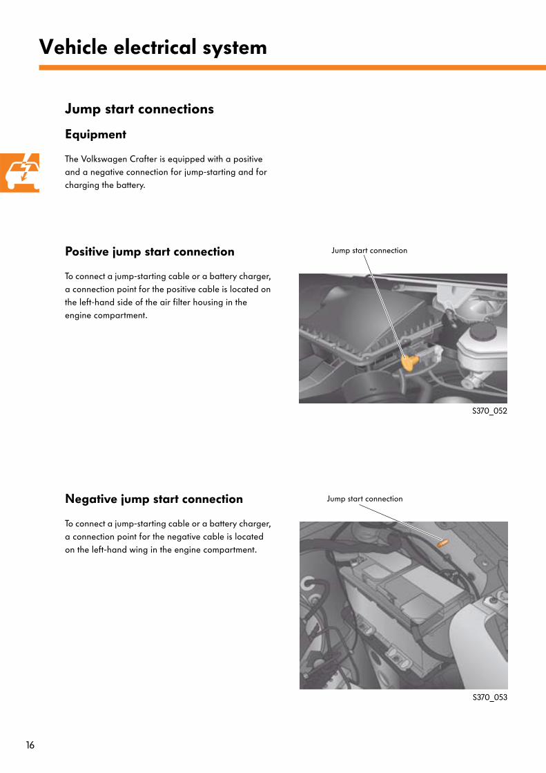
Positive jump start connection
To connect a jump-starting cable or a battery charger, a connection point for the positive cable is located on the left-hand side of the air filter housing in the engine compartment.
Negative jump start connection
To connect a jump-starting cable or a battery charger, a connection point for the negative cable is located on the left-hand wing in the engine compartment.
S370_052
S370_053
Jump start connection
Jump start connection
17
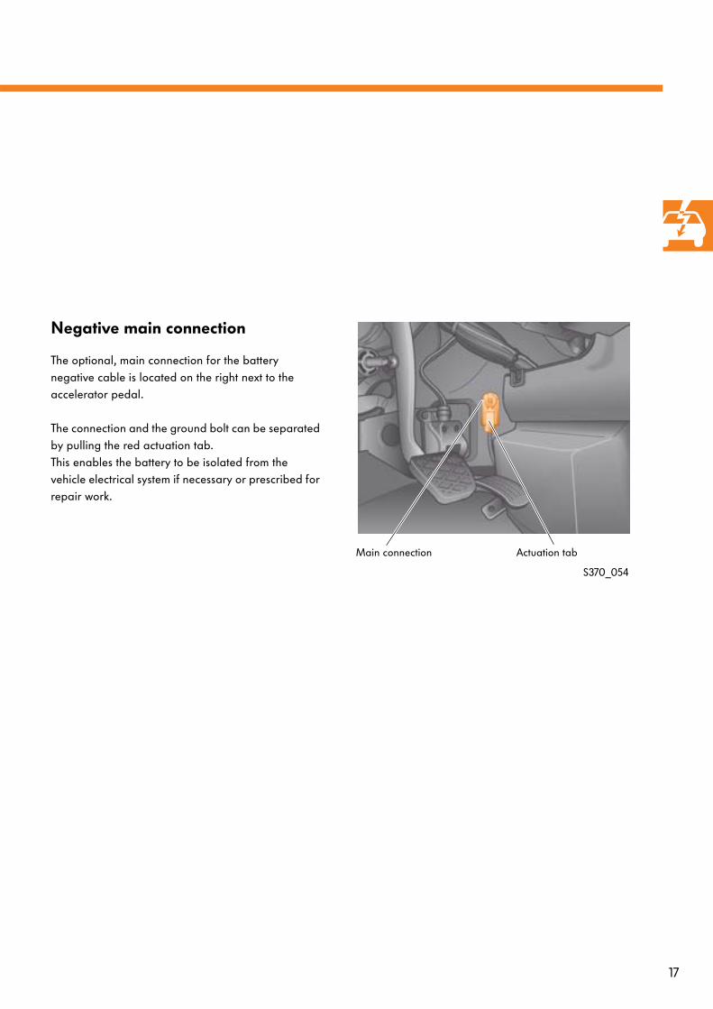
Negative main connection
The optional, main connection for the battery negative cable is located on the right next to the accelerator pedal.
The connection and the ground bolt can be separated by pulling the red actuation tab.This enables the battery to be isolated from the vehicle electrical system if necessary or prescribed for repair work.
S370_054
Main connection Actuation tab
18
Vehicle electrical system
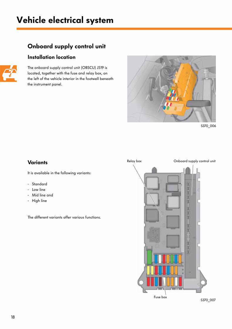
Onboard supply control unit
Installation location
The onboard supply control unit (OBSCU) J519 is located, together with the fuse and relay box, on the left of the vehicle interior in the footwell beneath the instrument panel.
Variants
It is available in the following variants:
- Standard- Low line- Mid line and- High line
The different variants offer various functions.
S370_006
S370_007
Relay box Onboard supply control unit
Fuse box
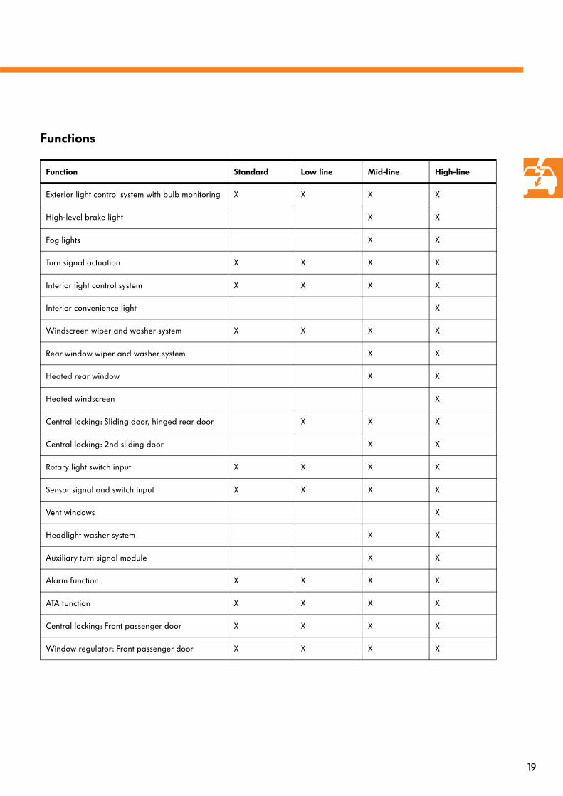
19
Functions
Function Standard Low line Mid-line High-line
Exterior light control system with bulb monitoring X X X X
High-level brake light X X
Fog lights X X
Turn signal actuation X X X X
Interior light control system X X X X
Interior convenience light X
Windscreen wiper and washer system X X X X
Rear window wiper and washer system X X
Heated rear window X X
Heated windscreen X
Central locking: Sliding door, hinged rear door X X X
Central locking: 2nd sliding door X X
Rotary light switch input X X X X
Sensor signal and switch input X X X X
Vent windows X
Headlight washer system X X
Auxiliary turn signal module X X
Alarm function X X X X
ATA function X X X X
Central locking: Front passenger door X X X X
Window regulator: Front passenger door X X X X
20
Vehicle electrical system
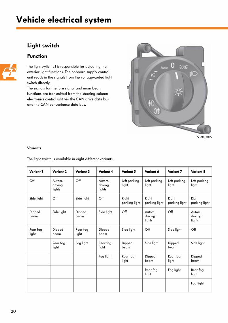
Light switch
Function
The light switch E1 is responsible for actuating the exterior light functions. The onboard supply control unit reads in the signals from the voltage-coded light switch directly. The signals for the turn signal and main beam functions are transmitted from the steering column electronics control unit via the CAN drive data bus and the CAN convenience data bus.
Variants
The light swicth is available in eight different variants.
Variant 1 Variant 2 Variant 3 Variant 4 Variant 5 Variant 6 Variant 7 Variant 8
Off Autom. driving lights
Off Autom. driving lights
Left parking light
Left parking light
Left parking light
Left parking light
Side light Off Side light Off Right parking light
Right parking light
Right parking light
Right parking light
Dipped beam
Side light Dipped beam
Side light Off Autom. driving lights
Off Autom. driving lights
Rear fog light
Dipped beam
Rear fog light
Dipped beam
Side light Off Side light Off
Rear fog light
Fog light Rear fog light
Dipped beam
Side light Dipped beam
Side light
Fog light Rear fog light
Dipped beam
Rear fog light
Dipped beam
Rear fog light
Fog light Rear fog light
Fog light
S370_005
21
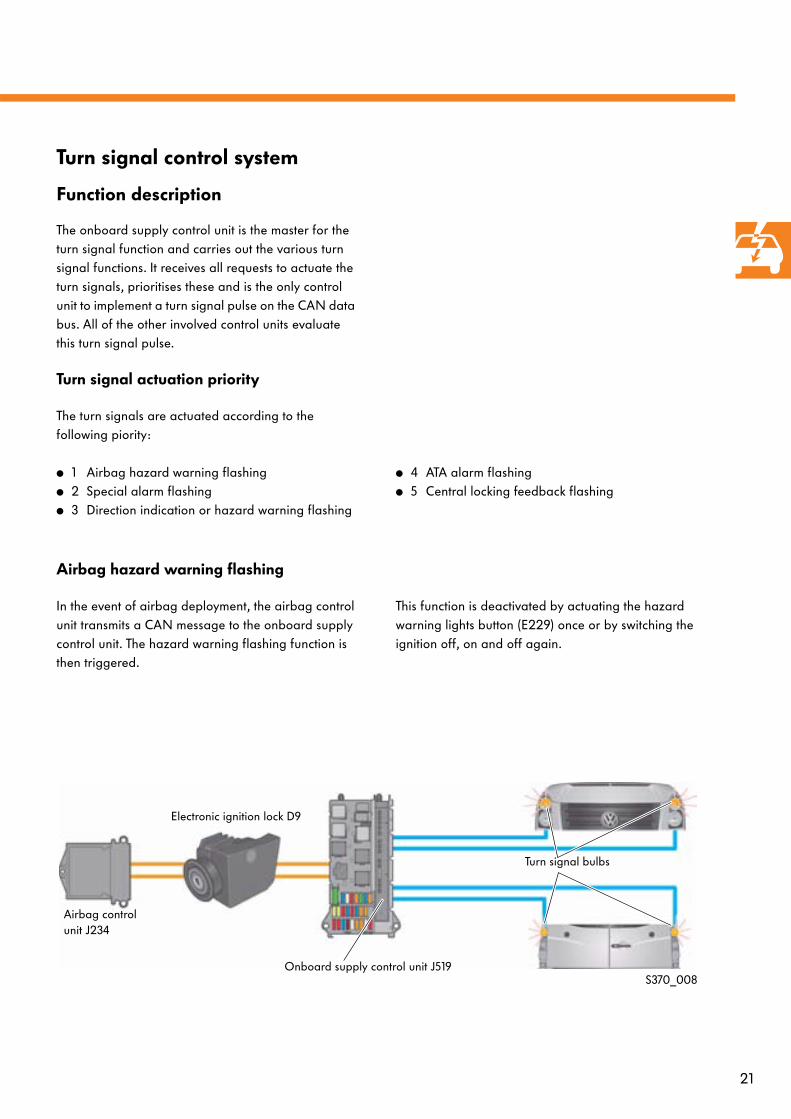
Turn signal control system
Function description
The onboard supply control unit is the master for the turn signal function and carries out the various turn signal functions. It receives all requests to actuate the turn signals, prioritises these and is the only control unit to implement a turn signal pulse on the CAN data bus. All of the other involved control units evaluate this turn signal pulse.
Turn signal actuation priority
The turn signals are actuated according to the following piority:
● 1 Airbag hazard warning flashing● 2 Special alarm flashing● 3 Direction indication or hazard warning flashing
● 4 ATA alarm flashing● 5 Central locking feedback flashing
Airbag hazard warning flashing
In the event of airbag deployment, the airbag control unit transmits a CAN message to the onboard supply control unit. The hazard warning flashing function is then triggered.
This function is deactivated by actuating the hazard warning lights button (E229) once or by switching the ignition off, on and off again.
S370_008
Airbag control unit J234
Electronic ignition lock D9
Onboard supply control unit J519
Turn signal bulbs
22
Vehicle electrical system
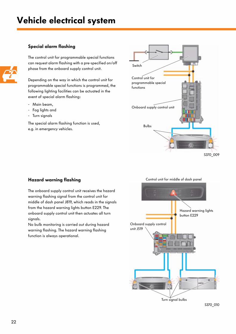
Special alarm flashing
The control unit for programmable special functions can request alarm flashing with a pre-specified on/off phase from the onboard supply control unit.
Depending on the way in which the control unit for programmable special functions is programmed, the following lighting facilities can be actuated in the event of special alarm flashing:
- Main beam,- Fog lights and - Turn signals
The special alarm flashing function is used, e.g. in emergency vehicles.
Hazard warning flashing
The onboard supply control unit receives the hazard warning flashing signal from the control unit for middle of dash panel J819, which reads in the signals from the hazard warning lights button E229. The onboard supply control unit then actuates all turn signals. No bulb monitoring is carried out during hazard warning flashing. The hazard warning flashing function is always operational.
S370_009
S370_010
Hazard warning lights button E229
Turn signal bulbs
Onboard supply control unit J519
Switch
Control unit for programmable special functions
Onboard supply control unit
Bulbs
Control unit for middle of dash panel
23
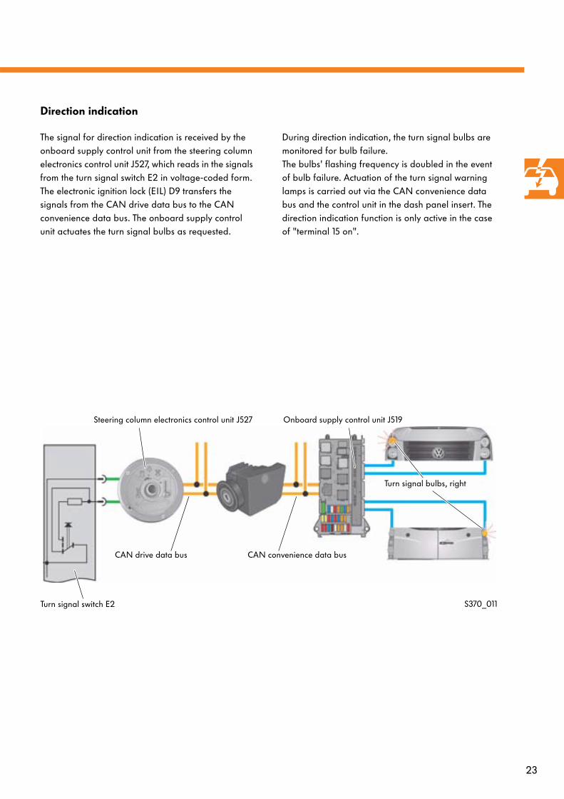
Direction indication
The signal for direction indication is received by the onboard supply control unit from the steering column electronics control unit J527, which reads in the signals from the turn signal switch E2 in voltage-coded form. The electronic ignition lock (EIL) D9 transfers the signals from the CAN drive data bus to the CAN convenience data bus. The onboard supply control unit actuates the turn signal bulbs as requested.
During direction indication, the turn signal bulbs are monitored for bulb failure. The bulbs' flashing frequency is doubled in the event of bulb failure. Actuation of the turn signal warning lamps is carried out via the CAN convenience data bus and the control unit in the dash panel insert. The direction indication function is only active in the case of "terminal 15 on".
S370_011Turn signal switch E2
Steering column electronics control unit J527
CAN drive data bus CAN convenience data bus
Onboard supply control unit J519
Turn signal bulbs, right
24
Vehicle electrical system
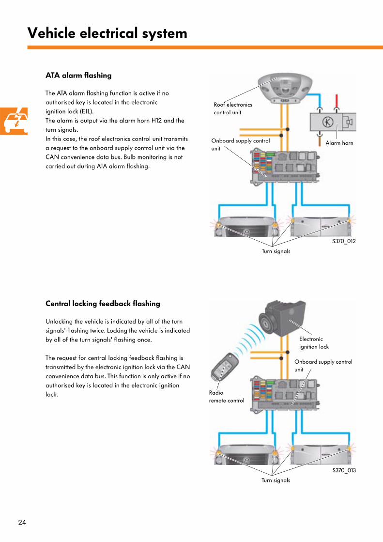
ATA alarm flashing
The ATA alarm flashing function is active if no authorised key is located in the electronic ignition lock (EIL). The alarm is output via the alarm horn H12 and the turn signals. In this case, the roof electronics control unit transmits a request to the onboard supply control unit via the CAN convenience data bus. Bulb monitoring is not carried out during ATA alarm flashing.
Central locking feedback flashing
Unlocking the vehicle is indicated by all of the turn signals' flashing twice. Locking the vehicle is indicated by all of the turn signals' flashing once.
The request for central locking feedback flashing is transmitted by the electronic ignition lock via the CAN convenience data bus. This function is only active if no authorised key is located in the electronic ignition lock.
S370_012
S370_013
Roof electronicscontrol unit
Onboard supply control unit
Alarm horn
Turn signals
Electronicignition lock
Turn signals
Onboard supply control unit
Radio remote control
25
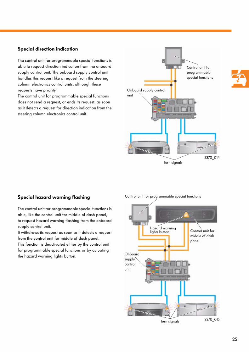
Special direction indication
The control unit for programmable special functions is able to request direction indication from the onboard supply control unit. The onboard supply control unit handles this request like a request from the steering column electronics control units, although these requests have priority.The control unit for programmable special functions does not send a request, or ends its request, as soon as it detects a request for direction indication from the steering column electronics control unit.
Special hazard warning flashing
The control unit for programmable special functions is able, like the control unit for middle of dash panel, to request hazard warning flashing from the onboard supply control unit. It withdraws its request as soon as it detects a request from the control unit for middle of dash panel.This function is deactivated either by the control unit for programmable special functions or by actuating the hazard warning lights button.
S370_014
S370_015
Control unit for programmable special functions
Onboard supply control unit
Turn signals
Control unit for programmable special functions
Control unit for middle of dash panel
Onboard supply control unit
Turn signals
Hazard warning lights button
26
Vehicle electrical system
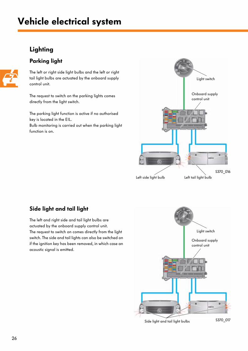
Lighting
Parking light
The left or right side light bulbs and the left or right tail light bulbs are actuated by the onboard supply control unit.
The request to switch on the parking lights comes directly from the light switch.
The parking light function is active if no authorised key is located in the EIL.Bulb monitoring is carried out when the parking light function is on.
Side light and tail light
The left and right side and tail light bulbs are actuated by the onboard supply control unit. The request to switch on comes directly from the light switch. The side and tail lights can also be switched on if the ignition key has been removed, in which case an acoustic signal is emitted.
S370_016
S370_017
Light switch
Onboard supply control unit
Left side light bulb Left tail light bulb
Light switch
Onboard supply control unit
Side light and tail light bulbs
27
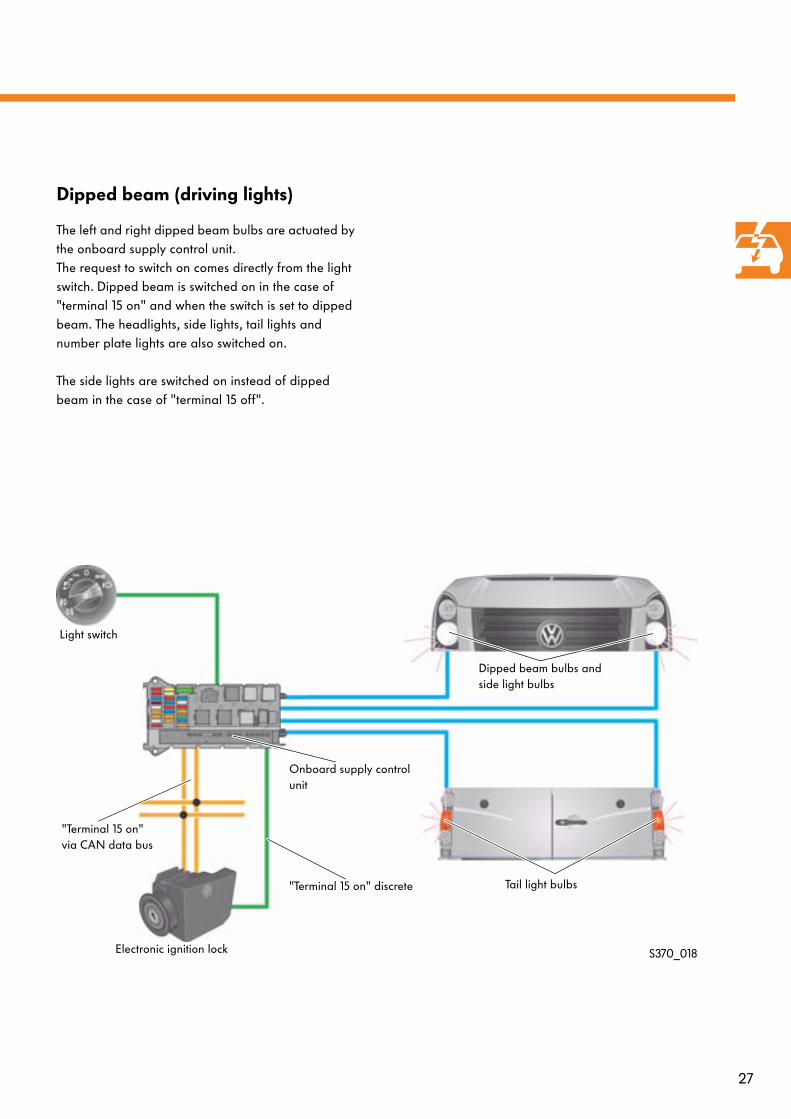
Dipped beam (driving lights)
The left and right dipped beam bulbs are actuated by the onboard supply control unit. The request to switch on comes directly from the light switch. Dipped beam is switched on in the case of "terminal 15 on" and when the switch is set to dipped beam. The headlights, side lights, tail lights and number plate lights are also switched on.
The side lights are switched on instead of dipped beam in the case of "terminal 15 off".
S370_018
Light switch
Onboard supply control unit
Electronic ignition lock
"Terminal 15 on" discrete
"Terminal 15 on" via CAN data bus
Dipped beam bulbs and side light bulbs
Tail light bulbs
28
Vehicle electrical system
S370_019
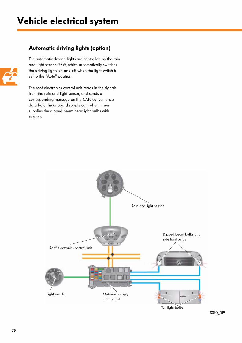
Automatic driving lights (option)
The automatic driving lights are controlled by the rain and light sensor G397, which automatically switches the driving lights on and off when the light switch is set to the "Auto" position.
The roof electronics control unit reads in the signals from the rain and light sensor, and sends a corresponding message on the CAN convenience data bus. The onboard supply control unit then supplies the dipped beam headlight bulbs with current.
Rain and light sensor
Roof electronics control unit
Light switch Onboard supply control unit
Dipped beam bulbs and side light bulbs
Tail light bulbs
29
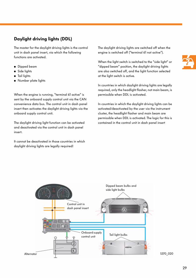
Daylight driving lights (DDL)
The master for the daylight driving lights is the control unit in dash panel insert, via which the following functions are activated.
● Dipped beam● Side lights● Tail lights● Number plate lights
When the engine is running, "terminal 61 active" is sent by the onboard supply control unit via the CAN convenience data bus. The control unit in dash panel insert then activates the daylight driving lights via the onboard supply control unit.
The daylight driving light function can be activated and deactivated via the control unit in dash panel insert.
It cannot be deactivated in those countries in which daylight driving lights are legally required!
The daylight driving lights are switched off when the engine is switched off ("terminal 61 not active").
When the light switch is switched to the "side light" or "dipped beam" position, the daylight driving lights are also switched off, and the light function selected at the light switch is active.
In countries in which daylight driving lights are legally required, only the headlight flasher, not main beam, is permissible when DDL is activated.
In countries in which the daylight driving lights can be activated/deactivated by the user via the instrument cluster, the headlight flasher and main beam are permissible when DDL is activated. The logic for this is contained in the control unit in dash panel insert
S370_020
Tail light bulbs
Dipped beam bulbs and side light bulbs
Onboard supply control unit
Alternator
Control unit indash panel insert
30
Vehicle electrical system
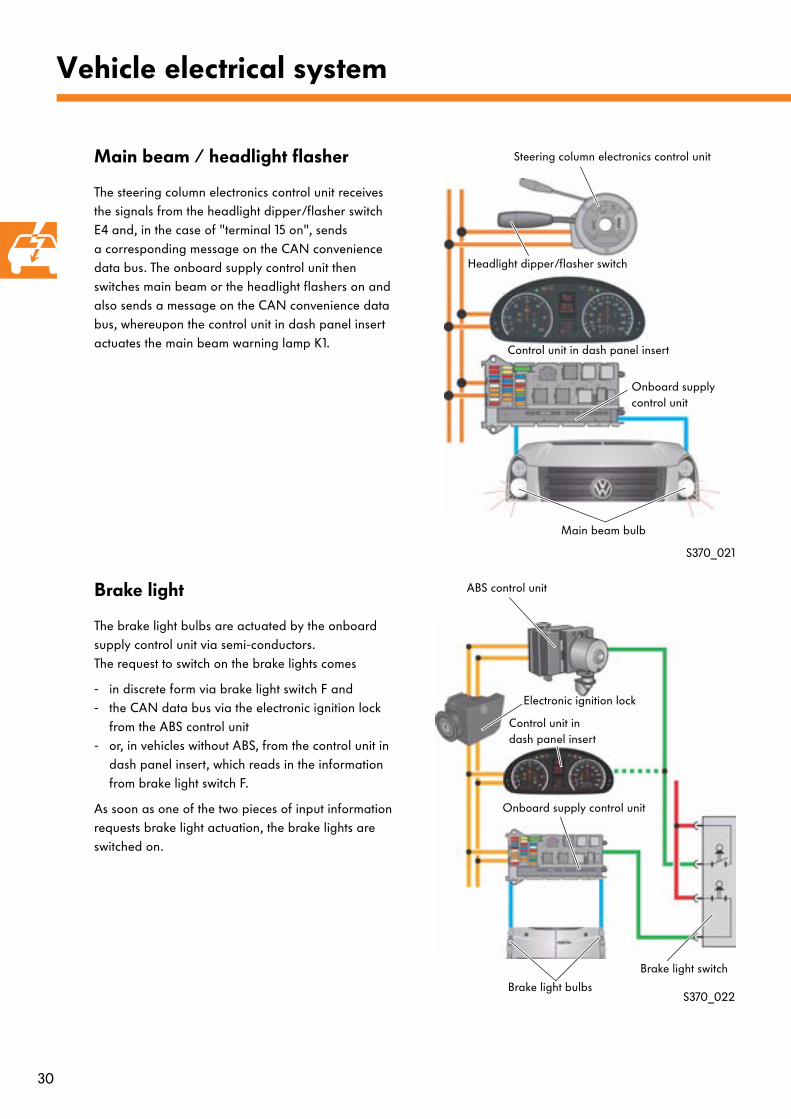
Main beam / headlight flasher
The steering column electronics control unit receives the signals from the headlight dipper/flasher switch E4 and, in the case of "terminal 15 on", sends a corresponding message on the CAN convenience data bus. The onboard supply control unit then switches main beam or the headlight flashers on and also sends a message on the CAN convenience data bus, whereupon the control unit in dash panel insert actuates the main beam warning lamp K1.
Brake light
The brake light bulbs are actuated by the onboard supply control unit via semi-conductors. The request to switch on the brake lights comes
- in discrete form via brake light switch F and- the CAN data bus via the electronic ignition lock
from the ABS control unit- or, in vehicles without ABS, from the control unit in
dash panel insert, which reads in the information from brake light switch F.
As soon as one of the two pieces of input information requests brake light actuation, the brake lights are switched on.
S370_021
S370_022
Steering column electronics control unit
Headlight dipper/flasher switch
Control unit in dash panel insert
Onboard supply control unit
Main beam bulb
ABS control unit
Electronic ignition lock
Control unit indash panel insert
Onboard supply control unit
Brake light switch
Brake light bulbs
31
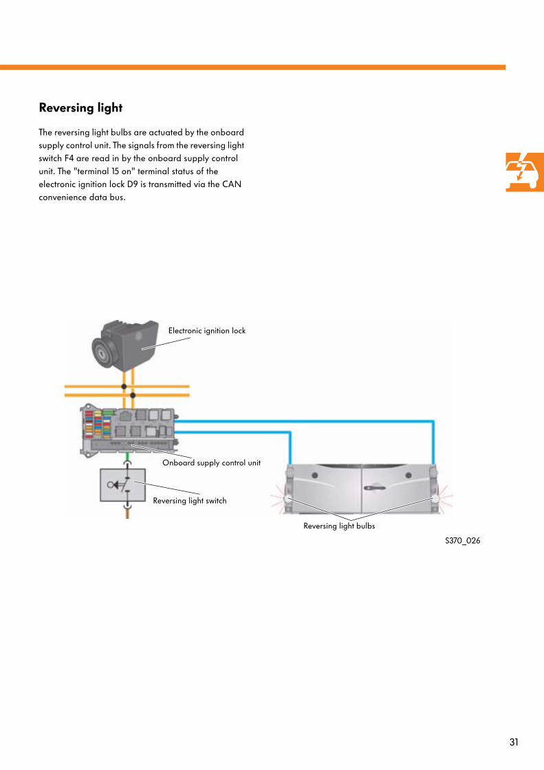
Reversing light
The reversing light bulbs are actuated by the onboard supply control unit. The signals from the reversing light switch F4 are read in by the onboard supply control unit. The "terminal 15 on" terminal status of the electronic ignition lock D9 is transmitted via the CAN convenience data bus.
S370_026
Electronic ignition lock
Onboard supply control unit
Reversing light switch
Reversing light bulbs
32
Vehicle electrical system
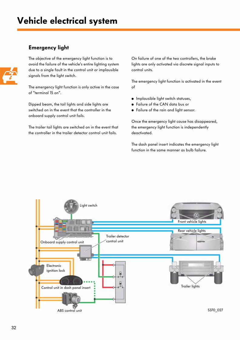
Emergency light
The objective of the emergency light function is to avoid the failure of the vehicle's entire lighting system due to a single fault in the control unit or implausible signals from the light switch.
The emergency light function is only active in the case of "terminal 15 on".
Dipped beam, the tail lights and side lights are switched on in the event that the controller in the onboard supply control unit fails.
The trailer tail lights are switched on in the event that the controller in the trailer detector control unit fails.
On failure of one of the two controllers, the brake lights are only activated via discrete signal inputs to control units.
The emergency light function is activated in the event of
● Implausible light switch statuses,● Failure of the CAN data bus or ● Failure of the rain and light sensor.
Once the emergency light cause has disappeared, the emergency light function is independently deactivated.
The dash panel insert indicates the emergency light function in the same manner as bulb failure.
S370_027
Light switch
Onboard supply control unit
Front vehicle lights
Rear vehicle lights
Trailer lights
Trailer detector control unit
Control unit in dash panel insert
ABS control unit
Electronic ignition lock
33
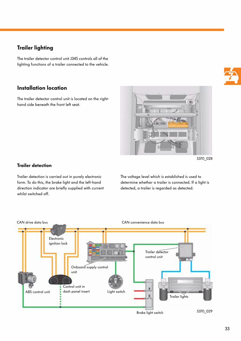
Trailer lighting
The trailer detector control unit J345 controls all of the lighting functions of a trailer connected to the vehicle.
Installation location
The trailer detector control unit is located on the right-hand side beneath the front left seat.
S370_028
Trailer detection
Trailer detection is carried out in purely electronic form. To do this, the brake light and the left-hand direction indicator are briefly supplied with current whilst switched off.
The voltage level which is established is used to determine whether a trailer is connected. If a light is detected, a trailer is regarded as detected.
S370_029
Trailer detector control unit
Light switch
Brake light switch
ABS control unit
Control unit in dash panel insert
Onboard supply control unit
Trailer lights
Electronic ignition lock
CAN convenience data busCAN drive data bus
34
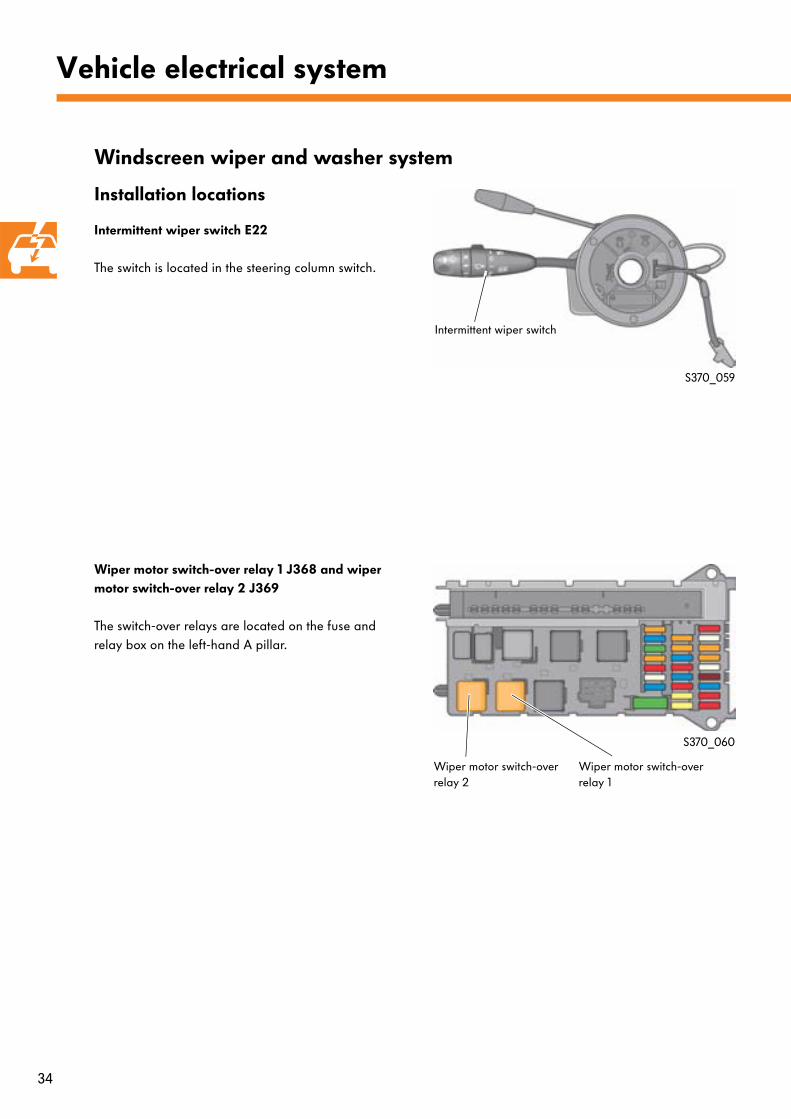
Installation locations
Intermittent wiper switch E22
The switch is located in the steering column switch.
Wiper motor switch-over relay 1 J368 and wiper motor switch-over relay 2 J369
The switch-over relays are located on the fuse and relay box on the left-hand A pillar.
Windscreen wiper and washer system
Vehicle electrical system
S370_059
S370_060
Intermittent wiper switch
Wiper motor switch-over relay 2
Wiper motor switch-over relay 1
35
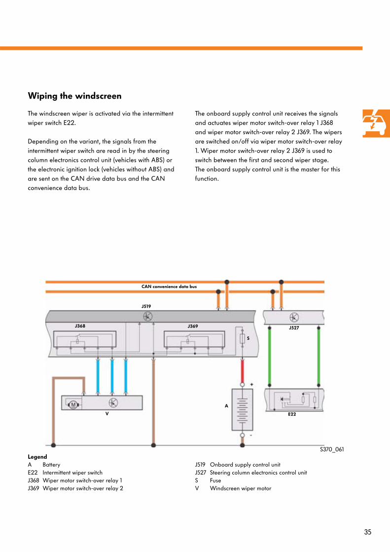
Wiping the windscreen
The windscreen wiper is activated via the intermittent wiper switch E22.
Depending on the variant, the signals from the intermittent wiper switch are read in by the steering column electronics control unit (vehicles with ABS) or the electronic ignition lock (vehicles without ABS) and are sent on the CAN drive data bus and the CAN convenience data bus.
The onboard supply control unit receives the signals and actuates wiper motor switch-over relay 1 J368 and wiper motor switch-over relay 2 J369. The wipers are switched on/off via wiper motor switch-over relay 1. Wiper motor switch-over relay 2 J369 is used to switch between the first and second wiper stage.The onboard supply control unit is the master for this function.
LegendA BatteryE22 Intermittent wiper switchJ368 Wiper motor switch-over relay 1J369 Wiper motor switch-over relay 2
J519 Onboard supply control unitJ527 Steering column electronics control unitS FuseV Windscreen wiper motor
V
J519
A
J527
E22
J368 J369
CAN convenience data bus
S
S370_061
36
Vehicle electrical system
Rain and light sensor
Functional prerequisite
Communication between the onboard supply control unit and the roof electronics control unit only takes place if the "rain/light sensor" option has been adapted as present in the variant coding in the EIL.
If the rain and light sensor G397 is installed and the intermittent function is active, wiping is requested by the sensor. It is connected to the roof electronics control unit. Data communication between the roof electronics control unit and the onboard supply control unit takes place via the CAN convenience data bus.
The rain and light sensor can be used to control the interval times from "wipers off" to "continuous wiping in stage 1 or 2".
During rain sensor operation, the roof electronics control unit acts as the master and the onboard supply control unit as the slave. This means that wiper control is carried out entirely by the roof electronics control unit; the onboard supply control unit only actuates wiper motor switch-over relay 1 J368 and wiper motor switch-over relay 2 J369 when requested to do so by the roof electronics control unit J528. The "touch-wiping" and "washing" switch positions are the exceptions.
If this is not the case, the onboard supply control unit controls the "intermittent wiping" function as in vehicles without a rain and light sensor.
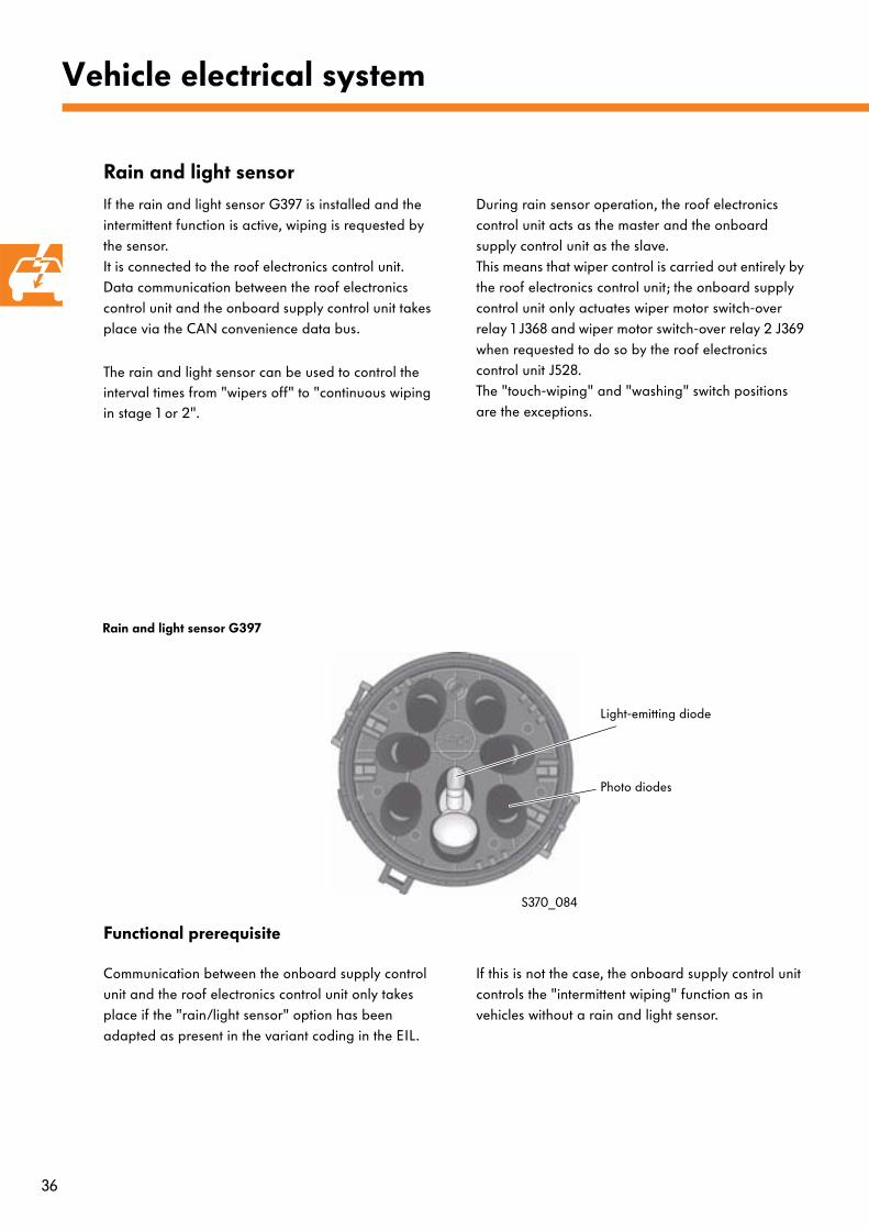
Rain and light sensor G397
S370_084
Light-emitting diode
Photo diodes
37
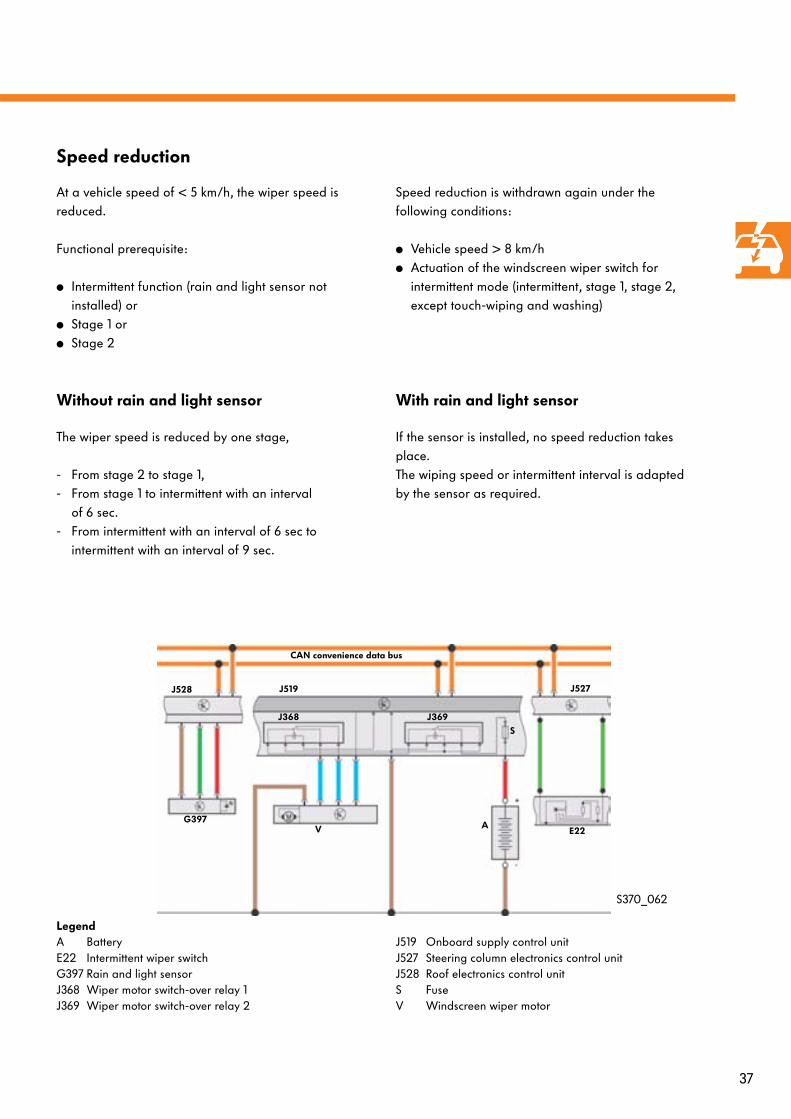
LegendA BatteryE22 Intermittent wiper switchG397 Rain and light sensorJ368 Wiper motor switch-over relay 1J369 Wiper motor switch-over relay 2
J519 Onboard supply control unitJ527 Steering column electronics control unitJ528 Roof electronics control unitS FuseV Windscreen wiper motor
Speed reduction
At a vehicle speed of < 5 km/h, the wiper speed is reduced.
Functional prerequisite:
● Intermittent function (rain and light sensor not installed) or
● Stage 1 or● Stage 2
Speed reduction is withdrawn again under the following conditions:
● Vehicle speed > 8 km/h● Actuation of the windscreen wiper switch for
intermittent mode (intermittent, stage 1, stage 2, except touch-wiping and washing)
Without rain and light sensor
The wiper speed is reduced by one stage,
- From stage 2 to stage 1,- From stage 1 to intermittent with an interval
of 6 sec.- From intermittent with an interval of 6 sec to
intermittent with an interval of 9 sec.
With rain and light sensor
If the sensor is installed, no speed reduction takes place. The wiping speed or intermittent interval is adapted by the sensor as required.
S370_062
J528
G397V
J519
A
J527
E22
J368 J369
CAN convenience data bus
S
38
Vehicle electrical system
Rear window wiper
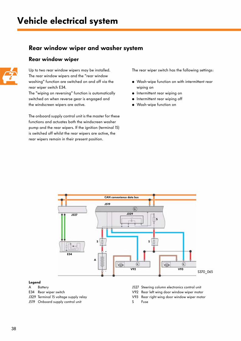
Up to two rear window wipers may be installed. The rear window wipers and the "rear window washing" function are switched on and off via the rear wiper switch E34. The "wiping on reversing" function is automatically switched on when reverse gear is engaged and the windscreen wipers are active.
The onboard supply control unit is the master for these functions and actuates both the windscreen washer pump and the rear wipers. If the ignition (terminal 15) is switched off whilst the rear wipers are active, the rear wipers remain in their present position.
The rear wiper switch has the following settings:
● Wash-wipe function on with intermittent rear wiping on
● Intermittent rear wiping on● Intermittent rear wiping off● Wash-wipe function on
Rear window wiper and washer system
S370_065
LegendA BatteryE34 Rear wiper switchJ329 Terminal 15 voltage supply relayJ519 Onboard supply control unit
J527 Steering column electronics control unitV92 Rear left wing door window wiper motorV93 Rear right wing door window wiper motorS Fuse
E34
J527
V92 V93
J329
A
J519
S S
S
CAN convenience data bus
39
Functions
Rear wiping with windscreen wipers switched off
When the windscreen wipers are switched off, the rear window wiping function is carried out in intermittent mode with the standard interval time of 6 seconds.
Rear window wiping with windscreen wipers set to "intermittent"
When intermittent windscreen wiping is switched on, the rear window wiping function is dependent on the presence of a rain and light sensor.
● Without sensor: Rear wiping is synchronised with windscreen wiping
● With sensor: Rear wiping is carried out with the standard interval time of 6 sec.
Windscreen wipers set to stage 1 or 2
If the windscreen wiper switch for intermittent mode is set to stage 1 or 2, rear wiper actuation is always synchronised with the windscreen wipers, in which case the rear wipers only wipe for a defined percentage of the windscreen wiper cycle. This percentage is speed-dependent.
● v < 80 km/h: Rear wipers wipe for 1/10 of the windscreen wiper cycle.
● v > 80 km/h: Rear wipers wipe for 1/7 of the windscreen wiper cycle.
Rear door open
The wash-wipe function is interrupted when the vehicle is stationary and the rear door is open, and is continued when the rear door is closed.
40
Vehicle electrical system
Heated windscreen
Function
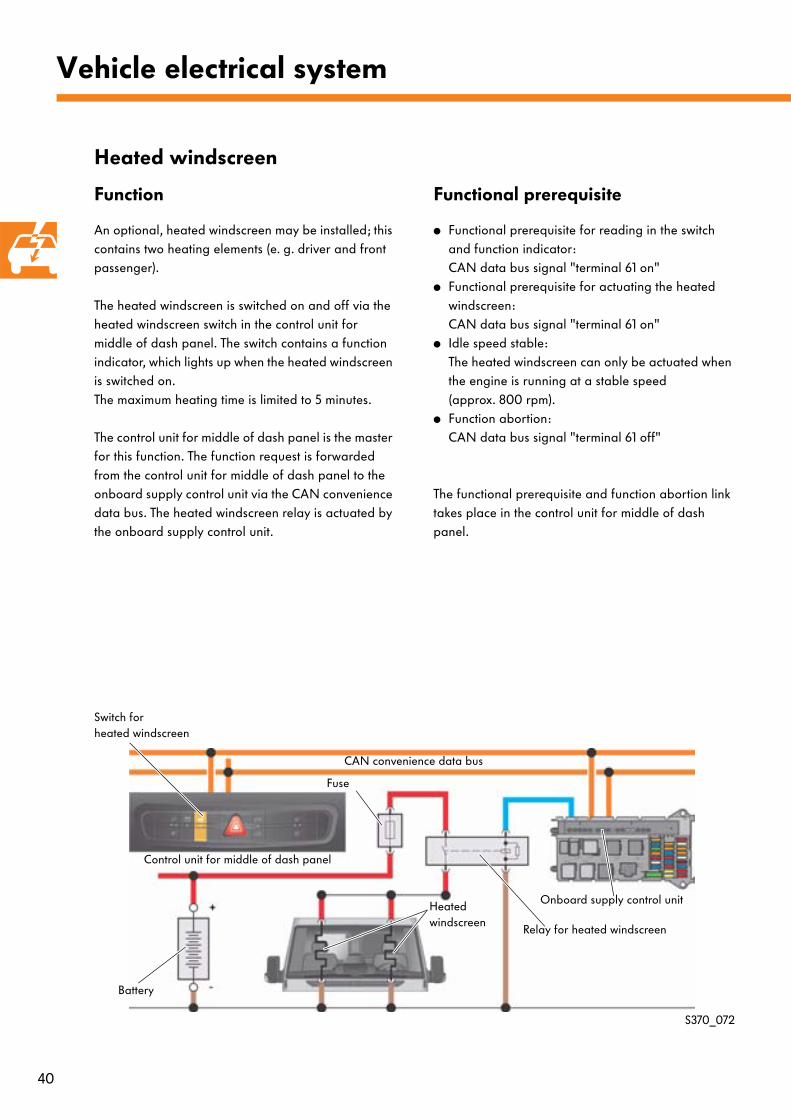
An optional, heated windscreen may be installed; this contains two heating elements (e. g. driver and front passenger).
The heated windscreen is switched on and off via the heated windscreen switch in the control unit for middle of dash panel. The switch contains a function indicator, which lights up when the heated windscreen is switched on. The maximum heating time is limited to 5 minutes.
The control unit for middle of dash panel is the master for this function. The function request is forwarded from the control unit for middle of dash panel to the onboard supply control unit via the CAN convenience data bus. The heated windscreen relay is actuated by the onboard supply control unit.
Functional prerequisite
● Functional prerequisite for reading in the switch and function indicator:CAN data bus signal "terminal 61 on"
● Functional prerequisite for actuating the heated windscreen:CAN data bus signal "terminal 61 on"
● Idle speed stable:The heated windscreen can only be actuated when the engine is running at a stable speed (approx. 800 rpm).
● Function abortion:CAN data bus signal "terminal 61 off"
The functional prerequisite and function abortion link takes place in the control unit for middle of dash panel.
S370_072
Switch forheated windscreen
Control unit for middle of dash panel
Battery
Fuse
Relay for heated windscreen
Onboard supply control unitHeated windscreen
CAN convenience data bus
41
Heated rear window
Function
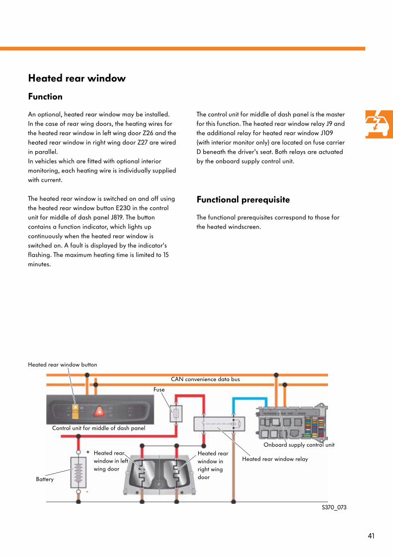
An optional, heated rear window may be installed. In the case of rear wing doors, the heating wires for the heated rear window in left wing door Z26 and the heated rear window in right wing door Z27 are wired in parallel. In vehicles which are fitted with optional interior monitoring, each heating wire is individually supplied with current.
The heated rear window is switched on and off using the heated rear window button E230 in the control unit for middle of dash panel J819. The button contains a function indicator, which lights up continuously when the heated rear window is switched on. A fault is displayed by the indicator's flashing. The maximum heating time is limited to 15 minutes.
The control unit for middle of dash panel is the master for this function. The heated rear window relay J9 and the additional relay for heated rear window J109 (with interior monitor only) are located on fuse carrier D beneath the driver's seat. Both relays are actuated by the onboard supply control unit.
Functional prerequisite
The functional prerequisites correspond to those for the heated windscreen.
S370_073
Heated rear window button
Control unit for middle of dash panel
Onboard supply control unit
Battery
Fuse
Heated rear window relayHeated rear window in left wing door
Heated rear window in right wing door
CAN convenience data bus
42
Vehicle electrical system
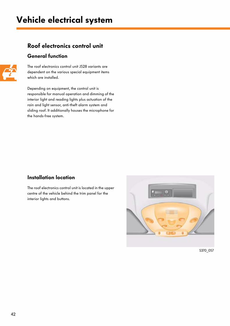
Installation location
The roof electronics control unit is located in the upper centre of the vehicle behind the trim panel for the interior lights and buttons.
Roof electronics control unit
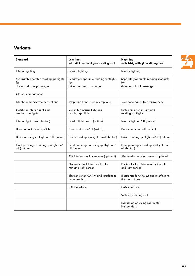
General function
The roof electronics control unit J528 variants are dependent on the various special equipment items which are installed.
Depending on equipment, the control unit is responsible for manual operation and dimming of the interior light and reading lights plus actuation of the rain and light sensor, anti-theft alarm system and sliding roof. It additionally houses the microphone for the hands-free system.
S370_057
43
Variants
Standard Low linewith ATA, without glass sliding roof
High-linewith ATA, with glass sliding roof
Interior lighting Interior lighting Interior lighting
Separately operable reading spotlights for driver and front passenger
Separately operable reading spotlights for driver and front passenger
Separately operable reading spotlights for driver and front passenger
Glasses compartment
Telephone hands-free microphone Telephone hands-free microphone Telephone hands-free microphone
Switch for interior light and reading spotlights
Switch for interior light and reading spotlights
Switch for interior light and reading spotlights
Interior light on/off (button) Interior light on/off (button) Interior light on/off (button)
Door contact on/off (switch) Door contact on/off (switch) Door contact on/off (switch)
Driver reading spotlight on/off (button) Driver reading spotlight on/off (button) Driver reading spotlight on/off (button)
Front passenger reading spotlight on/off (button)
Front passenger reading spotlight on/off (button)
Front passenger reading spotlight on/off (button)
ATA interior monitor sensors (optional) ATA interior monitor sensors (optional)
Electronics incl. interface for the rain and light sensor
Electronics incl. interface for the rain and light sensor
Electronics for ATA/IM and interface to the alarm horn
Electronics for ATA/IM and interface to the alarm horn
CAN interface CAN interface
Switch for sliding roof
Evaluation of sliding roof motor Hall senders
44
Vehicle electrical system
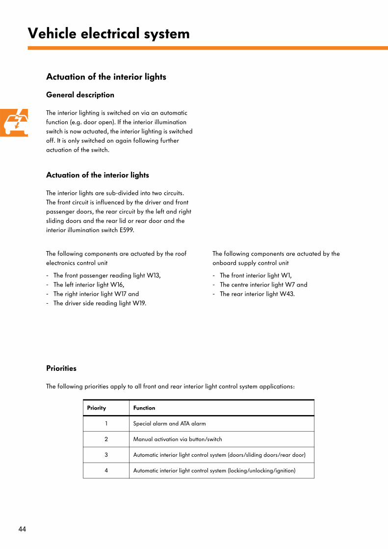
Actuation of the interior lights
General description
The interior lighting is switched on via an automatic function (e.g. door open). If the interior illumination switch is now actuated, the interior lighting is switched off. It is only switched on again following further actuation of the switch.
Actuation of the interior lights
The interior lights are sub-divided into two circuits. The front circuit is influenced by the driver and front passenger doors, the rear circuit by the left and right sliding doors and the rear lid or rear door and the interior illumination switch E599.
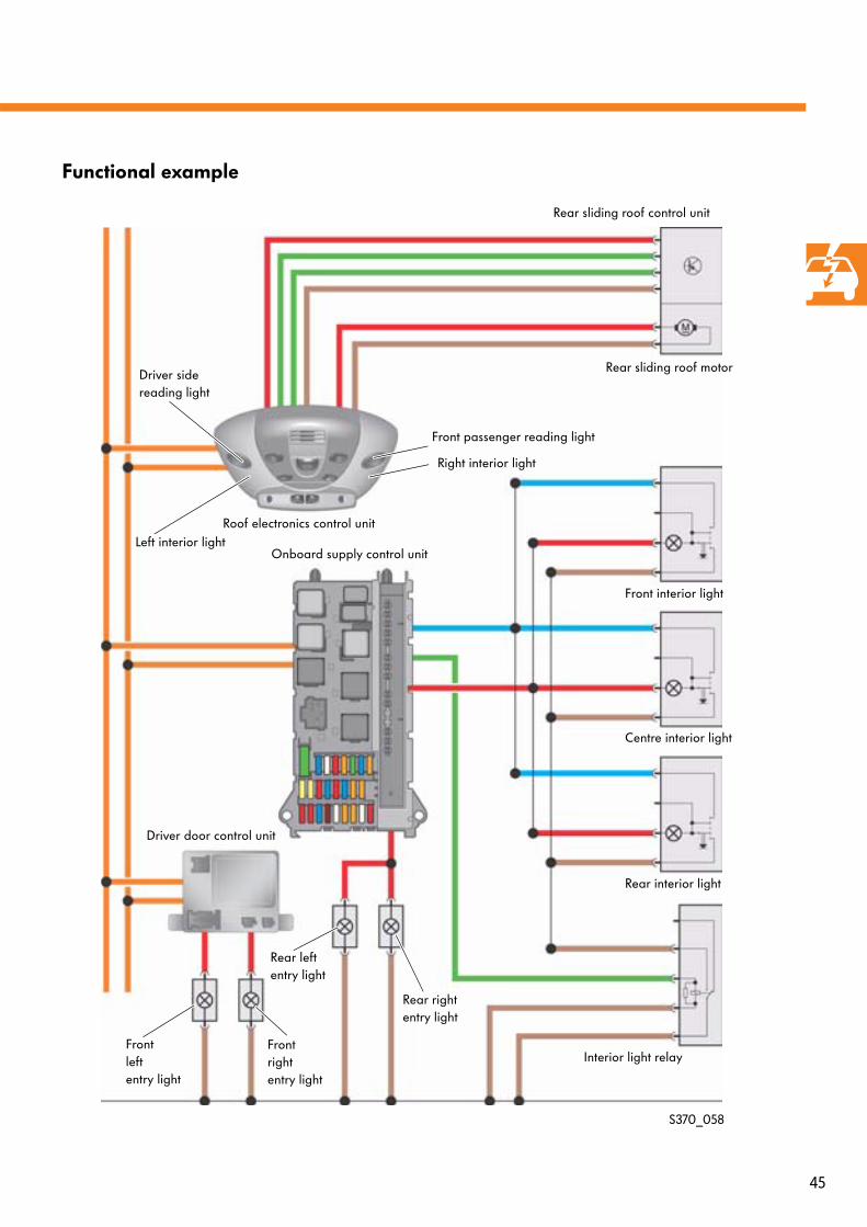
The following components are actuated by the roof electronics control unit
- The front passenger reading light W13,- The left interior light W16,- The right interior light W17 and - The driver side reading light W19.
The following components are actuated by the onboard supply control unit
- The front interior light W1,- The centre interior light W7 and - The rear interior light W43.
Priorities
The following priorities apply to all front and rear interior light control system applications:
Priority Function
1 Special alarm and ATA alarm
2 Manual activation via button/switch
3 Automatic interior light control system (doors/sliding doors/rear door)
4 Automatic interior light control system (locking/unlocking/ignition)
45
Functional example
S370_058
Roof electronics control unit
Onboard supply control unit
Driver door control unit
Front interior light
Centre interior light
Rear interior light
Interior light relayFront left entry light
Front right entry light
Rear sliding roof control unit
Rear sliding roof motor
Rear left entry light
Rear right entry light
Front passenger reading light
Driver sidereading light
Right interior light
Left interior light
46
Ignition lock
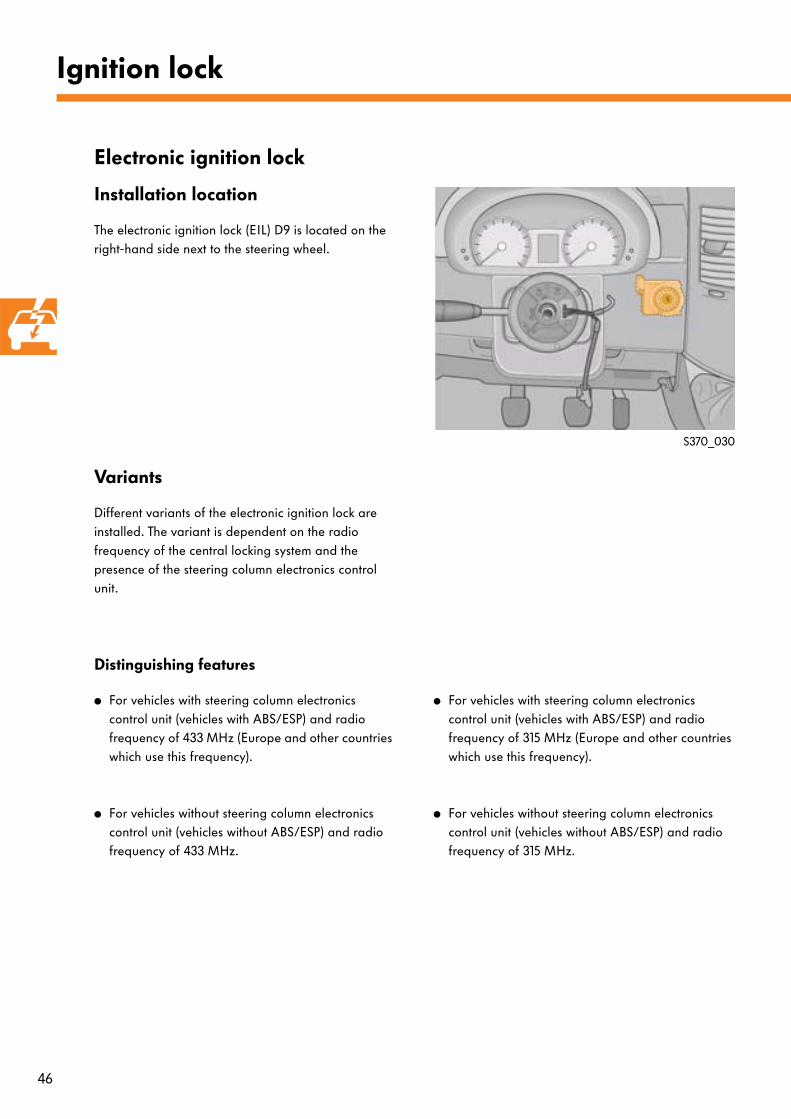
Electronic ignition lock
Installation location
The electronic ignition lock (EIL) D9 is located on the right-hand side next to the steering wheel.
Variants
Different variants of the electronic ignition lock are installed. The variant is dependent on the radio frequency of the central locking system and the presence of the steering column electronics control unit.
Distinguishing features
● For vehicles with steering column electronics control unit (vehicles with ABS/ESP) and radio frequency of 433 MHz (Europe and other countries which use this frequency).
● For vehicles without steering column electronics control unit (vehicles without ABS/ESP) and radio frequency of 433 MHz.
● For vehicles with steering column electronics control unit (vehicles with ABS/ESP) and radio frequency of 315 MHz (Europe and other countries which use this frequency).
● For vehicles without steering column electronics control unit (vehicles without ABS/ESP) and radio frequency of 315 MHz.
S370_030
47
Starting
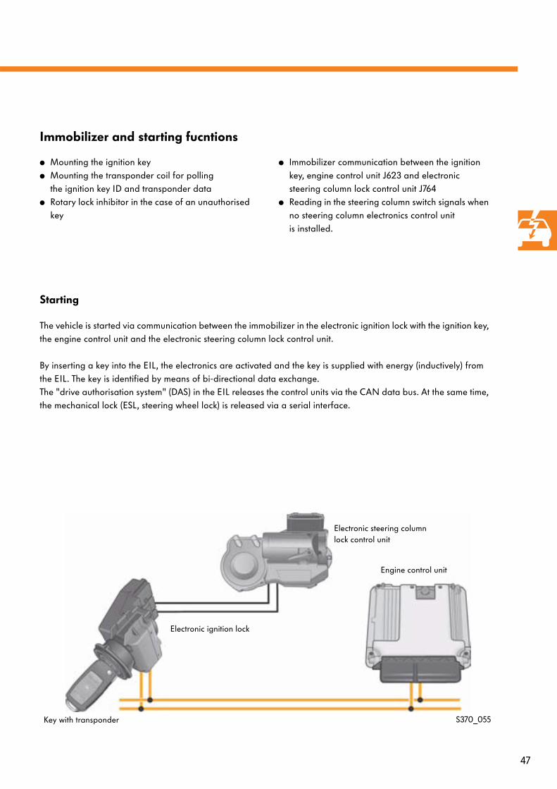
The vehicle is started via communication between the immobilizer in the electronic ignition lock with the ignition key, the engine control unit and the electronic steering column lock control unit.
By inserting a key into the EIL, the electronics are activated and the key is supplied with energy (inductively) from the EIL. The key is identified by means of bi-directional data exchange. The "drive authorisation system" (DAS) in the EIL releases the control units via the CAN data bus. At the same time, the mechanical lock (ESL, steering wheel lock) is released via a serial interface.
Immobilizer and starting fucntions
S370_055
● Mounting the ignition key● Mounting the transponder coil for polling
the ignition key ID and transponder data● Rotary lock inhibitor in the case of an unauthorised
key
● Immobilizer communication between the ignition key, engine control unit J623 and electronic steering column lock control unit J764
● Reading in the steering column switch signals when no steering column electronics control unit is installed.
Key with transponder
Electronic ignition lock
Engine control unit
Electronic steering column lock control unit
48
Ignition lock
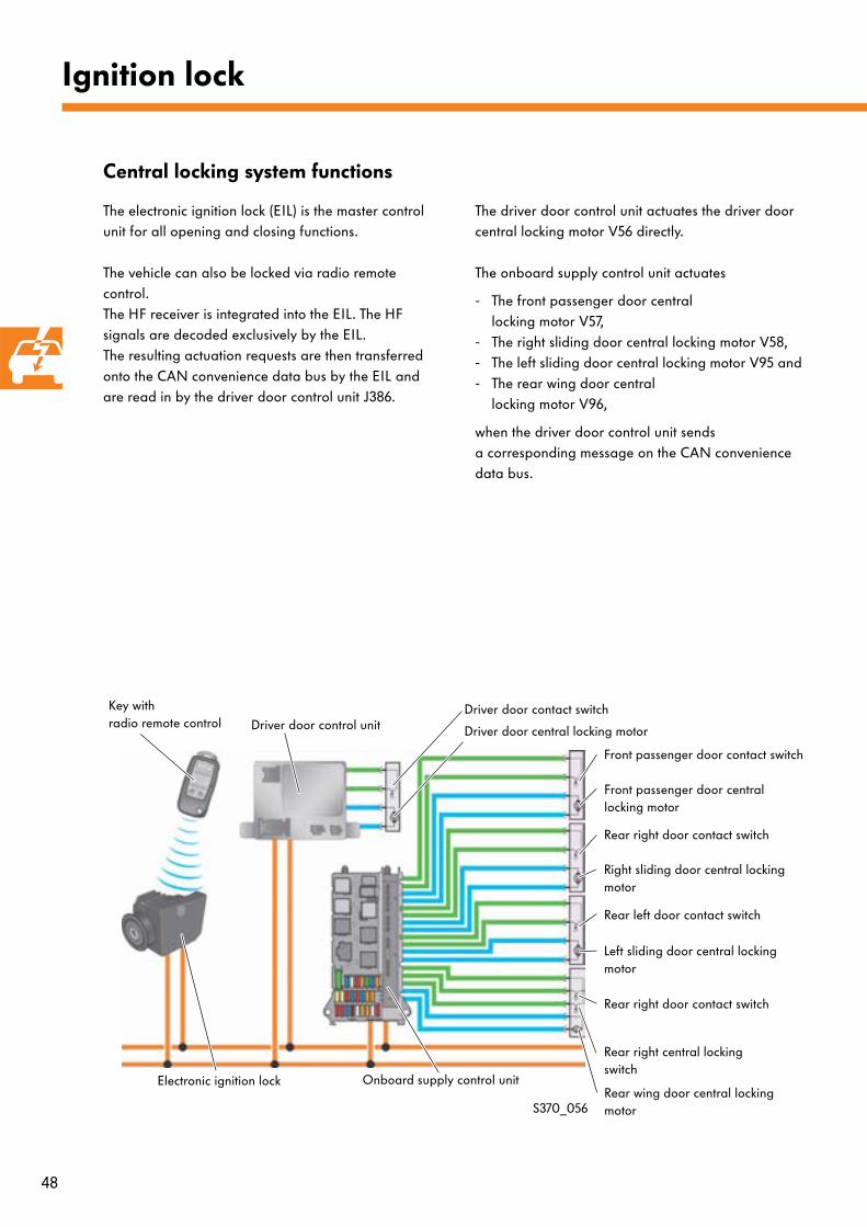
The electronic ignition lock (EIL) is the master control unit for all opening and closing functions.
The vehicle can also be locked via radio remote control. The HF receiver is integrated into the EIL. The HF signals are decoded exclusively by the EIL. The resulting actuation requests are then transferred onto the CAN convenience data bus by the EIL and are read in by the driver door control unit J386.
The driver door control unit actuates the driver door central locking motor V56 directly.
The onboard supply control unit actuates
- The front passenger door central locking motor V57,
- The right sliding door central locking motor V58, - The left sliding door central locking motor V95 and - The rear wing door central
locking motor V96,
when the driver door control unit sends a corresponding message on the CAN convenience data bus.
Central locking system functions
S370_056
Key with radio remote control
Electronic ignition lock
Driver door control unit
Onboard supply control unit
Front passenger door central locking motor
Right sliding door central locking motor
Left sliding door central locking motor
Rear wing door central locking motor
Driver door central locking motor
Driver door contact switch
Front passenger door contact switch
Rear right door contact switch
Rear left door contact switch
Rear right central locking switch
Rear right door contact switch
49
Diagnostic interface function
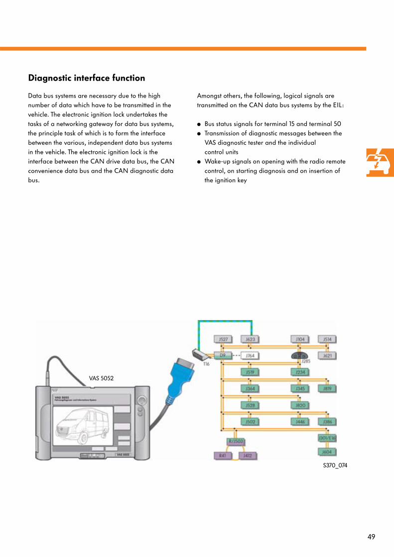
Data bus systems are necessary due to the high number of data which have to be transmitted in the vehicle. The electronic ignition lock undertakes the tasks of a networking gateway for data bus systems, the principle task of which is to form the interface between the various, independent data bus systems in the vehicle. The electronic ignition lock is the interface between the CAN drive data bus, the CAN convenience data bus and the CAN diagnostic data bus.
Amongst others, the following, logical signals are transmitted on the CAN data bus systems by the EIL:
● Bus status signals for terminal 15 and terminal 50● Transmission of diagnostic messages between the
VAS diagnostic tester and the individual control units
● Wake-up signals on opening with the radio remote control, on starting diagnosis and on insertion of the ignition key
S370_074
VAS 5052
50
Anti-theft system
Electronic steering column lock control unit J764
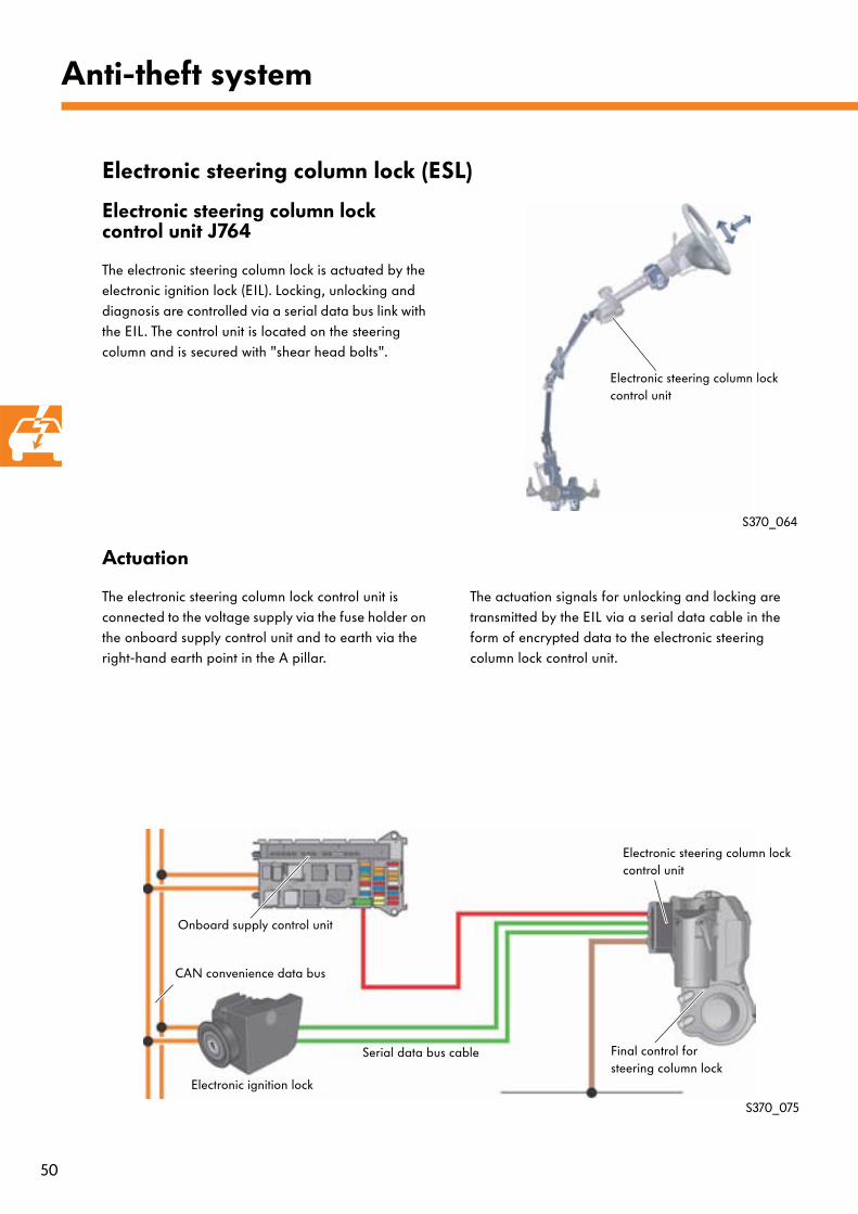
The electronic steering column lock is actuated by the electronic ignition lock (EIL). Locking, unlocking and diagnosis are controlled via a serial data bus link with the EIL. The control unit is located on the steering column and is secured with "shear head bolts".
Electronic steering column lock (ESL)
Actuation
The electronic steering column lock control unit is connected to the voltage supply via the fuse holder on the onboard supply control unit and to earth via the right-hand earth point in the A pillar.
The actuation signals for unlocking and locking are transmitted by the EIL via a serial data cable in the form of encrypted data to the electronic steering column lock control unit.
S370_064
S370_075
Onboard supply control unit
Electronic ignition lock
Electronic steering column lock control unit
Final control for steering column lock
Serial data bus cable
CAN convenience data bus
Electronic steering column lock control unit
51
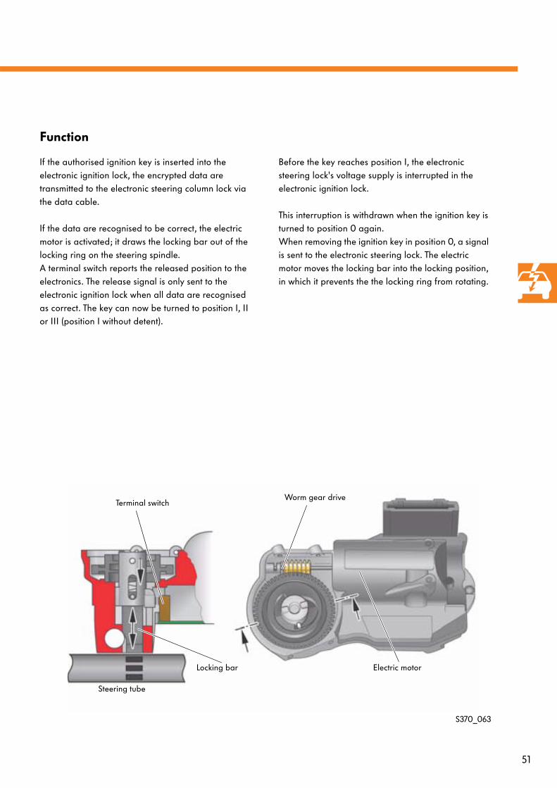
Function
If the authorised ignition key is inserted into the electronic ignition lock, the encrypted data are transmitted to the electronic steering column lock via the data cable.
If the data are recognised to be correct, the electric motor is activated; it draws the locking bar out of the locking ring on the steering spindle. A terminal switch reports the released position to the electronics. The release signal is only sent to the electronic ignition lock when all data are recognised as correct. The key can now be turned to position I, II or III (position I without detent).
Before the key reaches position I, the electronic steering lock's voltage supply is interrupted in the electronic ignition lock.
This interruption is withdrawn when the ignition key is turned to position 0 again. When removing the ignition key in position 0, a signal is sent to the electronic steering lock. The electric motor moves the locking bar into the locking position, in which it prevents the the locking ring from rotating.
S370_063
Electric motor
Worm gear drive
Locking bar
Terminal switch
Steering tube
52
Anti-theft system
Anti-theft alarm system
Description
The anti-theft alarm system is available as an option. Its functions are distributed amongst several control units. The master function is undertaken by the roof electronics control unit J528; it is linked to all of the other involved control units via the CAN data bus.
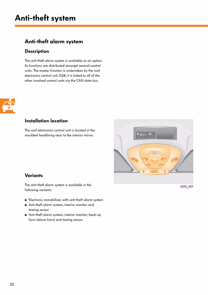
Installation location
The roof electronics control unit is located in the moulded headlining near to the interior mirror.
Variants
The anti-theft alarm system is available in the following variants:
● Electronic immobilizer, with anti-theft alarm system● Anti-theft alarm system, interior monitor and
towing sensor● Anti-theft alarm system, interior monitor, back-up
horn (alarm horn) and towing sensor
S370_057
53
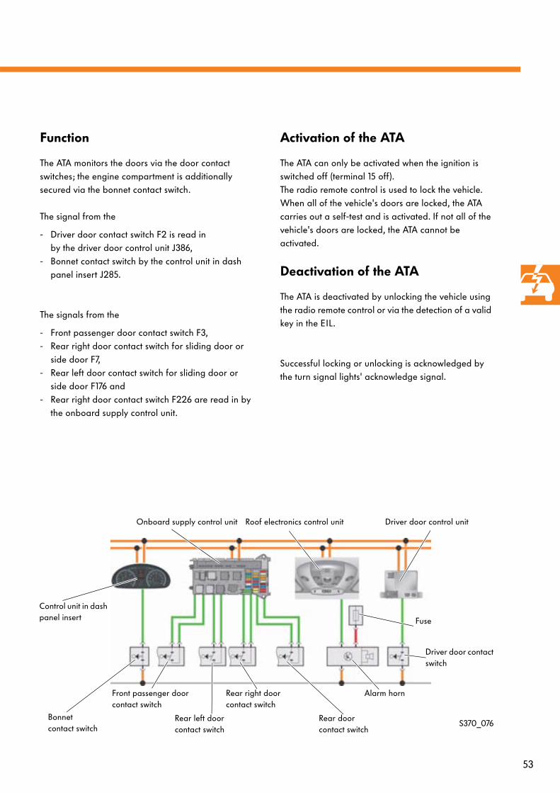
Function
The ATA monitors the doors via the door contact switches; the engine compartment is additionally secured via the bonnet contact switch.
The signal from the
- Driver door contact switch F2 is read in by the driver door control unit J386,
- Bonnet contact switch by the control unit in dash panel insert J285.
The signals from the
- Front passenger door contact switch F3,- Rear right door contact switch for sliding door or
side door F7, - Rear left door contact switch for sliding door or
side door F176 and - Rear right door contact switch F226 are read in by
the onboard supply control unit.
Activation of the ATA
The ATA can only be activated when the ignition is switched off (terminal 15 off).The radio remote control is used to lock the vehicle. When all of the vehicle's doors are locked, the ATA carries out a self-test and is activated. If not all of the vehicle's doors are locked, the ATA cannot be activated.
Deactivation of the ATA
The ATA is deactivated by unlocking the vehicle using the radio remote control or via the detection of a valid key in the EIL.
Successful locking or unlocking is acknowledged by the turn signal lights' acknowledge signal.
S370_076Bonnet contact switch
Front passenger door contact switch
Rear left door contact switch
Rear right door contact switch
Rear door contact switch
Alarm horn
Driver door contact switch
Fuse
Control unit in dash panel insert
Onboard supply control unit Roof electronics control unit Driver door control unit
54
Anti-theft system
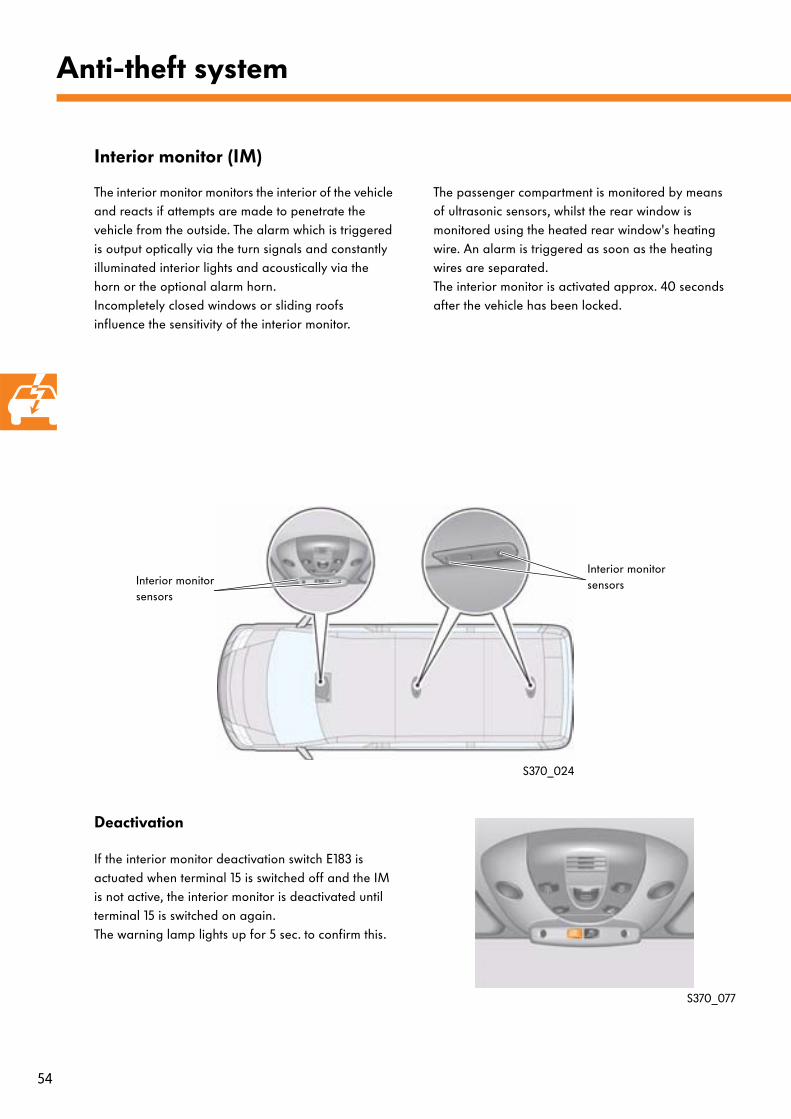
Interior monitor (IM)
The interior monitor monitors the interior of the vehicle and reacts if attempts are made to penetrate the vehicle from the outside. The alarm which is triggered is output optically via the turn signals and constantly illuminated interior lights and acoustically via the horn or the optional alarm horn. Incompletely closed windows or sliding roofs influence the sensitivity of the interior monitor.
The passenger compartment is monitored by means of ultrasonic sensors, whilst the rear window is monitored using the heated rear window's heating wire. An alarm is triggered as soon as the heating wires are separated. The interior monitor is activated approx. 40 seconds after the vehicle has been locked.
Deactivation
If the interior monitor deactivation switch E183 is actuated when terminal 15 is switched off and the IM is not active, the interior monitor is deactivated until terminal 15 is switched on again. The warning lamp lights up for 5 sec. to confirm this.
S370_024
S370_077
Interior monitor sensorsInterior monitor
sensors
55
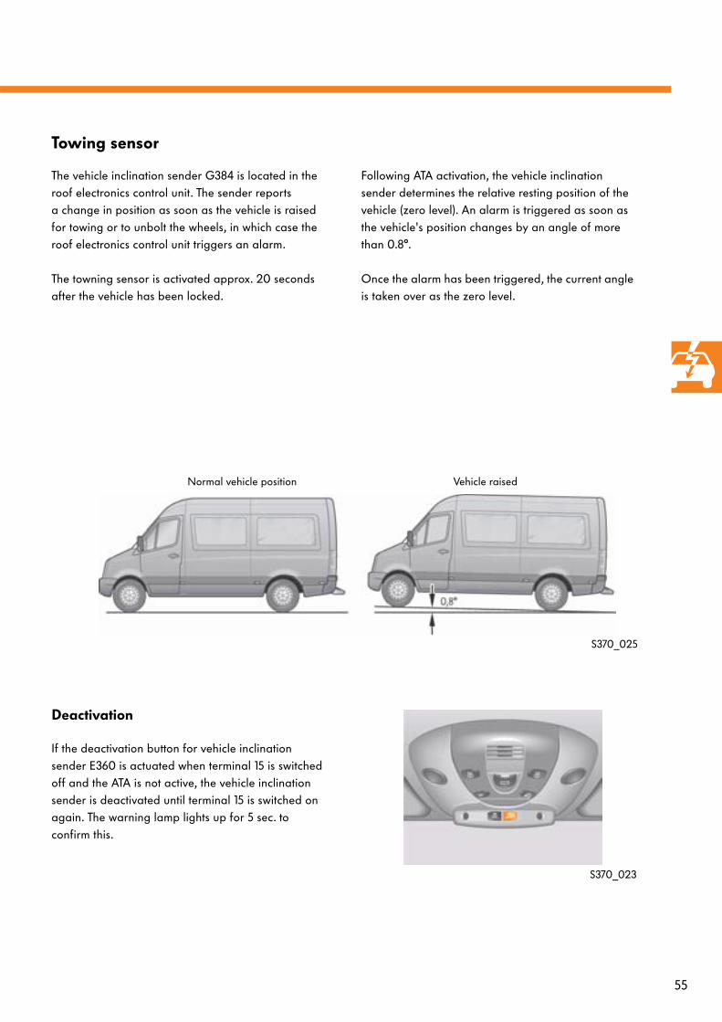
Towing sensor
The vehicle inclination sender G384 is located in the roof electronics control unit. The sender reports a change in position as soon as the vehicle is raised for towing or to unbolt the wheels, in which case the roof electronics control unit triggers an alarm.
The towning sensor is activated approx. 20 seconds after the vehicle has been locked.
Following ATA activation, the vehicle inclination sender determines the relative resting position of the vehicle (zero level). An alarm is triggered as soon as the vehicle's position changes by an angle of more than 0.8°.
Once the alarm has been triggered, the current angle is taken over as the zero level.
Deactivation
If the deactivation button for vehicle inclination sender E360 is actuated when terminal 15 is switched off and the ATA is not active, the vehicle inclination sender is deactivated until terminal 15 is switched on again. The warning lamp lights up for 5 sec. to confirm this.
S370_025
S370_023
Normal vehicle position Vehicle raised
56
Dash panel
Control unit in dash panel insert
Variants
The control unit in dash panel insert J285 is available in
- Low line and - High line variants.
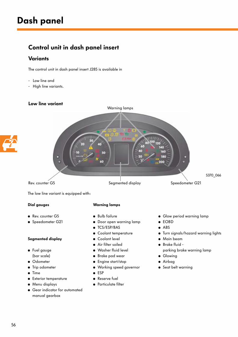
Low line variant
Rev. counter G5 Speedometer G21
The low line variant is equipped with:
Dial gauges
● Rev. counter G5● Speedometer G21
Segmented display
● Fuel gauge(bar scale)
● Odometer● Trip odometer● Time● Exterior temperature● Menu displays● Gear indicator for automated
manual gearbox
Warning lamps
● Bulb failure● Door open warning lamp● TCS/ESP/BAS● Coolant temperature● Coolant level● Air filter soiled● Washer fluid level● Brake pad wear● Engine start/stop● Working speed governor● ESP● Reserve fuel● Particulate filter
● Glow period warning lamp● EOBD● ABS● Turn signals/hazard warning lights● Main beam● Brake fluid -
parking brake warning lamp● Glowing● Airbag● Seat belt warning
Segmented display
Warning lamps
S370_066
57
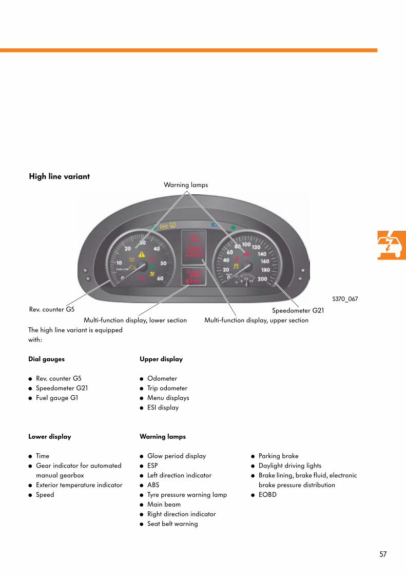
High line variant
Rev. counter G5 Speedometer G21Multi-function display, lower section
Warning lamps
The high line variant is equipped with:
Dial gauges
● Rev. counter G5● Speedometer G21● Fuel gauge G1
Lower display
● Time● Gear indicator for automated
manual gearbox● Exterior temperature indicator● Speed
Upper display
● Odometer● Trip odometer● Menu displays● ESI display
Warning lamps
● Glow period display● ESP● Left direction indicator● ABS● Tyre pressure warning lamp● Main beam● Right direction indicator● Seat belt warning
● Parking brake● Daylight driving lights● Brake lining, brake fluid, electronic
brake pressure distribution● EOBD
Multi-function display, upper section
S370_067
58
Dash panel
In the low line variant, the following menus can be called up by actuating the "menu button" in the segmented display:
Menu display in low line variant
● Read service date Actuate the menu button until the remaining distance in kilometres or the remaining time in days is displayed.
● Pre-select/set auxiliary heater activation time Actuate the menu button until the "auxiliary heater" symbol is shown in the segmented display; a pre-set starting time can then be selected with the + or - button.
● Set time Actuate the menu button until the hours display flashes. The + and - buttons can then be used to set the hour. The minutes display can then be set via the reset button and the + and - buttons.
● Set date Actuate the menu button until the day display flashes. The + and - buttons can then be used to set the day. The month and year display can then be set via the reset button and the + and - buttons.
59
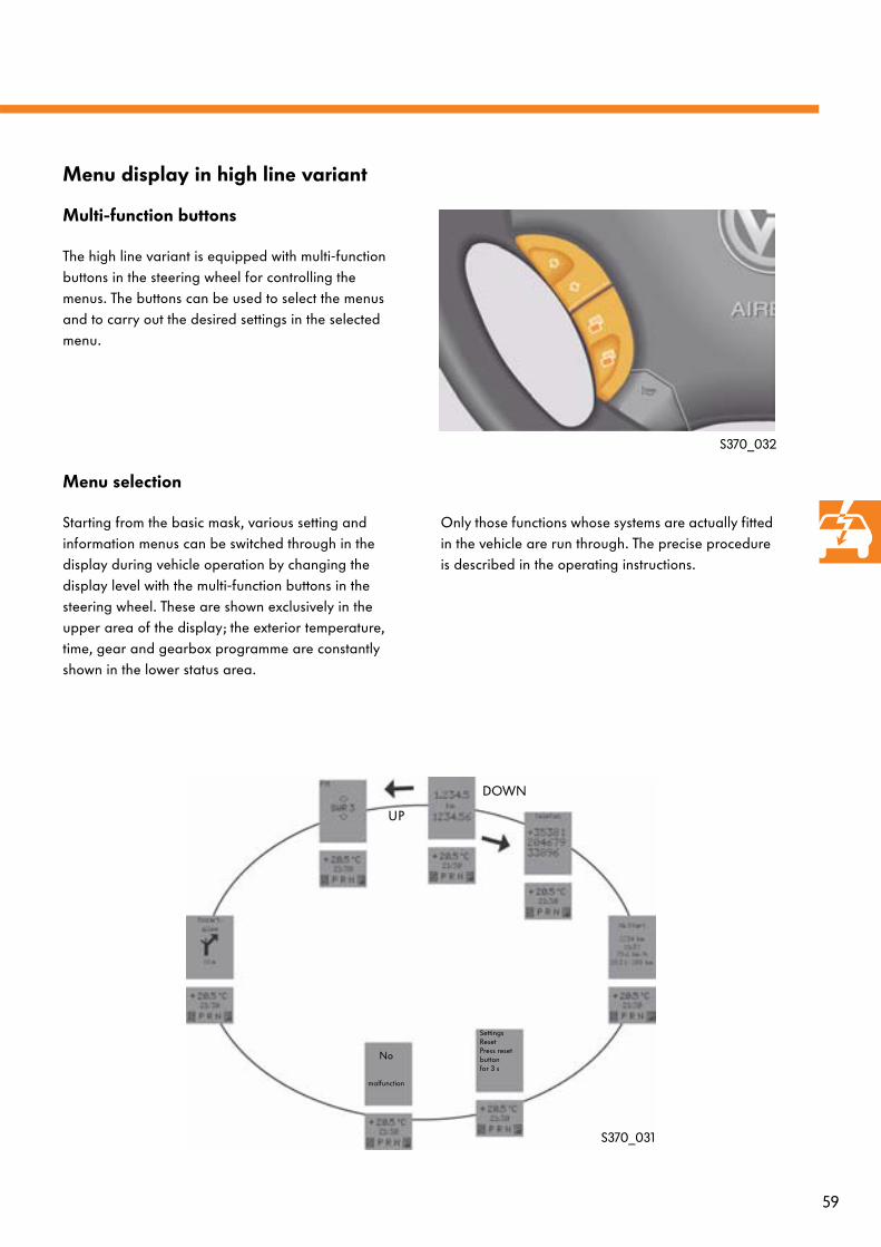
Multi-function buttons
The high line variant is equipped with multi-function buttons in the steering wheel for controlling the menus. The buttons can be used to select the menus and to carry out the desired settings in the selected menu.
Menu display in high line variant
Menu selection
Starting from the basic mask, various setting and information menus can be switched through in the display during vehicle operation by changing the display level with the multi-function buttons in the steering wheel. These are shown exclusively in the upper area of the display; the exterior temperature, time, gear and gearbox programme are constantly shown in the lower status area.
Only those functions whose systems are actually fitted in the vehicle are run through. The precise procedure is described in the operating instructions.
S370_032
UP
DOWN
SettingsResetPress reset buttonfor 3 s
No
malfunction
S370_031
60
Convenience systems
Parking aid
Description
The Volkswagen Crafter can be optionally equipped with an ultrasound-based parking aid at the front and rear. The system can be manually deactivated using a button. The parking aid displays are located on the instrument panel and in the outside rear-view mirrors. If the distance between the vehicle and an obstacle is less than 40 cm, an acoustic warning is sounded.
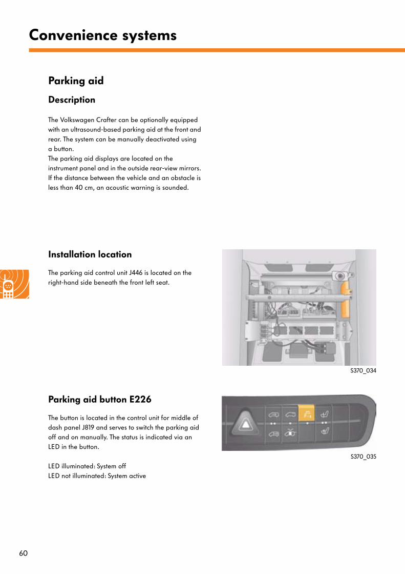
Installation location
The parking aid control unit J446 is located on the right-hand side beneath the front left seat.
Parking aid button E226
The button is located in the control unit for middle of dash panel J819 and serves to switch the parking aid off and on manually. The status is indicated via an LED in the button.
LED illuminated: System offLED not illuminated: System active
S370_034
S370_035
61
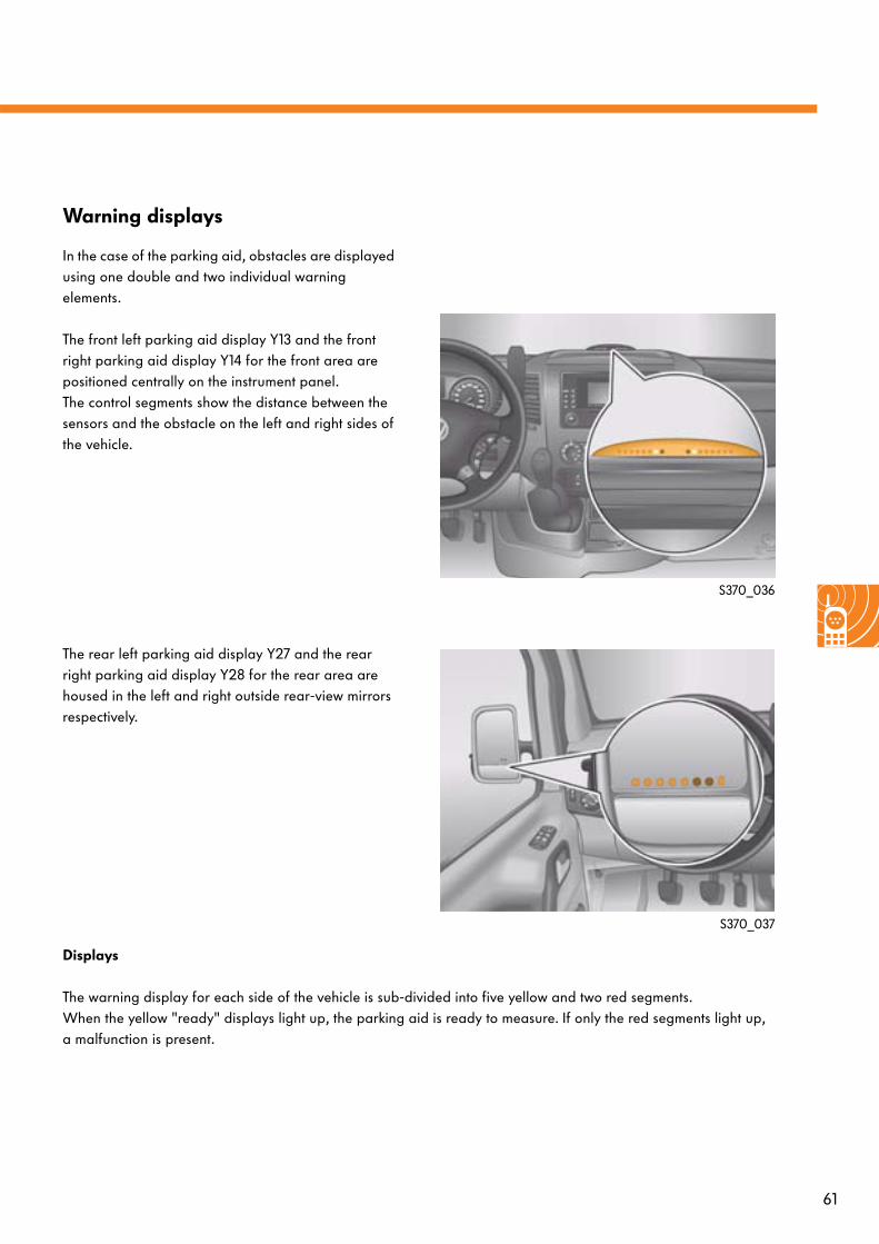
Warning displays
In the case of the parking aid, obstacles are displayed using one double and two individual warning elements.
The front left parking aid display Y13 and the front right parking aid display Y14 for the front area are positioned centrally on the instrument panel. The control segments show the distance between the sensors and the obstacle on the left and right sides of the vehicle.
The rear left parking aid display Y27 and the rear right parking aid display Y28 for the rear area are housed in the left and right outside rear-view mirrors respectively.
S370_036
S370_037
Displays
The warning display for each side of the vehicle is sub-divided into five yellow and two red segments. When the yellow "ready" displays light up, the parking aid is ready to measure. If only the red segments light up, a malfunction is present.
62
Convenience systems
Functional check
After the ignition has been switched on, "terminal 15 on", the parking aid control unit J446 actuates all parking aid displays for approx. 1 second. The correct function of the system is optically confirmed by the LEDs' lighting up.
The control unit, the sensors, the cables to the sensors, the parking aid displays and the cables to the displays are checked.
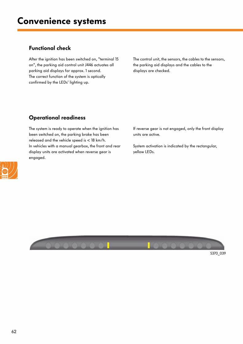
Operational readiness
The system is ready to operate when the ignition has been switched on, the parking brake has been released and the vehicle speed is < 18 km/h.In vehicles with a manual gearbox, the front and rear display units are activated when reverse gear is engaged.
If reverse gear is not engaged, only the front display units are active.
System activation is indicated by the rectangular, yellow LEDs.
S370_039
63
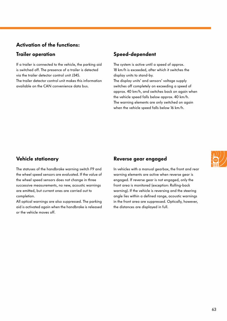
Trailer operation
If a trailer is connected to the vehicle, the parking aid is switched off. The presence of a trailer is detected via the trailer detector control unit J345.The trailer detector control unit makes this information available on the CAN convenience data bus.
Speed-dependent
The system is active until a speed of approx. 18 km/h is exceeded, after which it switches the display units to stand-by. The display units' and sensors' voltage supply switches off completely on exceeding a speed of approx. 40 km/h, and switches back on again when the vehicle speed falls below approx. 40 km/h. The warning elements are only switched on again when the vehicle speed falls below 16 km/h.
Vehicle stationary
The statuses of the handbrake warning switch F9 and the wheel speed sensors are evaluated. If the value of the wheel speed sensors does not change in three successive measurements, no new, acoustic warnings are emitted, but current ones are carried out to completion.All optical warnings are also suppressed. The parking aid is activated again when the handbrake is released or the vehicle moves off.
Reverse gear engaged
In vehicles with a manual gearbox, the front and rear warning elements are active when reverse gear is engaged. If reverse gear is not engaged, only the front area is monitored (exception: Rolling-back warning). If the vehicle is reversing and the steering angle lies within a defined range, acoustic warnings in the front area are suppressed. Optically, however, the distances are displayed in full.
Activation of the functions:
64
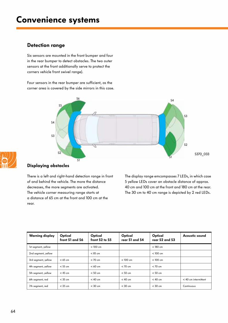
Warning display Opticalfront S1 and S6
Opticalfront S2 to S5
Opticalrear S1 and S4
Opticalrear S2 and S3
Acoustic sound
1st segment, yellow < 100 cm < 180 cm
2nd segment, yellow < 85 cm < 100 cm
3rd segment, yellow < 65 cm < 70 cm < 100 cm < 100 cm
4th segment, yellow < 55 cm < 60 cm < 70 cm < 70 cm
5th segment, yellow < 45 cm < 50 cm < 50 cm < 50 cm
6th segment, red < 35 cm < 40 cm < 40 cm < 40 cm < 40 cm intermittent
7th segment, red < 25 cm < 30 cm < 30 cm < 30 cm Continuous
Convenience systems
Detection range
Six sensors are mounted in the front bumper and four in the rear bumper to detect obstacles. The two outer sensors at the front additionally serve to protect the corners vehicle front swivel range).
Four sensors in the rear bumper are sufficient, as the corner area is covered by the side mirrors in this case.
S370_033
S1
S2
S3
S6
S5
S4
S1
S2
S3
S4
Displaying obstacles
There is a left and right-hand detection range in front of and behind the vehicle. The more the distance decreases, the more segments are activated. The vehicle corner measuring range starts at a distance of 65 cm at the front and 100 cm at the rear.
The display range emcompasses 7 LEDs, in which case 5 yellow LEDs cover an obstacle distance of approx. 40 cm and 100 cm at the front and 180 cm at the rear. The 30 cm to 40 cm range is depicted by 2 red LEDs.
65
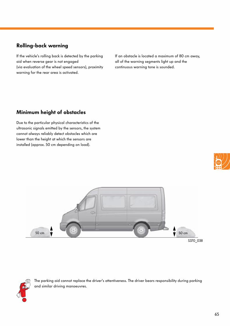
Rolling-back warning
If the vehicle's rolling back is detected by the parking aid when reverse gear is not engaged (via evaluation of the wheel speed sensors), proximity warning for the rear area is activated.
If an obstacle is located a maximum of 80 cm away, all of the warning segments light up and the continuous warning tone is sounded.
Minimum height of obstacles
Due to the particular physical characteristics of the ultrasonic signals emitted by the sensors, the system cannot always reliably detect obstacles which are lower than the height at which the sensors are installed (approx. 50 cm depending on load).
S370_038
50 cm 50 cm
The parking aid cannot replace the driver's attentiveness. The driver bears responsibility during parking and similar driving manoeuvres.
66
Convenience systems
Tyre pressure monitor
Function
The tyre pressure monitor serves to constantly monitor the tyre inflation pressure during vehicle operation. At certain intervals, the tyre pressure of each wheel is recorded by the tyre pressure sensors G222 - G225 and is transmitted, via the front and rear tyre pressure monitor aerials, R95 and R96, and a LIN data bus link, to the tyre pressure monitor control unit J502.
In the event of pressure loss, a warning message is indicated in the upper section of the multi-function display and via the tyre pressure warning lamp K230.
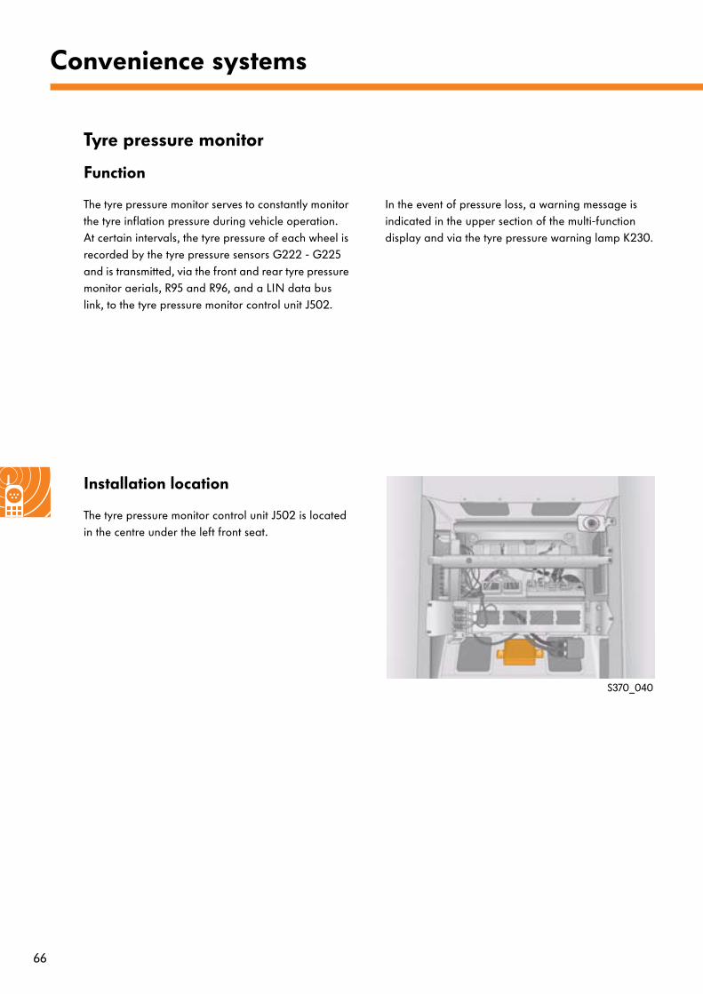
Installation location
The tyre pressure monitor control unit J502 is located in the centre under the left front seat.
S370_040
67
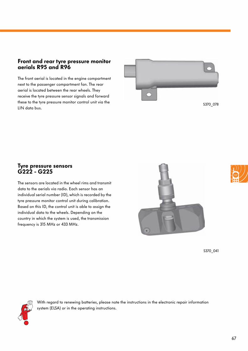
Tyre pressure sensors G222 - G225
The sensors are located in the wheel rims and transmit data to the aerials via radio. Each sensor has an individual serial number (ID), which is recorded by the tyre pressure monitor control unit during calibration. Based on this ID, the control unit is able to assign the individual data to the wheels. Depending on the country in which the system is used, the transmission frequency is 315 MHz or 433 MHz.
S370_041
Front and rear tyre pressure monitor aerials R95 and R96
The front aerial is located in the engine compartment next to the passenger compartment fan. The rear aerial is located between the rear wheels. They receive the tyre pressure sensor signals and forward these to the tyre pressure monitor control unit via the LIN data bus.
S370_078
With regard to renewing batteries, please note the instructions in the electronic repair information system (ELSA) or in the operating instructions.
68
Convenience systems
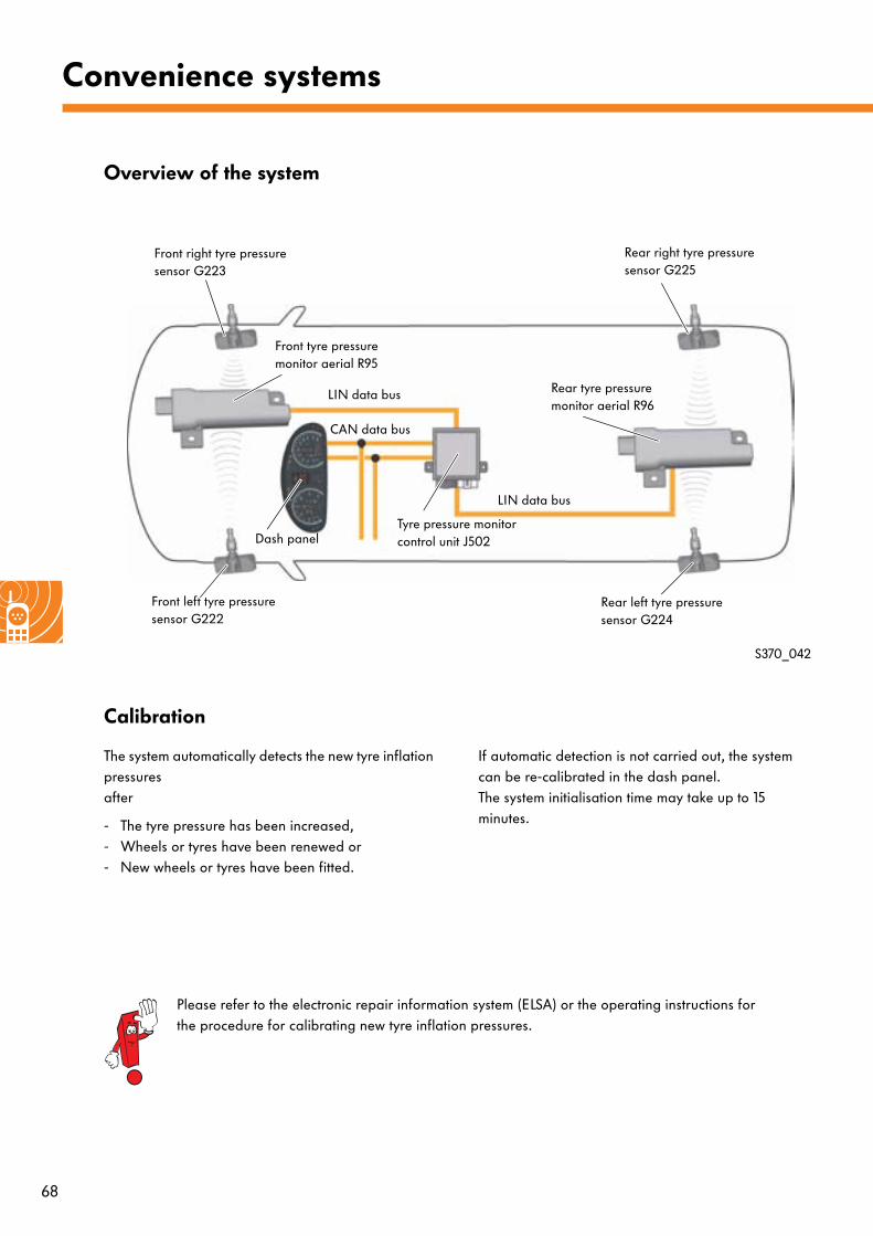
Overview of the system
S370_042
Front left tyre pressure sensor G222
Front right tyre pressure sensor G223
Rear left tyre pressure sensor G224
Rear right tyre pressure sensor G225
Front tyre pressure monitor aerial R95
Rear tyre pressure monitor aerial R96
Dash panelTyre pressure monitor control unit J502
LIN data bus
LIN data bus
CAN data bus
Calibration
The system automatically detects the new tyre inflation pressures after
- The tyre pressure has been increased,- Wheels or tyres have been renewed or - New wheels or tyres have been fitted.
If automatic detection is not carried out, the system can be re-calibrated in the dash panel. The system initialisation time may take up to 15 minutes.
Please refer to the electronic repair information system (ELSA) or the operating instructions for the procedure for calibrating new tyre inflation pressures.
69
Warnings
Soft warning
The operating status "soft warning" describes a pressure loss in which operating safety is still guaranteed. At the end of the journey, a request for the driver to correct the tyre inflation pressure at the next opportunity appears in the upper section of the multi-function display. This message is displayed for approx. 30 sec. when the ignition is switched off ("terminal 15 off").
The "soft warning" is triggered when the temperature-compensated tyre pressure has fallen by more than 0.25 bar in comparison with the inflation pressure. No single tyre is specified; all tyre pressures have to be checked.
Hard warning
The operating status "hard warning" describes a pressure loss in which operating safety is no longer fully guaranteed. In the upper section of the multi-function display, the driver is requested, during vehicle operation, to check the tyres.
A "hard warning" is triggered when one of the following conditions is met:
● The tyre pressure falls below 2.6 bar.● The tyre pressure falls by 20% in comparison with
the inflation pressure (max. 0.5 bar).
In parallel with the "hard warning", the tyre pressure warning lamp is actuated. This actuation is only withdrawn following re-activation of the system or when pressure correction has been determined by the system.
The warning is displayed until the ignition is switched off (terminal 15 off).
If the ignition is switched off and on again, the tyre pressure warning lamp is actuated immediately. The warning in the upper section of the multi-function display is active again after travelling for approx. 5 min.
In the case of the "hard warning" operating status, the affected tyre is specified in the multi-function display.
70
Convenience systems
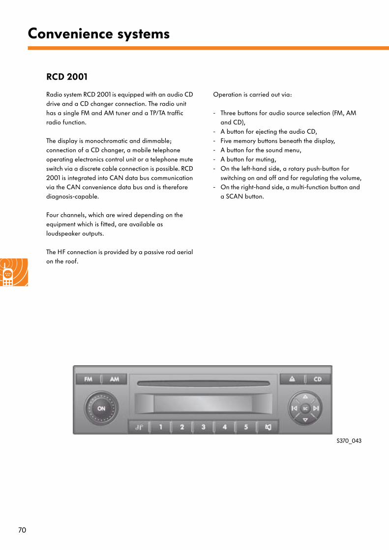
RCD 2001
Radio system RCD 2001 is equipped with an audio CD drive and a CD changer connection. The radio unit has a single FM and AM tuner and a TP/TA traffic radio function.
The display is monochromatic and dimmable; connection of a CD changer, a mobile telephone operating electronics control unit or a telephone mute switch via a discrete cable connection is possible. RCD 2001 is integrated into CAN data bus communication via the CAN convenience data bus and is therefore diagnosis-capable.
Four channels, which are wired depending on the equipment which is fitted, are available as loudspeaker outputs.
The HF connection is provided by a passive rod aerial on the roof.
Operation is carried out via:
- Three buttons for audio source selection (FM, AM and CD),
- A button for ejecting the audio CD, - Five memory buttons beneath the display,- A button for the sound menu,- A button for muting,- On the left-hand side, a rotary push-button for
switching on and off and for regulating the volume,- On the right-hand side, a multi-function button and
a SCAN button.
S370_043
71
S370_045
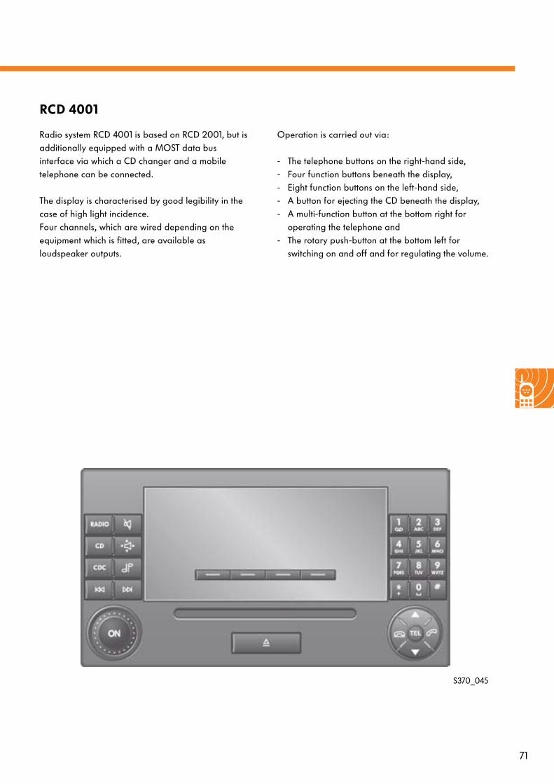
RCD 4001
Radio system RCD 4001 is based on RCD 2001, but is additionally equipped with a MOST data bus interface via which a CD changer and a mobile telephone can be connected.
The display is characterised by good legibility in the case of high light incidence. Four channels, which are wired depending on the equipment which is fitted, are available as loudspeaker outputs.
Operation is carried out via:
- The telephone buttons on the right-hand side,- Four function buttons beneath the display,- Eight function buttons on the left-hand side,- A button for ejecting the CD beneath the display, - A multi-function button at the bottom right for
operating the telephone and - The rotary push-button at the bottom left for
switching on and off and for regulating the volume.
72
Convenience systems
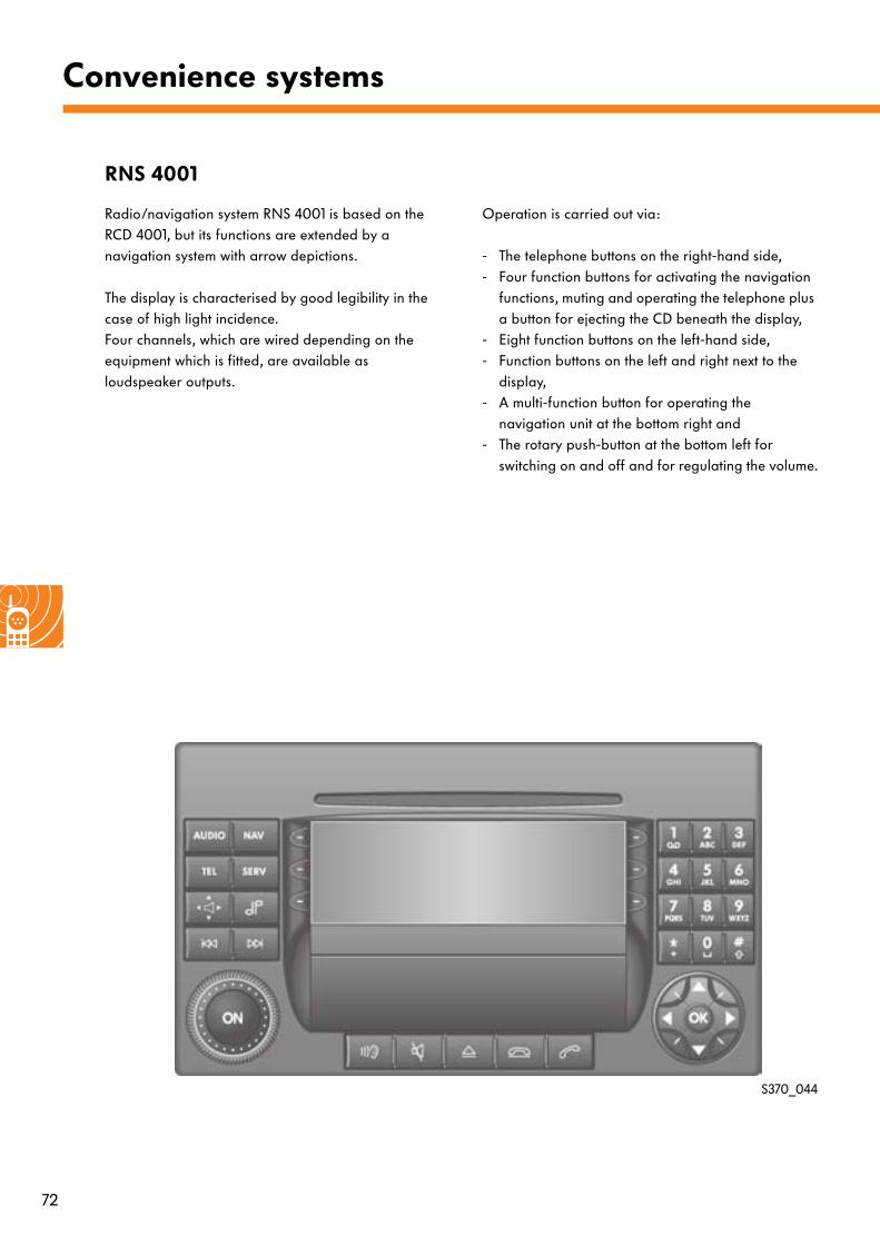
RNS 4001
Radio/navigation system RNS 4001 is based on the RCD 4001, but its functions are extended by a navigation system with arrow depictions.
The display is characterised by good legibility in the case of high light incidence. Four channels, which are wired depending on the equipment which is fitted, are available as loudspeaker outputs.
Operation is carried out via:
- The telephone buttons on the right-hand side,- Four function buttons for activating the navigation
functions, muting and operating the telephone plus a button for ejecting the CD beneath the display,
- Eight function buttons on the left-hand side,- Function buttons on the left and right next to the
display,- A multi-function button for operating the
navigation unit at the bottom right and - The rotary push-button at the bottom left for
switching on and off and for regulating the volume.
S370_044
73
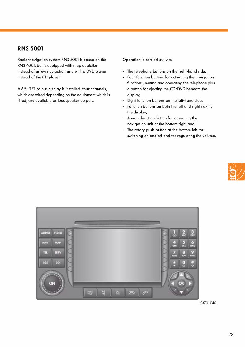
RNS 5001
Radio/navigation system RNS 5001 is based on the RNS 4001, but is equipped with map depiction instead of arrow navigation and with a DVD player instead of the CD player.
A 6.5'' TFT colour display is installed; four channels, which are wired depending on the equipment which is fitted, are available as loudspeaker outputs.
Operation is carried out via:
- The telephone buttons on the right-hand side,- Four function buttons for activating the navigation
functions, muting and operating the telephone plus a button for ejecting the CD/DVD beneath the display,
- Eight function buttons on the left-hand side,- Function buttons on both the left and right next to
the display,- A multi-function button for operating the
navigation unit at the bottom right and - The rotary push-button at the bottom left for
switching on and off and for regulating the volume.
S370_046
74
Convenience systems
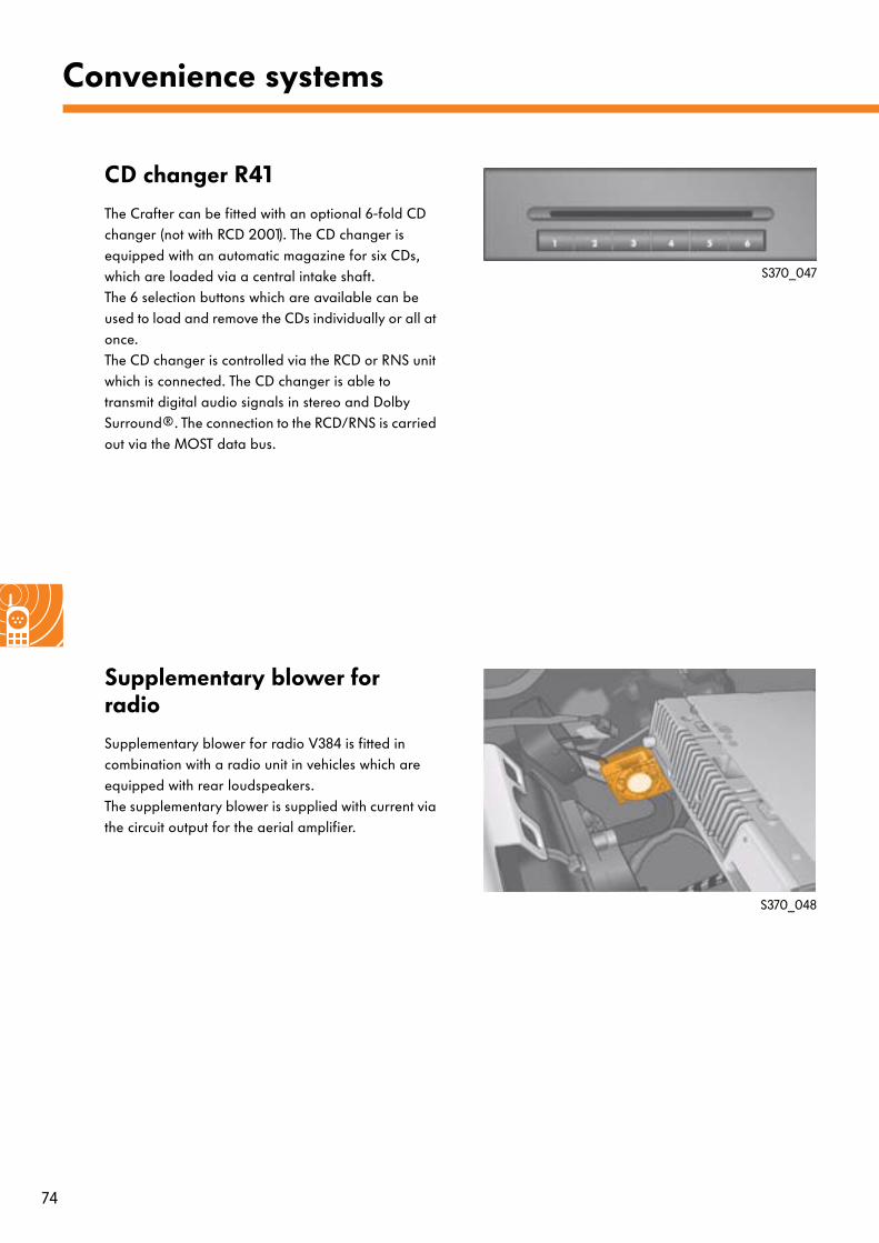
CD changer R41
The Crafter can be fitted with an optional 6-fold CD changer (not with RCD 2001). The CD changer is equipped with an automatic magazine for six CDs, which are loaded via a central intake shaft. The 6 selection buttons which are available can be used to load and remove the CDs individually or all at once. The CD changer is controlled via the RCD or RNS unit which is connected. The CD changer is able to transmit digital audio signals in stereo and Dolby Surround®. The connection to the RCD/RNS is carried out via the MOST data bus.
Supplementary blower for radio
Supplementary blower for radio V384 is fitted in combination with a radio unit in vehicles which are equipped with rear loudspeakers. The supplementary blower is supplied with current via the circuit output for the aerial amplifier.
S370_047
S370_048
75
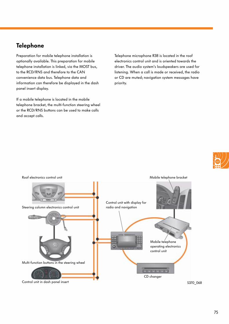
Telephone
Preparation for mobile telephone installation is optionally available. This preparation for mobile telephone installation is linked, via the MOST bus, to the RCD/RNS and therefore to the CAN convenience data bus. Telephone data and information can therefore be displayed in the dash panel insert display.
If a mobile telephone is located in the mobile telephone bracket, the multi-function steering wheel or the RCD/RNS buttons can be used to make calls and accept calls.
Telephone microphone R38 is located in the roof electronics control unit and is oriented towards the driver. The audio system's loudspeakers are used for listening. When a call is made or received, the radio or CD are muted; navigation system messages have priority.
S370_068
Roof electronics control unit
Steering column electronics control unit
Multi-function buttons in the steering wheel
Control unit in dash panel insert
Mobile telephone operating electronics control unit
CD changer
Mobile telephone bracket
Control unit with display for radio and navigation
76
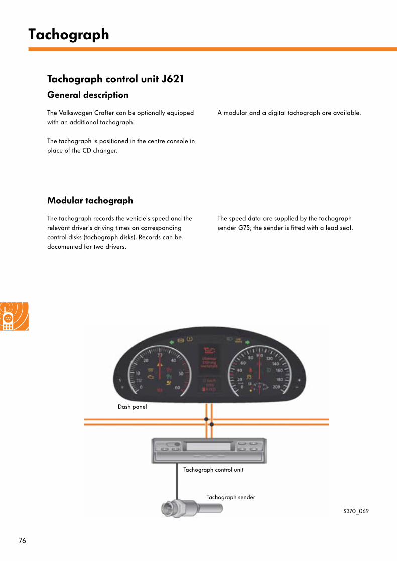
Tachograph
Tachograph control unit J621General description
The Volkswagen Crafter can be optionally equipped with an additional tachograph.
The tachograph is positioned in the centre console in place of the CD changer.
A modular and a digital tachograph are available.
Modular tachograph
The tachograph records the vehicle's speed and the relevant driver's driving times on corresponding control disks (tachograph disks). Records can be documented for two drivers.
The speed data are supplied by the tachograph sender G75; the sender is fitted with a lead seal.
S370_069
Tachograph sender
Tachograph control unit
Dash panel
77
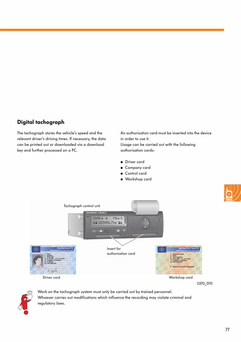
Digital tachograph
The tachograph stores the vehicle's speed and the relevant driver's driving times. If necessary, the data can be printed out or downloaded via a download key and further processed on a PC.
An authorisation card must be inserted into the device in order to use it. Usage can be carried out with the following authorisation cards:
● Driver card● Company card● Control card● Workshop card
S370_070
Work on the tachograph system must only be carried out by trained personnel.Whoever carries out modifications which influence the recording may violate criminal and regulatory laws.
Tachograph control unit
Driver card Workshop card
Insert for authorisation card
78
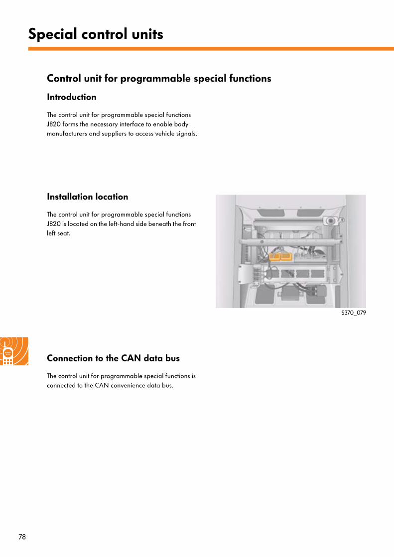
Special control units
Control unit for programmable special functions
Introduction
The control unit for programmable special functions J820 forms the necessary interface to enable body manufacturers and suppliers to access vehicle signals.
Installation location
The control unit for programmable special functions J820 is located on the left-hand side beneath the front left seat.
Connection to the CAN data bus
The control unit for programmable special functions is connected to the CAN convenience data bus.
S370_079
79
Function
The control unit for programmable special functions undertakes the tasks of a bi-directional gateway for vehicle and body part information. This therefore enables body-related intervention, e.g. into engine functions (constant speed maintenance), or CAN data bus information can be output (e.g. lighting or vehicle speed).
Programming is carried out using the vehicle diagnosis, testing and information system VAS 5051 B or vehicle diagnosis and service information system VAS 5052 in the service department or directly at the body manufacturer's or supplier's premises according to defined specifications.
The contents of the CAN data bus messages are used as the basis of the control unit functions. Via this, the control unit obtains information on the vehicle's status. This information is forwarded to the control unit's corresponding outputs and is processed by the body's electronic components.
The control unit for programmable special functions may also be used to actively intervene into the vehicle electronics.
The requests which the control unit receives via
- Discrete inputs or - The data bus used by the body manufacturer
are forwarded via the CAN convenience data bus.
The control unit for programmable special functions is integrated into Guided Fault Finding for diagnostic purposes.
Please refer to the electronic repair information system (ELSA) and the body manufacturer's customer service documents for further information on the control unit for programmable special functions.
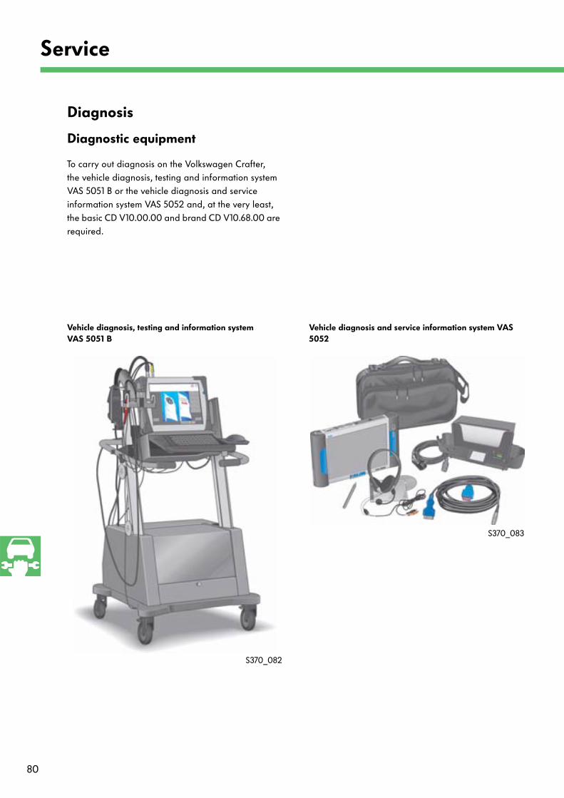
80
Service
Diagnosis
Diagnostic equipment
To carry out diagnosis on the Volkswagen Crafter, the vehicle diagnosis, testing and information system VAS 5051 B or the vehicle diagnosis and service information system VAS 5052 and, at the very least, the basic CD V10.00.00 and brand CD V10.68.00 are required.
S370_083
S370_082
Vehicle diagnosis, testing and information systemVAS 5051 B
Vehicle diagnosis and service information system VAS 5052
81
Adapting control units
Control units which it is sensible to retrofit (e.g. trailer detector control unit, auxiliary heater control unit) can be adapted in the electronic ignition lock by means of variant coding. Participation in communication with other control units which are installed in the vehicle via the CAN data bus systems is only possible following adaptation.
On-line adaptation
An on-line link to the vehicle manufacturer's server is required to adapt the following control units following renewal:
● Engine control unit J623● Airbag control unit J234● Electronic steering column lock control unit J764● Electronic ignition lock D9● Keys
Renewal of immobilizer components
The following electronic components are immobilizer components:
● Engine control unit● Electronic steering column lock control unit● Electronic ignition lock● Transponder in the ignition key
Only two of these components can be renewed at the same time. On-line adaptation then has to be carried out. If it is necessary to renew more than two components (e.g. following an accident) at the same time, all components must be renewed and must subsequently be adapted via an on-line link to the manufacturer.
82
Glossary
ADL/Auto
Automatic driving lights
OBSCU
Onboard supply control unit
CAN
Controller Area Network
ATA
Anti-theft alarm system
EIL
Electronic ignition lock
DAS
Drive authorisation system
CCS
Cruise control system
IM
Interior monitor
LIN data bus link
Local Interconnect Network (see SSP 286)
DDL
Daylight driving lights
ESI
Extended servicing intervals
Voltage-coded light switch
The voltage input into the light switch is changed in such a way by means of internal resistors that a voltage value can be assigned to each switch position. Based on these voltage values, the reading control unit recognises the selected switch position.
83
Test yourself
1.) Which data transmission rates do not exist in the Crafter?
a) 500 kbit/s
b) 100 kbit/s
c) 83.3 kbit/s
d) 50 kbit/s
2.) Via which control unit are the bus systems linked together?
a) J533 – data bus diagnostic interface
b) J285 – control unit in dash panel insert
c) D9 – electronic ignition lock
d) T16 – 16-pin connector (diagnostic connector)
3.) Which components do not belong to the CAN drive data bus?
a) J234 – airbag control unit
b) J104 – ABS control unit
c) J623 – engine control unit
d) J527 – steering column electronics control unit
Answers: 1 b; d; 2 c; 3 a
370
© VOLKSWAGEN AG, WolfsburgAll rights and rights to make technical alterations reserved.000.2811.77.20 Technical status 03.2006
Volkswagen AGService Training VSQ-1Brieffach 1995D-38436 Wolfsburg
❀ This paper was manufactured from pulp that was bleached without the use of chlorine.