Embed Size (px)
Citation preview

Imaging system for hypervelocity dust injection diagnostic on NSTXL. A. Dorf, A. L. Roquemore, G. A. Wurden, C. M. Ticos, and Zhehui Wang Citation: Review of Scientific Instruments 77, 10E517 (2006); doi: 10.1063/1.2336790 View online: http://dx.doi.org/10.1063/1.2336790 View Table of Contents: http://scitation.aip.org/content/aip/journal/rsi/77/10?ver=pdfcov Published by the AIP Publishing Articles you may be interested in X-ray imaging crystal spectroscopy for use in plasma transport research Rev. Sci. Instrum. 83, 113504 (2012); 10.1063/1.4758281 A protection system for the JET ITER-like wall based on imaging diagnosticsa) Rev. Sci. Instrum. 83, 10D727 (2012); 10.1063/1.4738742 Imaging of high-speed dust particle trajectories on NSTX Rev. Sci. Instrum. 77, 10E526 (2006); 10.1063/1.2347696 Plasmadynamic hypervelocity dust injector for the National Spherical Torus Experiment Rev. Sci. Instrum. 77, 10E304 (2006); 10.1063/1.2219384 Hypervelocity dust beam injection for national spherical torus experiment Rev. Sci. Instrum. 75, 3436 (2004); 10.1063/1.1784529
This article is copyrighted as indicated in the article. Reuse of AIP content is subject to the terms at: http://scitationnew.aip.org/termsconditions. Downloaded to IP:
128.59.171.71 On: Wed, 10 Dec 2014 08:41:49
Imaging system for hypervelocity dust injection diagnostic on NSTXL. A. Dorf,a� A. L. Roquemore,b� G. A. Wurden, C. M. Ticos, and Zhehui WangLos Alamos National Laboratory, Los Alamos, New Mexico 87545
�Received 6 May 2006; presented on 8 May 2006; accepted 24 July 2006;published online 10 October 2006�
The novel hypervelocity dust injection diagnostic will facilitate our understanding of basic aspectsof dust-plasma interaction and magnetic field topology in fusion plasma devices, by observing“comet tails” associated with the injected micron-size dust particles. A single projection of the tailonto an image plane will not provide sufficient information; therefore, we plan to use two views,with intensified DiCam-Pro cameras on two NSTX ports. Each camera can furnish up to fiveoverlaying sequential images with gate times greater than 3 ns and 1280�1024 pixel resolution. Acoherent fiber bundle with 1500�1200 fibers will relay the image from an imaging lens installeddirectly on the port to the camera optics. The lens receives light from the outer portion of the NSTXcross section and focuses a 1 cm tail onto at least 60 fibers for adequate resolution. The estimatednumber of photons received by the camera indicates signal-to-noise ratios of 102–104, with the useof a 10 nm bandwidth filter. The imaging system with one camera was successfully tested on NSTXin 2005. Photographing lithium pellets yielded bright and distinctive pictures of the tails nearlyaligned with B lines. We also observed that the bright “filaments”—plasma cords with high densityand temperature—are present in both top and bottom portions of the machine. © 2006 AmericanInstitute of Physics. �DOI: 10.1063/1.2336790�
I. INTRODUCTION
Imaging cameras have been employed on ASDEX,TFTR, C-Mod, JET, and other plasma experiments.1–9 OnNSTX and other tokamaks, these systems have been used toexamine plasma wall interaction and macroscopic phenom-ena in the bulk plasma or divertor regions. Striation anglemeasurements have been utilized to infer plasma q profiles.10
Comprehensive studies of pellet ablation clouds were alsoperformed.1 Wide optical views are typically adequate forthese tasks, where ultrahigh spatial resolution is not required.
The imaging system for our novel hypervelocity dustinjection �HDI� diagnostic should be able to simultaneouslydetect ten or more optical tails associated with dustplumes.11–13 For micron-size dust particles, the plumes areexpected to be not more than 1 cm long �for pellet ablationclouds this number can be from several to several tens ofcentimeters�. The tails are expected to be aligned with localmagnetic field vectors inside the NSTX plasma. The particleswill be injected with the velocities of the order of1–10 km/s. A 100 ns gated exposure is therefore required tofreeze motion effects. The number of visible photons perpixel accumulated in the change-coupled device �CCD� dur-ing one exposure needs to be sufficient to produce an ad-equately defined image, and filters can be used to reduceplasma background light, as necessary. This forms the basisfor the dust imaging system design.
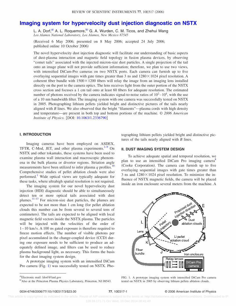
A prototype imaging system with an intensified DiCamPro camera �Fig. 1� was successfully tested on NSTX. Pho-
tographing lithium pellets yielded bright and distinctive pic-tures of the tails nearly aligned with B lines.
II. DUST IMAGING SYSTEM DESIGN
To achieve adequate spatial and temporal resolution, weplan to use an intensified DiCam Pro imaging camera8
�Cooke Corporation�. The camera can furnish up to fiveoverlaying sequential images with gate times greater than3 ns and 1280�1024 pixel resolution. To minimize the in-fluence of NSTX magnetic fields, the camera will be placedinside an iron enclosure several meters from the machine. A
a�Electronic mail: [email protected]�Also at the Princeton Plasma Physics Laboratory, Princeton, NJ 08543.
FIG. 1. A prototype imaging system with intensified DiCam Pro cameratested on NSTX in 2005 by observing lithium pellets ablation clouds.
REVIEW OF SCIENTIFIC INSTRUMENTS 77, 10E517 �2006�
0034-6748/2006/77�10�/10E517/3/$23.00 © 2006 American Institute of Physics77, 10E517-1
This article is copyrighted as indicated in the article. Reuse of AIP content is subject to the terms at: http://scitationnew.aip.org/termsconditions. Downloaded to IP:
128.59.171.71 On: Wed, 10 Dec 2014 08:41:49

coherent fiber bundle with 1500�1200 10�10 �m2 fibers21
�Schott Fiber Optics, Inc.� will relay the image from an im-aging lens installed directly on the port to the camera optics.A 36�24 mm2 rectangular image obtained from a 35 mmformat lens will overfill the 15�11 mm2 fiber bundle byabout two times. Therefore, to survey the outer portion��1/2� of the NSTX cross section, the field of view of theimaging lens should be such that the lens could collect lightfrom the entire cross section. A minimum object distance forthe lens should be about 25–30 cm. Since the position of adust particle inside the plasma at the time of exposure varies,a variable focus �zoom� lens needs to be employed. For alens with a depth of field of several to several tens of centi-meters �which is typical for commercially available lenses atmaximum aperture setting�, this will allow a dust tail with across section of a few millimeters and a length of 1 to a fewcentimeters to be always in focus at the time of exposure,and the image of the tail to be sufficiently large for obtaininga high-resolution picture.
To filter out the background light from the NSTXplasma, a narrow-band ��10 nm wide� interference filter canbe placed between the fiber bundle and the camera �i.e., inthe parallel beam of light between two image relay lenses inFig. 1�. The most dominant visible spectral lines for C I andC II are 426.7, 538, 601.3, and 657.8 nm, and for Li I andLi II they are 548.4, 548.6, and 670.8 nm, which determinesthe selection of the filter.
To estimate how deep a dust particle can penetrate intothe NSTX plasma and the number of photons emitted persecond due to ablation, we developed a time-dependent dustcharging model.14 Unlike a recent dust-particle transportmodel by Pigarov et al.,15 for example, our model considerstime evolution of the particle surface charge without assum-ing a floating potential at the particle surface, and works inboth orbital motion limited �OML� or sheath limited �SL�
regimes,16 i.e., for different relations between the particleradius and the Debye length. We assumed that a thick abla-tion cloud typical for pellets is not formed for dust. We alsoassumed that each sublimed atom is ionized once and onaverage and simplistically emits one photon. Figure 2 showsthe results of numerical simulations for a carbon dust par-ticle. We used Ti�Te, Te=Te0�1− �r /a�2�1.5, and ne=ne0�1− �r /a�2�0.5, where Te0=1000 eV is the peak electron tem-perature, ne0=5�1013 cm−3 is the peak plasma density, a=67 cm is the minor radius, and r=R−R0 is the particle’sradial position relative to the major radius, R0=90 cm.17–19
Using Fig. 2�a�, the maximum number of photons re-ceived by the lens during a 100 ns exposure can now beestimated as Nph
tot�1.4�1010 �, where �= �D /4S�2 is theratio between the solid angle of the lens and 4�, D is the
FIG. 2. Estimated number of atoms remaining in the carbon dust particleand number of photons emitted per second due to ablation vs particle’sradial position inside NSTX for two particle velocities.
FIG. 3. Plasma filaments observed during shots 116056 �a� and 116059 �b�are present in both top and bottom portions of NSTX. Exposure=25 �s,delay=200 ms �a� and 150 ms �b�.
FIG. 4. Pitch angle calculation from EFIT�02 program corresponds closely tothe measured value for Li pellet ablation cloud. The circle represents errorbars for the pellet’s radial position and calculated pitch angle.
10E517-2 Dorf et al. Rev. Sci. Instrum. 77, 10E517 �2006�
This article is copyrighted as indicated in the article. Reuse of AIP content is subject to the terms at: http://scitationnew.aip.org/termsconditions. Downloaded to IP:
128.59.171.71 On: Wed, 10 Dec 2014 08:41:49

diameter of the lens, and S is the distance between the lensand the dust particle. For D=5 cm and S=50 cm, we have�=6.25�10−4, and so Nph
tot�107. As an example consider a35 mm format Sigma 28–300 mm/F3.5–6.3 lens22 with adepth of field of about 40–60 cm at a 50 cm distance �for allfocal lengths and aperture settings� and a variable field ofview �FOV� of 8°–75°. Assume that a dust tail has a cigarshape with 10�2 mm2 characteristic dimensions, and that itis parallel to the long dimension of the lens image area �36�24 mm2�. Then the tail will be focused onto 60�12 �forFOV �60°� or 410�82 �for FOV �10°� fibers. A lens sys-tem then relays the image from 1500�1200 fibers onto1280�1024 pixels of the camera, so every 1.17�1.17 fibersfill out one pixel. Assume now that at each focal length�FOV� setting the lens is used at the maximum permissibleaperture setting, so that 90% or more �depending on the in-ternal properties of the lens� of the light reaching its frontsurface is focused onto the image plane. In view of theabove, the total number of photons received by each pixelduring one exposure can be estimated as Nph
tot/pix�4�102
−2�104. Comparing it to the number of photons fromplasma bremsstrahlung radiation, we estimate a signal-to-noise ratio �SNR� �104, with the 10 nm bandwidth, 427 nmC I filter in place, and SNR �250 without the filter. SinceNph
tot�dust��Te03/2 and Nph
tot�plasma��Te0−1/2, for a plasma with
Te0=100 eV, we obtain SNRs �102 and 2.5, respectively.
III. IMAGING SYSTEM TESTING ON NSTX
Figure 1 shows the schematic drawing of the prototypeimaging system deployed on NSTX in 2005. A C-mount6.5 mm/F1.8 fisheye fixed focus lens was placed in front ofthe 5.7 cm window at Bay K. It surveyed the right half-torusand the center stack of the machine, to photograph pelletablation clouds from behind. The camera was situated ap-proximately 4 m from Bay K. It was triggered by a TTL-level signal synchronized with the machine clock. The cam-era was coupled to the fisheye lens via a 5 m 1000�800coherent fiber bundle �Schott Fiber Optics, Inc.� made out of10�10 �m2 fibers. A Navitar 25 mm/F0.95 variable focuslens was C mounted onto the fiber bundle and a Nikon50 mm/F1.4 lens was F mounted onto the camera. Bothlenses were focused approximately at infinity to relay theimage from the fiber bundle onto the CCD. The fisheye andNavitar lenses were fully open, and the Nikon lens was usedat F=2. No interference filter was used. The camera wasplaced inside a 15 cm wide, 20 cm tall, and 60 cm long ironenclosure with a 0.64 cm thick wall, so that estimated mag-netic field in the center of the enclosure �where the CCD waslocated� was below 100 G.
Figure 3 shows the photographs taken during high beta-poloidal shots 116056 and 116059. Note a bright, sharp, anddistinctively concave inner plasma edge. Also interesting arethe bright “filaments”—plasma cords with very high density
and temperature.6 They cross the bulk plasma and twirlaround the center stack in both top and bottom portions ofthe machine.
Figure 4 shows lithium pellet ablation cloud photo-graphed during pellet shot 117028. Pellet velocity was150 m/s, and its mass was 5 mg. Pellets are much slowerthan hypervelocity dust particles, and thus cannot be used todetermine central magnetic field distribution. Their penetra-tion length into NBI heated discharges can be estimated as�20 cm. A second dedicated camera is required to measurethe pellet’s radial position. Pitch angle calculation fromEFIT�02 simulation program20 corresponds closely to the mea-sured value for the Li pellet ablation cloud. This confirms thefeasibility of this technique to measure B-field angle in theouter 20 cm of NSTX, from which edge q can be derived.
ACKNOWLEDGMENTS
The authors wish to thank Tom Holoman for his helpwith preparation of the experiments. This work was sup-ported by DOE Contract Nos. W-7405-ENG-36 and DE-ACO2-76CHO3073, and the Los Alamos Laboratory Di-rected Research and Development �Exploratory Researchprogram�.
1 G. A. Wurden, K. Büchi, J. Hofmann, R. Lang, R. Loch, A. Rudyj, and W.Sandmann, Rev. Sci. Instrum. 61, 3604 �1990�.
2 R. J. Maqueda and G. A. Wurden, Nucl. Fusion 39, 629 �1999�.3 R. J. Maqueda, G. A. Wurden, J. L. Terry, and J. Gaffke, Rev. Sci.Instrum. 72, 927 �2001�.
4 C. J. Boswell, J. L. Terry, B. Lipschultz, and J. Stillerman, Rev. Sci.Instrum. 72, 935 �2001�.
5 A. Huber et al., Proceedings of the 30th EPS Conference on ControlledFusion and Plasma Physics, St. Petersburg, Russia, 2003, ECA Vol. 27A,p. 3.199.
6 S. J. Zweben et al., Nucl. Fusion 44, 134 �2004�.7 A. L. Roquemore, T. Biewer, D. Johnson, S. J. Zweben, N. Nishino, andV. A. Soukhanovskii, Rev. Sci. Instrum. 75, 4190 �2004�.
8 I. Furno, T. P. Intrator, E. W. Hemsing, S. C. Hsu, S. Abbate, P. Ricci, andG. Lapenta, Phys. Plasmas 12, 055702 �2005�; www.cookecorp.com
9 Z. Wang et al., Rev. Sci. Instrum. 76, 033501 �2005�.10 TFR Group, Nucl. Fusion 27, 1975 �1987�.11 Z. Wang and G. A. Wurden, Rev. Sci. Instrum. 74, 1887 �2003�.12 Z. Wang and G. A. Wurden, Rev. Sci. Instrum. 75, 3436 �2004�.13 Z. Wang, C. M. Ticos, L. A. Dorf, and G. A. Wurden, IEEE Trans. Plasma
Sci. 34, 242 �2006�.14 L. Dorf et al., Web Proceedings of the Micro- and Nano-Gadgets: Appli-
cations and Fabrications Conference, Santa Fe, NM, 2005 �unpublished�http://wsx.lanl.gov/nano2005_webpages/Presentations/Talks.htm
15 A. Yu. Pigarov, S. I. Krasheninnikov, T. K. Soboleva, and T. D. Rognlien,Phys. Plasmas 12, 122508 �2005�.
16 P. K. Shukla and A. A. Mamun, Introduction to Dusty Plasma Physics�IOP, Bristol, London, 2002�, Chap. 2.
17 R. E. Bell et al., Proceedings of the 28th EPS Conference on ControlledFusion and Plasma Physics, Funchal, Portugal, 2001, ECA Vol. 25A, pp.1021–1024.
18 M. Ono et al., Nucl. Fusion 41, 1435 �2001�.19 R. Maingi et al., Plasma Phys. Controlled Fusion 45, 657 �2003�.20 S. A. Sabbagh et al., Nucl. Fusion 41, 1601 �2001�.21 www.us.schott.com22 www.sigma.com
10E517-3 Imaging system for HDI diagnostic Rev. Sci. Instrum. 77, 10E517 �2006�
This article is copyrighted as indicated in the article. Reuse of AIP content is subject to the terms at: http://scitationnew.aip.org/termsconditions. Downloaded to IP:
128.59.171.71 On: Wed, 10 Dec 2014 08:41:49