Embed Size (px)
Citation preview
Imaging a Beam with Synchrotron Light
Alan FisherStanford Linear Accelerator Center
Beam Diagnostics Using Synchrotron Radiation:Theory and Practice
US Particle Accelerator SchoolUniversity of California, Santa Cruz
2008 January 14-18
2008-01-14 Fisher — Imaging with Synchrotron Light 2
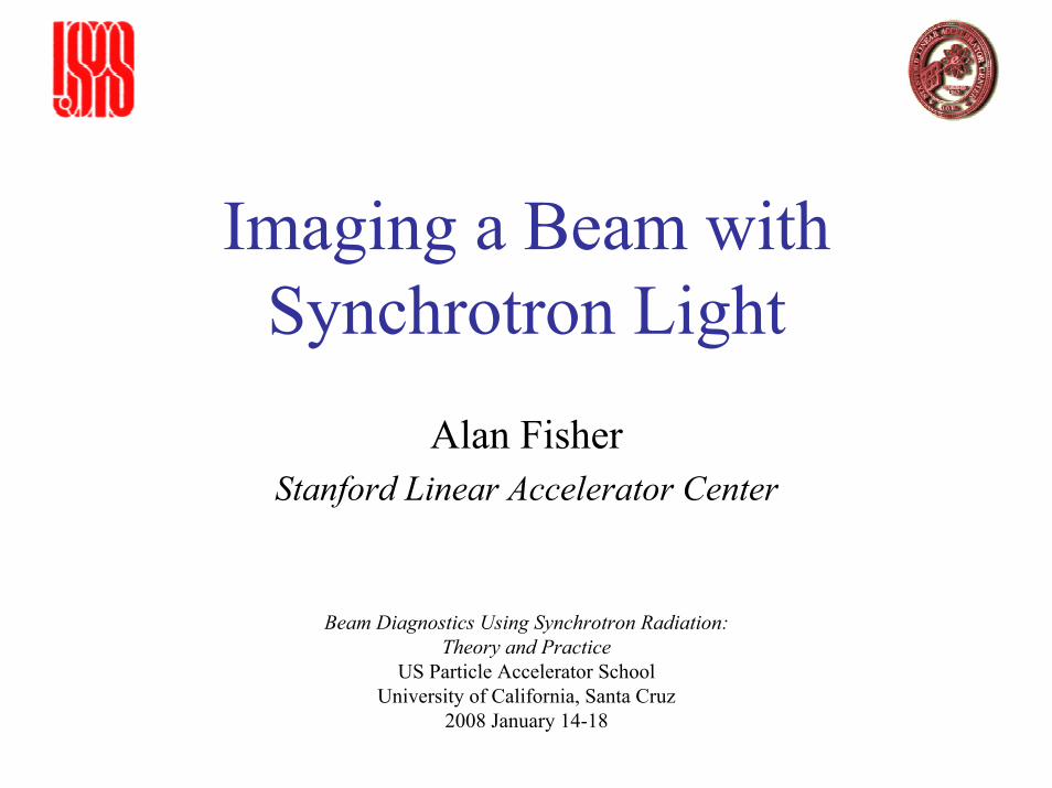
Power Radiated by the Beam
A later lecture derives the spectrum of synchrotron radiation from a highly relativistic electron. For now, a few results:
Power radiated while traveling along an orbit with radius of curvature ρ
where the “classical electron radius” is
The factor of γ 4 makes this power substantial. For example, 2 A of 9-GeV electrons in the PEP-II high-energy ring (HER) radiate
Ps IHER /ec = 6.8 kW/m
in the dipole magnets. The total power lost around the whole ring is2πρHER Ps IHER /ec = 7.0 MW
where ρHER = 165 m in the 192 arc dipoles.
4 3
2
23
e es
r m cP γρ
=2
152
0
2.818 10 m4e
e
erm cπε
−= = ×
2008-01-14 Fisher — Imaging with Synchrotron Light 3
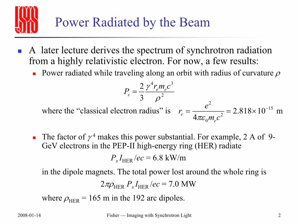
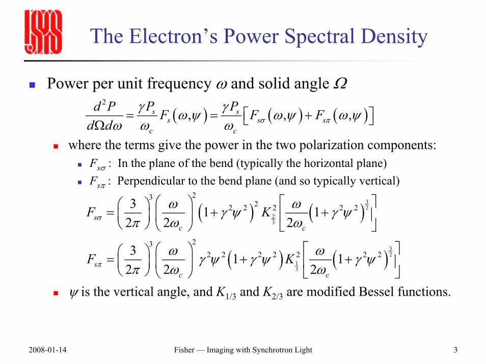
The Electron’s Power Spectral Density
Power per unit frequency ω and solid angle Ω
where the terms give the power in the two polarization components:Fsσ : In the plane of the bend (typically the horizontal plane)Fsπ : Perpendicular to the bend plane (and so typically vertical)
ψ is the vertical angle, and K1/3 and K2/3 are modified Bessel functions.
( ) ( )
( ) ( )
32
23
32
13
2322 2 2 2 2
232 2 2 2 2 2 2
3 1 12 2 2
3 1 12 2 2
sc c
sc c
F K
F K
σ
π
ω ωγ ψ γ ψπ ω ω
ω ωγ ψ γ ψ γ ψπ ω ω
⎛ ⎞ ⎡ ⎤⎛ ⎞= + +⎜ ⎟⎜ ⎟ ⎢ ⎥⎝ ⎠ ⎝ ⎠ ⎣ ⎦
⎛ ⎞ ⎡ ⎤⎛ ⎞= + +⎜ ⎟⎜ ⎟ ⎢ ⎥⎝ ⎠ ⎝ ⎠ ⎣ ⎦
( ) ( ) ( )2
, , ,s ss s s
c c
P Pd P F F Fd d σ π
γ γω ψ ω ψ ω ψω ω ω
⎡ ⎤= = +⎣ ⎦Ω
2008-01-14 Fisher — Imaging with Synchrotron Light 4
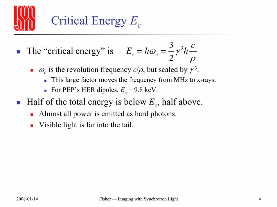
Critical Energy Ec
The “critical energy” is
ωc is the revolution frequency c/ρ, but scaled by γ 3.This large factor moves the frequency from MHz to x-rays.For PEP’s HER dipoles, Ec = 9.8 keV.
Half of the total energy is below Ec, half above.Almost all power is emitted as hard photons.Visible light is far into the tail.
332c c
cE ω γρ
= =
2008-01-14 Fisher — Imaging with Synchrotron Light 5
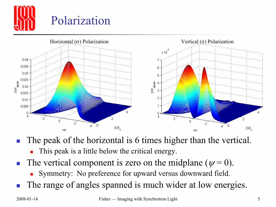
PolarizationHorizontal (σ) Polarization Vertical (π) Polarization
The peak of the horizontal is 6 times higher than the vertical.This peak is a little below the critical energy.
The vertical component is zero on the midplane (ψ = 0).Symmetry: No preference for upward versus downward field.
The range of angles spanned is much wider at low energies.
2008-01-14 Fisher — Imaging with Synchrotron Light 6
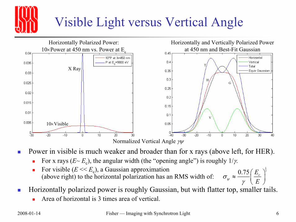
Visible Light versus Vertical Angle
Power in visible is much weaker and broader than for x rays (above left, for HER).For x rays (E~ Ec), the angular width (the “opening angle”) is roughly 1/γ.For visible (E << Ec), a Gaussian approximation(above right) to the horizontal polarization has an RMS width of:
Horizontally polarized power is roughly Gaussian, but with flatter top, smaller tails.Area of horizontal is 3 times area of vertical.
Horizontally Polarized Power:10×Power at 450 nm vs. Power at Ec
Horizontally and Vertically Polarized Power at 450 nm and Best-Fit Gaussian
130.75 cE
Eψσγ
⎛ ⎞≈ ⎜ ⎟⎝ ⎠
X Ray
10×Visible
H
T
G
V
Normalized Vertical Angle γψ
2008-01-14 Fisher — Imaging with Synchrotron Light 7
Peculiarities of Synchrotron-Light Imaging
Typical imaging situation:Object reflects unpolarized incident light in all directions.Lens catches some light from almost any angle.Most objects have more transverse extent than depth.
Synchrotron Light:The source of the light is the object’s own emission.Light is radiated only in the forward direction, tangent to the beam’s instantaneous circular path through a bend.
Vertically: The beam lights up narrow forward-directed cone.Horizontally: The beam paints a stripe of light along the midplane of the vacuum chamber as bends.Like a car rounding a bend in the dark with its bright headlights on.
Longitudinal profile is Gaussian at any instant.But over the exposure time, the source goes around the ring many times.We want to measure a glowing, curved string by imaging it from a tangent.
2008-01-14 Fisher — Imaging with Synchrotron Light 8
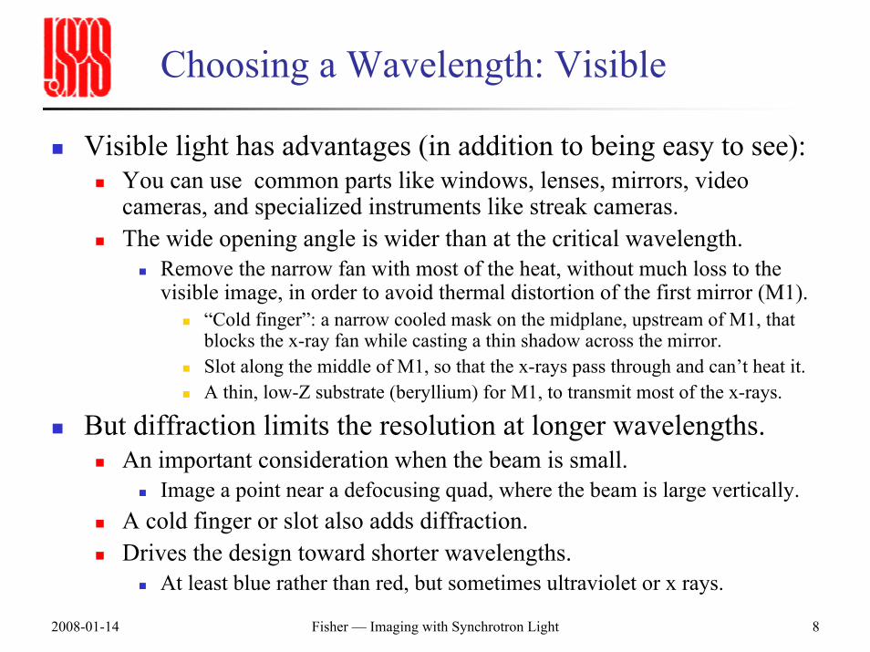
Choosing a Wavelength: Visible
Visible light has advantages (in addition to being easy to see):You can use common parts like windows, lenses, mirrors, video cameras, and specialized instruments like streak cameras.The wide opening angle is wider than at the critical wavelength.
Remove the narrow fan with most of the heat, without much loss to the visible image, in order to avoid thermal distortion of the first mirror (M1).
“Cold finger”: a narrow cooled mask on the midplane, upstream of M1, that blocks the x-ray fan while casting a thin shadow across the mirror.Slot along the middle of M1, so that the x-rays pass through and can’t heat it.A thin, low-Z substrate (beryllium) for M1, to transmit most of the x-rays.
But diffraction limits the resolution at longer wavelengths.An important consideration when the beam is small.
Image a point near a defocusing quad, where the beam is large vertically.A cold finger or slot also adds diffraction.Drives the design toward shorter wavelengths.
At least blue rather than red, but sometimes ultraviolet or x rays.
2008-01-14 Fisher — Imaging with Synchrotron Light 9
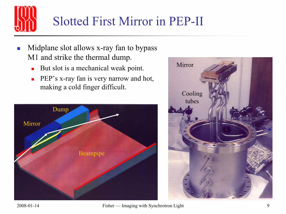
Slotted First Mirror in PEP-II
Midplane slot allows x-ray fan to bypass M1 and strike the thermal dump.
But slot is a mechanical weak point.PEP’s x-ray fan is very narrow and hot, making a cold finger difficult.
Mirror
Cooling tubes
Mirror
Dump
Beampipe
2008-01-14 Fisher — Imaging with Synchrotron Light 10
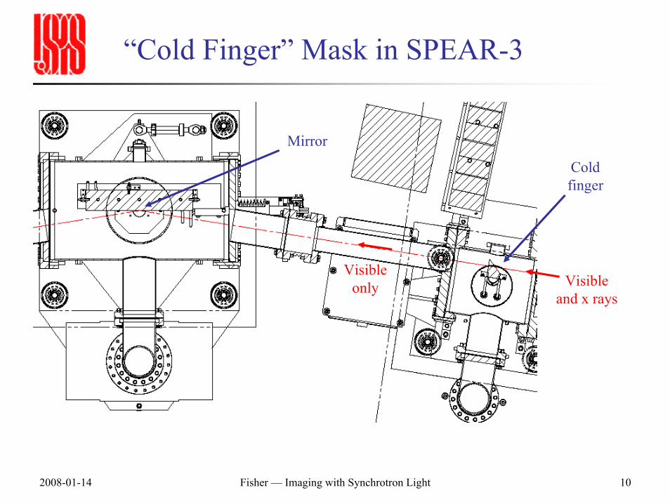
“Cold Finger” Mask in SPEAR-3
Cold finger
Mirror
Visibleonly Visible
and x rays
2008-01-14 Fisher — Imaging with Synchrotron Light 11
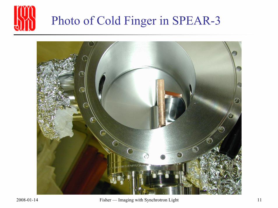
Photo of Cold Finger in SPEAR-3
2008-01-14 Fisher — Imaging with Synchrotron Light 12
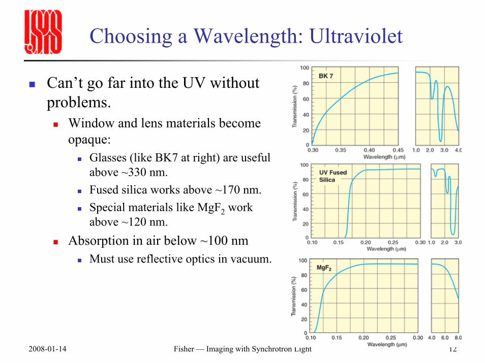
Choosing a Wavelength: Ultraviolet
Can’t go far into the UV without problems.
Window and lens materials become opaque:
Glasses (like BK7 at right) are useful above ~330 nm.Fused silica works above ~170 nm.Special materials like MgF2 work above ~120 nm.
Absorption in air below ~100 nmMust use reflective optics in vacuum.
2008-01-14 Fisher — Imaging with Synchrotron Light 13
Choosing a Wavelength: X Rays
The good news: Most of the beam’s emission is in the x-ray range.The bad news: How do you form an image?
You can use a simple pinhole camera.But this throws out most of the light.Must absorb this power before the pinhole, or it will get too hot.
Other imaging optics are difficult:Grazing-incidence opticsZone plates
2008-01-14 Fisher — Imaging with Synchrotron Light 14
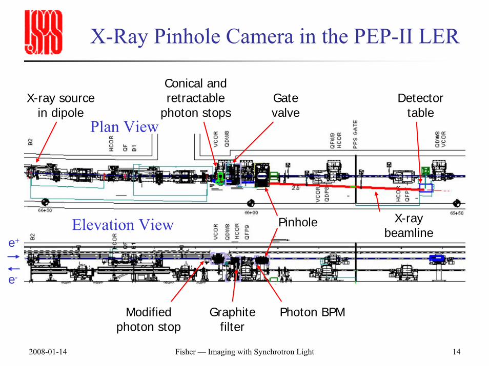
X-Ray Pinhole Camera in the PEP-II LER
X-ray source in dipole
Detector table
Conical and retractable
photon stops
Pinhole
Gate valve
X-ray beamline
e-
e+
Plan View
Elevation View
Graphite filter
Photon BPMModified photon stop
2008-01-14 Fisher — Imaging with Synchrotron Light 15
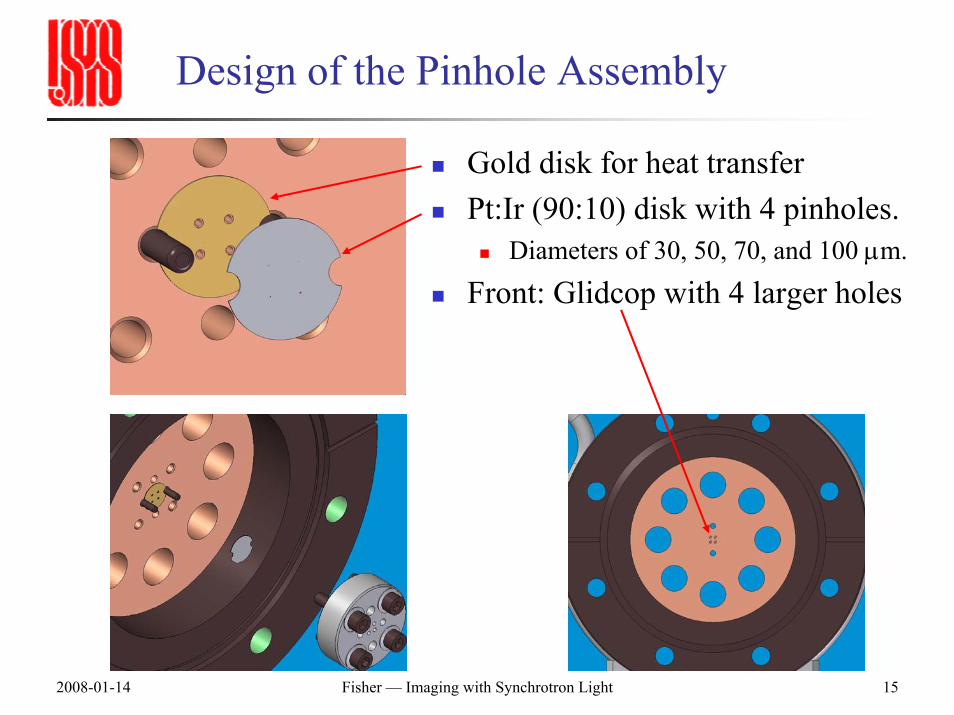
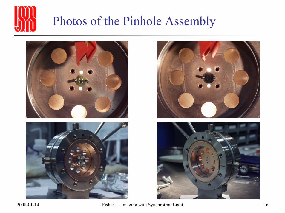
Design of the Pinhole Assembly
Gold disk for heat transferPt:Ir (90:10) disk with 4 pinholes.
Diameters of 30, 50, 70, and 100 µm.
Front: Glidcop with 4 larger holes
2008-01-14 Fisher — Imaging with Synchrotron Light 16
Photos of the Pinhole Assembly
2008-01-14 Fisher — Imaging with Synchrotron Light 17
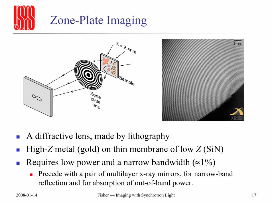
Zone-Plate Imaging
A diffractive lens, made by lithographyHigh-Z metal (gold) on thin membrane of low Z (SiN)Requires low power and a narrow bandwidth (≈1%)
Precede with a pair of multilayer x-ray mirrors, for narrow-band reflection and for absorption of out-of-band power.
2008-01-14 Fisher — Imaging with Synchrotron Light 18
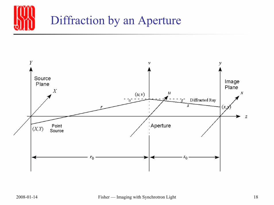
Diffraction by an Aperture
2008-01-14 Fisher — Imaging with Synchrotron Light 19
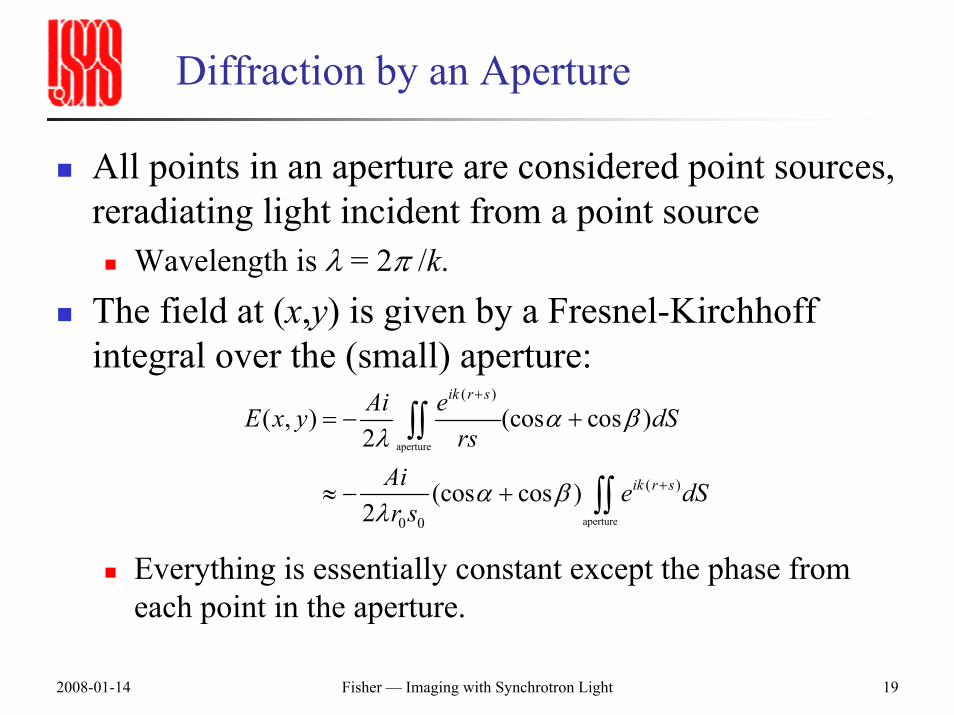
Diffraction by an Aperture
All points in an aperture are considered point sources, reradiating light incident from a point source
Wavelength is λ = 2π /k.The field at (x,y) is given by a Fresnel-Kirchhoff integral over the (small) aperture:
Everything is essentially constant except the phase from each point in the aperture.
aperture
aperture
( )
( )
0 0
( , ) (cos cos )2
(cos cos )2
ik r s
ik r s
Ai eE x y dSrs
Ai e dSr s
α βλ
α βλ
+
+
= − +
≈ − +
∫∫
∫∫
2008-01-14 Fisher — Imaging with Synchrotron Light 20
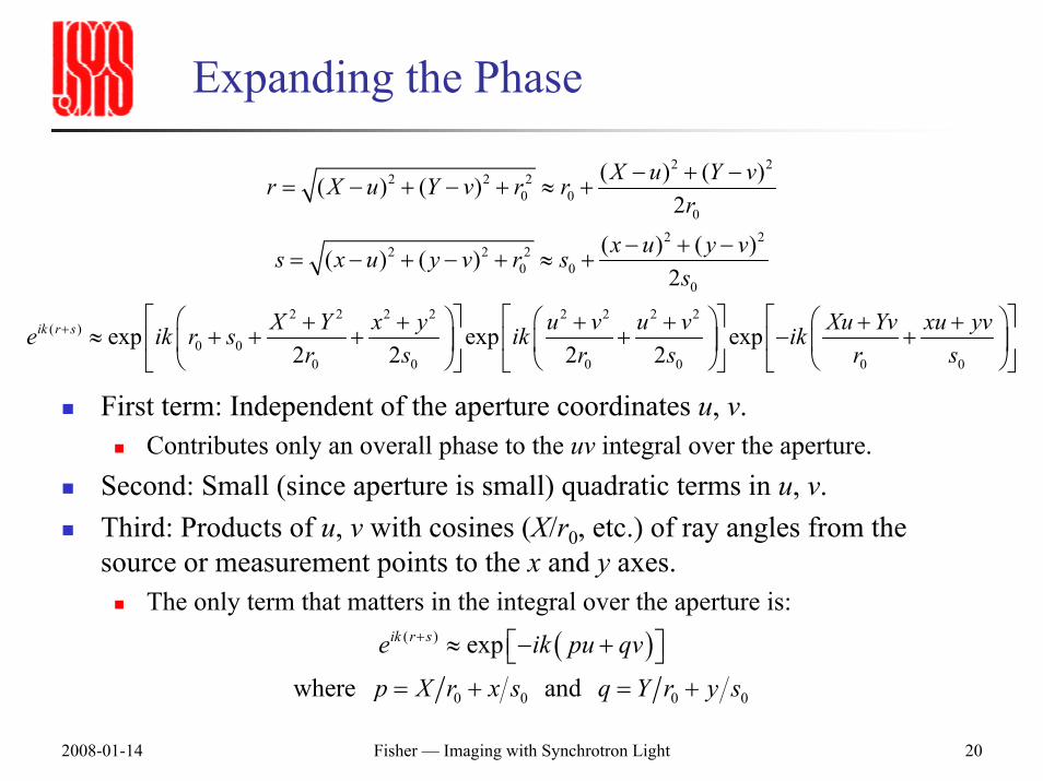
Expanding the Phase
2 22 2 2
0 00
2 22 2 2
0 00
2 2 2 2 2 2 2 2( )
0 00 0 0 0 0 0
( ) ( )( ) ( )2
( ) ( )( ) ( )2
exp exp exp2 2 2 2
ik r s
X u Y vr X u Y v r rr
x u y vs x u y v r ss
X Y x y u v u v Xu Yv xu yve ik r s ik ikr s r s r s
+
− + −= − + − + ≈ +
− + −= − + − + ≈ +
⎡ ⎤ ⎡ ⎤ ⎡ ⎤⎛ ⎞ ⎛ ⎞ ⎛ ⎞+ + + + + +≈ + + + + − +⎢ ⎥ ⎢ ⎥ ⎢ ⎥⎜ ⎟ ⎜ ⎟ ⎜ ⎟
⎝ ⎠ ⎝ ⎠ ⎝ ⎠⎣ ⎦ ⎣ ⎦ ⎣ ⎦
First term: Independent of the aperture coordinates u, v.Contributes only an overall phase to the uv integral over the aperture.
Second: Small (since aperture is small) quadratic terms in u, v.Third: Products of u, v with cosines (X/r0, etc.) of ray angles from the source or measurement points to the x and y axes.
The only term that matters in the integral over the aperture is:
( )( )
0 0 0 0
exp
where and
ik r se ik pu qv
p X r x s q Y r y s
+ ⎡ ⎤≈ − +⎣ ⎦= + = +
2008-01-14 Fisher — Imaging with Synchrotron Light 21
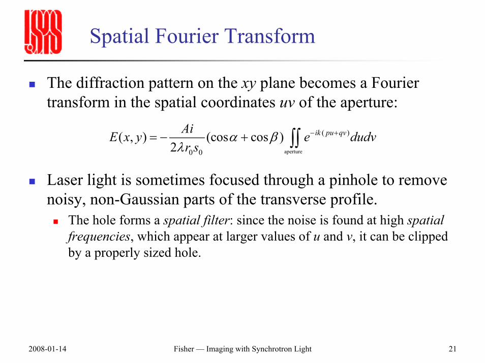
Spatial Fourier Transform
The diffraction pattern on the xy plane becomes a Fourier transform in the spatial coordinates uv of the aperture:
Laser light is sometimes focused through a pinhole to remove noisy, non-Gaussian parts of the transverse profile.
The hole forms a spatial filter: since the noise is found at high spatial frequencies, which appear at larger values of u and v, it can be clipped by a properly sized hole.
aperture
( )
0 0
( , ) (cos cos )2
ik pu qvAiE x y e dudvr s
α βλ
− += − + ∫∫
2008-01-14 Fisher — Imaging with Synchrotron Light 22
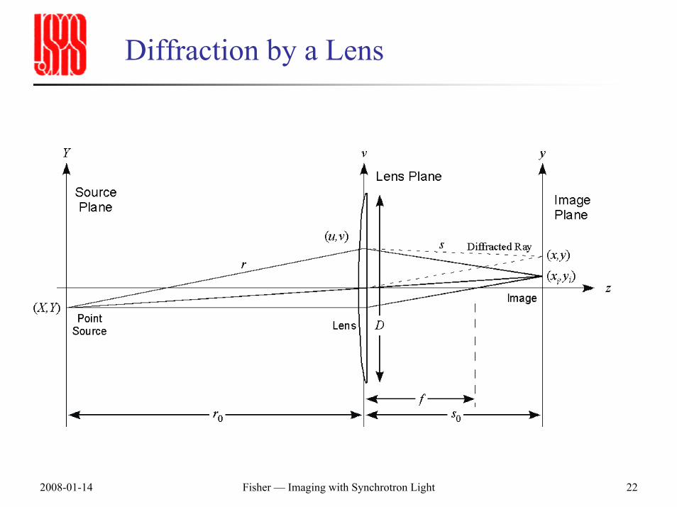
Diffraction by a Lens
2008-01-14 Fisher — Imaging with Synchrotron Light 23
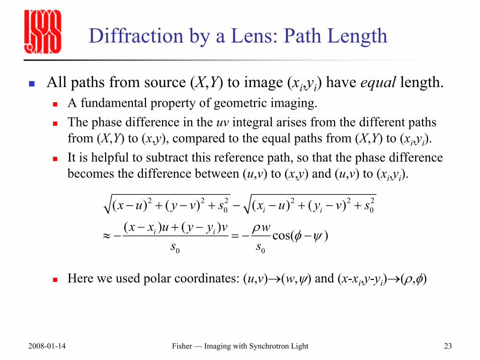
Diffraction by a Lens: Path Length
All paths from source (X,Y) to image (xi,yi) have equal length.A fundamental property of geometric imaging.The phase difference in the uv integral arises from the different paths from (X,Y) to (x,y), compared to the equal paths from (X,Y) to (xi,yi).It is helpful to subtract this reference path, so that the phase difference becomes the difference between (u,v) to (x,y) and (u,v) to (xi,yi).
Here we used polar coordinates: (u,v)→(w,ψ) and (x-xi,y-yi)→(ρ,φ)
2 2 2 2 2 20 0
0 0
( ) ( ) ( ) ( )( ) ( ) cos( )
i i
i i
x u y v s x u y v sx x u y y v w
s sρ φ ψ
− + − + − − + − +
− + −≈ − = − −
2008-01-14 Fisher — Imaging with Synchrotron Light 24
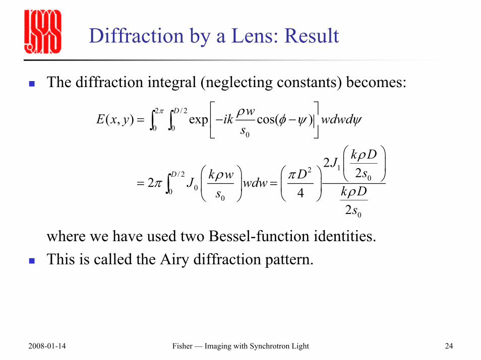
Diffraction by a Lens: Result
The diffraction integral (neglecting constants) becomes:
where we have used two Bessel-function identities.This is called the Airy diffraction pattern.
2 / 2
0 00
12/ 2 000
0
0
( , ) exp cos( )
22
24
2
D
D
wE x y ik wdwds
k DJsk w DJ wdw k Ds
s
π ρ φ ψ ψ
ρρ ππ ρ
⎡ ⎤= − −⎢ ⎥
⎣ ⎦⎛ ⎞⎜ ⎟⎛ ⎞ ⎛ ⎞ ⎝ ⎠= =⎜ ⎟ ⎜ ⎟
⎝ ⎠⎝ ⎠
∫ ∫
∫
2008-01-14 Fisher — Imaging with Synchrotron Light 25
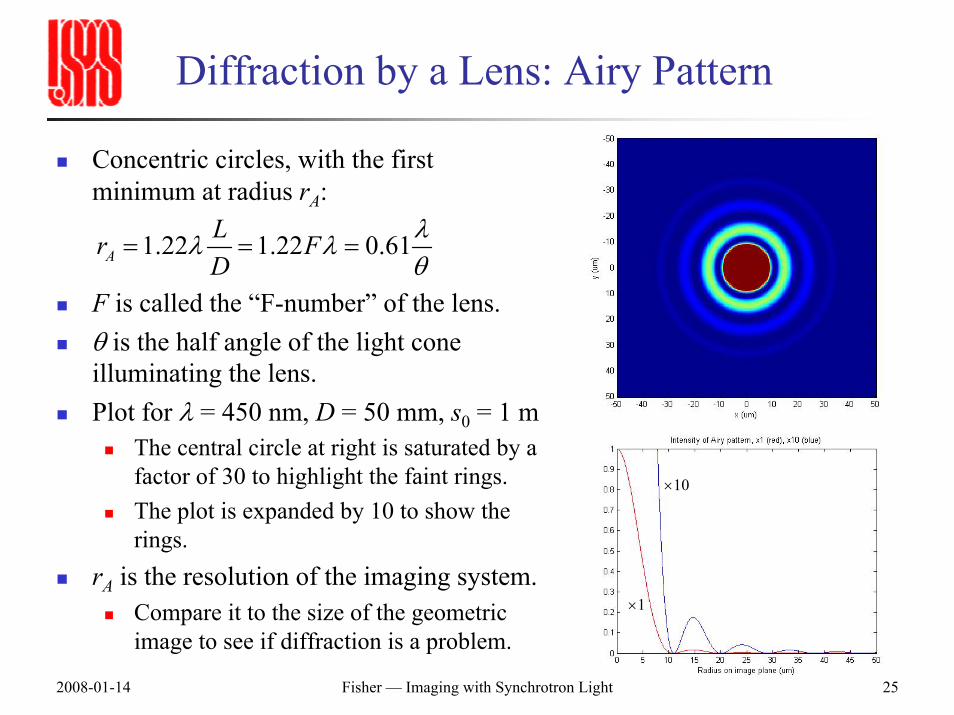
Diffraction by a Lens: Airy Pattern
×10
×1
Concentric circles, with the first minimum at radius rA:
F is called the “F-number” of the lens.θ is the half angle of the light cone illuminating the lens.Plot for λ = 450 nm, D = 50 mm, s0 = 1 m
The central circle at right is saturated by a factor of 30 to highlight the faint rings.The plot is expanded by 10 to show the rings.
rA is the resolution of the imaging system.Compare it to the size of the geometric image to see if diffraction is a problem.
1.22 1.22 0.61ALr FD
λλ λθ
= = =
2008-01-14 Fisher — Imaging with Synchrotron Light 26
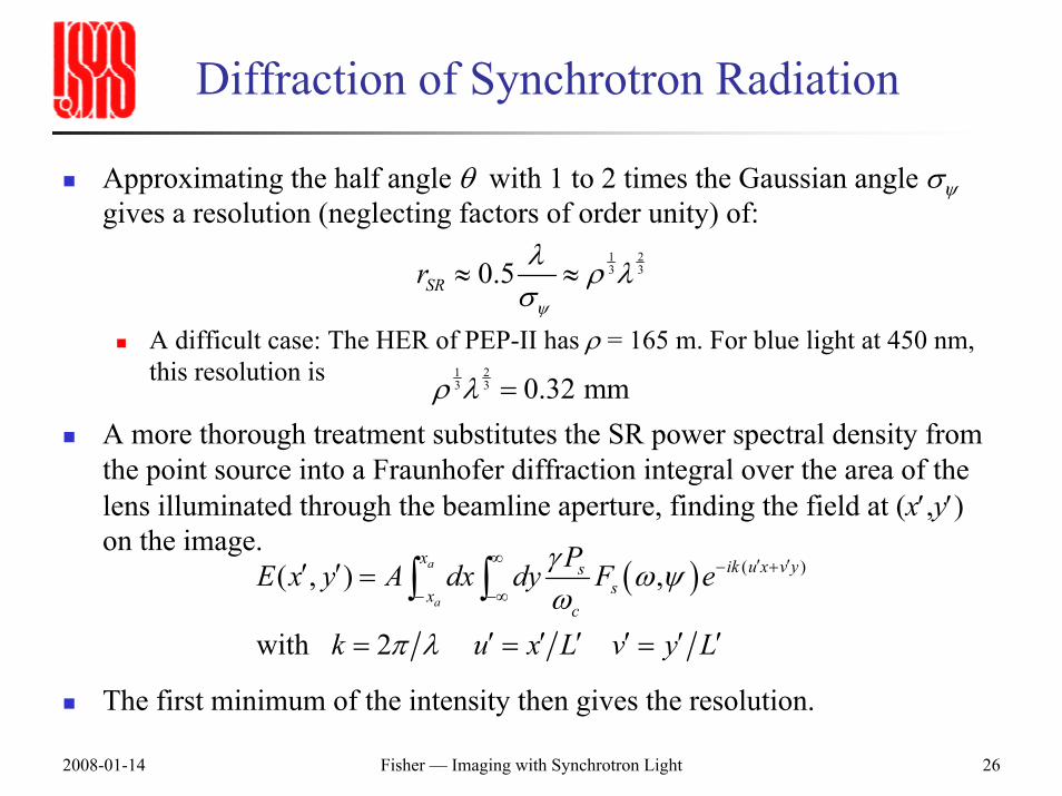
Diffraction of Synchrotron Radiation
Approximating the half angle θ with 1 to 2 times the Gaussian angle σψgives a resolution (neglecting factors of order unity) of:
A difficult case: The HER of PEP-II has ρ = 165 m. For blue light at 450 nm, this resolution is
A more thorough treatment substitutes the SR power spectral density from the point source into a Fraunhofer diffraction integral over the area of the lens illuminated through the beamline aperture, finding the field at (x′,y′) on the image.
The first minimum of the intensity then gives the resolution.
1 23 30.5SRr
ψ
λ ρ λσ
≈ ≈
( ) ( )( , ) ,
with 2
a
a
x ik u x v yssx
c
PE x y A dx dy F e
k u x L v y L
γ ω ψω
π λ
∞ ′ ′− +
− −∞′ ′ =
′ ′ ′ ′ ′ ′= = =
∫ ∫
1 23 3 0.32 mmρ λ =
2008-01-14 Fisher — Imaging with Synchrotron Light 27
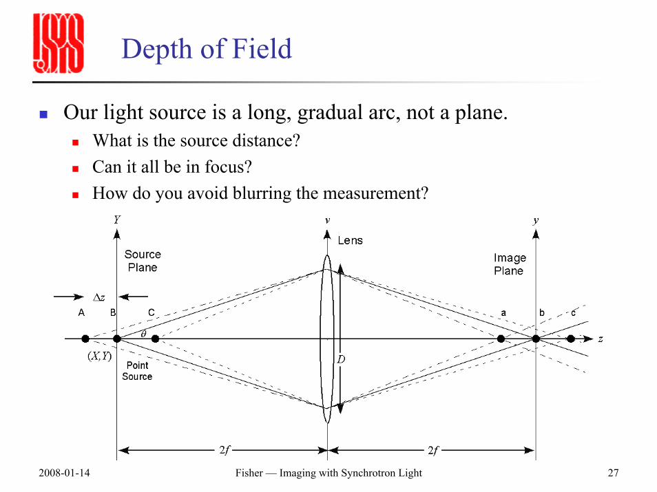
Depth of Field
Our light source is a long, gradual arc, not a plane.What is the source distance?Can it all be in focus?How do you avoid blurring the measurement?
2008-01-14 Fisher — Imaging with Synchrotron Light 28
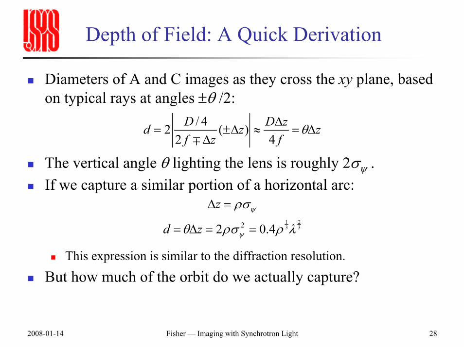
Depth of Field: A Quick Derivation
Diameters of A and C images as they cross the xy plane, based on typical rays at angles ±θ /2:
The vertical angle θ lighting the lens is roughly 2σψ .If we capture a similar portion of a horizontal arc:
This expression is similar to the diffraction resolution.
But how much of the orbit do we actually capture?
/ 42 ( )2 4
D D zd z zf z f
θ∆= ±∆ ≈ = ∆
∆∓
1 23 322 0.4
z
d z
ψ
ψ
ρσ
θ ρσ ρ λ
∆ =
= ∆ = =
2008-01-14 Fisher — Imaging with Synchrotron Light 29
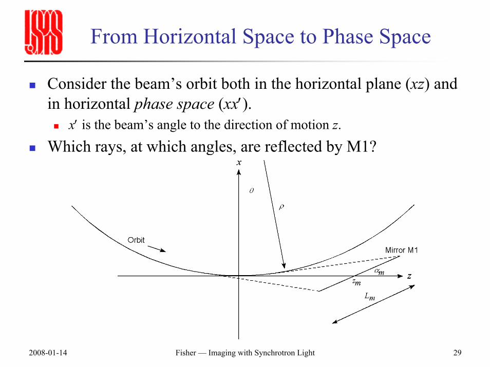
From Horizontal Space to Phase Space
Consider the beam’s orbit both in the horizontal plane (xz) and in horizontal phase space (xx′).
x′ is the beam’s angle to the direction of motion z.
Which rays, at which angles, are reflected by M1?
2008-01-14 Fisher — Imaging with Synchrotron Light 30
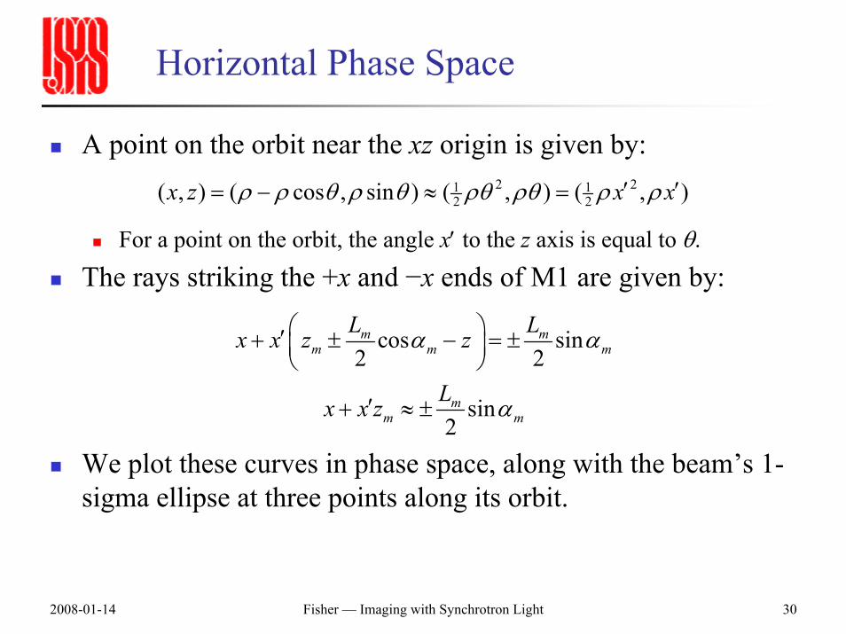
Horizontal Phase Space
A point on the orbit near the xz origin is given by:
For a point on the orbit, the angle x′ to the z axis is equal to θ.
The rays striking the +x and −x ends of M1 are given by:
We plot these curves in phase space, along with the beam’s 1-sigma ellipse at three points along its orbit.
2 21 12 2( , ) ( cos , sin ) ( , ) ( , )x z x xρ ρ θ ρ θ ρθ ρθ ρ ρ′ ′= − ≈ =
cos sin2 2
sin2
m mm m m
mm m
L Lx x z z
Lx x z
α α
α
⎛ ⎞′+ ± − = ±⎜ ⎟⎝ ⎠
′+ ≈ ±
2008-01-14 Fisher — Imaging with Synchrotron Light 31
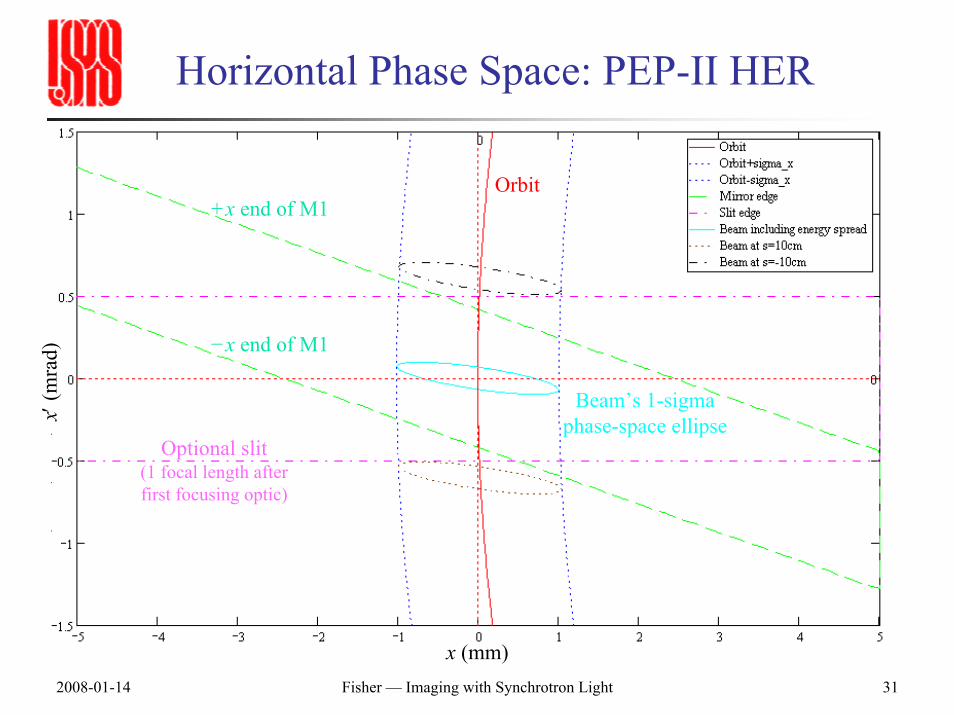
Horizontal Phase Space: PEP-II HER
x (mm)
x′(m
rad)
+x end of M1
−x end of M1
Orbit
Optional slit(1 focal length after first focusing optic)
Beam’s 1-sigma phase-space ellipse
2008-01-14 Fisher — Imaging with Synchrotron Light 32
Vertical Phase Space
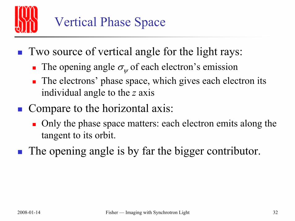
Two source of vertical angle for the light rays:The opening angle σψ of each electron’s emissionThe electrons’ phase space, which gives each electron its individual angle to the z axis
Compare to the horizontal axis:Only the phase space matters: each electron emits along the tangent to its orbit.
The opening angle is by far the bigger contributor.
2008-01-14 Fisher — Imaging with Synchrotron Light 33
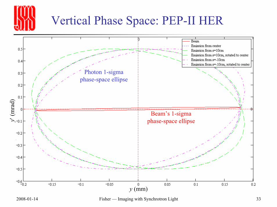
Vertical Phase Space: PEP-II HER
y (mm)
y′(m
rad)
Beam’s 1-sigma phase-space ellipse
Photon 1-sigma phase-space ellipse
2008-01-14 Fisher — Imaging with Synchrotron Light 34
Photon Emittance (Brightness)
Accelerator people know that Liouville’s theorem conserves the emittance of a beam in a transport line.
The phase-space ellipse changes shape, but not area.At each waist, the size-angle product σxσx′ is constant.
(But in a ring, dissipation by synchrotron radiation allows damping that “cheats” Liouville.)
Light in an optical transport line has an emittance too.At each image, the product of size and opening angle (light-cone angle) is constant.
Magnification makes the image bigger, but the angle smaller.
The area of the light’s phase-space ellipse—the brightness of the source—is conserved.
2008-01-14 Fisher — Imaging with Synchrotron Light 35
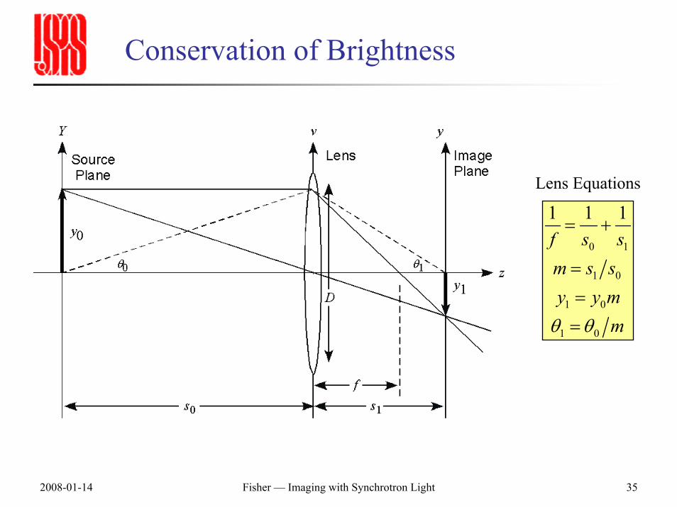
Conservation of Brightness
Lens Equations
0 1
1 0
1 0
1 0
1 1 1f s sm s sy y m
mθ θ
= +
=
==
2008-01-14 Fisher — Imaging with Synchrotron Light 36
Minimum Photon Emittance
The minimum emittance for a light beam is that of the lowest-order Gaussian mode (TEM00) of a laser.
ω is the beam radius.In the usual definition (where ω is not the one-sigma value):
The electric field follows E(r) = E0exp(−r2/ω2)The intensity (power) is the square: I(r) = I0exp(− 2r2/ω2)
ω0 is the radius at the waist (the focus).This size is nonzero due to diffraction.
zR = πω02/λ is the Rayleigh range.
Characteristic distance for beam expansion due to diffraction.The expansion is given by ω2(z) = ω0
2(1+z2/zR2)
The angle (for z >> zR) is θ = ω/z = ω0/zR = λ/πω0
The product of waist size and angle is then ω0θ = λ/πOne-sigma values for the size and angle of I give an emittance of λ/4π
2008-01-14 Fisher — Imaging with Synchrotron Light 37
Constraints on the Beamline
Distance to the first mirrorFlush with the beampipe wall?Far down a synchrotron-light beamline?Ports and M1 itself introduce wakefields and impedance.The heat load on M1 is reduced by distance.
Distance to the imaging opticsIn a hutch: adds distance to get outside shieldingIn the tunnel: not accessible, but often necessary for large colliders.
Size and location of the optical table.
2008-01-14 Fisher — Imaging with Synchrotron Light 38
Constraints on the Optical Design
Choose a source point with a large y size, to lessen effect of diffraction.Magnification: Transform expected beam size to a reasonable size on the camera.
6σ < camera size < 10σ : Uses many pixels; keeps the image and the tails on the camera; allows for orbit changes.Needs at least two imaging stages: Since the optics are generally far from the source, the first focusing element strongly demagnifies.
Optics: Use standard components whenever possible.For example, adjust the design to use off-the-shelf focal lengths from the catalog of a high-quality vendor.Use a color filter to avoid dispersion (or use reflective optics).Correct the focal length (specified at one wavelength) for your color.
2008-01-14 Fisher — Imaging with Synchrotron Light 39
Basic Design Spreadsheet
You can iterate a lot of the basic design in a simple spreadsheet.
Enter the fixed distances.Specify the desired magnifications.Solve the lens equations, one stage at a time, to find lenses giving the ideal magnifications.Change the lenses to catalog focal lengths.Correct their focal lengths (using the formula for each material as found in many catalogs).Adjust magnifications and distances.