Embed Size (px)
Citation preview
High Brightness Electron Injectors for Light Sources - January 14-18 2007
Lecture 7D.H. Dowell, S. Lidia, J.F. Schmerge
Longitudinal and Transverse Matching
Lecture 7:Matching the Beam to the Linac
S. Lidia, LBNL
High Brightness Electron Injectors for Light Sources - January 14-18 2007
Lecture 7D.H. Dowell, S. Lidia, J.F. Schmerge
Longitudinal and Transverse Matching
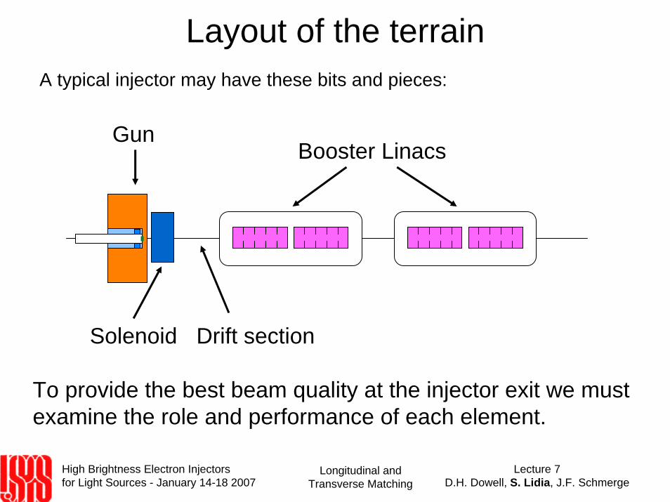
Layout of the terrainA typical injector may have these bits and pieces:
To provide the best beam quality at the injector exit we must examine the role and performance of each element.
Gun
Solenoid
Booster Linacs
Drift section
High Brightness Electron Injectors for Light Sources - January 14-18 2007
Lecture 7D.H. Dowell, S. Lidia, J.F. Schmerge
Longitudinal and Transverse Matching
Review of Emittance Compensation• As we discussed previously (linear) emittance compensation is a
strategy for reducing the effects of slice-dependent transverse phase space rotations and offsets due to – Beam envelope mismatch, envelope modulations– RF focusing/defocusing/transverse kicks– Beam current and energy modulations
• The beam leaves the cathode with it’s ‘thermal’ emittance value.• The beam exits the gun and picks up time-dependent transverse
kicks and defocusing impulses.• An ‘emittance compensating’ solenoid can reverse the divergences
of the slice trajectories, allowing them to re-overlap.• Acceleration decreases the radial oscillation wavenumber and
amplitude– eventually halting the emittance oscillation.
High Brightness Electron Injectors for Light Sources - January 14-18 2007
Lecture 7D.H. Dowell, S. Lidia, J.F. Schmerge
Longitudinal and Transverse Matching
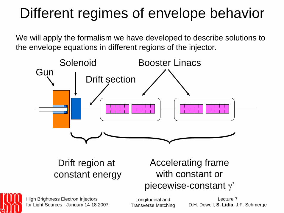
Different regimes of envelope behavior
GunSolenoid Booster Linacs
Drift section
Drift region at constant energy
Accelerating frame with constant or
piecewise-constant γ’
We will apply the formalism we have developed to describe solutions to the envelope equations in different regions of the injector.

High Brightness Electron Injectors for Light Sources - January 14-18 2007
Lecture 7D.H. Dowell, S. Lidia, J.F. Schmerge
Longitudinal and Transverse Matching
RMS Envelope Equation
σ r′′ +
′ γ γ
σ r′ + keff
2σ r −εeff
2
σ r3 −
Kσ r
= 0
We recall the envelope equation
keff2 =
′ ′ γ 2γ
+ kRF2 + kL
2 kL2 =
eBz
2γmc⎛
⎝ ⎜
⎞
⎠ ⎟
2
kRF2 =
12
eEγmc 2
⎛
⎝ ⎜
⎞
⎠ ⎟
2
η φ( ) ≈12
′ γ γ
⎛
⎝ ⎜
⎞
⎠ ⎟
2
εeff2 = 4εr
2 +pθ
2
γ 2β 2m2c 2
= 4εr2 +
e2 Bz,cathodeσ r,cathode( )2
γ 2β 2m2c 2
High Brightness Electron Injectors for Light Sources - January 14-18 2007
Lecture 7D.H. Dowell, S. Lidia, J.F. Schmerge
Longitudinal and Transverse Matching
Initial conditions from the gun• Gun gradient• Beam energy• Bunch charge, peak current• Bunch length, longitudinal distribution• Energy chirp• Slice energy spread• RMS spot size (cathode, exit iris)• Slice envelope divergence• Transverse emittance, transverse distribution• Thermal emittance
• Correlated emittance contributions– Need to consider the beam slice-by-slice to distinguish correlated from
uncorrelated effects.– Even that may not be enough for all high brightness applications . . .
High Brightness Electron Injectors for Light Sources - January 14-18 2007
Lecture 7D.H. Dowell, S. Lidia, J.F. Schmerge
Longitudinal and Transverse Matching
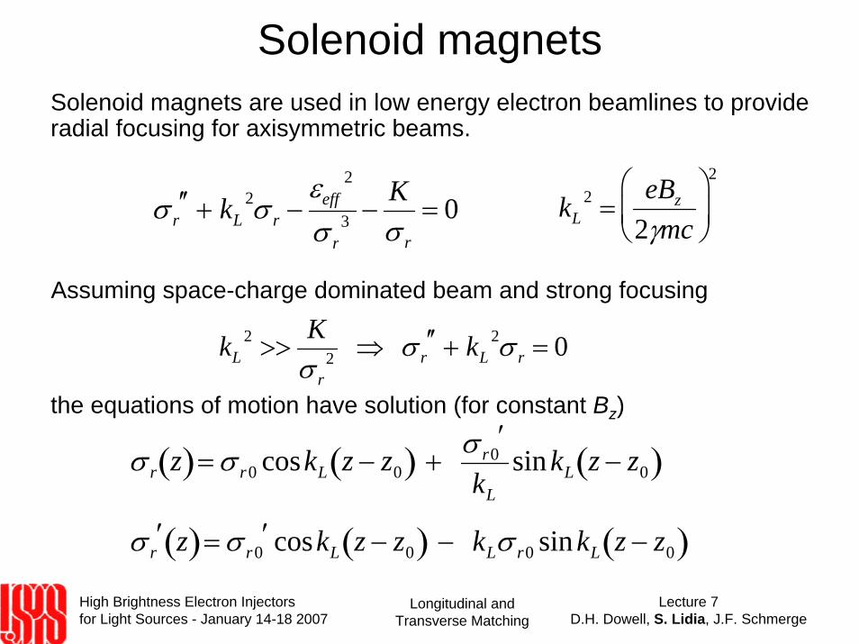
Solenoid magnetsSolenoid magnets are used in low energy electron beamlines to provide radial focusing for axisymmetric beams.
σ r′′ + kL
2σ r −εeff
2
σ r3 −
Kσ r
= 0
Assuming space-charge dominated beam and strong focusing
kL2 >>
Kσ r
2 ⇒ σ r′′ + kL
2σ r = 0
kL2 =
eBz
2γmc⎛
⎝ ⎜
⎞
⎠ ⎟
2
the equations of motion have solution (for constant Bz)
σ r z( )= σ r0 coskL z − z0( ) + σ r0′
kL
sin kL z − z0( )
σ r′ z( )= σ r0
′ coskL z − z0( ) − kLσ r0 sinkL z − z0( )
High Brightness Electron Injectors for Light Sources - January 14-18 2007
Lecture 7D.H. Dowell, S. Lidia, J.F. Schmerge
Longitudinal and Transverse Matching
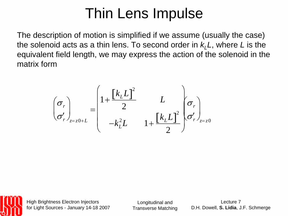
Thin Lens ImpulseThe description of motion is simplified if we assume (usually the case) the solenoid acts as a thin lens. To second order in kLL, where L is the equivalent field length, we may express the action of the solenoid in the matrix form
σ r
′ σ r
⎛
⎝ ⎜
⎞
⎠ ⎟
z= z0+L
=1+
kLL[ ]2
2L
−kL2L 1+
kLL[ ]2
2
⎛
⎝
⎜ ⎜ ⎜ ⎜
⎞
⎠
⎟ ⎟ ⎟ ⎟
σ r
′ σ r
⎛
⎝ ⎜
⎞
⎠ ⎟
z= z0
High Brightness Electron Injectors for Light Sources - January 14-18 2007
Lecture 7D.H. Dowell, S. Lidia, J.F. Schmerge
Longitudinal and Transverse Matching
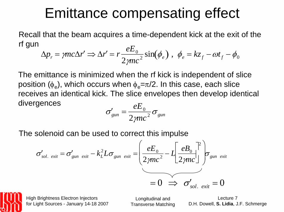
Emittance compensating effectRecall that the beam acquires a time-dependent kick at the exit of the rf gun
Δpr = γmcΔ ′ r ⇒ Δ ′ r = r eE0
2γmc 2 sin φe( ) , φe = kz f −ωt f − φ0
The emittance is minimized when the rf kick is independent of slice position (φe), which occurs when φe=π/2. In this case, each slice receives an identical kick. The slice envelopes then develop identical divergences
′ σ gun =eE0
2γmc 2 σ gun
The solenoid can be used to correct this impulse
′ σ sol. exit = ′ σ gun exit − kL2Lσ gun exit =
eE0
2γmc 2 − L eB0
2γmc⎡
⎣ ⎢
⎤
⎦ ⎥
2⎛
⎝ ⎜ ⎜
⎞
⎠ ⎟ ⎟ σ gun exit
= 0 ⇒ ′ σ sol. exit = 0
High Brightness Electron Injectors for Light Sources - January 14-18 2007
Lecture 7D.H. Dowell, S. Lidia, J.F. Schmerge
Longitudinal and Transverse Matching
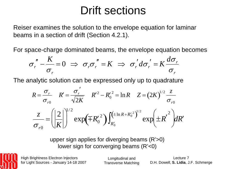
Drift sectionsReiser examines the solution to the envelope equation for laminar beams in a section of drift (Section 4.2.1).
For space-charge dominated beams, the envelope equation becomes
The analytic solution can be expressed only up to quadrature
σ r′′ −
Kσ r
= 0 ⇒ σ rσ r′′ = K ⇒ σ r
′dσ r′ = K dσ r
σ r
zσ r0
=2K
⎛
⎝ ⎜
⎞
⎠ ⎟
1/ 2
exp m ′ R 02( ) exp
′ R 0
± ln R + ′ R 02( )1/2
∫ ±R′2⎛
⎝ ⎜
⎞ ⎠ ⎟ d ′ R
R =σ r
σ r0
′ R =σ r
′
2K ′ R 2 − ′ R 0
2 = lnR Z = 2K( )1/ 2 zσ r0
upper sign applies for diverging beams (R’>0)lower sign for converging beams (R’<0)
High Brightness Electron Injectors for Light Sources - January 14-18 2007
Lecture 7D.H. Dowell, S. Lidia, J.F. Schmerge
Longitudinal and Transverse Matching
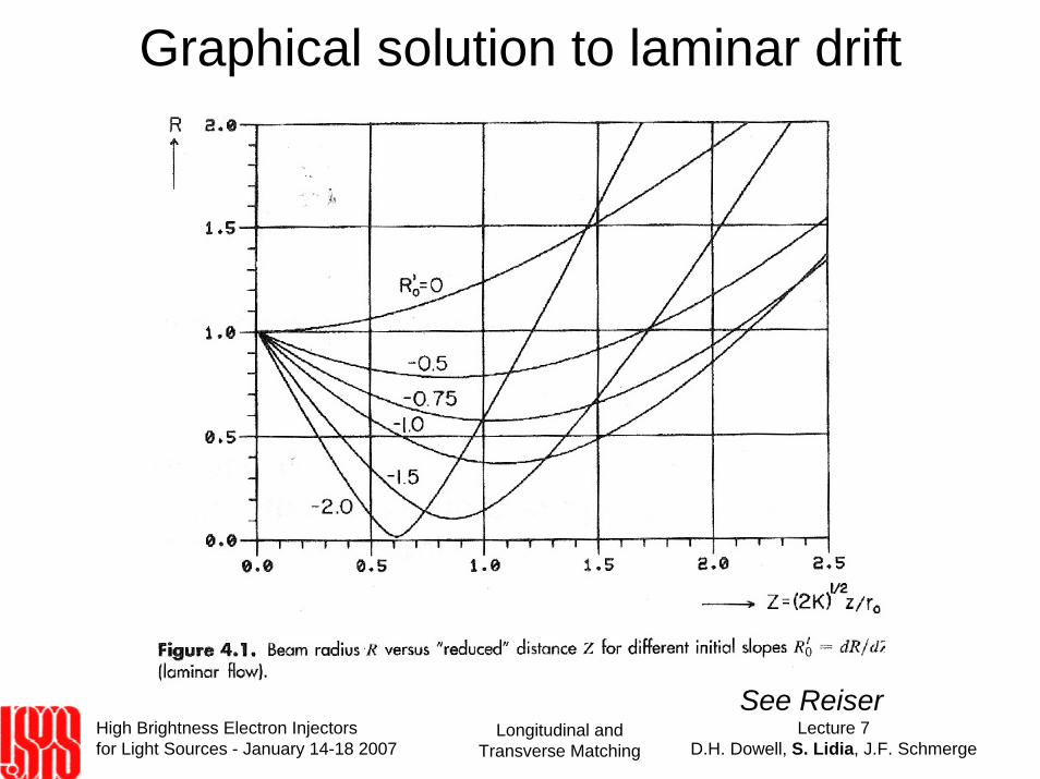
Graphical solution to laminar drift
See Reiser
High Brightness Electron Injectors for Light Sources - January 14-18 2007
Lecture 7D.H. Dowell, S. Lidia, J.F. Schmerge
Longitudinal and Transverse Matching
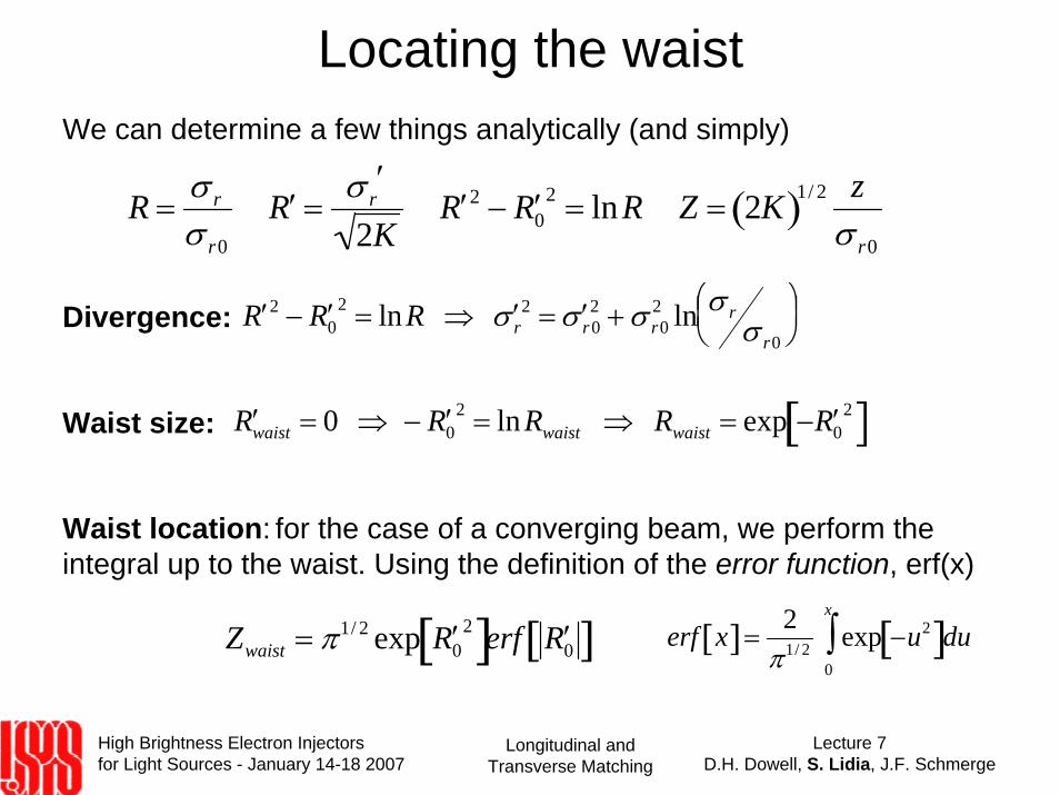
Locating the waistWe can determine a few things analytically (and simply)
Waist location: for the case of a converging beam, we perform the integral up to the waist. Using the definition of the error function, erf(x)
R =σ r
σ r0
′ R =σ r
′
2K ′ R 2 − ′ R 0
2 = lnR Z = 2K( )1/ 2 zσ r0
Divergence: ′ R 2 − ′ R 02 = lnR ⇒ ′ σ r
2 = ′ σ r02 + σ r0
2 ln σ rσ r0
⎛ ⎝ ⎜ ⎞
⎠ ⎟
Waist size: ′ R waist = 0 ⇒ − ′ R 02 = lnRwaist ⇒ Rwaist = exp − ′ R 0
2[ ]
Zwaist = π1/ 2 exp ′ R 02[ ]erf ′ R 0[ ] erf x[ ]=
2π1/ 2 exp −u2[ ]du
0
x
∫
High Brightness Electron Injectors for Light Sources - January 14-18 2007
Lecture 7D.H. Dowell, S. Lidia, J.F. Schmerge
Longitudinal and Transverse Matching
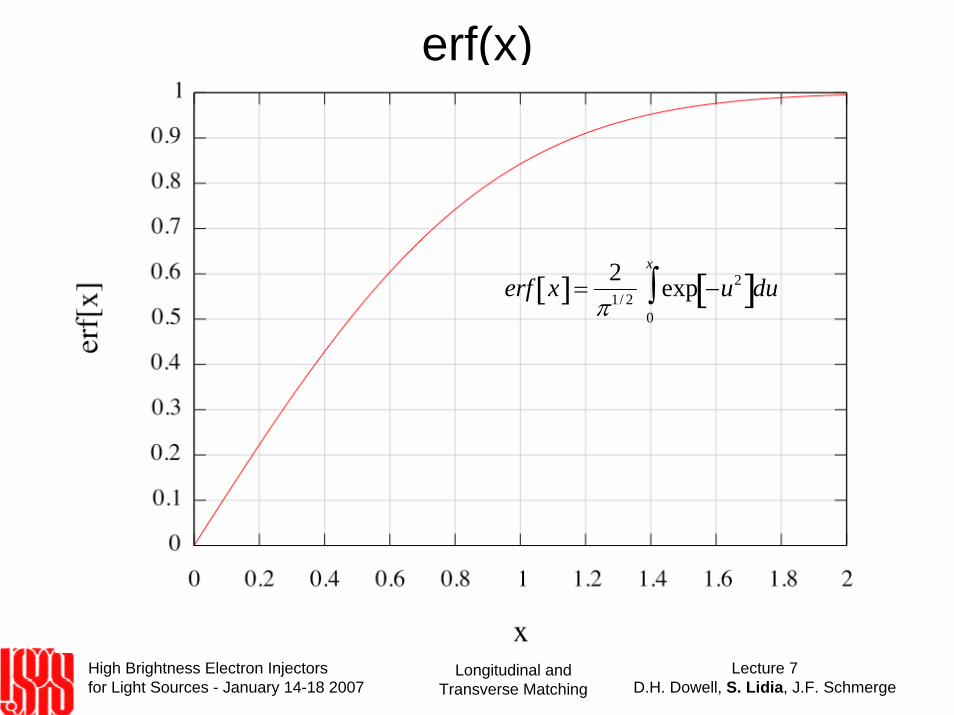
erf(x)
erf x[ ]=2
π1/ 2 exp −u2[ ]du0
x
∫
High Brightness Electron Injectors for Light Sources - January 14-18 2007
Lecture 7D.H. Dowell, S. Lidia, J.F. Schmerge
Longitudinal and Transverse Matching
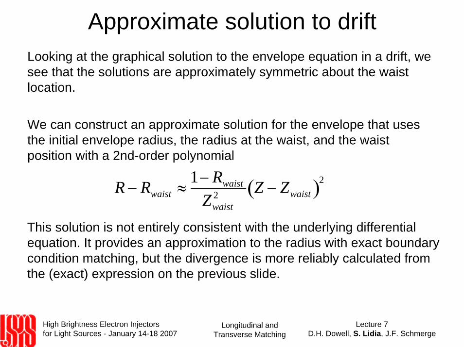
Approximate solution to driftLooking at the graphical solution to the envelope equation in a drift, we see that the solutions are approximately symmetric about the waist location.
We can construct an approximate solution for the envelope that uses the initial envelope radius, the radius at the waist, and the waist position with a 2nd-order polynomial
R − Rwaist ≈1− Rwaist
Zwaist2 Z − Zwaist( )2
This solution is not entirely consistent with the underlying differential equation. It provides an approximation to the radius with exact boundary condition matching, but the divergence is more reliably calculated from the (exact) expression on the previous slide.
High Brightness Electron Injectors for Light Sources - January 14-18 2007
Lecture 7D.H. Dowell, S. Lidia, J.F. Schmerge
Longitudinal and Transverse Matching
Linac structuresLinac sections are, of course, used to increase the energy of the beam.
Due to the nature of the RF electric and magnetic fields in the structures, the beam particles also receive time-dependent (phase-dependent) transverse impulses.
Longitudinal slices see varying focusing fields.
High Brightness Electron Injectors for Light Sources - January 14-18 2007
Lecture 7D.H. Dowell, S. Lidia, J.F. Schmerge
Longitudinal and Transverse Matching
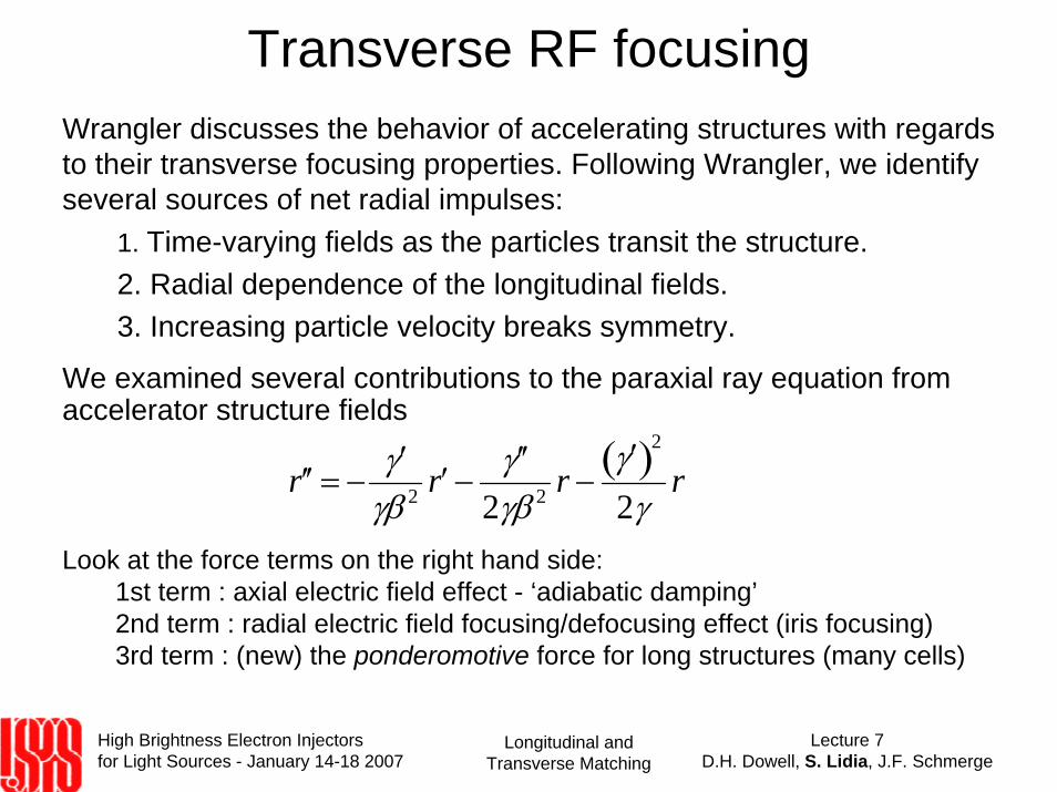
Transverse RF focusingWrangler discusses the behavior of accelerating structures with regards to their transverse focusing properties. Following Wrangler, we identify several sources of net radial impulses:
1. Time-varying fields as the particles transit the structure.2. Radial dependence of the longitudinal fields.3. Increasing particle velocity breaks symmetry.
′ ′ r = −′ γ
γβ 2 ′ r −′ ′ γ
2γβ 2 r −′ γ ( )2
2γr
We examined several contributions to the paraxial ray equation from accelerator structure fields
Look at the force terms on the right hand side:1st term : axial electric field effect - ‘adiabatic damping’2nd term : radial electric field focusing/defocusing effect (iris focusing)3rd term : (new) the ponderomotive force for long structures (many cells)
High Brightness Electron Injectors for Light Sources - January 14-18 2007
Lecture 7D.H. Dowell, S. Lidia, J.F. Schmerge
Longitudinal and Transverse Matching
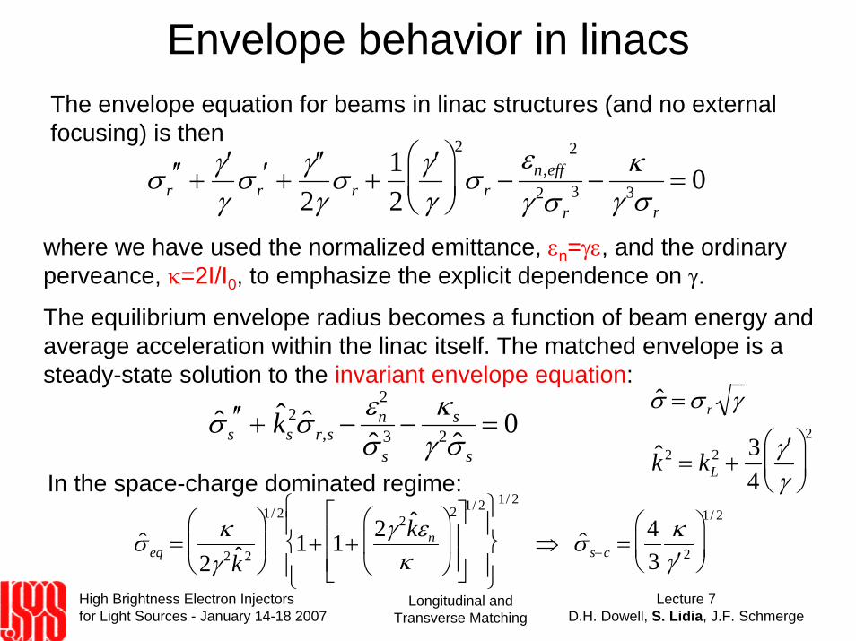
Envelope behavior in linacsThe envelope equation for beams in linac structures (and no external focusing) is then
σ r′′ +
′ γ γ
σ r′ +
′ ′ γ 2γ
σ r +12
′ γ γ
⎛
⎝ ⎜
⎞
⎠ ⎟
2
σ r −εn,eff
2
γ 2σ r3 −
κγ 3σ r
= 0
where we have used the normalized emittance, εn=γε, and the ordinary perveance, κ=2I/I0, to emphasize the explicit dependence on γ.
The equilibrium envelope radius becomes a function of beam energy and average acceleration within the linac itself. The matched envelope is a steady-state solution to the invariant envelope equation:
ˆ σ = σ r γ
ˆ k 2 = kL2 +
34
′ γ γ
⎛
⎝ ⎜
⎞
⎠ ⎟
2ˆ σ s′′ + ˆ k s2 ˆ σ r,s −
εn2
ˆ σ s3 −
κ s
γ 2 ˆ σ s= 0
ˆ σ eq =κ
2γ 2 ˆ k 2⎛
⎝ ⎜
⎞
⎠ ⎟
1/ 2
1+ 1+2γ 2 ˆ k εn
κ
⎛
⎝ ⎜
⎞
⎠ ⎟
2⎡
⎣ ⎢ ⎢
⎤
⎦ ⎥ ⎥
1/ 2⎧ ⎨ ⎪
⎩ ⎪
⎫ ⎬ ⎪
⎭ ⎪
1/ 2
⇒ ˆ σ s−c =43
κ′ γ 2
⎛
⎝ ⎜
⎞
⎠ ⎟
1/ 2
In the space-charge dominated regime:
High Brightness Electron Injectors for Light Sources - January 14-18 2007
Lecture 7D.H. Dowell, S. Lidia, J.F. Schmerge
Longitudinal and Transverse Matching
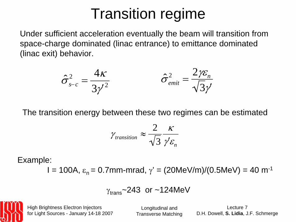
Transition regimeUnder sufficient acceleration eventually the beam will transition from space-charge dominated (linac entrance) to emittance dominated (linac exit) behavior.
ˆ σ s−c2 =
4κ3 ′ γ 2
ˆ σ emit2 =
2γεn
3 ′ γ
The transition energy between these two regimes can be estimated
γ transition ≈23
κ′ γ εn
Example: I = 100A, εn = 0.7mm-mrad, γ’ = (20MeV/m)/(0.5MeV) = 40 m-1
γtrans~243 or ~124MeV
High Brightness Electron Injectors for Light Sources - January 14-18 2007
Lecture 7D.H. Dowell, S. Lidia, J.F. Schmerge
Longitudinal and Transverse Matching
Emittance oscillation phase matching
ˆ k 2 = ˆ k 2 + 3ˆ ε 2
ˆ σ eq4 +
ˆ K ˆ σ eq
2 ≈ 2 ˆ k 2 = 2 kL2 +
34
′ γ γ
⎛
⎝ ⎜
⎞
⎠ ⎟
2⎡
⎣ ⎢ ⎢
⎤
⎦ ⎥ ⎥ ∝γ−2
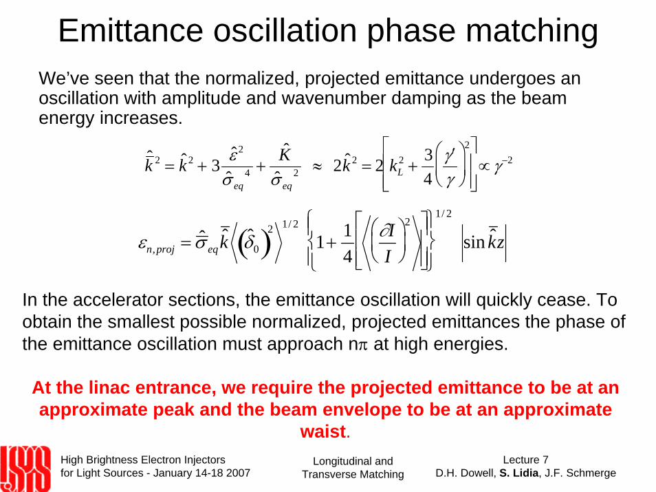
We’ve seen that the normalized, projected emittance undergoes an oscillation with amplitude and wavenumber damping as the beam energy increases.
In the accelerator sections, the emittance oscillation will quickly cease. To obtain the smallest possible normalized, projected emittances the phase of the emittance oscillation must approach nπ at high energies.
At the linac entrance, we require the projected emittance to be at an approximate peak and the beam envelope to be at an approximate
waist.
εn,proj = ˆ σ eqˆ k ˆ δ 0( )2 1/ 2
1+14
∂II
⎛ ⎝ ⎜
⎞ ⎠ ⎟
2⎡
⎣ ⎢ ⎢
⎤
⎦ ⎥ ⎥
⎧ ⎨ ⎪
⎩ ⎪
⎫ ⎬ ⎪
⎭ ⎪
1/ 2
sin ˆ k z
High Brightness Electron Injectors for Light Sources - January 14-18 2007
Lecture 7D.H. Dowell, S. Lidia, J.F. Schmerge
Longitudinal and Transverse Matching
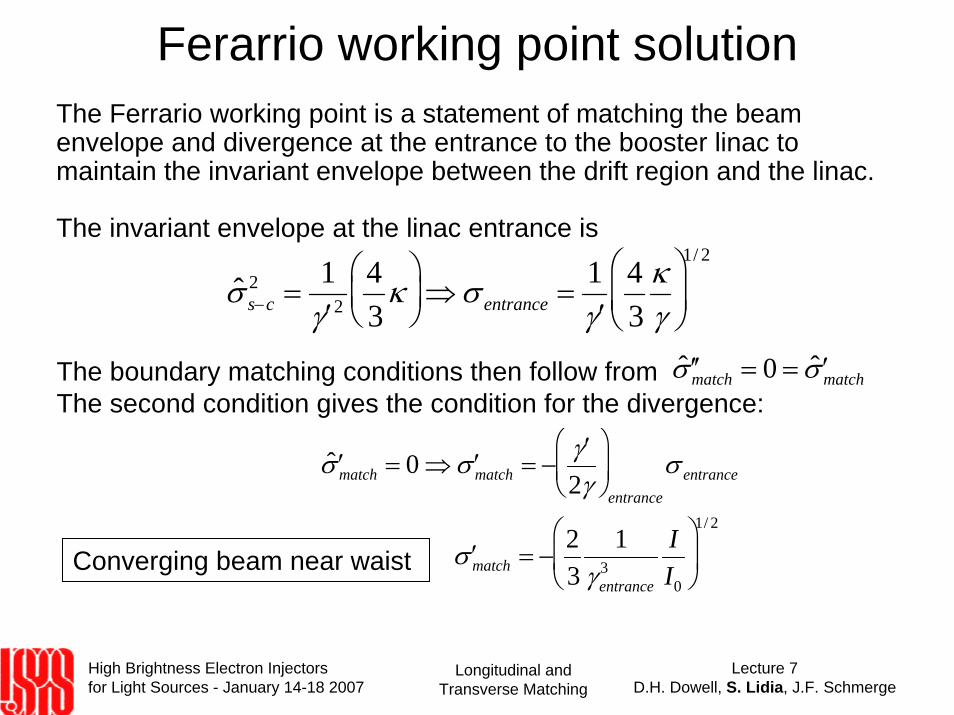
Ferarrio working point solutionThe Ferrario working point is a statement of matching the beam envelope and divergence at the entrance to the booster linac to maintain the invariant envelope between the drift region and the linac.
The invariant envelope at the linac entrance is
ˆ σ s−c2 =
1′ γ 2
43
κ⎛ ⎝ ⎜
⎞ ⎠ ⎟ ⇒ σ entrance =
1′ γ
43
κγ
⎛
⎝ ⎜
⎞
⎠ ⎟
1/ 2
The boundary matching conditions then follow from The second condition gives the condition for the divergence:
ˆ ′ ′ σ match = 0 = ˆ ′ σ match
ˆ ′ σ match = 0 ⇒ ′ σ match = −′ γ
2γ⎛
⎝ ⎜
⎞
⎠ ⎟
entrance
σ entrance
′ σ match = −23
1γ entrance
3II0
⎛
⎝ ⎜
⎞
⎠ ⎟
1/ 2
Converging beam near waist
High Brightness Electron Injectors for Light Sources - January 14-18 2007
Lecture 7D.H. Dowell, S. Lidia, J.F. Schmerge
Longitudinal and Transverse Matching
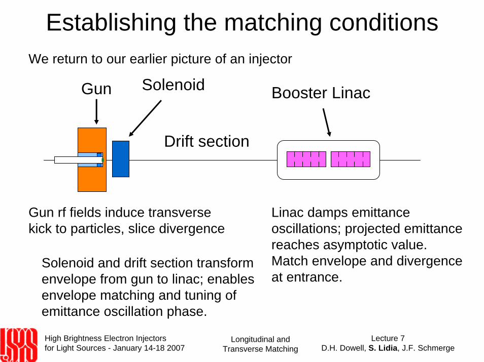
Establishing the matching conditionsWe return to our earlier picture of an injector
Gun Solenoid Booster Linac
Drift section
Gun rf fields induce transverse kick to particles, slice divergence
Linac damps emittance oscillations; projected emittance reaches asymptotic value.Match envelope and divergence at entrance.
Solenoid and drift section transformenvelope from gun to linac; enables envelope matching and tuning of emittance oscillation phase.
High Brightness Electron Injectors for Light Sources - January 14-18 2007
Lecture 7D.H. Dowell, S. Lidia, J.F. Schmerge
Longitudinal and Transverse Matching
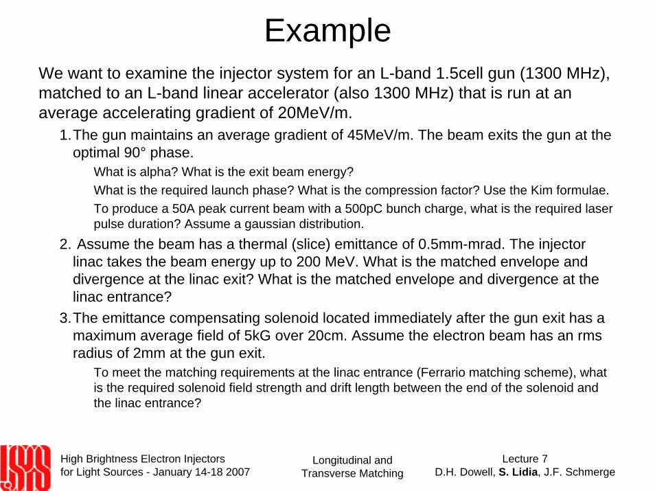
ExampleWe want to examine the injector system for an L-band 1.5cell gun (1300 MHz), matched to an L-band linear accelerator (also 1300 MHz) that is run at an average accelerating gradient of 20MeV/m.
1.The gun maintains an average gradient of 45MeV/m. The beam exits the gun at the optimal 90° phase.
What is alpha? What is the exit beam energy?What is the required launch phase? What is the compression factor? Use the Kim formulae.To produce a 50A peak current beam with a 500pC bunch charge, what is the required laser pulse duration? Assume a gaussian distribution.
2. Assume the beam has a thermal (slice) emittance of 0.5mm-mrad. The injector linac takes the beam energy up to 200 MeV. What is the matched envelope and divergence at the linac exit? What is the matched envelope and divergence at the linac entrance?
3.The emittance compensating solenoid located immediately after the gun exit has a maximum average field of 5kG over 20cm. Assume the electron beam has an rms radius of 2mm at the gun exit.
To meet the matching requirements at the linac entrance (Ferrario matching scheme), what is the required solenoid field strength and drift length between the end of the solenoid and the linac entrance?
High Brightness Electron Injectors for Light Sources - January 14-18 2007
Lecture 7D.H. Dowell, S. Lidia, J.F. Schmerge
Longitudinal and Transverse Matching
FEL sources require high peak currentsPeak currents from the RF gun tend to have an upper limit of ~100AFEL applications typically require anywhere from 500A (in a seeded VUV source) to multi-kA (for an xray SASE source).
Magnetic chicanes at high energy (>100MeV to 1 GeV) can provide a compression factor ~20-50, but do so with significant beam quality deterioration from CSR effects.
We need to consider means of increasing the peak current while maintaining transverse beam quality. Low energy (<10MeV) techniques may use a ballistic compression or rf velocity bunching.
These low energy techniques can boost peak currents but complicate emittance compression and matching to the main booster linac.
High Brightness Electron Injectors for Light Sources - January 14-18 2007
Lecture 7D.H. Dowell, S. Lidia, J.F. Schmerge
Longitudinal and Transverse Matching
Ballistic compressionBallistic methods are commonly used in klystrons. A velocity (energy) chirp is applied to a low energy beam such that the beam tail ‘catches up’ to the beam head over a suitable drift length. This works well with ~100keV beams in klystrons. In photoinjector systems with several MeV kinetic energy either the drift length or the required energy spread can be large.
Here, the peak current increases as the beam propagates as
where Kz is related to the bunch velocity spread. The condition to match the beam envelope to the channel now requires the focusingstrength (from, say, a solenoid field) to increase as the space charge defocusing strength increases. We can show that this is satisfied if
I z − zexit( )= Iexit 1+ Kz z − zexit( )[ ]
Bz z − zexit( )= Bexit 1+ Kz z − zexit( )
High Brightness Electron Injectors for Light Sources - January 14-18 2007
Lecture 7D.H. Dowell, S. Lidia, J.F. Schmerge
Longitudinal and Transverse Matching
RF Velocity BunchingRF velocity bunching uses a technique familiar from storage ringdynamics. The electron beam interacts with an accelerating rf field such that it executes a partial synchrotron oscillation before exiting with a smaller bunch length.
Serafini and Ferrario (ref.) analyzed the interaction of an electron beam with a linear accelerating structure. The technique involves injecting slow (v<c) electrons into the structure at phases where they fall behind the accelerating wave crest while still gaining energy.
In this case the beam current will increase with beam energy as
Matching the solenoid channel focusing to the envelope now requires
I z( )= Igun 1+ Kγ ′ γ z[ ]
Bz = B0 1+ Kγ ′ γ z