Embed Size (px)
Citation preview
IMAGINEIMAGINE
Maximiliano ArroyoMaximiliano ArroyoUT Division of Cardiovascular UT Division of Cardiovascular
DiseasesDiseasesJanuary 19January 19thth, 2006, 2006
In 1999, more than 1.83 million coronary angiograms In 1999, more than 1.83 million coronary angiograms were performed in the US. Only 1/3were performed in the US. Only 1/3rdrd were performed in were performed in conjunction of an interventional procedure.conjunction of an interventional procedure.
CTCT is the premier noninvasive modality for vascular is the premier noninvasive modality for vascular imaging of the thorax; the heart, however, has always imaging of the thorax; the heart, however, has always been technically challenging because of its continuous been technically challenging because of its continuous motion. motion.
The cross-sectional nature of The cross-sectional nature of CTCT may enable may enable assessment of the vessel wall. The potential for assessment of the vessel wall. The potential for noninvasive identification, characterization, and noninvasive identification, characterization, and quantification of atherosclerotic lesions and total disease quantification of atherosclerotic lesions and total disease burden within the coronary arteries is currently being burden within the coronary arteries is currently being evaluated. evaluated.
U. Joseph Schoepf. Radiology 2004;232:18-37
Modalities:Modalities:
EBCT: Introduced in 1984, was the first EBCT: Introduced in 1984, was the first system to enable ECG-synchronized CT system to enable ECG-synchronized CT imaging of the cardiac anatomy. With imaging of the cardiac anatomy. With presently available scanners, the routine presently available scanners, the routine protocol comprises a collimation of 3 mm, protocol comprises a collimation of 3 mm, a temporal resolution of 100 msec, and a temporal resolution of 100 msec, and prospective ECG triggering for sequential prospective ECG triggering for sequential acquisition of transverse images acquisition of transverse images consistently at the same phase of the consistently at the same phase of the cardiac cycle, typically during diastole. cardiac cycle, typically during diastole.
U. Joseph Schoepf. Radiology 2004;232:18-37
MDCTMDCT: Introduced in 1998, mechanical : Introduced in 1998, mechanical spiral CT systems with simultaneous spiral CT systems with simultaneous acquisition by four detector rows and a acquisition by four detector rows and a minimum rotation time of 500 msec were minimum rotation time of 500 msec were introduced. This provided a substantial introduced. This provided a substantial performance increase over the spiral CT performance increase over the spiral CT systems that had been available until then.systems that had been available until then.
U. Joseph Schoepf. Radiology 2004;232:18-37

A higher temporal resolution is enabled by A higher temporal resolution is enabled by means of faster gantry rotation speed combined means of faster gantry rotation speed combined with dedicated image reconstruction algorithms. with dedicated image reconstruction algorithms. The strategy that has been pursued to further The strategy that has been pursued to further improve fast high-resolution volume coverage is improve fast high-resolution volume coverage is to increase the number of sections that are to increase the number of sections that are simultaneously acquired. So far, this has simultaneously acquired. So far, this has resulted in the introduction of eight–, 10–, 16–, resulted in the introduction of eight–, 10–, 16–, 32–, 40–, and 64–detector row CT scanners with 32–, 40–, and 64–detector row CT scanners with further reduced gantry rotation times and further reduced gantry rotation times and minimum beam collimation widths of less than 1 minimum beam collimation widths of less than 1 mm.mm.
Presence of severe calcification is a limitation of Presence of severe calcification is a limitation of contrast-enhanced CT coronary angiography because contrast-enhanced CT coronary angiography because beam-hardening and partial-volume effects can beam-hardening and partial-volume effects can completely obscure the cross section of the vessel and completely obscure the cross section of the vessel and prevent assessment of the patency of the coronary prevent assessment of the patency of the coronary artery lumen. Owing to similar effects, metal objects artery lumen. Owing to similar effects, metal objects such as stents, surgical clips, and sternal wires can also such as stents, surgical clips, and sternal wires can also interfere with the evaluation of underlying structures. Use interfere with the evaluation of underlying structures. Use of the thinnest possible section width reduces partial-of the thinnest possible section width reduces partial-volume artifacts to some extent and improves volume artifacts to some extent and improves assessment of calcified coronary segments. assessment of calcified coronary segments.
U. Joseph Schoepf. Radiology 2004;232:18-37
ECG-synchronized CT Scan AcquisitionECG-synchronized CT Scan Acquisition
Prospective Triggering:Prospective Triggering: A trigger signal is derived from the patient’s ECG A trigger signal is derived from the patient’s ECG
on the basis of a prospective estimation of the on the basis of a prospective estimation of the present R-R interval, and the scan is started at a present R-R interval, and the scan is started at a defined time point after a detected R wave, defined time point after a detected R wave, usually during diastole. With MDCT, several usually during diastole. With MDCT, several sections are obtained simultaneously during one sections are obtained simultaneously during one scan acquisition with a cycle time that ordinarily scan acquisition with a cycle time that ordinarily allows image acquisition at every other allows image acquisition at every other heartbeat. In general, this strategy results in heartbeat. In general, this strategy results in shorter breath-hold times, and respiratory shorter breath-hold times, and respiratory artifacts are less likely to occur. artifacts are less likely to occur.
U. Joseph Schoepf. Radiology 2004;232:18-37
To improve temporal resolution, scan data To improve temporal resolution, scan data are only acquired during a partial scanner are only acquired during a partial scanner rotation (approximately two-thirds of a rotation (approximately two-thirds of a rotation with 240°–260° projection data), rotation with 240°–260° projection data), which covers the minimum amount of data which covers the minimum amount of data required for image reconstruction. In this required for image reconstruction. In this way, prospective ECG triggering is the way, prospective ECG triggering is the most dose-efficient method for ECG-most dose-efficient method for ECG-synchronized scanning. synchronized scanning.
However, only rather thick section collimation (3 However, only rather thick section collimation (3 mm with EBCT, 1.5 mm with 16—detector row mm with EBCT, 1.5 mm with 16—detector row CT) is usually being used for a prospectively CT) is usually being used for a prospectively ECG-triggered acquisition. Thus, the resulting ECG-triggered acquisition. Thus, the resulting data sets are less suitable for 3D reconstruction data sets are less suitable for 3D reconstruction of small cardiac anatomy. Also, the prospectively of small cardiac anatomy. Also, the prospectively ECG-triggered technique greatly depends on a ECG-triggered technique greatly depends on a regular heart rate of the patient and is bound to regular heart rate of the patient and is bound to result in misregistration in the presence of result in misregistration in the presence of arrhythmia. arrhythmia.
U. Joseph Schoepf. Radiology 2004;232:18-37
Retrospective Gating:Retrospective Gating: An alternative approach is retrospective ECG An alternative approach is retrospective ECG
gating. This generally enables greater flexibility gating. This generally enables greater flexibility for phase-consistent image reconstruction when for phase-consistent image reconstruction when examining a patient with a changing heart rate examining a patient with a changing heart rate during acquisition. Retrospective ECG gating during acquisition. Retrospective ECG gating requires multi–detector row spiral scanning with requires multi–detector row spiral scanning with a slow table motion and simultaneous recording a slow table motion and simultaneous recording of the ECG trace, which is used for retrospective of the ECG trace, which is used for retrospective linkage of scan data with particular phases of the linkage of scan data with particular phases of the cardiac cycle. cardiac cycle.
U. Joseph Schoepf. Radiology 2004;232:18-37
Retrospectively ECG-gated CT of the Retrospectively ECG-gated CT of the heart requires a highly overlapping spiral heart requires a highly overlapping spiral scan with a spiral table speed adapted to scan with a spiral table speed adapted to the heart rate to ensure complete phase-the heart rate to ensure complete phase-consistent coverage of the heart with consistent coverage of the heart with overlapping image sections.overlapping image sections.
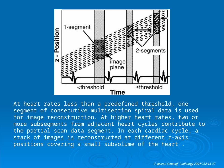
At heart rates less than a predefined threshold, one segment of consecutive multisection spiral data is used for image reconstruction. At higher heart rates, two or more subsegments from adjacent heart cycles contribute to the partial scan data segment. In each cardiac cycle, a stack of images is reconstructed at different z-axis positions covering a small subvolume of the heart .
U. Joseph Schoepf. Radiology 2004;232:18-37
The continuous spiral acquisition enables reconstruction The continuous spiral acquisition enables reconstruction of overlapping image sections, with a longitudinal spatial of overlapping image sections, with a longitudinal spatial resolution of up to 0.6 mm. resolution of up to 0.6 mm.
Retrospectively ECG-gated acquisition is the preferred Retrospectively ECG-gated acquisition is the preferred method for contrast-enhanced high-spatial-resolution method for contrast-enhanced high-spatial-resolution imaging of small cardiac structures, especially the imaging of small cardiac structures, especially the coronary arteries. coronary arteries.
Diastole is usually chosen for image reconstruction Diastole is usually chosen for image reconstruction because it is the phase of the cardiac cycle with the least because it is the phase of the cardiac cycle with the least motion; however, owing to the highly overlapping motion; however, owing to the highly overlapping acquisition, image data can be reconstructed for the acquisition, image data can be reconstructed for the entire course of the cardiac cycle. entire course of the cardiac cycle.
U. Joseph Schoepf. Radiology 2004;232:18-37
Optimizing Spatial ResolutionOptimizing Spatial ResolutionSpatial resolution is largely dependent on the type of Spatial resolution is largely dependent on the type of scanner available. The smallest detector widths range scanner available. The smallest detector widths range from 0.5 to 1.25 mm. from 0.5 to 1.25 mm.
The spatial resolution of four detector row CT is 0.6 x 0.6 The spatial resolution of four detector row CT is 0.6 x 0.6 x 1.0 mm, that of electron-beam CT is 0.7 x 0.7 x 3 mm, x 1.0 mm, that of electron-beam CT is 0.7 x 0.7 x 3 mm, and that of magnetic resonance (MR) coronary and that of magnetic resonance (MR) coronary angiography is 1.25 x 1.25 x 1.5 mm. Spiral CT allows angiography is 1.25 x 1.25 x 1.5 mm. Spiral CT allows volume acquisition and reconstruction of overlapping volume acquisition and reconstruction of overlapping sections, which improve z-axis resolution. The resolution sections, which improve z-axis resolution. The resolution of 16 detector row CT is up to 0.5 x 0.5 x 0.6 mm. This of 16 detector row CT is up to 0.5 x 0.5 x 0.6 mm. This resolution is approaching, but remains inferior to, that of resolution is approaching, but remains inferior to, that of conventional angiography, which is 0.2 x 0.2 mm. conventional angiography, which is 0.2 x 0.2 mm.
Harpreet P.Radiographics. 2003;23:S111-S125
Optimizing Temporal ResolutionOptimizing Temporal ResolutionThe temporal resolution is the amount of time it The temporal resolution is the amount of time it takes to acquire the necessary scan data to takes to acquire the necessary scan data to reconstruct an image. The temporal resolution of reconstruct an image. The temporal resolution of electron-beam CT is 100 msec, and that of MR electron-beam CT is 100 msec, and that of MR imaging is 100–150 msec. For multisection CT, it imaging is 100–150 msec. For multisection CT, it is primarily dependent on the time taken by the is primarily dependent on the time taken by the scanner to complete one gantry rotation but can scanner to complete one gantry rotation but can be modified by using partial scan reconstruction be modified by using partial scan reconstruction techniques. techniques.
Harpreet P.Radiographics. 2003;23:S111-S125
Radiation DoseRadiation Dose
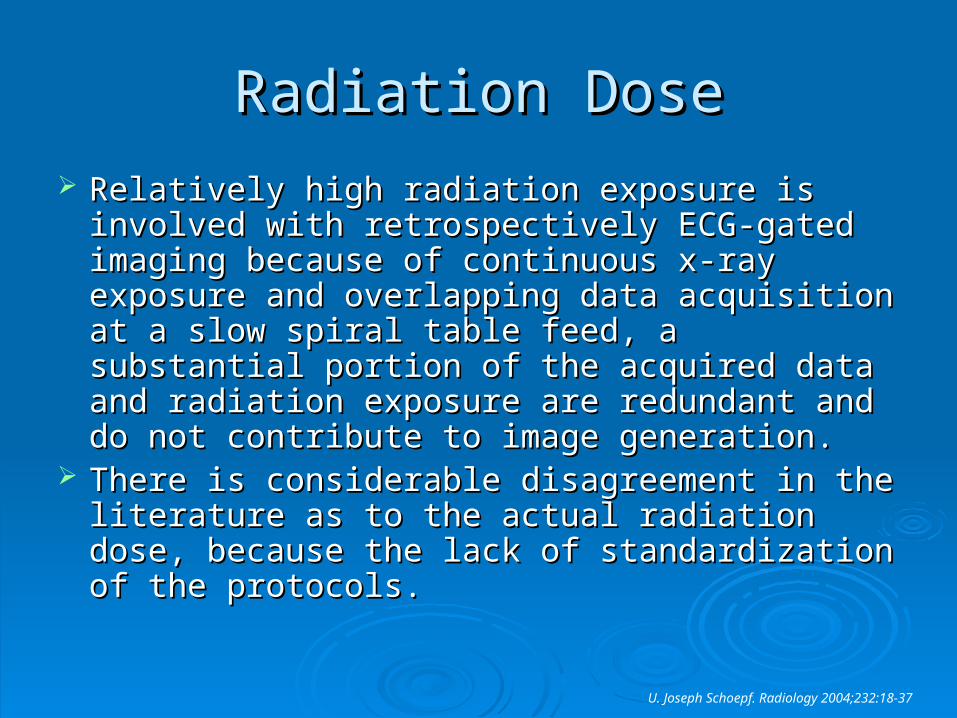
Relatively high radiation exposure is involved Relatively high radiation exposure is involved with retrospectively ECG-gated imaging because with retrospectively ECG-gated imaging because of continuous x-ray exposure and overlapping of continuous x-ray exposure and overlapping data acquisition at a slow spiral table feed, a data acquisition at a slow spiral table feed, a substantial portion of the acquired data and substantial portion of the acquired data and radiation exposure are redundant and do not radiation exposure are redundant and do not contribute to image generation. contribute to image generation.
There is considerable disagreement in the There is considerable disagreement in the literature as to the actual radiation dose, literature as to the actual radiation dose, because the lack of standardization of the because the lack of standardization of the protocols.protocols.
U. Joseph Schoepf. Radiology 2004;232:18-37
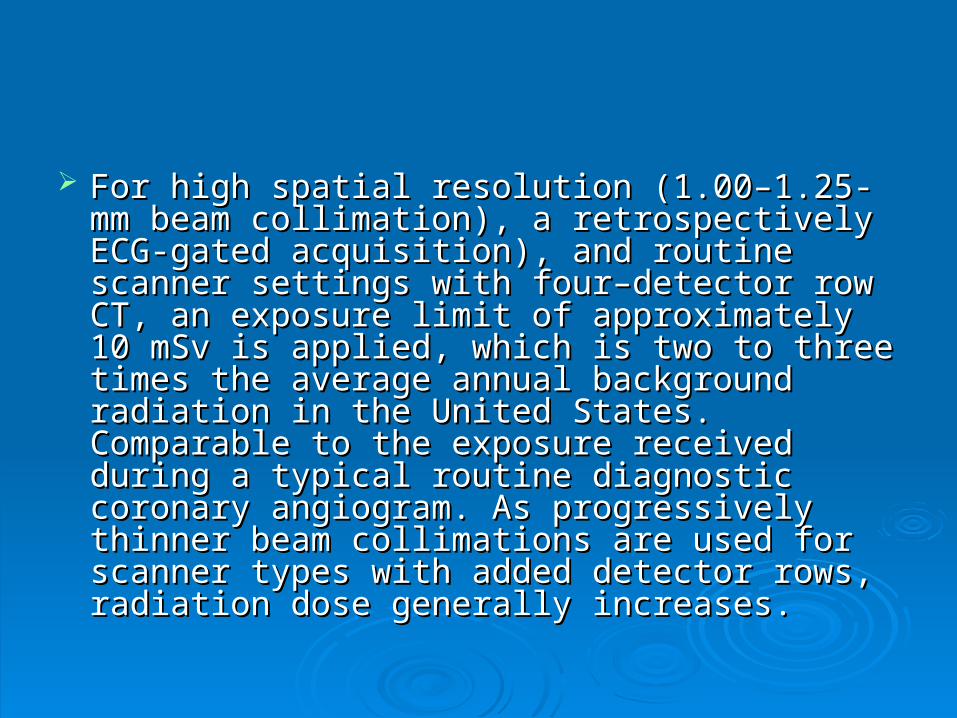
For high spatial resolution (1.00–1.25-mm beam For high spatial resolution (1.00–1.25-mm beam collimation), a retrospectively ECG-gated collimation), a retrospectively ECG-gated acquisition), and routine scanner settings with acquisition), and routine scanner settings with four–detector row CT, an exposure limit of four–detector row CT, an exposure limit of approximately 10 mSv is applied, which is two to approximately 10 mSv is applied, which is two to three times the average annual background three times the average annual background radiation in the United States. Comparable to the radiation in the United States. Comparable to the exposure received during a typical routine exposure received during a typical routine diagnostic coronary angiogram. As progressively diagnostic coronary angiogram. As progressively thinner beam collimations are used for scanner thinner beam collimations are used for scanner types with added detector rows, radiation dose types with added detector rows, radiation dose generally increases. generally increases.
CR Conti. Clin. Cardiol. 28:450-453
CR Conti. Clin. Cardiol. 28:450-453
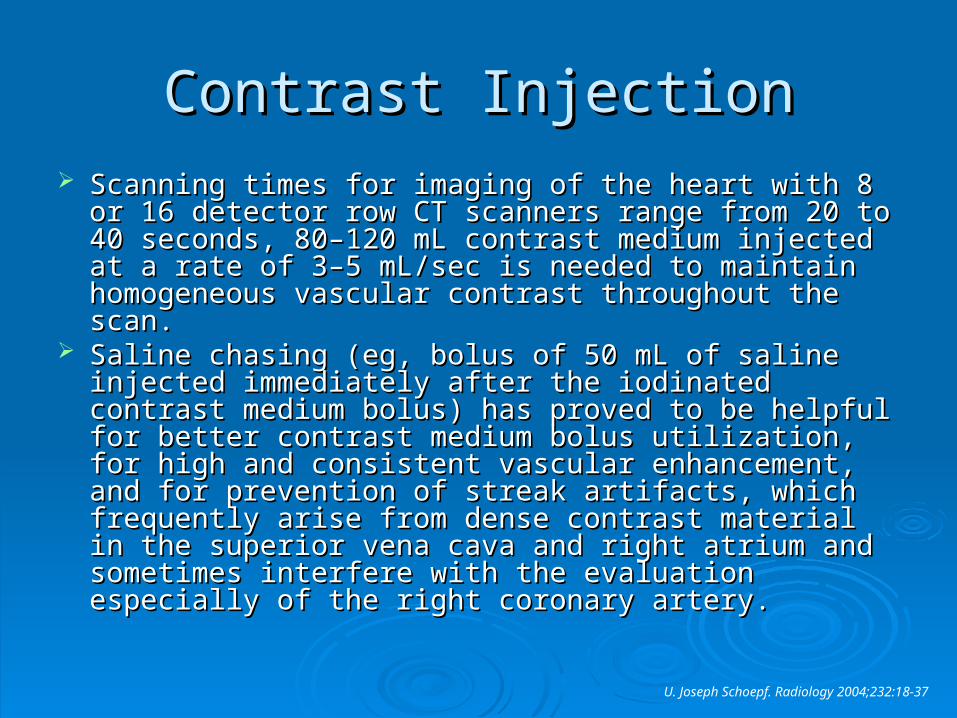
Contrast InjectionContrast Injection Scanning times for imaging of the heart with 8 or 16 Scanning times for imaging of the heart with 8 or 16
detector row CT scanners range from 20 to 40 seconds, detector row CT scanners range from 20 to 40 seconds, 80–120 mL contrast medium injected at a rate of 3–5 80–120 mL contrast medium injected at a rate of 3–5 mL/sec is needed to maintain homogeneous vascular mL/sec is needed to maintain homogeneous vascular contrast throughout the scan. contrast throughout the scan.
Saline chasing (eg, bolus of 50 mL of saline injected Saline chasing (eg, bolus of 50 mL of saline injected immediately after the iodinated contrast medium bolus) immediately after the iodinated contrast medium bolus) has proved to be helpful for better contrast medium has proved to be helpful for better contrast medium bolus utilization, for high and consistent vascular bolus utilization, for high and consistent vascular enhancement, and for prevention of streak artifacts, enhancement, and for prevention of streak artifacts, which frequently arise from dense contrast material in which frequently arise from dense contrast material in the superior vena cava and right atrium and sometimes the superior vena cava and right atrium and sometimes interfere with the evaluation especially of the right interfere with the evaluation especially of the right coronary artery.coronary artery.
U. Joseph Schoepf. Radiology 2004;232:18-37
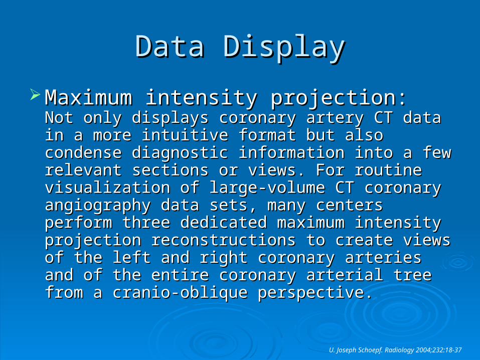
Data DisplayData Display
Maximum intensity projection:Maximum intensity projection: Not only Not only displays coronary artery CT data in a more displays coronary artery CT data in a more intuitive format but also condense diagnostic intuitive format but also condense diagnostic information into a few relevant sections or views. information into a few relevant sections or views. For routine visualization of large-volume CT For routine visualization of large-volume CT coronary angiography data sets, many centers coronary angiography data sets, many centers perform three dedicated maximum intensity perform three dedicated maximum intensity projection reconstructions to create views of the projection reconstructions to create views of the left and right coronary arteries and of the entire left and right coronary arteries and of the entire coronary arterial tree from a cranio-oblique coronary arterial tree from a cranio-oblique perspective. perspective.
U. Joseph Schoepf. Radiology 2004;232:18-37
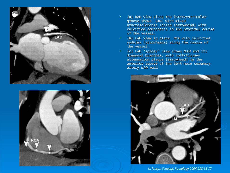
(a) (a) RAO view along the interventricular groove RAO view along the interventricular groove shows shows LADLAD, with mixed atherosclerotic lesion , with mixed atherosclerotic lesion (arrowhead) with calcified components in the (arrowhead) with calcified components in the proximal course of the vessel. proximal course of the vessel.
(b) (b) LAO view in plane LAO view in plane RCARCA with calcified nodules with calcified nodules (arrowheads) along the course of the vessel. (arrowheads) along the course of the vessel.
(c) (c) LAO "spider" view shows LAO "spider" view shows (LAD(LAD and its diagonal and its diagonal branches, with soft-tissue-attenuation plaque branches, with soft-tissue-attenuation plaque (arrowhead) in the anterior aspe(arrowhead) in the anterior aspectct of the left main of the left main coronary artery coronary artery (LM)(LM) wall. wall.
U. Joseph Schoepf. Radiology 2004;232:18-37
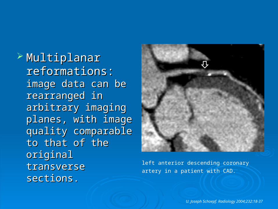
Multiplanar Multiplanar reformations: reformations: image image data can be data can be rearranged in rearranged in arbitrary imaging arbitrary imaging planes, with image planes, with image quality comparable to quality comparable to that of the original that of the original transverse sections. transverse sections. left anterior descending coronary artery in a
patient with CAD.
U. Joseph Schoepf. Radiology 2004;232:18-37
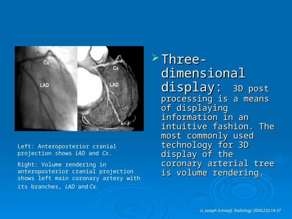
Three-Three-dimensional dimensional display:display: 3D post 3D post processing is a means of processing is a means of displaying information in displaying information in an intuitive fashion. The an intuitive fashion. The most commonly used most commonly used technology for 3D display technology for 3D display of the coronary arterial of the coronary arterial tree is volume rendering. tree is volume rendering.
Left: Anteroposterior cranial projection shows LAD and Cx.
Right: Volume rendering in anteroposterior cranial projection shows left main coronary
artery with its branches, LAD and Cx.
U. Joseph Schoepf. Radiology 2004;232:18-37
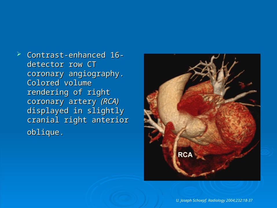
Contrast-enhanced 16-Contrast-enhanced 16-detector row CT coronary detector row CT coronary angiography. Colored volume angiography. Colored volume rendering of right coronary rendering of right coronary artery artery (RCA)(RCA) displayed in displayed in slightly cranial right anterior slightly cranial right anterior
oblique.oblique.
U. Joseph Schoepf. Radiology 2004;232:18-37
Contrast-enhanced CT of Coronary Artery Contrast-enhanced CT of Coronary Artery
Anomalies, Bypass Grafts, and StentsAnomalies, Bypass Grafts, and Stents MR imaging is limited with regard to MR imaging is limited with regard to
determination of the distal coronary arterial determination of the distal coronary arterial course. Therefore, course. Therefore, CTCT is the preferred is the preferred modality for evaluation of small collateral modality for evaluation of small collateral vessels, fistulas, and vessels originating vessels, fistulas, and vessels originating outside the normal sinuses. outside the normal sinuses.
U. Joseph Schoepf. Radiology 2004;232:18-37
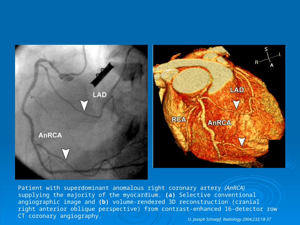
Patient with superdominant anomalous right coronary artery (AnRCA) supplying the majority of the myocardium. (a) Selective conventional angiographic image and (b) volume-rendered 3D reconstruction (cranial right anterior oblique perspective) from contrast-enhanced 16-detector row CT coronary angiography.
U. Joseph Schoepf. Radiology 2004;232:18-37
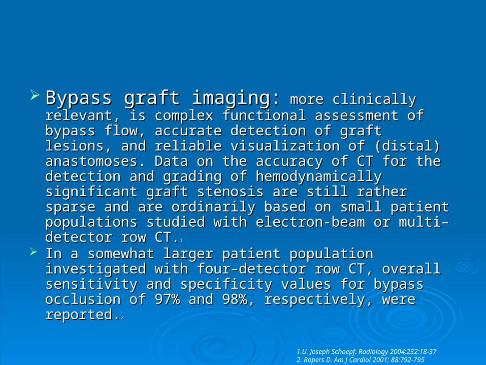
Bypass graft imaging:Bypass graft imaging: more clinically relevant, is more clinically relevant, is complex functional assessment of bypass flow, accurate complex functional assessment of bypass flow, accurate detection of graft lesions, and reliable visualization of detection of graft lesions, and reliable visualization of (distal) anastomoses. Data on the accuracy of CT for the (distal) anastomoses. Data on the accuracy of CT for the detection and grading of hemodynamically significant detection and grading of hemodynamically significant graft stenosis are still rather sparse and are ordinarily graft stenosis are still rather sparse and are ordinarily based on small patient populations studied with electron-based on small patient populations studied with electron-beam or multi–detector row CT.beam or multi–detector row CT.11
In a somewhat larger patient population investigated with In a somewhat larger patient population investigated with four–detector row CT, overall sensitivity and specificity four–detector row CT, overall sensitivity and specificity values for bypass occlusion of 97% and 98%, values for bypass occlusion of 97% and 98%, respectively, were reported.respectively, were reported.22
1.U. Joseph Schoepf. Radiology 2004;232:18-37 2. Ropers D. Am J Cardiol 2001; 88:792-795
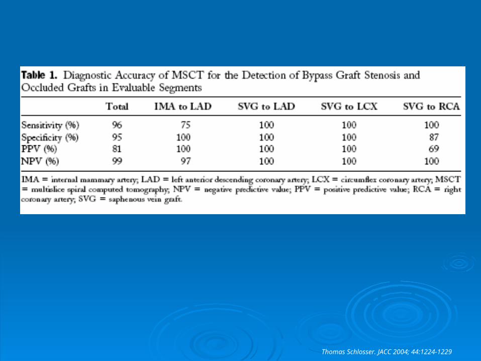
Thomas Schlosser. JACC 2004; 44:1224-1229
All IMA grafts could be visualized with diagnostic All IMA grafts could be visualized with diagnostic image quality, whereas only 28 of 37 (76%) of image quality, whereas only 28 of 37 (76%) of the distal anastomoses to the LAD and 3 of 5 the distal anastomoses to the LAD and 3 of 5 (60%) of the distal anastomoses to the diagonal (60%) of the distal anastomoses to the diagonal branches could be evaluated. branches could be evaluated.
A total of 11 of 42 (26%) of the distal IMA A total of 11 of 42 (26%) of the distal IMA anastomoses were classified as unevaluable anastomoses were classified as unevaluable due to poor opacification and artifacts caused due to poor opacification and artifacts caused by metal clips. by metal clips.
Thomas Schlosser. JACC 2004; 44:1224-1229
MSCT permitted visualization of all proximal and distal anastomoses MSCT permitted visualization of all proximal and distal anastomoses of venous grafts to the LAD. of venous grafts to the LAD.
Invasive coronary angiography revealed 8 venous grafts to the LCX Invasive coronary angiography revealed 8 venous grafts to the LCX to be occluded, all correctly diagnosed by MSCT. All proximal and to be occluded, all correctly diagnosed by MSCT. All proximal and 25 of 33 (76%) distal anastomoses in the LCX region were 25 of 33 (76%) distal anastomoses in the LCX region were adequately seen on MSCT. The remaining 8 distal anastomoses adequately seen on MSCT. The remaining 8 distal anastomoses (24%) were classified as unevaluable due to poor opacification (24%) were classified as unevaluable due to poor opacification and/or artifacts caused by cardiac motion.and/or artifacts caused by cardiac motion.
All proximal and 22 distal anastomoses (63%) to the RCA, could be All proximal and 22 distal anastomoses (63%) to the RCA, could be visualized. A total of 13 of 35 (37%) of the distal anastomoses were visualized. A total of 13 of 35 (37%) of the distal anastomoses were classified as unevaluable. Overall, 83 of 112 (74%) distal classified as unevaluable. Overall, 83 of 112 (74%) distal anastomoses could be evaluated. anastomoses could be evaluated.
The unevaluable distal anastomoses were estimated as stenotic. The unevaluable distal anastomoses were estimated as stenotic. This results in a lower specificity (68%) and positive predictive value This results in a lower specificity (68%) and positive predictive value (PPV) (37%) compared with the separate analysis of the evaluable (PPV) (37%) compared with the separate analysis of the evaluable segments (specificity 95%, PPV 81%). segments (specificity 95%, PPV 81%).
Thomas Schlosser. JACC 2004; 44:1224-1229
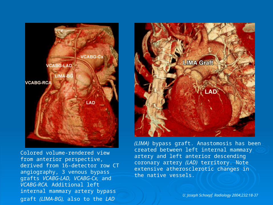
Colored volume-rendered view from anterior perspective, derived from 16-detector row CT angiography, 3 venous bypass grafts VCABG-LAD, VCABG-Cx, and VCABG-RCA. Additional left internal mammary artery bypass graft (LIMA-BG),
also to the LAD
(LIMA) bypass graft. Anastomosis has been created between left internal mammary artery and left anterior descending coronary artery (LAD) territory. Note extensive atherosclerotic changes in the native vessels.
U. Joseph Schoepf. Radiology 2004;232:18-37
Coronary stentsCoronary stents have been notoriously difficult have been notoriously difficult to assess with CT. Contrast-enhanced CT can to assess with CT. Contrast-enhanced CT can be used to assess stent patency on the basis of be used to assess stent patency on the basis of contrast enhancement in the course of the artery contrast enhancement in the course of the artery with the stent, because an unenhanced distal with the stent, because an unenhanced distal coronary artery lumen usually reflects critical in-coronary artery lumen usually reflects critical in-stent restenosis. However, assessment of the stent restenosis. However, assessment of the stent lumen for nonocclusive in-stent restenosis stent lumen for nonocclusive in-stent restenosis due to neointimal hyperplasia remains due to neointimal hyperplasia remains challenging. challenging.
U. Joseph Schoepf. Radiology 2004;232:18-37
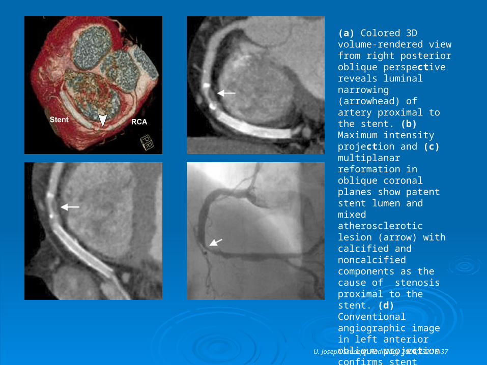
(a) Colored 3D volume-rendered view from right posterior oblique perspective reveals luminal narrowing (arrowhead) of artery proximal to the stent. (b) Maximum intensity projection and (c) multiplanar reformation in oblique coronal planes show patent stent lumen and mixed atherosclerotic lesion (arrow) with calcified and noncalcified components as the cause of stenosis proximal to the stent. (d) Conventional angiographic image in left anterior oblique projection confirms stent patency and
presence of stenosis.
U. Joseph Schoepf. Radiology 2004;232:18-37
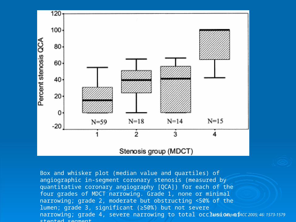
Box and whisker plot (median value and quartiles) of angiographic in-segment coronary stenosis (measured by quantitative coronary angiography [QCA]) for each of the four grades of MDCT narrowing. Grade 1, none or minimal narrowing; grade 2, moderate but obstructing <50% of the lumen; grade 3, significant (≥50%) but not severe narrowing; grade 4, severe narrowing to total occlusion of stented segment.
Tamar Gaspar, JACC 2005; 46: 1573-1579
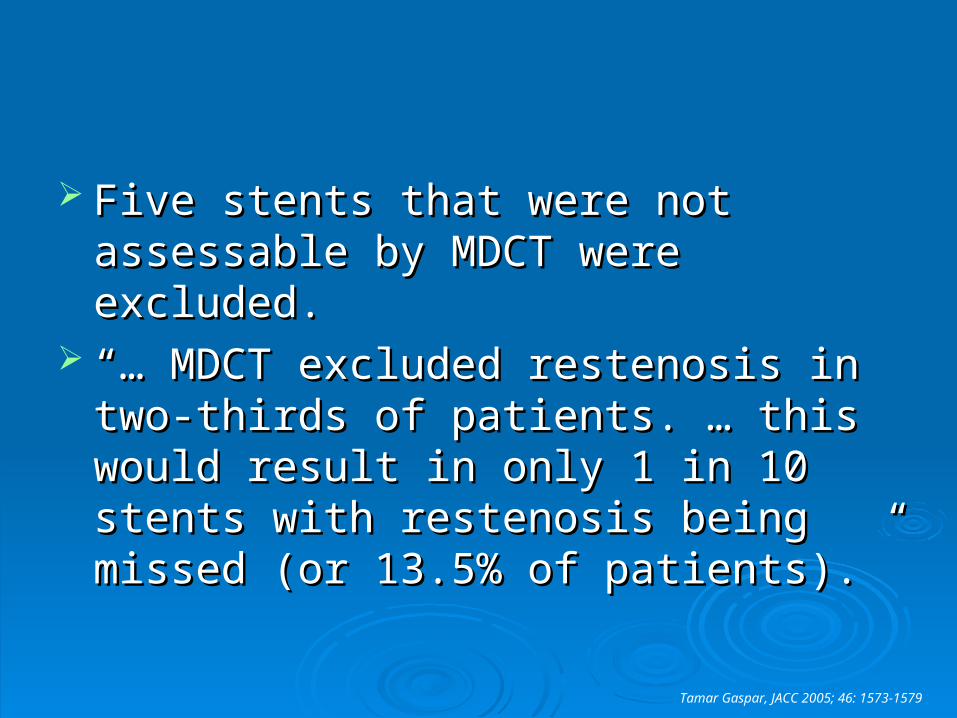
Five stents that were not assessable by Five stents that were not assessable by MDCT were excluded. MDCT were excluded.
“… “… MDCT excluded restenosis in two-MDCT excluded restenosis in two-thirds of patients. … this would result in thirds of patients. … this would result in only 1 in 10 stents with restenosis being only 1 in 10 stents with restenosis being missed (or 13.5% of patients).” missed (or 13.5% of patients).”
Tamar Gaspar, JACC 2005; 46: 1573-1579
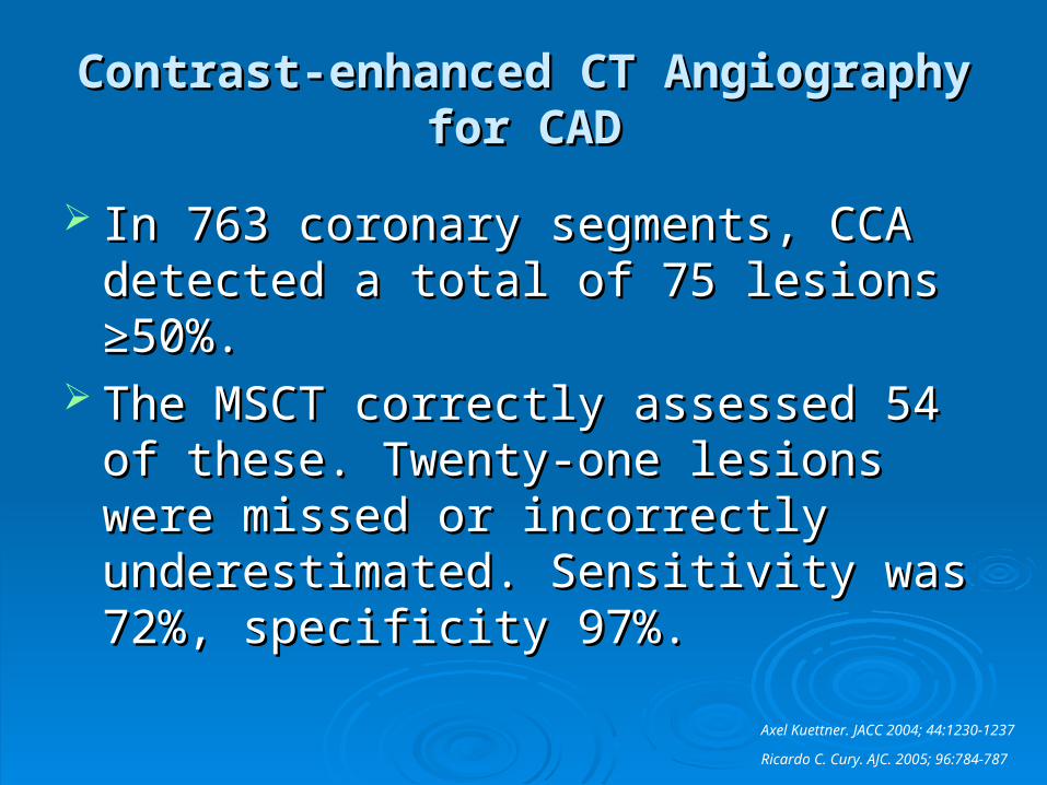
Contrast-enhanced CT Angiography for Contrast-enhanced CT Angiography for CADCAD
In 763 coronary segments, CCA detected In 763 coronary segments, CCA detected a total of 75 lesions ≥50%. a total of 75 lesions ≥50%.
The MSCT correctly assessed 54 of these. The MSCT correctly assessed 54 of these. Twenty-one lesions were missed or Twenty-one lesions were missed or incorrectly underestimated. Sensitivity was incorrectly underestimated. Sensitivity was 72%, specificity 97%. 72%, specificity 97%.
Axel Kuettner. JACC 2004; 44:1230-1237
Ricardo C. Cury. AJC. 2005; 96:784-787
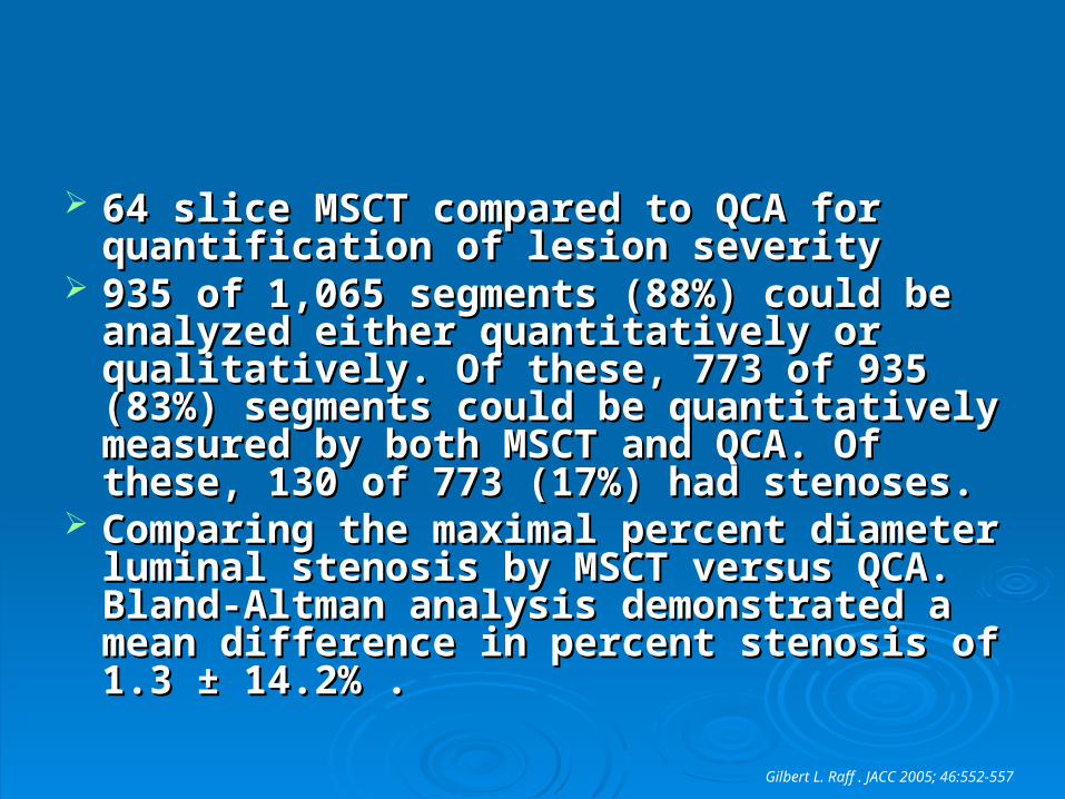
64 slice MSCT compared to QCA for 64 slice MSCT compared to QCA for quantification of lesion severityquantification of lesion severity
935 of 1,065 segments (88%) could be 935 of 1,065 segments (88%) could be analyzed either quantitatively or qualitatively. analyzed either quantitatively or qualitatively. Of these, 773 of 935 (83%) segments could Of these, 773 of 935 (83%) segments could be quantitatively measured by both MSCT be quantitatively measured by both MSCT and QCA. Of these, 130 of 773 (17%) had and QCA. Of these, 130 of 773 (17%) had stenoses. stenoses.
Comparing the maximal percent diameter Comparing the maximal percent diameter luminal stenosis by MSCT versus QCA. luminal stenosis by MSCT versus QCA. Bland-Altman analysis demonstrated a mean Bland-Altman analysis demonstrated a mean difference in percent stenosis of 1.3 ± 14.2% . difference in percent stenosis of 1.3 ± 14.2% .
Gilbert L. Raff . JACC 2005; 46:552-557
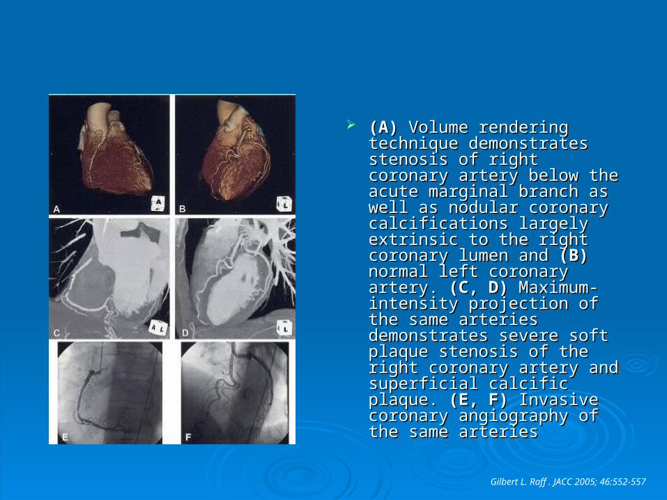
(A)(A) Volume rendering Volume rendering technique demonstrates technique demonstrates stenosis of right coronary stenosis of right coronary artery below the acute artery below the acute marginal branch as well as marginal branch as well as nodular coronary calcifications nodular coronary calcifications largely extrinsic to the right largely extrinsic to the right coronary lumen and coronary lumen and (B)(B) normal left coronary artery. normal left coronary artery. (C, (C, D)D) Maximum-intensity Maximum-intensity projection of the same arteries projection of the same arteries demonstrates severe soft demonstrates severe soft plaque stenosis of the right plaque stenosis of the right coronary artery and superficial coronary artery and superficial calcific plaque. calcific plaque. (E, F)(E, F) Invasive Invasive coronary angiography of the coronary angiography of the same arteries same arteries
Gilbert L. Raff . JACC 2005; 46:552-557
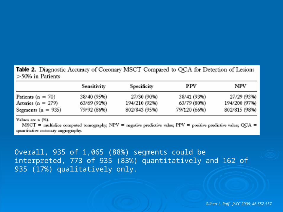
Overall, 935 of 1,065 (88%) segments could be interpreted, 773 of 935 (83%) quantitatively and 162 of 935 (17%) qualitatively only.
Gilbert L. Raff . JACC 2005; 46:552-557
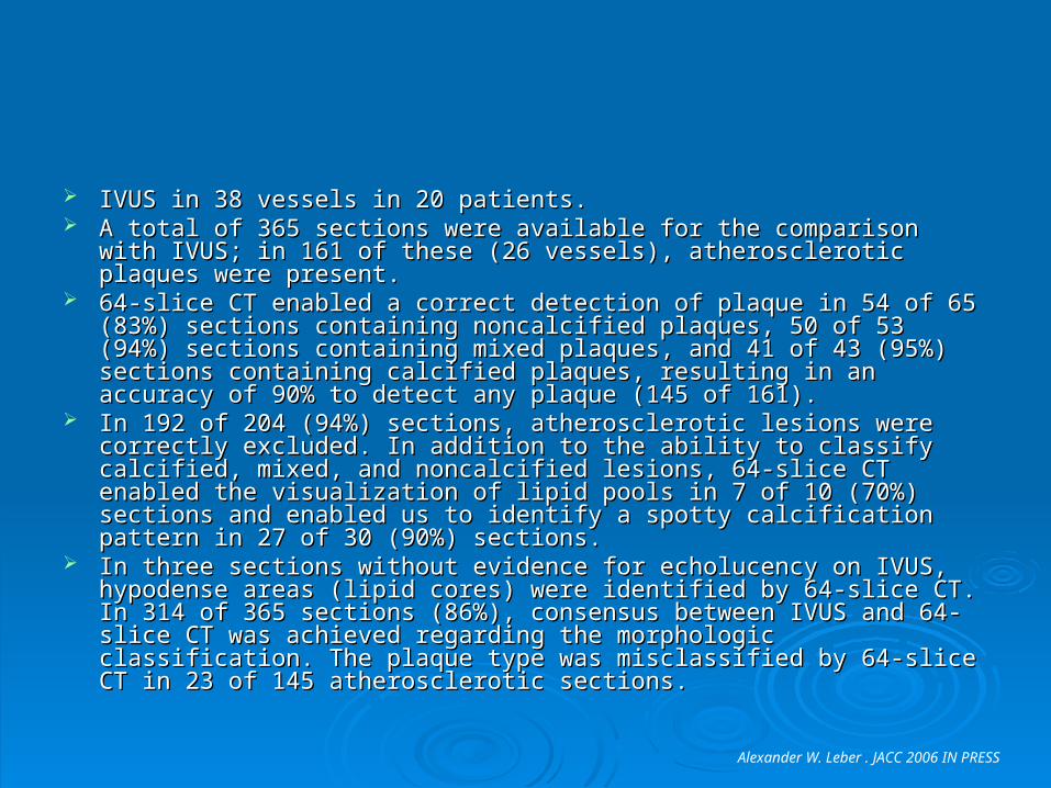
IVUS in 38 vessels in 20 patients. IVUS in 38 vessels in 20 patients. A total of 365 sections were available for the comparison with IVUS; in 161 A total of 365 sections were available for the comparison with IVUS; in 161
of these (26 vessels), atherosclerotic plaques were present. of these (26 vessels), atherosclerotic plaques were present. 64-slice CT enabled a correct detection of plaque in 54 of 65 (83%) sections 64-slice CT enabled a correct detection of plaque in 54 of 65 (83%) sections
containing noncalcified plaques, 50 of 53 (94%) sections containing mixed containing noncalcified plaques, 50 of 53 (94%) sections containing mixed plaques, and 41 of 43 (95%) sections containing calcified plaques, resulting plaques, and 41 of 43 (95%) sections containing calcified plaques, resulting in an accuracy of 90% to detect any plaque (145 of 161). in an accuracy of 90% to detect any plaque (145 of 161).
In 192 of 204 (94%) sections, atherosclerotic lesions were correctly In 192 of 204 (94%) sections, atherosclerotic lesions were correctly excluded. In addition to the ability to classify calcified, mixed, and excluded. In addition to the ability to classify calcified, mixed, and noncalcified lesions, 64-slice CT enabled the visualization of lipid pools in 7 noncalcified lesions, 64-slice CT enabled the visualization of lipid pools in 7 of 10 (70%) sections and enabled us to identify a spotty calcification pattern of 10 (70%) sections and enabled us to identify a spotty calcification pattern in 27 of 30 (90%) sections. in 27 of 30 (90%) sections.
In three sections without evidence for echolucency on IVUS, hypodense In three sections without evidence for echolucency on IVUS, hypodense areas (lipid cores) were identified by 64-slice CT. In 314 of 365 sections areas (lipid cores) were identified by 64-slice CT. In 314 of 365 sections (86%), consensus between IVUS and 64-slice CT was achieved regarding (86%), consensus between IVUS and 64-slice CT was achieved regarding the morphologic classification. The plaque type was misclassified by 64-the morphologic classification. The plaque type was misclassified by 64-slice CT in 23 of 145 atherosclerotic sections. slice CT in 23 of 145 atherosclerotic sections.
Alexander W. Leber . JACC 2006 IN PRESS
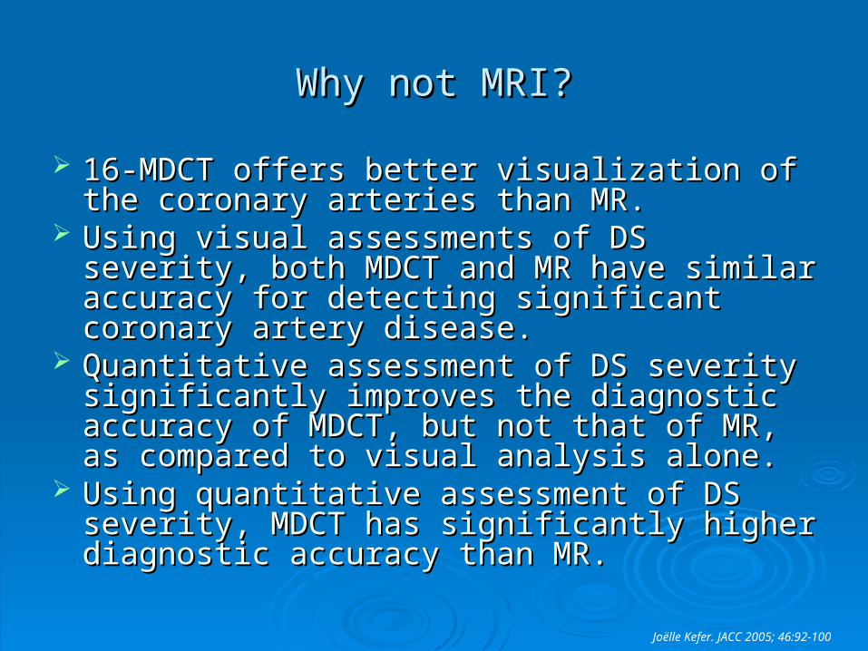
Why not MRI?Why not MRI?
16-MDCT offers better visualization of the 16-MDCT offers better visualization of the coronary arteries than MR.coronary arteries than MR.
Using visual assessments of DS severity, both Using visual assessments of DS severity, both MDCT and MR have similar accuracy for MDCT and MR have similar accuracy for detecting significant coronary artery disease.detecting significant coronary artery disease.
Quantitative assessment of DS severity Quantitative assessment of DS severity significantly improves the diagnostic accuracy of significantly improves the diagnostic accuracy of MDCT, but not that of MR, as compared to MDCT, but not that of MR, as compared to visual analysis alone.visual analysis alone.
Using quantitative assessment of DS severity, Using quantitative assessment of DS severity, MDCT has significantly higher diagnostic MDCT has significantly higher diagnostic accuracy than MR.accuracy than MR.
Joëlle Kefer. JACC 2005; 46:92-100
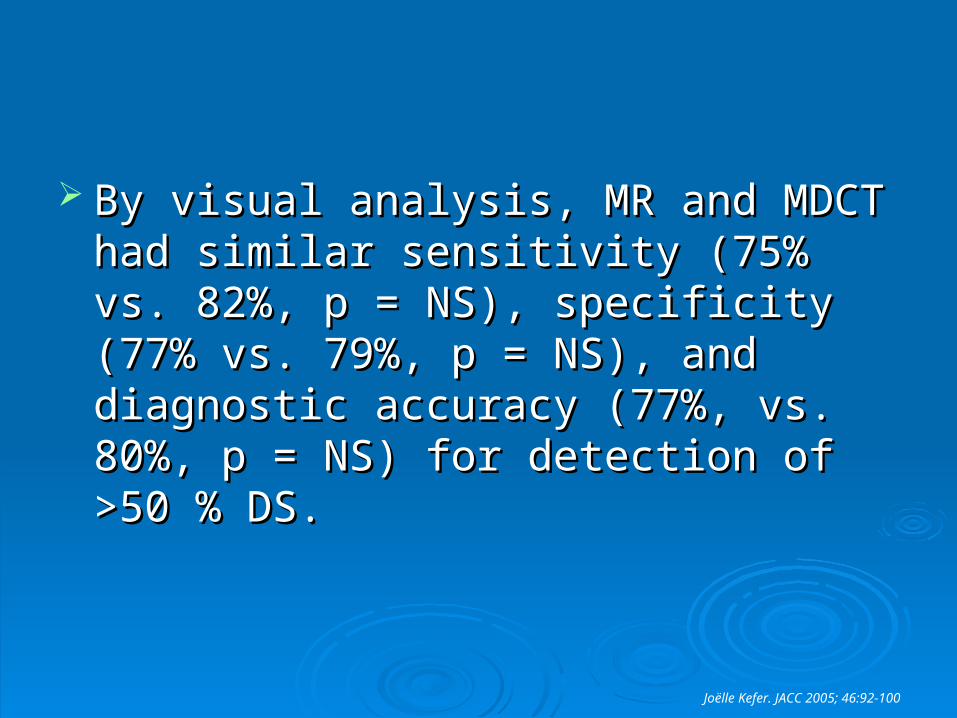
By visual analysis, MR and MDCT had By visual analysis, MR and MDCT had similar sensitivity (75% vs. 82%, p = NS), similar sensitivity (75% vs. 82%, p = NS), specificity (77% vs. 79%, p = NS), and specificity (77% vs. 79%, p = NS), and diagnostic accuracy (77%, vs. 80%, p = diagnostic accuracy (77%, vs. 80%, p = NS) for detection of >50 % DS. NS) for detection of >50 % DS.
Joëlle Kefer. JACC 2005; 46:92-100
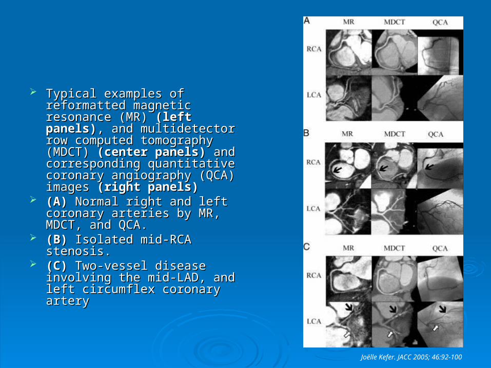
Typical examples of Typical examples of reformatted magnetic reformatted magnetic resonance (MR) resonance (MR) (left panels)(left panels), , and multidetector row and multidetector row computed tomography (MDCT) computed tomography (MDCT) (center panels)(center panels) and and corresponding quantitative corresponding quantitative coronary angiography (QCA) coronary angiography (QCA) images images (right panels)(right panels)
(A)(A) Normal right and left Normal right and left coronary arteries by MR, coronary arteries by MR, MDCT, and QCA. MDCT, and QCA.
(B)(B) Isolated mid-RCA stenosis. Isolated mid-RCA stenosis. (C)(C) Two-vessel disease Two-vessel disease
involving the mid-LAD, and left involving the mid-LAD, and left circumflex coronary arterycircumflex coronary artery
Joëlle Kefer. JACC 2005; 46:92-100
ConclusionsConclusions
MDCT is now more comparable to QCA, with MDCT is now more comparable to QCA, with excellent sensitivity and specificity in excellent sensitivity and specificity in experienced centers.experienced centers.
Further evolution of MDCT (more and faster Further evolution of MDCT (more and faster detectors, software improvement) will likely detectors, software improvement) will likely provide a better spatial and temporal resolution.provide a better spatial and temporal resolution.
Currently, MDCT is not the test of choice in Currently, MDCT is not the test of choice in patients with prior CABG, stents, severely patients with prior CABG, stents, severely calcified lesions; perhaps also patients with calcified lesions; perhaps also patients with elevated HR, and obese.elevated HR, and obese.
MDCT does not have the capability of assessing the MDCT does not have the capability of assessing the distribution of various morphologic patterns of calcium distribution of various morphologic patterns of calcium and their relation to other “soft” plaque components; and their relation to other “soft” plaque components; further plaque characterization (e.g., lipid pools and further plaque characterization (e.g., lipid pools and fibrous tissue), a prerequisite for the identification of fibrous tissue), a prerequisite for the identification of most vulnerable lesions, is not yet a workable reality, most vulnerable lesions, is not yet a workable reality, even with the 64-slice machines in their current even with the 64-slice machines in their current configuration. configuration.
The noninvasive identification of plaque components The noninvasive identification of plaque components subtending vulnerable lesions will require additional subtending vulnerable lesions will require additional improvement in the primary instrumentation, software, improvement in the primary instrumentation, software, perhaps ?? the use of hybrid constructs (e.g., with perhaps ?? the use of hybrid constructs (e.g., with positron emission tomography).positron emission tomography).
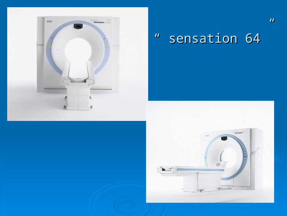
The “ sensation 64”The “ sensation 64”

Thanks!Thanks!