Embed Size (px)
Citation preview
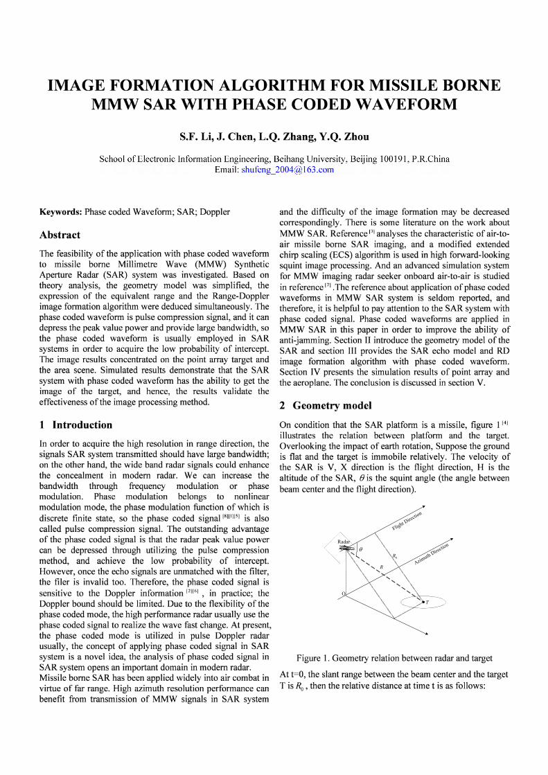
IMAGE FORMATION ALGORITHM FOR MISSILE BORNEMMW SAR WITH PHASE CODED WAVEFORM
S.F. Li, J. Chen, L.Q. Zhang, Y.Q. Zhou
School of Electronic Information Engineering, Beihang University, Beijing 100191, P.R.ChinaEmail: [email protected]
Keywords: Phase coded Waveform; SAR; Doppler
Abstract
The feasibility of the application with phase coded waveformto missile borne Millimetre Wave (MMW) SyntheticAperture Radar (SAR) system was investigated. Based ontheory analysis, the geometry model was simplified, theexpression of the equivalent range and the Range-Dopplerimage formation algorithm were deduced simultaneously. Thephase coded waveform is pulse compression signal, and it candepress the peak value power and provide large bandwidth, sothe phase coded waveform is usually employed in SARsystems in order to acquire the low probability of intercept.The image results concentrated on the point array target andthe area scene. Simulated results demonstrate that the SARsystem with phase coded waveform has the ability to get theimage of the target, and hence, the results validate theeffectiveness of the image processing method.
1 Introduction
In order to acquire the high resolution in range direction, thesignals SAR system transmitted should have large bandwidth;on the other hand, the wide band radar signals could enhancethe concealment in modem radar. We can increase thebandwidth through frequency modulation or phasemodulation. Phase modulation belongs to nonlinearmodulation mode, the phase modulation function of which isdiscrete finite state, so the phase coded signal [8][1][5] is alsocalled pulse compression signal. The outstanding advantageof the phase coded signal is that the radar peak value powercan be depressed through utilizing the pulse compressionmethod, and achieve the low probability of intercept.However, once the echo signals are unmatched with the filter,the filer is invalid too. Therefore, the phase coded signal issensitive to the Doppler information [2][6] , in practice; theDoppler bound should be limited. Due to the flexibility of thephase coded mode, the high performance radar usually use thephase coded signal to realize the wave fast change. At present,the phase coded mode is utilized in pulse Doppler radarusually, the concept of applying phase coded signal in SARsystem is a novel idea, the analysis of phase coded signal inSAR system opens an important domain in modem radar.Missile borne SAR has been applied widely into air combat invirtue of far range. High azimuth resolution performance canbenefit from transmission of MMW signals in SAR system
and the difficulty of the image formation may be decreasedcorrespondingly. There is some literature on the work aboutMMW SAR. Reference [3] analyses the characteristic of air-toair missile borne SAR imaging, and a modified extendedchirp scaling (ECS) algorithm is used in high forward-lookingsquint image processing. And an advanced simulation systemfor MMW imaging radar seeker onboard air-to-air is studiedin reference [7] •The reference about application of phase codedwaveforms in MMW SAR system is seldom reported, andtherefore, it is helpful to pay attention to the SAR system withphase coded signal. Phase coded waveforms are applied inMMW SAR in this paper in order to improve the ability ofanti-jamming. Section II introduce the geometry model of theSAR and section III provides the SAR echo model and RDimage formation algorithm with phase coded waveform.Section IV presents the simulation results of point array andthe aeroplane. The conclusion is discussed in section V.
2 Geometry model
On condition that the SAR platform is a missile, figure 1[4]
illustrates the relation between platform and the target.Overlooking the impact of earth rotation, Suppose the groundis flat and the target is immobile relatively. The velocity ofthe SAR is V, X direction is the flight direction, H is thealtitude of the SAR, ()is the squint angle (the angle betweenbeam center and the flight direction).
Radar
I"'" ()I
I \ -, RI \ -,II
!I
o!
Figure 1. Geometry relation between radar and target
At t=O, the slant range between the beam center and the targetT is Ra , then the relative distance at time t is as follows:
T
0Rθ
O
R
Radar
Flight Direction
Azimuth Direction
to a thumbtack. And the high resolution that the barker code(1) processed is demonstrated.
phase coded signal ( 13 barker code)
Figure2 Waveform of the barker code
fd
.. ,, "
...... I .......
':"" : "'": --,
.. ~ ......
-2
H- 13 barker code I ~ ~I~ ~
l~~ ,------- ~ - ~
I 1 I
- - - L - - - J - - _I - - - _1- - - - - - -1 1 1 1 1
- ~ ~ 1 ~ ~ ~ J ~ ~ ~
1~ ~ ~ ~
1~ ~
~ ~ I~ ~ ~
1~ ~ ~
I I 1 1 I I
- ~ - l ~ - ~ J ~ ~
1~ - ~ ~ ~
1-~ - 1
~ ~
I 1 1 I 1
- - -1 - - - 1
- - - 1- - - - 1- - - -I - -
1 - - -T I" 1 1 I- I1 I 1 I I
- ~
T - - ~
I~ ~ ~
I- - - ~
1~ - ~ - I~ - - ~ ~ -
1 1 1 I- - - T - - - 1 - - -I - - - -1- - - - t- - - - - -
1 I I 1
- ~ - T ~ ~ ~ I ~ ~ ~I~ - - ~I~ ~ ~ - ~ ~ ~ ~ ~
I I 1 1- - - + - - - --+ - - -I - - - -1- - - - - - - - -
1 I I 1- - ~ + ~ ~ ~ --+ ~ ~ ~I ~ - ~ -I~ ~ ~ ~ ~ ~ ~ ~ ~ ~
I 1 1 I
- -I - -L------!----- - - - - >---- -
0.8
0.2
0.6
0.4
-0.2
-1 -4
-0.5
0.5
,0/'-,. .. :,.-
...-....:.. -
1 --------1
0.8
0.6::J
"'0
..2 0.4
0.2
-,.-,.:"-..-:
-1
-0.8
-0.6
-0.4
3 4t(unit: s)
R(t) =~((Ro .cos ()- vt)2 + (Ra .sin ())2)
= Rg -2vRa COS()·t+V2
·t2
We utilize the Taylor series to spread the R(t) at t=O:
R(O) == Ra
R'(t) == v2
·t-vRa cosO
~R~ - 2vRo cos (). t + v2• t 2
R'(O) == -v cos e'2R2 . 2 ()
R"(t) = v 0 sIn
(Rg - 2vRa cos (). t + v2• t 2
)3/2
2 • 2 ()
R"(O)= v SIn
RoThen if ignoring the items which is much higher than three,we can get the R(t)
R(t) == R(O) + R'(0)· t + R"~O) . t 2 (2)
v2
• 2 2= Rv -vcosB·t +--SIll B·t
2·Rv
3 SAR echo model with phase coded waveform
The modulation function of linear frequency wave iscontinuous, which belongs to the continuous signal; while themodulation function of the phase coded signal is discrete,which can be described as discrete pulse compression signal.Owing to the phase coded signal adopt the pseudo-randomsequence, so the phase coded signal is also called pseudorandom coded signal.
(3)
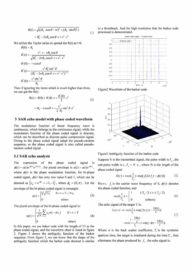
Figure3 Ambiguity function of the barker code
2R(t)T--C . 2R(t)
.rect( ) .expl) .¢(T - --)]Tp C
Where a is the back scatter coefficient, I: is the synthetic
aperture time, the target is irradiated during the time I: , then
eliminates the phase produced by fc, the echo signal is:
(7)
(others)
Suppose S is the transmitted signal, the pulse width is Tp , the
sub-pulse width is T1 ,Tp == N . T1 , where N is the length of the
phase coded signal
S(T) = rect('!-). exp(j(2Jl"fcT + ¢(T))) (5)Tp
Where, fc is the carrier wave frequency of S, ¢(T) denotes
the phase coded function, and
T { 1rect(-) =Tp 0
The echo signal of the target Tis:
S,. (t, T) =0". rect(~). exp[j21r.f: (T _ 2R(t))]r: C
The expression of the phase coded signal IS
¢(t) =a(t)eJ¢(f)eJ27rfcf , the plural envelope is u(t) == a(t)ej¢(t) ,
where ¢(t) is the phase modulation function, for bi-phase
coded signal, ¢(t) has only two value 0 and 1, which can be
denoted as {ck =ej,p. =+l,-l}, where fA ={O,7l"}. Let the
envelope of the bi-phase coded signal is rectangle.
{II~Nil 0 < t < T == N i 1
a(t)==o others
The plural envelope of the bi-phase coded signal is:
{
I N-l
_ r;:; ~>kv(t - kt; ) 0 < t < Tu(t) - "N k=O (4)
o others
In this paper, we use baker code with the length of 13 as thephase coded signal, and the waveform chart is listed in figure2. Figure 3 shows the ambiguity function of the barkersequence. From figure 3, we can know that the shape of theambiguity function which the barker code showed is similar
3.1 SAR echo analysis
Raw SAR Echo Data
Due to the transmitted signal is the phase coded signal, so theperformance of the range direction signal dissatisfied theproperty of the linear frequency wave, therefore, the matchingfilter should have the coherence with the phase coded signalin order to meet the pulse compression correctly.Based on the echo signal model, we process the echo datathrough RD algorithm in order to gain the image of the target.The flowchart of the RD algorithm is described in figure 4.
S,(t, r) =(J". rect(~).exp[- j 47Z" R(t)]r: R
2R(t)t - ----c . 2R(t)
.rect( ). exp[j ·¢J(r---)]Tp C
3.2 Compression process
(8)
Parameters Value
Wavelength (m) 0.008
Sub-pulse width (f.1 s) 0.65
Wideband (MHz) 20
Antenna length (m) 2
Pulse Repetition Frequency (Hz) 3625
Sampling frequency (MHz) 40
Velocity (m/s) 1200
Slant range distance (km) 10
Table 1. Main simulation parameters
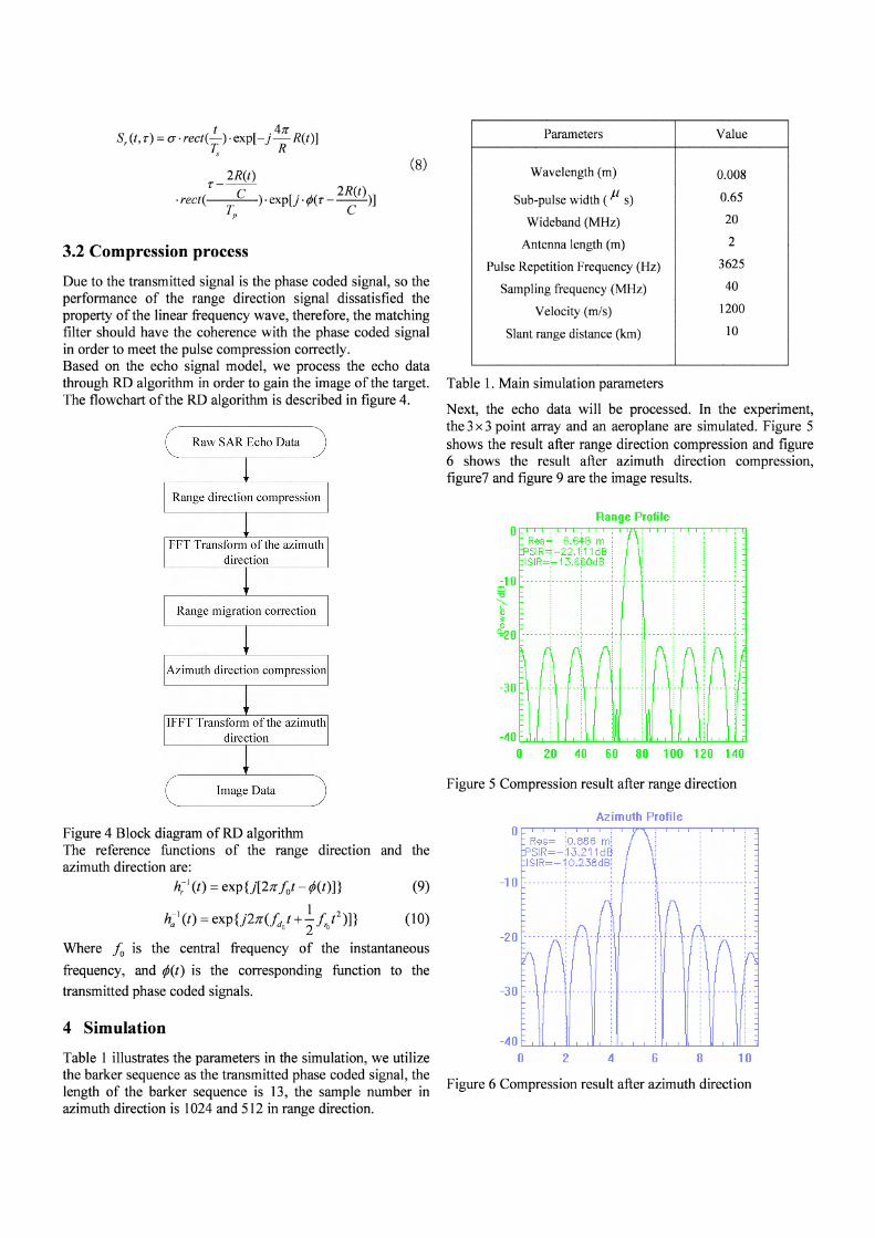
Next, the echo data will be processed. In the experiment,the 3x 3 point array and an aeroplane are simulated. Figure 5shows the result after range direction compression and figure6 shows the result after azimuth direction compression,figure? and figure 9 are the image results.
Range direction compression
FFT Transform of the azimuthdirection
Range migration correction
Azimuth direction compression
IFFT Transform of the azimuthdirection
Image Data Figure 5 Compression result after range direction
Azimuth Profile
Figure 6 Compression result after azimuth direction
10B62
-40 '----'-....I...I....-.L.-.....1.l----L...-...L..&.....J..----:........L...............----J....-.....:........L'----'-....LL.....-.:...........a.----L...-.J....L..L.....----LI
o
4 Simulation
Table 1 illustrates the parameters in the simulation, we utilizethe barker sequence as the transmitted phase coded signal, thelength of the barker sequence is 13, the sample number inazimuth direction is 1024 and 512 in range direction.
Figure 4 Block diagram ofRD algorithmThe reference functions of the range direction and theazimuth direction are:
h;l (t) =exp{j[2Jrlot - ¢(t)]} (9)
h:1(t ) = exp{j27T(fd t+~ f,f)]} (10)o 2 0
Where fa is the central frequency of the instantaneous
frequency, and ¢(t) is the corresponding function to the
transmitted phase coded signals.
20
30
5 Conclusion
[1] Chen Haizhong and Zhu Weiqiang. "Analysis of TheIntrapulse Characteristic of Phase coded Radar Signal"[J].Shipboard Electronic Countermeasure, Vol.29, No.2, April,2006[2] Eaves J L,Reedy E. The Principles of Modem Radar[ M].National Defence Industry Press, Beijing,1989[3] Guo caihong, Chen jie, Sun Yumeng, Sun Bing and ZhouYinqing. "Air to air Missile Borne SAR Imaging Processingof Forward-Looking Squinted Data" [J]. Journal of Astronautics, vol.27, No.5, September 2006[4] Ian G. Cumming and Frank H. Wong. Digital Processingof Synthetic Aperture Radar Data Algorithms and Implementation [M]. Publishing house of Electronics Industry, Beijing,2007[5] M.I.Skolnik. Radar Handbook [M].Publishing house ofElectronics Industry, Beijing,2003[6] Sun Dongyan, Tao Jianfeng and Fu Quanxi. "The DopplerCompensation for Phase coded Waveforms" [J].Journal of airforce engineering university (National Science Edition),l(l),2000[7] Sun Yumeng, Chen Jie, Guo Caihong, Sun Bing and ZhouYinqing "The Advanced Simulation System for MMWImaging Radar Seeker on board Air-to-air"[J].2006 8th
International Conference on Signal Processing Proceedings.[8] Zhang Guanjie, Guo Min, Bao Yongjie. "Silence trackingradar" [J]. CIE International Conference of Radar Processings,pp.125-128.2001
This work was partly supported by Aviation Science Foundationof China (Grant No.20060151006) and supported in part by theProgram for New Century Excellent Talents in University, Ministryof Education, China (Grant No. NCET-06-0166).
Acknowledgements
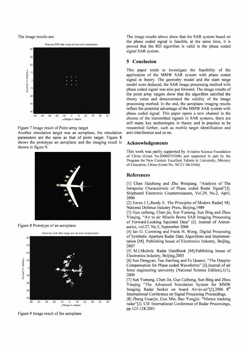
The image results above show that the SAR system based onthe phase coded signal is feasible, at the same time, it isproved that the RD algorithm is valid in the phase codedsignal SAR system.
References
This paper tends to investigate the feasibility of theapplication of the MMW SAR system with phase codedsignal in theory. The geometry model and the slant rangemodel were deduced, the SAR image processing method withphase coded signal was also put forward. The image results ofthe point array targets show that the algorithm satisfied thetheory value and demonstrated the validity of the imageprocessing method. In the end, the aeroplane imaging resultsreflect the potential advantage of the MMW SAR system withphase coded signal. This paper opens a new channel in thechoose of the transmitted signals in SAR systems, there arestill many key technologies in theory and in practice to beresearched further, such as mobile target identification andanti-interference and so on.
Stripmap SAR after range and azimuth compression
-30
-20
20
-40
-40 -30 -20 -10 0 10 20 30 40 50~Range in meters
Stripmap SAR after range and azimuth compression
-40 -30 -20 -10 0 10 20 30 40 50
~Range in meters
~ -10~Q)
E.s..c::5.§ 10N
o::t:
30
-20
-30
-40
~ -10Q)
~.s..c::5.S 10Nq::
Figure 9 Image result of the aeroplane
The image results are:
Figure 8 Prototype of an aeroplane
Figure 7 Image result of Point array targetAnother simulation target was an aeroplane, the simulationparameters are the same as that of point target. Figure 8shows the prototype an aeroplane and the imaging result isshown in figure 9.