Embed Size (px)
Citation preview

OPERATOR’S MANUAL
For use with machines having Code Numbers 10219, 10219CV, 10220, 10220CV, 10628, 10629,10872 and 10910
IM553-CJuly, 2003
Safety Depends on YouLincoln arc welding and cuttingequipment is designed and builtwith safety in mind. However, youroverall safety can be increased byproper installation ... and thought-ful operation on your part. DONOT INSTALL, OPERATE ORREPAIR THIS EQUIPMENTWITHOUT READING THISMANUAL AND THE SAFETYPRECAUTIONS CONTAINEDTHROUGHOUT. And, mostimportantly, think before you actand be careful.
CLASSIC™ IIDC ARC WELDER WITH DEUTZ F3L-1011F ENGINE
• Sales and Service through Subsidiaries and Distributors Worldwide •
Cleveland, Ohio 44117-1199 U.S.A. TEL: 216.481.8100 FAX: 216.486.1751 WEB SITE: www.lincolnelectric.com
• World's Leader in Welding and Cutting Products •
Copyright © 2003 Lincoln Global Inc.

CLASSIC II DEUTZ
FOR ENGINEpowered equipment.
1.a. Turn the engine off before troubleshooting and maintenancework unless the maintenance work requires it to be running.
____________________________________________________1.b.Operate engines in open, well-ventilated
areas or vent the engine exhaust fumes outdoors.
____________________________________________________1.c. Do not add the fuel near an open flame
welding arc or when the engine is running.Stop the engine and allow it to cool beforerefueling to prevent spilled fuel from vaporiz-ing on contact with hot engine parts andigniting. Do not spill fuel when filling tank. Iffuel is spilled, wipe it up and do not startengine until fumes have been eliminated.
____________________________________________________1.d. Keep all equipment safety guards, coversand devices in posi-
tion and in good repair.Keep hands, hair, clothing and toolsaway from V-belts, gears, fans and all other moving partswhen starting, operating or repairing equipment.
____________________________________________________
1.e. In some cases it may be necessary to remove safetyguards to perform required maintenance. Removeguards only when necessary and replace them when themaintenance requiring their removal is complete.Always use the greatest care when working near movingparts.
___________________________________________________1.f. Do not put your hands near the engine fan.
Do not attempt to override the governor oridler by pushing on the throttle control rodswhile the engine is running.
___________________________________________________1.g. To prevent accidentally starting gasoline engines while
turning the engine or welding generator during maintenancework, disconnect the spark plug wires, distributor cap ormagneto wire as appropriate.
iSAFETYi
ARC WELDING CAN BE HAZARDOUS. PROTECT YOURSELF AND OTHERS FROM POSSIBLE SERIOUS INJURY OR DEATH.KEEP CHILDREN AWAY. PACEMAKER WEARERS SHOULD CONSULT WITH THEIR DOCTOR BEFORE OPERATING.
Read and understand the following safety highlights. For additional safety information, it is strongly recommended that youpurchase a copy of “Safety in Welding & Cutting - ANSI Standard Z49.1” from the American Welding Society, P.O. Box351040, Miami, Florida 33135 or CSA Standard W117.2-1974. A Free copy of “Arc Welding Safety” booklet E205 is availablefrom the Lincoln Electric Company, 22801 St. Clair Avenue, Cleveland, Ohio 44117-1199.
BE SURE THAT ALL INSTALLATION, OPERATION, MAINTENANCE AND REPAIR PROCEDURES AREPERFORMED ONLY BY QUALIFIED INDIVIDUALS.
WARNING
Mar ‘95
ELECTRIC AND MAGNETIC FIELDSmay be dangerous
2.a. Electric current flowing through any conductor causes localized Electric and Magnetic Fields (EMF). Welding current creates EMF fields around welding cables and welding machines
2.b. EMF fields may interfere with some pacemakers, andwelders having a pacemaker should consult their physicianbefore welding.
2.c. Exposure to EMF fields in welding may have other healtheffects which are now not known.
2.d. All welders should use the following procedures in order tominimize exposure to EMF fields from the welding circuit:
2.d.1. Route the electrode and work cables together - Securethem with tape when possible.
2.d.2. Never coil the electrode lead around your body.
2.d.3. Do not place your body between the electrode andwork cables. If the electrode cable is on your right side, the work cable should also be on your right side.
2.d.4. Connect the work cable to the workpiece as close aspossible to the area being welded.
2.d.5. Do not work next to welding power source.
1.h. To avoid scalding, do not remove theradiator pressure cap when the engine ishot.
CALIFORNIA PROPOSITION 65 WARNINGS
Diesel engine exhaust and some of its constituentsare known to the State of California to cause can-cer, birth defects, and other reproductive harm.
The engine exhaust from this product containschemicals known to the State of California to causecancer, birth defects, or other reproductive harm.
The Above For Diesel Engines The Above For Gasoline Engines

CLASSIC II DEUTZ
iiSAFETYii
ARC RAYS can burn.4.a. Use a shield with the proper filter and cover
plates to protect your eyes from sparks andthe rays of the arc when welding or observingopen arc welding. Headshield and filter lensshould conform to ANSI Z87. I standards.
4.b. Use suitable clothing made from durable flame-resistantmaterial to protect your skin and that of your helpers fromthe arc rays.
4.c. Protect other nearby personnel with suitable, non-flammablescreening and/or warn them not to watch the arc nor exposethemselves to the arc rays or to hot spatter or metal.
ELECTRIC SHOCK cankill.3.a. The electrode and work (or ground) circuits
are electrically “hot” when the welder is on.Do not touch these “hot” parts with your bareskin or wet clothing. Wear dry, hole-free
gloves to insulate hands.
3.b. Insulate yourself from work and ground using dry insulation.Make certain the insulation is large enough to cover your fullarea of physical contact with work and ground.
In addition to the normal safety precautions, if weldingmust be performed under electrically hazardousconditions (in damp locations or while wearing wetclothing; on metal structures such as floors, gratings orscaffolds; when in cramped positions such as sitting,kneeling or lying, if there is a high risk of unavoidable oraccidental contact with the workpiece or ground) usethe following equipment:
• Semiautomatic DC Constant Voltage (Wire) Welder.• DC Manual (Stick) Welder.• AC Welder with Reduced Voltage Control.
3.c. In semiautomatic or automatic wire welding, the electrode,electrode reel, welding head, nozzle or semiautomaticwelding gun are also electrically “hot”.
3.d. Always be sure the work cable makes a good electricalconnection with the metal being welded. The connectionshould be as close as possible to the area being welded.
3.e. Ground the work or metal to be welded to a good electrical(earth) ground.
3.f. Maintain the electrode holder, work clamp, welding cable andwelding machine in good, safe operating condition. Replacedamaged insulation.
3.g. Never dip the electrode in water for cooling.
3.h. Never simultaneously touch electrically “hot” parts ofelectrode holders connected to two welders because voltagebetween the two can be the total of the open circuit voltageof both welders.
3.i. When working above floor level, use a safety belt to protectyourself from a fall should you get a shock.
3.j. Also see Items 6.c. and 8.
FUMES AND GASEScan be dangerous.5.a. Welding may produce fumes and gases
hazardous to health. Avoid breathing thesefumes and gases.When welding, keepyour head out of the fume. Use enoughventilation and/or exhaust at the arc to keep
fumes and gases away from the breathing zone. Whenwelding with electrodes which require specialventilation such as stainless or hard facing (seeinstructions on container or MSDS) or on lead orcadmium plated steel and other metals or coatingswhich produce highly toxic fumes, keep exposure aslow as possible and below Threshold Limit Values (TLV)using local exhaust or mechanical ventilation. Inconfined spaces or in some circumstances, outdoors, arespirator may be required. Additional precautions arealso required when welding on galvanized steel.
5.b. Do not weld in locations near chlorinated hydrocarbon vaporscoming from degreasing, cleaning or spraying operations.
The heat and rays of the arc can react with solvent vapors toform phosgene, a highly toxic gas, and other irritating products.
5.c. Shielding gases used for arc welding can displace air andcause injury or death. Always use enough ventilation,especially in confined areas, to insure breathing air is safe.
5.d. Read and understand the manufacturer’s instructions for thisequipment and the consumables to be used, including thematerial safety data sheet (MSDS) and follow youremployer’s safety practices. MSDS forms are available fromyour welding distributor or from the manufacturer.
5.e. Also see item 1.b. Mar ‘95

CLASSIC II DEUTZ
FOR ELECTRICALLYpowered equipment.
8.a. Turn off input power using the disconnectswitch at the fuse box before working onthe equipment.
8.b. Install equipment in accordance with the U.S. NationalElectrical Code, all local codes and the manufacturer’srecommendations.
8.c. Ground the equipment in accordance with the U.S. NationalElectrical Code and the manufacturer’s recommendations.
CYLINDER may explodeif damaged.7.a. Use only compressed gas cylinders
containing the correct shielding gas for theprocess used and properly operatingregulators designed for the gas and
pressure used. All hoses, fittings, etc. should be suitable forthe application and maintained in good condition.
7.b. Always keep cylinders in an upright position securelychained to an undercarriage or fixed support.
7.c. Cylinders should be located:• Away from areas where they may be struck or subjected tophysical damage.
• A safe distance from arc welding or cutting operations andany other source of heat, sparks, or flame.
7.d. Never allow the electrode, electrode holder or any otherelectrically “hot” parts to touch a cylinder.
7.e. Keep your head and face away from the cylinder valve outletwhen opening the cylinder valve.
7.f. Valve protection caps should always be in place and handtight except when the cylinder is in use or connected foruse.
7.g. Read and follow the instructions on compressed gascylinders, associated equipment, and CGA publication P-l,“Precautions for Safe Handling of Compressed Gases inCylinders,” available from the Compressed Gas Association1235 Jefferson Davis Highway, Arlington, VA 22202.
iiiSAFETYiii
Mar ‘95
WELDING SPARKS cancause fire or explosion.6.a. Remove fire hazards from the welding area.
If this is not possible, cover them to preventthe welding sparks from starting a fire.Remember that welding sparks and hot
materials from welding can easily go through small cracksand openings to adjacent areas. Avoid welding nearhydraulic lines. Have a fire extinguisher readily available.
6.b. Where compressed gases are to be used at the job site,special precautions should be used to prevent hazardoussituations. Refer to “Safety in Welding and Cutting” (ANSIStandard Z49.1) and the operating information for theequipment being used.
6.c. When not welding, make certain no part of the electrodecircuit is touching the work or ground. Accidental contactcan cause overheating and create a fire hazard.
6.d. Do not heat, cut or weld tanks, drums or containers until theproper steps have been taken to insure that such procedureswill not cause flammable or toxic vapors from substancesinside. They can cause an explosion even though they havebeen “cleaned”. For information, purchase “RecommendedSafe Practices for the Preparation for Welding and Cutting ofContainers and Piping That Have Held HazardousSubstances”, AWS F4.1 from the American Welding Society(see address above).
6.e. Vent hollow castings or containers before heating, cutting orwelding. They may explode.
6.f. Sparks and spatter are thrown from the welding arc. Wear oilfree protective garments such as leather gloves, heavy shirt,cuffless trousers, high shoes and a cap over your hair. Wearear plugs when welding out of position or in confined places.Always wear safety glasses with side shields when in awelding area.
6.g. Connect the work cable to the work as close to the weldingarea as practical. Work cables connected to the buildingframework or other locations away from the welding areaincrease the possibility of the welding current passingthrough lifting chains, crane cables or other alternate cir-cuits. This can create fire hazards or overheat lifting chainsor cables until they fail.
6.h. Also see item 1.c.

CLASSIC II DEUTZ
ivSAFETYiv
Mar. ‘93
PRÉCAUTIONS DE SÛRETÉPour votre propre protection lire et observer toutes les instruc-tions et les précautions de sûreté specifiques qui parraissentdans ce manuel aussi bien que les précautions de sûretégénérales suivantes:
Sûreté Pour Soudage A L’Arc1. Protegez-vous contre la secousse électrique:
a. Les circuits à l’électrode et à la piéce sont sous tensionquand la machine à souder est en marche. Eviter toujourstout contact entre les parties sous tension et la peau nueou les vétements mouillés. Porter des gants secs et sanstrous pour isoler les mains.
b. Faire trés attention de bien s’isoler de la masse quand onsoude dans des endroits humides, ou sur un planchermetallique ou des grilles metalliques, principalement dans
les positions assis ou couché pour lesquelles unegrande partie du corps peut être en contact avec lamasse.
c. Maintenir le porte-électrode, la pince de masse, le câblede soudage et la machine à souder en bon et sûr étatdefonctionnement.
d.Ne jamais plonger le porte-électrode dans l’eau pour lerefroidir.
e. Ne jamais toucher simultanément les parties sous tensiondes porte-électrodes connectés à deux machines à soud-er parce que la tension entre les deux pinces peut être letotal de la tension à vide des deux machines.
f. Si on utilise la machine à souder comme une source decourant pour soudage semi-automatique, ces precautionspour le porte-électrode s’applicuent aussi au pistolet desoudage.
2. Dans le cas de travail au dessus du niveau du sol, se pro-téger contre les chutes dans le cas ou on recoit un choc. Nejamais enrouler le câble-électrode autour de n’importe quellepartie du corps.
3. Un coup d’arc peut être plus sévère qu’un coup de soliel,donc:
a. Utiliser un bon masque avec un verre filtrant appropriéainsi qu’un verre blanc afin de se protéger les yeux durayonnement de l’arc et des projections quand on soudeou quand on regarde l’arc.
b. Porter des vêtements convenables afin de protéger lapeau de soudeur et des aides contre le rayonnement del‘arc.
c. Protéger l’autre personnel travaillant à proximité ausoudage à l’aide d’écrans appropriés et non-inflamma-bles.
4. Des gouttes de laitier en fusion sont émises de l’arc desoudage. Se protéger avec des vêtements de protectionlibres de l’huile, tels que les gants en cuir, chemise épaisse,pantalons sans revers, et chaussures montantes.
5. Toujours porter des lunettes de sécurité dans la zone desoudage. Utiliser des lunettes avec écrans lateraux dans leszones où l’on pique le laitier.
6. Eloigner les matériaux inflammables ou les recouvrir afin deprévenir tout risque d’incendie dû aux étincelles.
7. Quand on ne soude pas, poser la pince à une endroit isolé dela masse. Un court-circuit accidental peut provoquer unéchauffement et un risque d’incendie.
8. S’assurer que la masse est connectée le plus prés possiblede la zone de travail qu’il est pratique de le faire. Si on placela masse sur la charpente de la construction ou d’autresendroits éloignés de la zone de travail, on augmente le risquede voir passer le courant de soudage par les chaines de lev-age, câbles de grue, ou autres circuits. Cela peut provoquerdes risques d’incendie ou d’echauffement des chaines et descâbles jusqu’à ce qu’ils se rompent.
9. Assurer une ventilation suffisante dans la zone de soudage.Ceci est particuliérement important pour le soudage de tôlesgalvanisées plombées, ou cadmiées ou tout autre métal quiproduit des fumeés toxiques.
10. Ne pas souder en présence de vapeurs de chlore provenantd’opérations de dégraissage, nettoyage ou pistolage. Lachaleur ou les rayons de l’arc peuvent réagir avec lesvapeurs du solvant pour produire du phosgéne (gas forte-ment toxique) ou autres produits irritants.
11. Pour obtenir de plus amples renseignements sur la sûreté,voir le code “Code for safety in welding and cutting” CSAStandard W 117.2-1974.
PRÉCAUTIONS DE SÛRETÉ POURLES MACHINES À SOUDER ÀTRANSFORMATEUR ET ÀREDRESSEUR
1. Relier à la terre le chassis du poste conformement au codede l’électricité et aux recommendations du fabricant. Le dis-positif de montage ou la piece à souder doit être branché àune bonne mise à la terre.
2. Autant que possible, I’installation et l’entretien du posteseront effectués par un électricien qualifié.
3. Avant de faires des travaux à l’ interieur de poste, ladebrancher à l’interrupteur à la boite de fusibles.
4. Garder tous les couvercles et dispositifs de sûreté à leurplace.

vv
Thank You for selecting a QUALITY product by Lincoln Electric. We want youto take pride in operating this Lincoln Electric Company product••• as much pride as we have in bringing this product to you!
Read this Operators Manual completely before attempting to use this equipment. Save this manual and keep ithandy for quick reference. Pay particular attention to the safety instructions we have provided for your protection.The level of seriousness to be applied to each is explained below:
WARNINGThis statement appears where the information must be followed exactly to avoid serious personal injury orloss of life.
This statement appears where the information must be followed to avoid minor personal injury or damage tothis equipment.
CAUTION
Please Examine Carton and Equipment For Damage ImmediatelyWhen this equipment is shipped, title passes to the purchaser upon receipt by the carrier. Consequently, Claimsfor material damaged in shipment must be made by the purchaser against the transportation company at thetime the shipment is received.
Please record your equipment identification information below for future reference. This information can befound on your machine nameplate.
Product _________________________________________________________________________________
Model Number ___________________________________________________________________________
Code Number or Date Code_________________________________________________________________
Serial Number____________________________________________________________________________
Date Purchased___________________________________________________________________________
Where Purchased_________________________________________________________________________
Whenever you request replacement parts or information on this equipment, always supply the information youhave recorded above. The code number is especially important when identifying the correct replacement parts.
On-Line Product Registration
- Register your machine with Lincoln Electric either via fax or over the Internet.
• For faxing: Complete the form on the back of the warranty statement included in the literature packetaccompanying this machine and fax the form per the instructions printed on it.
• For On-Line Registration: Go to our WEB SITE at www.lincolnelectric.com. Choose “Quick Links” and then“Product Registration”. Please complete the form and submit your registration.
vivi
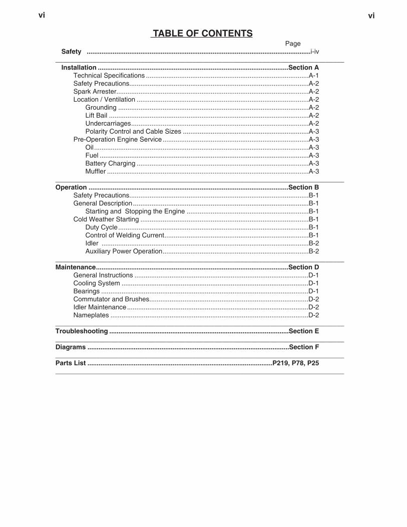
TABLE OF CONTENTSPage
Safety .........................................................................................................................i-iv______________________________________________________________________________
Installation .......................................................................................................Section ATechnical Specifications ........................................................................................A-1Safety Precautions.................................................................................................A-2Spark Arrester........................................................................................................A-2Location / Ventilation .............................................................................................A-2
Grounding .......................................................................................................A-2Lift Bail ............................................................................................................A-2Undercarriages................................................................................................A-2Polarity Control and Cable Sizes ....................................................................A-3
Pre-Operation Engine Service ...............................................................................A-3Oil ....................................................................................................................A-3Fuel .................................................................................................................A-3Battery Charging .............................................................................................A-3Muffler .............................................................................................................A-3
______________________________________________________________________________Operation ............................................................................................................Section B
Safety Precautions.................................................................................................B-1General Description ...............................................................................................B-1
Starting and Stopping the Engine ..................................................................B-1Cold Weather Starting ...........................................................................................B-1
Duty Cycle.......................................................................................................B-1Control of Welding Current..............................................................................B-1Idler ................................................................................................................B-2Auxiliary Power Operation...............................................................................B-2
______________________________________________________________________________Maintenance........................................................................................................Section D
General Instructions ..............................................................................................D-1Cooling System .....................................................................................................D-1Bearings ................................................................................................................D-1Commutator and Brushes......................................................................................D-2Idler Maintenance..................................................................................................D-2Nameplates ...........................................................................................................D-2
______________________________________________________________________________Troubleshooting .................................................................................................Section E______________________________________________________________________________Diagrams .............................................................................................................Section F______________________________________________________________________________Parts List ....................................................................................................P219, P78, P25______________________________________________________________________________

A-1
CLASSIC II DEUTZ
A-1
TECHNICAL SPECIFICATIONS - CLASSIC II DEUTZ K1406-( )
Make/Model Description Speed (RPM) Bore x Stroke Starting CapacitiesSystem
Deutz 3 cylinder High Idle 1800 3.58” x 4.13 12VDC battery Fuel: 15gal.F3L 1011F 28.5 HP Low Idle 1350 (91mm x 105mm) & Starter 57 LDiesel Engine @ 1700 RPM Full Load 1725SA-250 Oil: 6.3 Qts.
6.0 L
INPUT - DIESEL ENGINE
RATED OUTPUT - WELDER
HEIGHT WIDTH DEPTH WEIGHT
42.94 in. 24 in. 60 in. 1340 lbs.(608 kg)
(1040 mm) (610 mm) (1524 mm)
OUTPUT - WELDER AND GENERATOR
Duty Cycle Constant Current Volts at Rated Amps
Current Range NEMA Output Rating Auxiliary Power
40-325 Amps 250 amps 30 volts 115/250 VAC@60% Duty Cycle 3kVA
60% Duty Cycle
PHYSICAL DIMENSIONS
40% 300 amps (DC ) 32 volts60% 250 amps (DC ) 30 volts100% 200 amps (DC ) 28 volts
INSTALLATION

A-2
CLASSIC II DEUTZ
A-2
SAFETY PRECAUTIONS
Exhaust Spark Arrester
Some federal, state or local laws may require thatdiesel engines be equipped with exhaust sparkarresters when they are operated in certain locationswhere unarrested sparks may present a fire hazard.The standard mufflers included with these welders donot qualify as spark arresters. When required by localregulations, install the optional spark arrester kit.Spark arresters must be installed and properly main-tained, instructions are included in the kit.
Use of an incorrect arrester may lead to engine damageor performance loss.-----------------------------------------------------------Location/VentilationAlways operate the welder with the doors closed.Leaving the doors open changes the designed air flowand may cause overheating.
The welder should be located to provide an unrestrict-ed flow of clean, cool air. Also, locate the welder sothat engine exhaust fumes are properly vented to anoutside area.
DO NOT MOUNT OVER COMBUSTIBLE SUR-FACES.Where there is a combustible surface directly understationary or fixed electrical equipment, the surfaceshall be covered with a steel plate at least.06”(1.6mm) thick, which shall extend not more than5.90”(150mm) beyond the equipment on all sides.------------------------------------------------------------------------Grounding
According to the United States National ElectricalCode, the frame of this portable generator is notrequired to be grounded and is permitted to serve asthe grounding means for cord connected equipmentplugged into its receptacle.
Some state, local, or other codes or unusual operatingcircumstances may require the machine frame to begrounded. It is recommended that you determine theextent to which such requirements may apply to yourparticular situation and follow them explicitly. Amachine grounding stud marked with the symbolis provided on the welding generator frame foot. (If anolder portable welder does not have a grounding stud,connect the ground wire to an unpainted frame screwor bolt.) In general, if the machine is to be grounded,it should be connected with a #8 or larger copper wireto a solid earth ground such as a metal water pipegoing into the ground for at least ten feet and havingno insulated joints, or to the metal framework of abuilding which has been effectively grounded. TheU.S. National Electrical Code lists a number of alter-nate means of grounding electrical equipment.
Lift Bail
A lift bail is provided for lifting with a hoist.
Do not attempt to use this equipment until youhave thoroughly read the engine manufacturer’smanual supplied with your welder. It includesimportant safety precautions, detailed enginestarting, operating and maintenance instructions,and parts lists.------------------------------------------------------------------------
ELECTRIC SHOCK can kill.• Do not touch electrically live parts or
electrode with skin or wet clothing.• Insulate yourself from work and
ground• Always wear dry insulating gloves.
------------------------------------------------------------------------ENGINE EXHAUST can kill.• Use in open, well ventilated areas or
vent exhaust outside.
------------------------------------------------------------------------MOVING PARTS can injure.• Do not operate with doors open or
guards off.• Stop engine before servicing.• Keep away from moving parts.
------------------------------------------------------------------------
See additional warning information at thefront of this operator’s manual.
-----------------------------------------------------------
WARNING
CAUTION FALLING EQUIPMENT can causeinjury.• Do not lift this machine using lift bale
if it is equipped with a heavy accesso-ry such as a trailer or gas cylinder.
• Lift only with equipment of adequatelifting capacity.
• Be sure machine is stable when lifting.----------------------------------------------------------------------
WARNING
INSTALLATION
CAUTION

A-3
CLASSIC II DEUTZ
A-3
Undercarriages
If the user adapts a non-Lincoln undercarriage, hemust assume responsibility that the method of attach-ment and usage does not result in a safety hazard nordamage the welding equipment. Some of the factorsto be considered are as follows:
1. Design capacity of undercarriage vs. weight ofLincoln equipment and likely additional attach-ments.
2. Proper support of, and attachment to, the base ofthe welding equipment so there will be no unduestress to the framework.
3. Proper placement of the equipment on the under-carriage to ensure stability side to side and front toback when being moved and when standing byitself while being operated or serviced.
4. Typical conditions of use, i.e., travel speed, rough-ness of surface on which the undercarriage will beoperated; environmental conditions, likely mainte-nance.
5. Conformance with federal, state and locallaws.Consult applicable federal, state and locallaws regarding specific requirements for use onpublic highways.
Polarity Control and Cable Sizes
With the engine off, route the electrode and workcables through the strain relief bracket on the baseand connect to the studs located below the fuel tankmounting rail. (See size recommendations below.)For positive polarity, connect the electrode cable tothe terminal marked “Positive (+)”. For Negativepolarity, connect the electrode cable to the “Negative(-)” stud. These connections should be checked peri-odically and tightened if necessary.
When welding at a considerable distance from the
welder, be sure you use ample size welding cables. PRE-OPERATION SERVICEREAD the engine operating and maintenance instruc-tions supplied with this machine.-------------------------------------------------------------------
RECOMMENDED COPPER CABLE SIZESCables Sizes for Combined Lengthof Electrode Plus Work Cable
Amps Duty Cycle Up to 200 ft. 200 to 250 ft.
200 100% 1 1/0250 60% 1 1/0300 40% 1/0 2/0
INSTALLATION OilThis unit is supplied from the factory with the enginecrankcase filled with a high quality SAE 10W/30 oil.This oil should be acceptable for most typical ambienttemperatures. Consult the engine operation manualfor specific engine manufacturer's recommendations.Upon receipt of the welder, check the engine dipstickto be sure the oil is at the “full” mark. DO NOT overfill.Note: A optional Oil Drain Kit is available for thisengine. (Order K1604-1)
NOTE: This unit is equipped with an EngineProtection Package, an internal kill switch willshut down the engine if the oil pressure dropsbelow a minimum operating specification, or if theoil temperature reaches an excessive level.
FuelFill the fuel tank with the grade of fuel recommendedin the Engine Operator’s manual. Make sure the fuelvalve on the sediment bowl is in the open position.

A-4
CLASSIC II DEUTZ
A-4
Battery Charging
The Classic II is equipped with a wet charged battery.The charging current is automatically regulated whenthe battery is low (after starting the engine) to a tricklecurrent when the battery is fully charged.
When replacing, jumping or otherwise connecting thebattery to the battery cables, the proper polarity mustbe observed. This system is NEGATIVE GROUND.
Muffler
This welder is supplied with an adjustable rain cap forthe muffler. Install the rain cap using the clamp pro-vided with the outlet facing away from the direction inwhich this unit will be transported. This will minimizethe amount of water and debris which could enter themuffler during transportation.
GASES FROM BATTERY can explode.• Keep sparks, flame and cigarettes
away.
BATTERY ACID can burn eyes andskin.• Wear gloves and eye protection and
be careful when boosting, charging orworking near battery.
To prevent EXPLOSION when:a) Installing a new battery - disconnect the
negative cable from the old battery first and connect the negative cable to the new battery last.
b) Connecting a battery charger - remove the battery from the welder by disconnecting the negative cable first, then the positive cable andbattery clamp. When reinstalling, connect the negative cable last.
c) Using a booster - connect the positive lead to the battery first, then connect the negative lead to the ground lead on the base.
To prevent ELECTRICAL DAMAGE when:a) Installing a new battery.b) Using a booster.
Use correct polarity - Negative Ground.
To prevent BATTERY DISCHARGE, if you have an ignition switch, turn it off when engine is notrunning.
• To prevent BATTERY BUCKLING, tighten nuts on battery clamp until snug.
------------------------------------------------------------------------
WARNING

B-1
CLASSIC II DEUTZ
B-1
SAFETY PRECAUTIONS
Do not attempt to use this equipment until youhave thoroughly read the engine manufacturer’smanual supplied with your welder. It includesimportant safety precautions, detailed enginestarting, operating and maintenance instructions,and parts lists.------------------------------------------------------------------------
ELECTRIC SHOCK can kill.• Do not touch electrically live parts or
electrode with skin or wet clothing.• Insulate yourself from work and
ground• Always wear dry insulating gloves.
------------------------------------------------------------------------ENGINE EXHAUST can kill.• Use in open, well ventilated areas or
vent exhaust outside.
------------------------------------------------------------------------MOVING PARTS can injure.• Do not operate with doors open or
guards off.• Stop engine before servicing.• Keep away from moving parts.
------------------------------------------------------------------------See additional warning information at thefront of this operator’s manual.
-----------------------------------------------------------
WARNING
GENERAL DESCRIPTION
The Classic™ II is a heavy duty engine driven DC arcwelding power source capable of providing constantcurrent output for stick welding or DC TIG welding.The Classic II is wound with all copper coils and isconfigured in a new shorter case with no exciter stick-out and setup for one side service. With the additionof the optional Wire Feed Module on models K1406-3and K1406-4 the Classic II will provide constant volt-age output for running the LN-7 or LN-25.
This unit uses the Deutz F3L-1011F industrial aircooled diesel engine.
Starting the Deutz F3L-1011F EngineTo start the engine, place the “IDLER” switch in the “HIGH” position,the “IGNITION” switch in the “ON” position and then press the“START” button. When the engine starts running, observe the oilpressure. If no pressure shows within 30 seconds, stop the engineand consult the engine operating manual. To stop the engine, placethe “IGNITION” switch in the “OFF” position. If the engine protectionwarning light comes on during cranking or after start up, the “igni-tion” switch must be placed in the “OFF” position to reset the engineprotection system.
When an engine is started for the first time, some of the oil will beneeded to fill the passages of the lubricating system. Therefore, oninitial starting, run the engine for about five minutes and then stopthe engine and recheck the oil. If the level is down, fill to the fullmark again. The engine controls were properly set at the factoryand should require no adjusting when received.
At the end of each day’s welding, drain accumulated dirt and waterfrom the sediment bowl under the fuel tank and from the fuel filterper instructions in the engine manufacturer’s operating manual.Refill the fuel tank to minimize moisture condensation in the tank.Also, running out of fuel tends to draw dirt into the fuel system.Check the crankcase oil level.
In diesel engines, if the fuel supply is cut off or runs out while thefuel pump is operating, air may be entrapped in the fuel distributionsystem. If this happens, bleeding of the fuel system should not berequired since the Deutz F3L-1011F engine is equipped with a selfpriming feature.
Cold Weather Starting
Follow the instructions on the nameplate and in the engine manualshipped with the welder. With a fully charged battery and the properweight oil, the engine should start satisfactorily even down to about0°F.
If the engine must be frequently started below 10°F, it may be desir-able to install the optional ether starter kit. Installation and operatinginstructions are included in the kit. Use ether starting only whenrequired because excessive use shortens engine life.
It is important that the Engine Manufacturer’s recommendations foroil and fuel are followed to obtain satisfactory cold weather perfor-mance. Consult the engine manual.
Duty Cycle
The NEMA output rating of the Classic II is 250 amperes at 30(1)
arc volts on a 60% duty cycle (consult SPECIFICATIONS foralternate ratings). Duty cycle is based on a ten minute period; thus,the welder can be loaded at rated output for six minutes out of everyten minute period.
(1) The Lincoln “plus output” rating at 60% duty cycle is 250amperes at 40 volts.
Control of Welding Current
DO NOT TURN THE “CURRENT RANGE SELECTOR” WHILEWELDING because the current may arc between the contactsand damage the switch.------------------------------------------------------------------------------------------The “Current Range Selector” provides five overlapping currentranges. The “Fine Current Adjustment” adjusts the current from min-imum to maximum within each range. Open circuit voltage is alsocontrolled by the “Fine Current Adjustment” permitting control of thearc characteristics.
CAUTION
OPERATION

B-2OPERATIONB-2
Auxiliary PowerThe AC auxiliary power, supplied as a standard, has arating of 3.0 kVA of 115/230V AC (60 hertz).
With the 3.0 kVA, 115/230V AC auxiliary power, one115V duplex and one 230V grounding type receptacleare provided. The circuit is protected with circuitbreakers.
The rating of 3.0 kVA permits a maximum continuouscurrent of 13 amps to be drawn from the 230 voltduplex receptacle. Or a total of 26 amps can bedrawn from the 115 volt duplex receptacle. The 115volt duplex receptacle has a configuration whichpermits 15 amps on the K1406-3 & -5 and 20 amps onthe K1406-4 &-6 to be drawn from either half. Thetotal combined load of all receptacles is not to exceed3.0 kVA.
An optional power plug kit is available. When this kitis specified, the customer is supplied with a plug foreach receptacle.
An optional GFCI 115 volt receptacle kit is also avail-able. Note that the use of this GFCI kit reduces avail-able current to 15 Amps from each half of the duplexreceptacle and to a total of 20 Amps of available 115volt power.
CLASSIC II DEUTZ
A high open circuit voltage setting provides the soft“buttering” arc with best resistance to pop-outs pre-ferred for most welding. To get this characteristic, setthe “Current Range Selector” to the lowest setting thatstill provides the current you need and set the “FineCurrent Adjustment” near maximum. For example: toobtain 175 amps and a soft arc, set the “CurrentRange Selector” to the 190-120 position and thenadjust the “Fine Current Adjustment” for 175 amps.
When a forceful “digging” arc is required, usually forvertical and overhead welding, use a higher “CurrentRange Selector” setting and lower open circuit volt-age. For example: to obtain 175 amps and a forcefularc, set the “Current Range Selector” to 240-160 posi-tion and the “Fine Current Adjustment” setting to get175 amps.
Some arc instability may be experienced with EXX10electrodes when trying to operate with long arc tech-niques at settings at the lower end of the open circuitvoltage range.
DO NOT attempt to set the “Current RangeSelector” between the five points designated onthe nameplate. These switches have a springloaded cam which almost eliminates the possibili-ty of setting this switch between the designatedpoints.------------------------------------------------------------------------
Idler OperationStart the engine with the “Idler” switch in the “High”position. Allow it to run at high idle speed for severalminutes to warm the engine. See SPECIFICATIONSfor operating speeds.
The idler is controlled by the “Idler” toggle switch onthe welder control panel. The switch has two posi-tions as follows:
1. In the “High” position, the idler is off, and theengine high speed is controlled by the governor.
2. In the “Auto” position, the idler operates as follows:a. When welding or drawing power for lights or
tools (approximately 100-150 watts minimum)from the receptacles, the engine operates atfull speed.
b. When welding ceases or the power load isturned off, a preset time delay of about 15seconds starts. This time delay cannot beadjusted.
c. If the welding or power load is not re-startedbefore the end of the time delay, the idlerreduces the engine to low idle speed.
CAUTION

D-1
CLASSIC II DEUTZ
D-1
Have qualified personnel do the maintenancework. Turn the engine off before working insidethe machine. In some cases, it may be neces-sary to remove safety guards to performrequired maintenance. Remove guards onlywhen necessary and replace them when themaintenance requiring their removal is com-plete. Always use the greatest care when work-ing near moving parts.
Do not put your hands near the engine coolingblower fan. If a problem cannot be corrected byfollowing the instructions, take the machine tothe nearest Lincoln Field Service Shop.
-----------------------------------------------------------------------ELECTRIC SHOCK can kill.• Do not touch electrically live parts or
electrode with skin or wet clothing.• Insulate yourself from work and
ground• Always wear dry insulating gloves.
------------------------------------------------------------------------ENGINE EXHAUST can kill.• Use in open, well ventilated areas or
vent exhaust outside.
------------------------------------------------------------------------MOVING PARTS can injure.• Do not operate with doors open or
guards off.• Stop engine before servicing.• Keep away from moving parts.
------------------------------------------------------------------------
See additional warning information at thefront of this operator’s manual.
-----------------------------------------------------------
WARNING
4. Inspect the air filter daily - more often in dusty condi-tions. When necessary, clean or replace. The filtershould never be removed while the engine is running.The air filter element part number is Donaldson#181050 or Nelson #70206N.
5. Drain any accumulated water from the engine fuel fil-ter/water separator daily. Change the filter every 1000hours of operation. Order Deutz fuel filter #117-4482from your local Deutz Service Center. A fuel filter ele-ment without the water separator may be used inplace of the standard element. Order Deutz #117-4696.
6. Fan belts tend to loosen after the first 50 hours ofoperation. Check engine Operation Manual andtighten if necessary. DO NOT OVER TIGHTEN.
7. Put a drop of oil on the “Current Range Selector” shaftat least once every month.
8. See the engine manufacturer’s Operation Manual fordetailed engine maintenance and troubleshootinginstructions.
COOLING SYSTEM
The Classic II is equipped with an air cooled Deutzengine. Clean the engine cooling system periodically toprevent clogging the air passages on the cylinder headsand oil cooler and overheating the engine. Consult theEngine Operation Manual. It is important that thewelder is located in a manner which will provide an unre-stricted flow of clean, cool air.
BEARINGS
This welder is equipped with a double-shielded ball bear-ing having sufficient grease to last indefinitely under nor-mal service. Where the welder is used constantly or inexcessively dirty locations, it may be necessary to addone half ounce of grease per year. A pad of grease oneinch wide, one inch long, and one inch high weighsapproximately one half ounce. Over-greasing is far worsethan insufficient greasing.
When greasing the bearings, keep all dirt out of the area.Wipe the fittings completely clean and use clean equip-ment. More bearing failures are caused by dirt introducedduring greasing than from insufficient grease.
GENERAL INSTRUCTIONS1. Blow out the welder and controls with an air hose
at least once every two months. In particularlydirty locations, this cleaning may be necessaryonce a week. Use low pressure air to avoid drivingdirt into the insulation.
2. ”Current Range Selector” contacts should not begreased. To keep the contacts clean, rotate thecurrent control through its entire range frequently.Good practice is to turn the handle from maximumto minimum setting twice each morning beforestarting to weld.
3. Change the crankcase oil and oil filter after the first50 hours of operation and thereafter at 750 hourintervals using the proper grade of oil. See recom-mendations in the engine Operation Manual.Order Deutz oil filter #117-4416 or #117-4417 from
SAFETY PRECAUTIONSMAINTENANCE

D-2D-2
Commutator and Brushes
The generator brushes are properly adjusted when thewelder is shipped. They require no particular attention.DO NOT SHIFT THE BRUSHES or adjust the rocker set-ting.
Shifting of the brushes may result in:• change in machine output• commutator damage• excessive brush wear
Periodically inspect the commutator, slip rings, andbrushes by removing the covers. DO NOT remove orreplace these covers while the machine is running.
Commutators and slip rings require little attention.However, if they are black or appear uneven, have themcleaned by an experienced maintenance man using finesandpaper or a commutator stone. Never use emerycloth or paper for this purpose.
NOTE: If the welder is used in dirty or dusty locations, orif the welder is not used for prolonged periods of time, itmay be necessary to clean the commutator and slip ringsmore often.
Replace brushes when they wear within 1/4” of thepigtail. A complete set of replacement brushes shouldbe kept on hand. Lincoln brushes have a curved faceto fit the commutator. Have an experienced mainte-nance man seat these brushes by lightly stoning thecommutator as the armature rotates at full speed untilcontact is made across the full face of the brushes.After stoning, blow out the dust with low pressure air.
To seat slip ring brushes, position the brushes inplace. Then slide one end of a piece of fine sandpa-per between slip rings and brushes with the coarseside against the brushes. With slight additional fingerpressure on top of the brushes, pull the sandpaperaround the circumference of the rings - in direction ofrotation only - until brushes seat properly. In addition,stone slip ring with a fine stone. Brushes must be
seated 100%.Uncovered rotating equipment can be dangerous.Use care so your hands, hair, clothing or tools donot catch in the rotating parts. Protect yourselffrom particles that may be thrown out by the rotat-ing armature when stoning the commutator.------------------------------------------------------------------------Arcing or excessive exciter brush wear indicates apossible misaligned shaft. Have an authorized FieldService Shop check and realign the shaft.
Idler Maintenance1. The solenoid plunger must work freely and not bind.
Dust the plunger about once a year with graphitepowder.
2. Proper operation of the idler requires good ground-ing of the printed circuit board, reed switch, and battery.
3. If desired, the welder can be used without automat-ic idling by setting the “Idler” switch to the “High” position.
Before doing electrical work on the idler printedcircuit board, disconnect the battery. Wheninstalling a new battery or using a jumper batteryto start the engine, be sure the battery polarity isconnected properly. The correct polarity is nega-tive ground. Damage to the engine alternator andthe printed circuit board can result from incorrectconnection.------------------------------------------------------------------------
Nameplates
Whenever routine maintenance is performed on thismachine - or at least yearly - inspect all nameplatesand labels for legibility. Replace those which are nolonger clear. Refer to the parts list for the replace-ment item number.
WARNING
CAUTION
CLASSIC II DEUTZ
MAINTENANCE

E-1TROUBLESHOOTINGE-1
CLASSIC II DEUTZ
ELECTRIC SHOCK can kill.• Do not touch electrically live parts
or electrode with skin or wet cloth-ing.
• Insulate yourself from work andground
• Always wear dry insulating gloves.------------------------------------------------------------------------
ENGINE EXHAUST can kill.• Use in open, well ventilated areas or
vent exhaust outside.
------------------------------------------------------------------------MOVING PARTS can injure.• Do not operate with doors open or
guards off.• Stop engine before servicing.• Keep away from moving parts.
------------------------------------------------------------------------See additional warning information at thefront of this operator’s manual
------------------------------------------------------------
If for any reason you do not understand the test procedures or are unable to perform the tests/repairs safely, contact yourLocal Lincoln Authorized Field Service Facility for technical troubleshooting assistance before you proceed.
CAUTION
This Troubleshooting Guide is provided to help youlocate and repair possible machine malfunctions.Simply follow the three-step procedure listed below.
Step 1. LOCATE PROBLEM (SYMPTOM).Look under the column labeled “PROBLEM (SYMP-TOMS)”. This column describes possible symptomsthat the machine may exhibit. Find the listing thatbest describes the symptom that the machine isexhibiting.
Step 2. POSSIBLE CAUSE.The second column labeled “POSSIBLE CAUSE” liststhe obvious external possibilities that may contributeto the machine symptom.
Step 3. RECOMMENDED COURSE OF ACTIONThis column provides a course of action for thePossible Cause, generally it states to contact yourlocal Lincoln Authorized Field Service Facility.
If you do not understand or are unable to perform theRecommended Course of Action safely, contact yourlocal Lincoln Authorized Field Service Facility.
HOW TO USE TROUBLESHOOTING GUIDE
Service and Repair should only be performed by Lincoln Electric Factory Trained Personnel.Unauthorized repairs performed on this equipment may result in danger to the technician andmachine operator and will invalidate your factory warranty. For your safety and to avoid ElectricalShock, please observe all safety notes and precautions detailed throughout this manual.
__________________________________________________________________________
WARNING

E-2TROUBLESHOOTINGE-2
CLASSIC II DEUTZ
Observe all Safety Guidelines detailed throughout this manual
If for any reason you do not understand the test procedures or are unable to perform the tests/repairs safely, contact yourLocal Lincoln Authorized Field Service Facility for technical troubleshooting assistance before you proceed.
CAUTION
PROBLEMS
PROBLEMS(SYMPTOMS)
POSSIBLE AREAS OFMISADJUSTMENT(S)
RECOMMENDEDCOURSE OF ACTION
Machine fails to hold the “heat” con-stantly.
Welder starts but fails to generatecurrent.
a. Rough or dirty commutator.
b. Brushes may be worn down tolimit.
c. Field circuit may have variableresistance connection or intermit-tent open circuit due to loose con-nection or broken wire.
d. Electrode lead or work lead con-nection may be poor.
e. Wrong grade of brushes mayhave been installed on generator.
f. Field rheostat may be makingpoor contact and overheating.
a. Generator or exciter brushes maybe loose or missing.
b. Exciter may not be operating.
c. Field circuit of generator orexciter may be open.
d. Exciter may have lost excitation.
Flash Fields(1)
e. Series field and armature circuitmay be open-circuited.
Contact your Local Lincoln AuthorizedField Service Facility for technicaltroubleshooting assistance.
(1)FLASHING THE FIELDS:
1. Stop the engine welder and remove the cover fromthe exciter.
2. Turn the “Fine Adjustment Control” (rheostat) to“100” on the dial.
3. Using a 12 volt automotive battery, connect itsnegative terminal to the negative brush holder. Thenegative brush holder is the one nearest to therotor lamination. See the wiring diagram. With theengine NOT running, touch the positive battery ter-minal to the positive brush holder. Remove the bat-tery from the circuit.
4. Replace the exciter cover. Start the welder and thegenerator voltage should build up.

E-3TROUBLESHOOTINGE-3
CLASSIC II DEUTZ
Observe all Safety Guidelines detailed throughout this manual
If for any reason you do not understand the test procedures or are unable to perform the tests/repairs safely, contact yourLocal Lincoln Authorized Field Service Facility for technical troubleshooting assistance before you proceed.
CAUTION
PROBLEMS
PROBLEMS(SYMPTOMS)
POSSIBLE AREAS OFMISADJUSTMENT(S)
RECOMMENDEDCOURSE OF ACTION
Welding arc is loud and spattersexcessively.
Welding current too great or toosmall compared to indication on thedial.
Engine shuts down and engineprotection light comes on.
a. Current setting may be too high.b. Polarity may be wrong.
a. Exciter output low causing lowoutput compared to dial indica-tion.
b. Operating speed too low or high.
a. Low oil pressure.b. High oil temperature.
c. Broken fan belt.
d. Battery charging alternator is notoperating.
e. Fuel solenoid coil shortedContact your Local Lincoln AuthorizedField Service Facility for technicaltroubleshooting assistance.

E-4
CLASSIC II DEUTZ
E-4
ELECTRONIC IDLER TROUBLESHOOTING GUIDE
Engine Will Not Return To IdleIn Approximately 15 Seconds
Set Idler Control Switch To TheAuto Position
Remove All Weld and AuxiliaryPower Loads
Check Continuity of Idler ControlSwitch
Engine Will Not Pick Up Speed When:
1. Check for break in Redlead and repair.
2. Replace reed switch inweld circuit.
Replace PC Board
Engine Picks Up Speed Engine Does Not PickUp Speed
Replace P.C. Board
Engine Does Not Pick Up SpeedCheck Connections And Continuity
Of Current Transformer
The Auxiliary Power Load Is Turned On
Power Load Too Small Try Load Above 150 Watts
The Arc Is Struck
Reed Switch In Weld CircuitDefective - Will Not Close
To Check: Short The Red LeadOn P.C. Board To Welder Frame
Open
Replace Switch
Continuity Good
1. Reed switch in weld circuit may be stuckclosed.
2. Check continuity of idler solenoid coil(8.5 - 9.0 ohms) & leads.
3. Check ground connections in idle circuit.4. Replace P.C. Board
TROUBLESHOOTING
F-1
CLASSIC II DEUTZ
F-1
CO
NTR
OL
PAN
EL C
OM
PON
ENTS
SHO
WN
AS
VIEW
ED F
RO
M R
EAR
.LE
AD C
OLO
R C
OD
E
B-B
LAC
KG
-GR
EEN
N-B
RO
WN
B
R
+-
+ -
Y
R W B
B
WW
SLIP
RIN
GS
TO IR
ON
R
N
A
54
32
1
ALTE
RN
ATO
RAU
XILI
ARY
POW
ERW
IND
ING
S
CU
RR
ENT
TRAN
SFO
RM
ER
CB
1
115
VOLT
REC
EPTA
CLE
230
VOLT
REC
EPTA
CLE
Y
NEG
ATIV
E
SELE
CTO
R
SWIT
CH
WEL
DER
LEAD
BLO
CK
ACAC
CR
2 R
EED
REL
AY
42 602A
G
U
CB
2
F
USE
15A.
12
34
56
78
910
1112
1 2 3 4 5 6
600A41
GEN
ERAT
OR
N-W
+Y
G
G
B
600B
610
610
602B
R
SWIT
CH
STAR
T
STAR
TIN
GM
OTO
R
+
ENG
INE
+
52
D+
D-
B+
W21
IDLE
RSW
ITC
H
+A
FUEL
SOLE
NO
ID
IDLE
RSO
LEN
OID
SEN
SOR
7 83 4 56
ALTE
RN
ATO
R
OIL
PR
ESSU
RE
GAU
GES
I GN
D
ALTE
RN
ATO
R
RO
TOR
SLIP
RIN
G
NEA
RES
T
OIL
TEM
P.
-
HO
UR
M
ETER
J5
P9J8
POSI
TIVE
ELEC
TRIC
AL S
YMB
OLS
PER
E15
37P1
0
+Y-W
NU
WB
-
50A
50
51
51A
60
56
55
60B
RH
EOST
AT
(CC
- )
(CC
+) &
(CV+
WIT
H W
.F.M
.)
(30A
MP)
(15A
MP)
L111
26
60E
B
B
Y
G
NEU
TRAL
BO
ND
ED T
O F
RAM
EN
EUTR
E R
ACC
OR
DE
AU B
ATI
'
1 2 3 4
12
34
56
78
910
IDLE
R/E
NG
INE
PRO
TEC
TIO
NP.
C. B
OAR
D53
B
56A
57
60A
ENG
INE
FAIL
UR
ELA
MP
54B
59
58A
54
J1J2
53
53A
61 60C
IGN
ITIO
N
109
J3P3
ENG
INE
CO
NN
ECTO
R
OIL
PR
ESSU
RE
SE
NSO
R
62
10-2
-98D
Y
B
SEE
BEL
OW
*W
G
PLU
G F
OR
REM
OTE
CO
NTR
OL
POTE
NTI
OM
ETER
B
*
P81 2 3 4 5 6
X
41 600
42 602
R
W
RB
ELO
WSE
E*
REM
OTE
CO
NTR
OL
REC
EPTA
CLE
& S
WIT
CH
XY
CO
NN
ECT
TO C
ASE
WIT
H M
ACH
INE
NO
T R
UN
NIN
G,
REM
OVE
PLU
G "
P9"
ON
MAC
HIN
E FR
OM
CO
NN
ECTO
R "
J8".
TH
EN C
ON
NEC
TPL
UG
"P8
" O
N R
EMO
TE C
ON
TRO
L TO
CO
NN
ECTO
R "
J8"
ON
MAC
HIN
E.
K92
4-1
REM
OTE
CO
NTR
OL
(OPT
ION
AL)
REM
OTE
CO
NTR
OL
POTE
NTI
OM
ETER
BO
X
SWIT
CH
FO
R L
OC
AL O
R
REM
OTE
CO
NTR
OL
SHO
WN
IN
LO
CAL
PO
SITI
ON
.
#2 H
EAVY
LEA
D
WIR
E FE
ED M
OD
ULE
(OPT
ION
AL)
WIR
E
FEED
MO
DU
LEN
EG.
POS.
OU
TPU
T TE
RM
INAL
SC
ON
NEC
T TO
PO
S. &
NEG
.
CO
NN
ECT
TO N
EG.
BR
USH
HO
LDER
608
609
#2 H
EAVY
LEA
D
#8 L
EAD
MAC
HIN
E M
UST
NO
T B
E R
UN
NIN
GW
HEN
MAK
ING
TH
ESE
CO
NN
ECTI
ON
S.
*
ON
MAC
HIN
E, R
EMO
VE P
LUG
"P1
0" F
RO
M C
ON
NEC
TOR
"J5
".C
ON
NEC
T PL
UG
"P5
" O
N W
.F.M
. TO
CO
NN
ECTO
R "
J5"
ON
MAC
HIN
E.
250
AMP
THER
MO
STAT
ASSE
MB
LY
INLI
NE
CO
NN
ECTO
RS
W.F
.M.
CO
NTR
OL
PAN
EL
NEG
ATIV
E C
VO
UTP
UT
TER
MIN
ALPA
NEL
PLU
G(P
5)Y
B
SEE
BEL
OW
*W
G
B
*
P81 2 3 4 5 6
X
41 600
42 602
W
RB
ELO
WSE
E*
REM
OTE
CO
NTR
OL
REC
EPTA
CLE
& S
WIT
CH
XY
CO
NN
ECT
TO C
ASE
K92
4-4
REM
OTE
CO
NTR
OL
(OPT
ION
AL)
REM
OTE
CO
NTR
OL
POTE
NTI
OM
ETER
BO
X
SWIT
CH
FO
R L
OC
AL O
R
REM
OTE
CO
NTR
OL
SHO
WN
IN
LO
CAL
PO
SITI
ON
.
RES
ISTO
RS
1 2 3 4 5 6 7 8 9 10 11 12
P11 SE
EB
ELO
W**
* *
PLU
G F
OR
REM
OTE
CO
NTR
OL
POTE
NTI
OM
ETER
WIT
H M
ACH
INE
OFF
, R
EMO
VE P
LUG
"P9
" O
N M
ACH
INE
FRO
M C
ON
NEC
TOR
"J8
". T
HEN
CO
NN
ECT
PLU
G "
P8"
ON
REM
OTE
CO
NTR
OL
KIT
TO
CO
NN
ECTO
R "
J8"
ON
MAC
HIN
E.
IF A
WIR
E FE
ED M
OD
ULE
IS IN
STAL
LED
, WIT
H T
HE
MAC
HIN
E O
FF, D
ISPO
SE O
F TH
E U
NC
ON
NEC
TED
PL
UG
"P1
0" (I
F O
NE
IS O
N T
HE
MAC
HIN
E). F
ASTE
N T
HE
NEW
PLU
G "
P11"
NEA
RB
Y, L
EAVI
NG
ITU
NC
ON
NEC
TED
.IF
NO
WIR
E FE
ED M
OD
ULE
IS IN
STAL
LED
, WIT
H T
HE
MAC
HIN
E O
FF, D
ISC
ON
NEC
T PL
UG
"P1
0" O
N T
HE
MAC
HIN
E FR
OM
CO
NN
ECTO
R "
J5".
CO
NN
ECT
PLU
G "
P11"
FR
OM
TH
E R
EMO
TE C
ON
TRO
L K
IT T
O C
ON
NEC
TOR
"J5"
ON
TH
E M
ACH
INE.
THE
RED
AN
D B
LAC
K L
EAD
S AR
E U
SED
ON
CLA
SSIC
I M
ACH
INES
ON
LY A
ND
AR
E N
OT
CO
NN
ECTE
D O
N T
HIS
MAC
HIN
E. D
AMAG
E TO
TH
E R
EMO
TE C
ON
TRO
L AN
D/O
R M
ACH
INE
WIL
L R
ESU
LT IF
TH
E R
ED A
ND
BLA
CK
LEAD
S AR
E C
ON
NEC
TED
IN T
HE
CLA
SSIC
II.
RED
AN
D B
LAC
K L
EAD
S N
OT
CO
NN
ECTE
D O
N T
HIS
MAC
HIN
E.C
AU
TIO
N:
PLU
G IN
STAL
LED
OR
A W
IRE
FEED
MO
DU
LE IN
STAL
LED
.D
AMAG
E C
AN O
CC
UR
TO
TH
E R
EMO
TE C
ON
TRO
L SW
ITC
H IF
IT IS
USE
D W
ITH
OU
T TH
E "P
11"
NO
TE
: T
his
dia
gra
m is
fo
r re
fere
nce
onl
y.
It m
ay n
ot
be
accu
rate
fo
r al
l mac
hine
s co
vere
d b
y th
is m
anua
l. T
he s
pec
ific
dia
gra
m f
or
a p
artic
ular
co
de
is p
aste
d in
sid
eth
e m
achi
ne o
n o
ne o
f th
e en
clo
sure
pan
els.
If
the
dia
gra
m is
ille
gib
le, w
rite
to
the
Ser
vice
Dep
artm
ent
for
a re
pla
cem
ent.
Giv
e th
e eq
uip
men
t co
de
num
ber
..
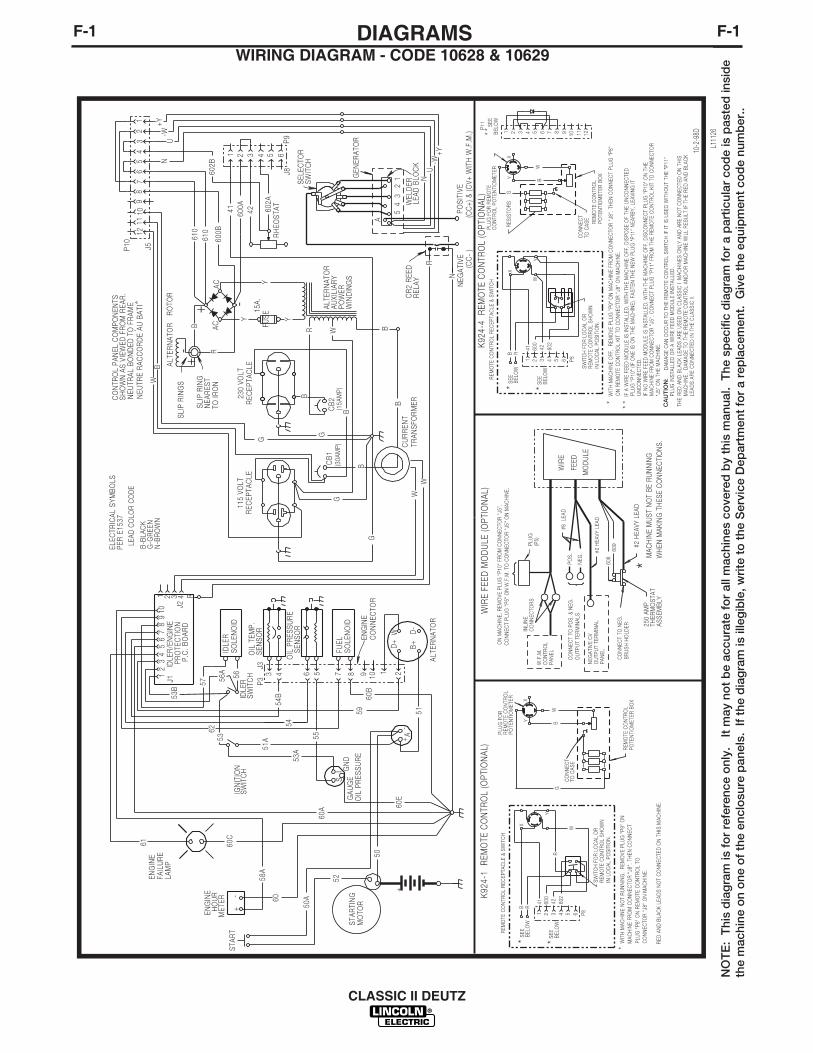
WIRING DIAGRAM - CODE 10628 & 10629DIAGRAMS

F-2
CLASSIC II DEUTZ
F-2
R
SW
ITC
H
STA
RT
STA
RTI
NG
MO
TOR
+
ENG
INE
+
52
D+
D-
B+
W
1
+A
FUEL
SO
LEN
OID
IDLE
RS
OLE
NO
ID
SEN
SO
R
7 83 4 56
ALT
ERN
ATO
R
OIL
PR
ESS
UR
EG
AU
GES
I GN
D
OIL
TEM
P.
-
HO
UR
M
ETER
-
50A
50
51
51A
60
56
55
60B
L992
0
CLA
SS
IC I
I
- W
IRIN
G D
IAG
RA
M
60E
1 2 3 4
12
34
56
78
910
IDLE
R/E
NG
INE
PR
OTE
CTI
ON
P.C
. B
OA
RD
53B
56A
57
60A
ENG
INE
FAIL
UR
ELA
MP
54B
59
58A
54
J1J2
53
53A
61 60C
IGN
ITIO
N
CO
NTR
OL
PA
NEL
CO
MP
ON
ENTS
SH
OW
N A
S V
IEW
ED F
RO
M R
EAR
.LE
AD
CO
LOR
CO
DE
B-B
LAC
KG
-GR
EEN
N-B
RO
WN
B
R
+-
+ -
Y
R W B
B
SLI
P R
ING
S
TO IR
ON
R
N
A
54
32
1
ALT
ERN
ATO
RA
UXI
LIA
RY
PO
WER
WIN
DIN
GS
CB
3C
B1
115
VOLT
REC
EPTA
CLE
230
VO
LTR
EC
EP
TAC
LE
Y
NEG
ATI
VE
SEL
ECTO
R
SW
ITC
H
WEL
DER
LEA
D B
LOC
K
AC
AC
CR
2 R
EED
REL
AY
42 602A
G
U
CB
2C
B4
FU
SE15
A.
12
34
56
78
910
1112
1 2 3 4 5 6
600A41
GEN
ERA
TOR
N-W
+Y
G
G
B
600B
610
610
602B
ALT
ERN
ATO
R
RO
TOR
SLI
P R
ING
N
EAR
EST
J5
P9
J8
PO
SIT
IVE
ELEC
TRIC
AL
SY
MB
OLS
PER
E15
37P
10
+Y
-WN
U
WB
RH
EOS
TAT
(CC
- )
(CC
+) &
(CV+
WIT
H W
.F.M
.)
Y
B
B
B
B
B
G
NEU
TRA
L B
ON
DED
TO
FR
AM
EN
EUTR
E R
AC
CO
RD
E A
U B
ATI
CU
RR
ENT
TRA
NS
FOR
MER
W W
SW
ITC
HID
LER P3
J3
OIL
PR
ESS
UR
E
SEN
SO
R
9 10EN
GIN
EC
ON
NEC
TOR
2
58
CB
1
62
Y
B
SEE BEL
OW
*W
G
PLU
G F
OR
REM
OTE
CO
NTR
OL
PO
TEN
TIO
MET
ER
B
*
P81 2 3 4 5 6
X
41 600
42 602
R
W
RB
ELO
WS
EE*
REM
OTE
CO
NTR
OL
REC
EPTA
CLE
& S
WIT
CH
XY
CO
NN
ECT
TO C
AS
E
WIT
H M
AC
HIN
E N
OT
RU
NN
ING
, R
EMO
VE P
LUG
"P
9" O
NM
AC
HIN
E FR
OM
CO
NN
ECTO
R "
J8".
TH
EN C
ON
NEC
TP
LUG
"P
8" O
N R
EMO
TE C
ON
TRO
L TO
CO
NN
ECTO
R "
J8"
ON
MA
CH
INE.
K92
4-1
RE
MO
TE C
ON
TRO
L (O
PTI
ON
AL) R
EMO
TE C
ON
TRO
LP
OTE
NTI
OM
ETER
BO
X
SW
ITC
H F
OR
LO
CA
L O
R
REM
OTE
CO
NTR
OL
SH
OW
N
IN L
OC
AL
PO
SIT
ION
.
#2 H
EA
VY
LE
AD
WIR
E F
EE
D M
OD
ULE
(OP
TIO
NA
L)
WIR
E
FEED
MO
DU
LEN
EG.
PO
S.
OU
TPU
T TE
RM
INA
LSC
ON
NEC
T TO
PO
S.
& N
EG.
CO
NN
ECT
TO N
EG.
BR
US
H H
OLD
ER
608
609
#2 H
EAVY
LEA
D
#8
LEA
D
MA
CH
INE
MU
ST
NO
T B
E R
UN
NIN
GW
HEN
MA
KIN
G T
HES
E C
ON
NEC
TIO
NS
.
*
ON
MA
CH
INE,
REM
OVE
PLU
G "
P10
" FR
OM
CO
NN
ECTO
R "
J5".
CO
NN
ECT
PLU
G "
P5"
ON
W.F
.M.
TO C
ON
NEC
TOR
"J5
" O
N M
AC
HIN
E.
250
AM
PTH
ER
MO
STA
TA
SS
EM
BLY
INLI
NE
CO
NN
ECTO
RS
W.F
.M.
CO
NTR
OL
PA
NEL
NEG
ATI
VE C
VO
UTP
UT
TER
MIN
AL
PA
NEL
PLU
G(P
5)Y
B
SEE BEL
OW
*W
G
B
*
P81 2 3 4 5 6
X
41 600
42 602
W
RB
ELO
WS
EE*
REM
OTE
CO
NTR
OL
REC
EPTA
CLE
& S
WIT
CH
XY
CO
NN
ECT
TO C
AS
E
K92
4-4
RE
MO
TE C
ON
TRO
L (O
PTI
ON
AL)
REM
OTE
CO
NTR
OL
PO
TEN
TIO
MET
ER B
OX
SW
ITC
H F
OR
LO
CA
L O
R
REM
OTE
CO
NTR
OL
SH
OW
N
IN L
OC
AL
PO
SIT
ION
.
RES
ISTO
RS
1 2 3 4 5 6 7 8 9 10 11 12
P11 S
EEB
ELO
W**
**
PLU
G F
OR
REM
OTE
CO
NTR
OL
PO
TEN
TIO
MET
ER
WIT
H M
AC
HIN
E O
FF,
REM
OVE
PLU
G "
P9"
ON
MA
CH
INE
FRO
M C
ON
NEC
TOR
"J8
". T
HEN
CO
NN
ECT
PLU
G "
P8"
ON
REM
OTE
CO
NTR
OL
KIT
TO
CO
NN
ECTO
R "
J8"
ON
MA
CH
INE.
IF A
WIR
E FE
ED M
OD
ULE
IS IN
STA
LLED
, W
ITH
TH
E M
AC
HIN
E O
FF,
DIS
PO
SE
OF
THE
UN
CO
NN
ECTE
D
PLU
G "
P10
" (IF
ON
E IS
ON
TH
E M
AC
HIN
E).
FAS
TEN
TH
E N
EW P
LUG
"P
11"
NEA
RB
Y,
LEA
VIN
G IT
UN
CO
NN
ECTE
D.
IF N
O W
IRE
FEED
MO
DU
LE IS
INS
TALL
ED,
WIT
H T
HE
MA
CH
INE
OFF
, D
ISC
ON
NEC
T P
LUG
"P
10"
ON
TH
EM
AC
HIN
E FR
OM
CO
NN
ECTO
R "
J5".
CO
NN
ECT
PLU
G "
P11
" FR
OM
TH
E R
EMO
TE C
ON
TRO
L K
IT T
O C
ON
NEC
TOR
"J5"
ON
TH
E M
AC
HIN
E.
THE
RED
AN
D B
LAC
K L
EAD
S A
RE
US
ED O
N C
LAS
SIC
I M
AC
HIN
ES O
NLY
AN
D A
RE
NO
T C
ON
NEC
TED
ON
TH
ISM
AC
HIN
E.
DA
MA
GE
TO T
HE
REM
OTE
CO
NTR
OL
AN
D/O
R M
AC
HIN
E W
ILL
RES
ULT
IF T
HE
RED
AN
D B
LAC
K
RED
AN
D B
LAC
K L
EAD
S N
OT
CO
NN
ECTE
D O
N T
HIS
MA
CH
INE.
LEA
DS
AR
E C
ON
NEC
TED
IN T
HE
CLA
SS
IC II
.
RES
ISIT
OR
S
G
CA
UT
ION
:"P
11"
PLU
G IN
STA
LLED
OR
A W
IRE
FEED
MO
DU
LE IN
STA
LLED
.
D
AM
AG
E C
AN
OC
CU
R T
O T
HE
REM
OTE
CO
NTR
OL
SW
ITC
H IF
IT IS
US
ED W
ITH
OU
T TH
E
10-9
7L
NO
TE
: T
his
dia
gra
m is
fo
r re
fere
nce
onl
y.
It m
ay n
ot
be
accu
rate
fo
r al
l mac
hine
s co
vere
d b
y th
is m
anua
l. T
he s
pec
ific
dia
gra
m f
or
a p
artic
ular
co
de
is p
aste
d in
sid
eth
e m
achi
ne o
n o
ne o
f th
e en
clo
sure
pan
els.
If
the
dia
gra
m is
ille
gib
le, w
rite
to
the
Ser
vice
Dep
artm
ent
for
a re
pla
cem
ent.
Giv
e th
e eq
uip
men
t co
de
num
ber
..
WIRING DIAGRAM - CODE 10219 & 10219CVDIAGRAMS

F-3
CLASSIC II DEUTZ
F-3
CO
NTR
OL
PA
NE
L C
OM
PO
NE
NTS
SH
OW
N A
S V
IEW
ED
FR
OM
RE
AR
.LE
AD
CO
LOR
CO
DE
B-B
LAC
KG
-GR
EE
NN
-BR
OW
N
B
R
+-
+ -
Y
R W B
B
WW
SLI
P R
ING
S
TO IR
ON
R
N
A
54
32
1
ALT
ER
NA
TOR
AU
XILI
AR
YP
OW
ER
WIN
DIN
GS
CU
RR
EN
T TR
AN
SFO
RM
ER
CB
1
115
VO
LTR
EC
EP
TAC
LE23
0 V
OLT
RE
CE
PTA
CLE
Y
NE
GA
TIV
E
SE
LEC
TOR
S
WIT
CH
WE
LDE
RLE
AD
BLO
CK
AC
AC
CR
2 R
EE
DR
ELA
Y
42 602A
G
U
CB
2
FU
SE15
A.
12
34
56
78
910
1112
1 2 3 4 5 6
600A41
GE
NE
RA
TOR
N-W
+Y
G
G
B
600B
610
610
602B
R
SW
ITC
H
STA
RT
STA
RTI
NG
MO
TOR
+
EN
GIN
E
+
52
D+
D-
B+
W21
IDLE
RS
WIT
CH
+A
FUE
LS
OLE
NO
ID
IDLE
RS
OLE
NO
ID
SE
NS
OR
7 83 4 56
ALT
ER
NA
TOR
OIL
PR
ES
SU
RE
GA
UG
ESI G
ND
ALT
ER
NA
TOR
R
OTO
R
SLI
P R
ING
N
EA
RE
ST
OIL
TE
MP
.
-
HO
UR
M
ETE
R
J5
P9
J8
PO
SIT
IVE
ELE
CTR
ICA
L S
YM
BO
LSP
ER
E15
37P
10
+Y
-WN
U
WB
-
50A
50
51
51A
60
56
55
60B
RH
EO
STA
T
(CC
- )
(CC
+) &
(CV
+ W
ITH
W.F
.M.)
(30A
MP
)(1
5AM
P)
L991
9
CLA
SS
IC I
I
- W
IRIN
G D
IAG
RA
M
60E
B
B
Y
G
NE
UTR
AL
BO
ND
ED
TO
FR
AM
EN
EU
TRE
RA
CC
OR
DE
AU
BA
TI'
1 2 3 4
12
34
56
78
910
IDLE
R/E
NG
INE
PR
OTE
CTI
ON
P.C
. B
OA
RD
53B
56A
57
60A
EN
GIN
EFA
ILU
RE
LAM
P58
54B
59
58A
54
J1J2
53
53A
61 60C
IGN
ITIO
N
109
J3P
3
EN
GIN
EC
ON
NE
CTO
R
OIL
PR
ES
SU
RE
S
EN
SO
R
CB
1
62
10-9
7L
Y
B
SEE BEL
OW
*W
G
PLU
G F
OR
REM
OTE
CO
NTR
OL
PO
TEN
TIO
MET
ER
B
*
P81 2 3 4 5 6
X
41 600
42 602
R
W
RB
ELO
WS
EE*
REM
OTE
CO
NTR
OL
REC
EPTA
CLE
& S
WIT
CH
XY
CO
NN
ECT
TO C
AS
E
WIT
H M
AC
HIN
E N
OT
RU
NN
ING
, R
EMO
VE P
LUG
"P
9" O
NM
AC
HIN
E FR
OM
CO
NN
ECTO
R "
J8".
TH
EN C
ON
NEC
TP
LUG
"P
8" O
N R
EMO
TE C
ON
TRO
L TO
CO
NN
ECTO
R "
J8"
ON
MA
CH
INE.
K92
4-1
REM
OTE
CO
NTR
OL
(OP
TIO
NA
L) REM
OTE
CO
NTR
OL
PO
TEN
TIO
MET
ER B
OX
SW
ITC
H F
OR
LO
CA
L O
R
REM
OTE
CO
NTR
OL
SH
OW
N
IN L
OC
AL
PO
SIT
ION
.
#2 H
EA
VY
LE
AD
WIR
E FE
ED M
OD
ULE
(OP
TIO
NA
L)
WIR
E
FEE
D
MO
DU
LEN
EG.
PO
S.
OU
TPU
T TE
RM
INA
LSC
ON
NEC
T TO
PO
S.
& N
EG.
CO
NN
ECT
TO N
EG.
BR
US
H H
OLD
ER
608
609
#2 H
EAVY
LEA
D
#8
LEA
D
MA
CH
INE
MU
ST
NO
T B
E R
UN
NIN
GW
HE
N M
AK
ING
TH
ES
E C
ON
NE
CTI
ON
S.
*
ON
MA
CH
INE,
REM
OVE
PLU
G "
P10
" FR
OM
CO
NN
ECTO
R "
J5".
CO
NN
ECT
PLU
G "
P5"
ON
W.F
.M.
TO C
ON
NEC
TOR
"J5
" O
N M
AC
HIN
E.
250
AM
PTH
ER
MO
STA
TA
SS
EM
BLY
INLI
NE
CO
NN
ECTO
RS
W.F
.M.
CO
NTR
OL
PA
NEL
NEG
ATI
VE C
VO
UTP
UT
TER
MIN
AL
PA
NEL
PLU
G(P
5)Y
B
SEE BEL
OW
*W
G
B
*
P81 2 3 4 5 6
X
41 600
42 602
W
RB
ELO
WS
EE*
REM
OTE
CO
NTR
OL
REC
EPTA
CLE
& S
WIT
CH
XY
CO
NN
ECT
TO C
AS
E
K92
4-4
REM
OTE
CO
NTR
OL
(OP
TIO
NA
L)
REM
OTE
CO
NTR
OL
PO
TEN
TIO
MET
ER B
OX
SW
ITC
H F
OR
LO
CA
L O
R
REM
OTE
CO
NTR
OL
SH
OW
N
IN L
OC
AL
PO
SIT
ION
.
RES
ISTO
RS
1 2 3 4 5 6 7 8 9 10 11 12
P11 S
EEB
ELO
W**
**
PLU
G F
OR
REM
OTE
CO
NTR
OL
PO
TEN
TIO
MET
ER
WIT
H M
AC
HIN
E O
FF,
REM
OVE
PLU
G "
P9"
ON
MA
CH
INE
FRO
M C
ON
NEC
TOR
"J8
". T
HEN
CO
NN
ECT
PLU
G "
P8"
ON
REM
OTE
CO
NTR
OL
KIT
TO
CO
NN
ECTO
R "
J8"
ON
MA
CH
INE.
IF A
WIR
E FE
ED M
OD
ULE
IS IN
STA
LLED
, W
ITH
TH
E M
AC
HIN
E O
FF,
DIS
PO
SE
OF
THE
UN
CO
NN
ECTE
D
PLU
G "
P10
" (IF
ON
E IS
ON
TH
E M
AC
HIN
E).
FAS
TEN
TH
E N
EW P
LUG
"P
11"
NEA
RB
Y,
LEA
VIN
G IT
UN
CO
NN
ECTE
D.
IF N
O W
IRE
FEED
MO
DU
LE IS
INS
TALL
ED,
WIT
H T
HE
MA
CH
INE
OFF
, D
ISC
ON
NEC
T P
LUG
"P
10"
ON
TH
EM
AC
HIN
E FR
OM
CO
NN
ECTO
R "
J5".
CO
NN
ECT
PLU
G "
P11
" FR
OM
TH
E R
EMO
TE C
ON
TRO
L K
IT T
O C
ON
NEC
TOR
"J5"
ON
TH
E M
AC
HIN
E.
THE
RED
AN
D B
LAC
K L
EAD
S A
RE
US
ED O
N C
LAS
SIC
I M
AC
HIN
ES O
NLY
AN
D A
RE
NO
T C
ON
NEC
TED
ON
TH
ISM
AC
HIN
E.
DA
MA
GE
TO T
HE
REM
OTE
CO
NTR
OL
AN
D/O
R M
AC
HIN
E W
ILL
RES
ULT
IF T
HE
RED
AN
D B
LAC
KLE
AD
S A
RE
CO
NN
ECTE
D IN
TH
E C
LAS
SIC
II.
RED
AN
D B
LAC
K L
EAD
S N
OT
CO
NN
ECTE
D O
N T
HIS
MA
CH
INE.
CA
UT
ION
:P
LUG
INS
TALL
ED O
R A
WIR
E FE
ED M
OD
ULE
INS
TALL
ED.
DA
MA
GE
CA
N O
CC
UR
TO
TH
E R
EMO
TE C
ON
TRO
L S
WIT
CH
IF IT
IS U
SED
WIT
HO
UT
THE
"P11
"
NO
TE
: T
his
dia
gra
m is
fo
r re
fere
nce
onl
y.
It m
ay n
ot
be
accu
rate
fo
r al
l mac
hine
s co
vere
d b
y th
is m
anua
l. T
he s
pec
ific
dia
gra
m f
or
a p
artic
ular
co
de
is p
aste
d in
sid
eth
e m
achi
ne o
n o
ne o
f th
e en
clo
sure
pan
els.
If
the
dia
gra
m is
ille
gib
le, w
rite
to
the
Ser
vice
Dep
artm
ent
for
a re
pla
cem
ent.
Giv
e th
e eq
uip
men
t co
de
num
ber
..
WIRING DIAGRAM - CODE 10220 & 10220CVDIAGRAMS

F-4DIAGRAMSF-4
CLASSIC II DEUTZ
C
L11
863
CLA
SS
IC II
-
WIR
ING
DIA
GR
AM
LEA
D C
OLO
R C
OD
E
B-B
LAC
KG
-GR
EE
NN
-BR
OW
N
R-R
ED
U-B
LUE
W-W
HIT
EY
-YE
LLO
W
ELE
CTR
ICAL
SYM
BO
LSP
ER
E15
37C
ON
TRO
L P
AN
EL
CO
MP
ON
EN
TSS
HO
WN
AS
VIE
WE
D F
RO
M R
EA
R.
NE
UTR
AL
BO
ND
ED
TO
FR
AME
NE
UTR
E R
AC
CO
RD
E A
U B
ATI
’
700B
700A
+-
+ -
Y
R40
0D
B
10
WW
SLI
P R
ING
S
TO IR
ON
346
347
A
54
32
1
ALT
ER
NA
TOR
AU
XIL
IAR
YP
OW
ER
WIN
DIN
GS
CU
RR
ENT
TRA
NSF
OR
MER
CB
2
115
VO
LTR
ECE
PTA
CLE
230
VO
LTR
EC
EP
TAC
LE
Y
NEG
ATI
VE
SE
LEC
TOR
SW
ITC
H
WE
LDE
RLE
AD
BLO
CK
AC
AC
CR
2 R
EED
RE
LAY
42 602A
GN
D-E
U
CB
3
F
US
E15
A.
12
34
56
78
910
1112
1 2 3 4 5 6
600A41
GE
NER
ATO
R
N-W
+Y
48
GN
D-D
10
600B
610
610
602B
R
SW
ITC
HS
TAR
T
STA
RTI
NG
MO
TOR
+
EN
GIN
E
+
52
D+
D-
B+
W21
IDLE
RS
WIT
CH
+ A
FUE
LS
OLE
NO
ID
IDLE
RS
OLE
NO
ID
SE
NSO
R
7 83 4 56
ALT
ER
NA
TOR
AM
ME
TER
GA
UG
ESI G
ND
RE
CE
PTA
CLE
RO
TOR
SLI
P R
ING
NE
AR
ES
T
OIL
TE
MP
.
-
HO
UR
ME
TER
J5
P8
J8
PO
SIT
IVE
P10
+Y-W
NU
400D
400E
-
50A
50
51
51A
60
56
55
60B
RH
EOS
TAT
(CC
- )(C
C+)
& (C
V+ W
ITH
W.F
.M.)
60E
300B
650
GN
D-F
1 2 3 4
12
34
56
78
910
IDLE
R/E
NG
INE
PR
OTE
CTI
ON
P.C
. BO
ARD
53B 56
A57
60A
EN
GIN
EFA
ILU
RE
LAM
P
54B
59
58A
54
J1
J2
53
53A
61 60C
IGN
ITIO
N
109
J3P
3
EN
GIN
EC
ON
NE
CTO
R
OIL
PR
ES
SU
RE
S
EN
SO
R
62
W
G
B
XY
CO
NN
ECT
TO C
AS
E
K92
4-5
RE
MO
TE C
ON
TRO
L (O
PTI
ON
AL)
REM
OTE
CO
NTR
OL
PO
TEN
TIO
MET
ER
BO
X
RE
SIS
TOR
S
PLU
G F
OR
REM
OTE
CO
NTR
OL
PO
TEN
TIO
MET
ER
A
A
AA
15A
CB
4300A
400E
400A
CB
120
A20
A15
A
#2 H
EA
VY
LE
AD
WIR
E F
EE
D M
OD
ULE
(OP
TIO
NA
L)
WIR
E
FEE
D
MO
DU
LE
}
NEG
.P
OS
.O
UTP
UT
TER
MIN
ALS
CO
NN
EC
T TO
PO
S. &
NEG
. {C
ON
NE
CT
TO N
EG
.B
RU
SH H
OLD
ER
608
609
#2 H
EA
VY
LE
AD
#8 L
EA
D
MAC
HIN
E M
US
T N
OT
BE
RU
NN
ING
WH
EN M
AK
ING
TH
ES
E C
ON
NE
CTI
ON
S.
*
ON
MAC
HIN
E, R
EMO
VE
PLU
G "P
10" F
RO
M C
ON
NEC
TOR
"J5"
.C
ON
NE
CT
PLU
G "P
5" O
N W
.F.M
. TO
CO
NN
ECTO
R "J
5" O
N M
ACH
INE
.
250
AM
PTH
ER
MO
STA
TA
SS
EM
BLY
INLI
NE
CO
NN
EC
TOR
SW
.F.M
.C
ON
TRO
LP
AN
EL
NEG
ATI
VE
CV
OU
TPU
T TE
RM
INA
LP
AN
EL
PLU
G(P
5)
AY
600
4260
2
W
48
41W
R
400B
W
GR
EM
OTE
CO
NTR
OL
REM
OTE
CO
NTR
OL
SWIT
CH
SHO
WN
IN L
OC
AL P
OSI
TION
OIL
PR
ES
SUR
E
350
400C
NO
TE
: T
his
dia
gra
m is
fo
r re
fere
nce
onl
y.
It m
ay n
ot
be
accu
rate
fo
r al
l mac
hine
s co
vere
d b
y th
is m
anua
l. T
he s
pec
ific
dia
gra
m f
or
a p
artic
ular
co
de
is p
aste
d in
sid
eth
e m
achi
ne o
n o
ne o
f th
e en
clo
sure
pan
els.
If
the
dia
gra
m is
ille
gib
le, w
rite
to
the
Ser
vice
Dep
artm
ent
for
a re
pla
cem
ent.
Giv
e th
e eq
uip
men
t co
de
num
ber
..
WIRING DIAGRAM - CODE 10910

F-5
CLASSIC II DEUTZ
F-5
PAR
T N
O.
WEL
DER
AB
CD
EF
GH
AC
ON
TRO
L PA
NEL
F
G
B
H
D
EC
O HO
LE
O MO
UN
TIN
GH
OLE
N.A
.
N.B
.
NO
TES: O
IL A
ND
WAT
ER IN
EN
GIN
E,B
UT
NO
FU
EL.
N.A
. C
ENTE
R O
F G
RAV
ITY
WIT
H
O
S107
66-6
J
J
K
KL
DIM
EN
SIO
N P
RIN
T
S
1076
6
MET
RIC
cm
(EN
GLI
SH in
.)
150.
7(5
9.32
)4.
8(1
.90)
58.4
(23.
00)
79.2
(31.
19)
43.8
(17.
25)
105.
8(4
1.66
)19
.1(7
.51)
CLA
SSIC
II
106.
7(4
2.0)
16.5
(6.5
0)
N.B
.
1.5
4 (.5
6) T
RAI
LER
M
OU
NTI
NG
HO
LES.
94.3
(37.
12)
61.0
(24.
00)
104.
0(4
0.94
)
47.0
(18.
50)
52.4
(20.
62)
10.2
(4.0
0)10
.2(4
.00)
1.54
(.56
) SK
ID1.
54 (.
56)
SKID
MO
UN
TIN
G
.N.C
.. D
IME
NS
ION
TO
TO
P O
FE
XHAU
ST E
LBO
W O
RR
AIN
CAP
.
L
N.C
.
02/
26
/ 03
DIAGRAMS

NOTES
CLASSIC II DEUTZ

WARNING
AVISO DEPRECAUCION
ATTENTION
WARNUNG
ATENÇÃO
Spanish
French
German
Portuguese
Japanese
Chinese
Korean
Arabi
READ AND UNDERSTAND THE MANUFACTURER’S INSTRUCTION FOR THIS EQUIPMENT AND THE CONSUMABLES TO BEUSED AND FOLLOW YOUR EMPLOYER’S SAFETY PRACTICES.
SE RECOMIENDA LEER Y ENTENDER LAS INSTRUCCIONES DEL FABRICANTE PARA EL USO DE ESTE EQUIPO Y LOSCONSUMIBLES QUE VA A UTILIZAR, SIGA LAS MEDIDAS DE SEGURIDAD DE SU SUPERVISOR.
LISEZ ET COMPRENEZ LES INSTRUCTIONS DU FABRICANT EN CE QUI REGARDE CET EQUIPMENT ET LES PRODUITS AETRE EMPLOYES ET SUIVEZ LES PROCEDURES DE SECURITE DE VOTRE EMPLOYEUR.
LESEN SIE UND BEFOLGEN SIE DIE BETRIEBSANLEITUNG DER ANLAGE UND DEN ELEKTRODENEINSATZ DES HER-STELLERS. DIE UNFALLVERHÜTUNGSVORSCHRIFTEN DES ARBEITGEBERS SIND EBENFALLS ZU BEACHTEN.
● Do not touch electrically live parts orelectrode with skin or wet clothing.
● Insulate yourself from work andground.
● No toque las partes o los electrodosbajo carga con la piel o ropa moja-da.
● Aislese del trabajo y de la tierra.
● Ne laissez ni la peau ni des vête-ments mouillés entrer en contactavec des pièces sous tension.
● Isolez-vous du travail et de la terre.
● Berühren Sie keine stromführendenTeile oder Elektroden mit IhremKörper oder feuchter Kleidung!
● Isolieren Sie sich von denElektroden und dem Erdboden!
● Não toque partes elétricas e elec-trodos com a pele ou roupa molha-da.
● Isole-se da peça e terra.
● Keep flammable materials away.
● Mantenga el material combustiblefuera del área de trabajo.
● Gardez à l’écart de tout matérielinflammable.
● Entfernen Sie brennbarres Material!
● Mantenha inflamáveis bem guarda-dos.
● Wear eye, ear and body protection.
● Protéjase los ojos, los oídos y elcuerpo.
● Protégez vos yeux, vos oreilles etvotre corps.
● Tragen Sie Augen-, Ohren- und Kör-perschutz!
● Use proteção para a vista, ouvido ecorpo.

WARNING
AVISO DEPRECAUCION
ATTENTION
WARNUNG
ATENÇÃO
Spanish
French
German
Portuguese
Japanese
Chinese
Korean
Arabic
LEIA E COMPREENDA AS INSTRUÇÕES DO FABRICANTE PARA ESTE EQUIPAMENTO E AS PARTES DE USO, E SIGA ASPRÁTICAS DE SEGURANÇA DO EMPREGADOR.
● Keep your head out of fumes.● Use ventilation or exhaust to
remove fumes from breathing zone.
● Los humos fuera de la zona de res-piración.
● Mantenga la cabeza fuera de loshumos. Utilice ventilación oaspiración para gases.
● Gardez la tête à l’écart des fumées.● Utilisez un ventilateur ou un aspira-
teur pour ôter les fumées des zonesde travail.
● Vermeiden Sie das Einatmen vonSchweibrauch!
● Sorgen Sie für gute Be- undEntlüftung des Arbeitsplatzes!
● Mantenha seu rosto da fumaça.● Use ventilação e exhaustão para
remover fumo da zona respiratória.
● Turn power off before servicing.
● Desconectar el cable de ali-mentación de poder de la máquinaantes de iniciar cualquier servicio.
● Débranchez le courant avant l’entre-tien.
● Strom vor Wartungsarbeitenabschalten! (Netzstrom völlig öff-nen; Maschine anhalten!)
● Não opere com as tampas removidas.● Desligue a corrente antes de fazer
serviço.● Não toque as partes elétricas nuas.
● Do not operate with panel open orguards off.
● No operar con panel abierto oguardas quitadas.
● N’opérez pas avec les panneauxouverts ou avec les dispositifs deprotection enlevés.
● Anlage nie ohne Schutzgehäuseoder Innenschutzverkleidung inBetrieb setzen!
● Mantenha-se afastado das partesmoventes.
● Não opere com os paineis abertosou guardas removidas.

• Sales and Service through Subsidiaries and Distributors Worldwide •
Cleveland, Ohio 44117-1199 U.S.A. TEL: 216.481.8100 FAX: 216.486.1751 WEB SITE: www.lincolnelectric.com
• World's Leader in Welding and Cutting Products •


