Embed Size (px)
Citation preview

Operator’s Handbook
ILM200Family of Cryogen Level Meters
Issue 1.5
April 2000
File reference: ILM-15.DOC
Oxford Instruments
Superconductivity
Tubney Woods, Abingdon,
Oxon, OX13 5QX, England
Tel: +44 (0)1865 393 200
Fax: +44 (0)1865 393 333
E-mail:[email protected]
www.oxford-instruments.com
Contents
1 Introduction .............................................................................................................. 5
1.1 Use of this Manual...................................................................................... 5
1.2 Description of the ILM200 Family .............................................................. 5
1.3 Principles of Operation .............................................................................. 5
1.3.1 Helium Level Probe................................................................... 5
1.3.2 Nitrogen Level Probe................................................................ 6
1.3.3 Why Two Different Sensing Methods Are Used ..................... 6
2 Safety......................................................................................................................... 7
2.1 Protective Ground ...................................................................................... 7
2.2 Working Environment................................................................................ 7
2.3 Repair and Adjustment .............................................................................. 7
3 Installation ................................................................................................................ 8
3.1 Supply Connections .................................................................................... 8
3.2 Probe Connections...................................................................................... 8
3.3 Compatibility with Earlier Probes.............................................................. 8
3.4 Auxiliary Port Connections......................................................................... 9
3.5 Relay Contact............................................................................................ 10
3.6 Connections for Automatic Magnet Run Down ..................................... 10
3.7 Analogue Outputs .................................................................................... 11
3.8 RS232 Serial Data Line Connections ........................................................ 11
3.9 The Oxford Instruments Isobus................................................................ 12
3.10 GPIB (IEEE-488) Connection (Optional) ................................................... 12
3.11 The GPIB to ISOBUS Gateway .................................................................. 13
4 Operation ................................................................................................................ 14
4.1 Front Panel Controls................................................................................. 14
4.2 First Time Operation................................................................................. 15
4.3 "Err" Display ............................................................................................. 16
4.4 Sample Rate Selection.............................................................................. 16
4.5 Calibration ................................................................................................ 16
4.5.1 Trimming the Calibration....................................................... 16
4.5.2 Setting the Default Calibration ............................................. 17
4.6 Storing Calibration and other Power-Up Defaults ................................. 18
5 Auto-Fill and Alarms............................................................................................... 19
5.1 Level Thresholds ....................................................................................... 19
5.2 Automatic Filling ...................................................................................... 19
5.3 Automatic Rate Switching ....................................................................... 20
5.4 Audible Alarm........................................................................................... 21
5.5 Automatic Shut Down.............................................................................. 21
6 Remote Operation .................................................................................................. 22
6.1 Introduction.............................................................................................. 22
6.2 Communication Protocols ........................................................................ 22
6.3 Commands and Responses ....................................................................... 22
6.4 Numeric Parameters ................................................................................. 23

6.5 Use with Oxford Instruments ISOBUS...................................................... 23
6.6 The GPIB Interface .................................................................................... 24
6.6.1 Sending Commands via the GPIB........................................... 25
6.6.2 Accepting Responses via the GPIB ......................................... 25
6.6.3 The Status Byte, Use of a Serial Poll ...................................... 25
6.6.4 Use of the Service Request Line ............................................. 26
6.6.5 Use of the Device Clear Function........................................... 26
6.6.6 Use of the Interface Clear (IFC) Function .............................. 26
6.6.7 Non-Implemented Features of the GPIB ............................... 26
6.6.8 Compatibility with IEEE-488.2................................................ 27
6.6.9 Use of the GPIB Interface as a GATEWAY to ISOBUS ........... 27
6.6.10 Writing a "Rugged" GPIB Control Program.......................... 27
7 Command List ......................................................................................................... 28
8 Command Syntax .................................................................................................... 29
8.1 User Commands........................................................................................ 29
8.2 Interpreting the Status Message ............................................................. 31
8.2.1 Example Sequence.................................................................. 33
9 Configuration and Test Mode................................................................................ 35
9.1 Use of Test Mode...................................................................................... 35
9.2 Entering Test Mode.................................................................................. 35
9.3 Test t.01 Testing the Display and Relays ................................................. 35
9.4 Test t.02 Testing the Keys ....................................................................... 35
9.5 Test t.03 Setting the GPIB Address ......................................................... 36
9.6 Test t.04 The Diagnostic Front Panel Display......................................... 36
9.7 Test t.05 Configuring the Channels........................................................ 36
9.8 Test t.06 Calibrating the Current Sources .............................................. 37
9.9 Test t.07 Setting Probe Active Length.................................................... 38
9.10 Test t.08 Setting Helium Probe Currents................................................ 38
9.11 Test t.09 Setting Helium Probe Pulse Widths......................................... 39
9.12 Test t.10 Setting Helium Probe Sample Rates........................................ 39
9.13 Test t.11 Setting Full, Fill and Low Thresholds....................................... 39
9.14 Test t.12 Setting Stepper Motor Operating Mode ................................ 40
9.15 Test t.13 Manual Adjustment of Needle Valve...................................... 40
9.16 Test t.14 Setting Helium Probe Wire Resistivity..................................... 40
9.17 A Final Reminder ...................................................................................... 40
10 Servicing .................................................................................................................. 41
10.1 Safety ........................................................................................................ 41
10.2 Circuit Description .................................................................................... 41
10.3 Reset Procedures....................................................................................... 42
10.3.1 Entry to Test Mode ................................................................. 42
10.3.2 Two Button Reset ................................................................... 43
10.3.3 Three Button Reset................................................................. 43
11 In Case of Difficulty ................................................................................................ 44
12 Specification............................................................................................................ 45
13 Quick Reference Guide........................................................................................... 47
13.1 Panel Controls and Lamps........................................................................ 47
13.2 Serial / GPIB Commands ........................................................................... 47
13.3 Interpreting the Status Message ............................................................. 48
13.4 Test Mode Menu....................................................................................... 49
14 Circuit Diagrams...................................................................................................... 52
WarningsBefore you operate this equipment for the first time, please make sure that you are
aware of the precautions which you must take to ensure your own safety. In particular
please read the Safety section of this manual.
Explosive AtmospheresThe ILM is intended quite specifically for use with liquid helium and liquid nitrogen. It is
not intended for use in an inflammable or explosive atmosphere. It must not be used
under any circumstances for monitoring the level of combustible liquids or in the
presence of combustible or explosive gases.
Important NoteThis manual is part of the product that you have bought. Please keep it for the whole
life of the product and make sure that you incorporate any amendments which might be
sent to you. If you sell or give away the product to someone else please give them the
manual too. Before you attempt to install or operate this equipment for the first time,
please make sure that you are aware of the precautions that you must take to ensure
your own safety.
Oxford Instruments Superconductivity Limited, April 2000. All rights strictly reserved.
5
1 Introduction
1.1 Use of this ManualThis manual provides operating and service information for the Oxford Instruments
ILM200 Family of Cryogen Level Meters. Sections 1-4 provide essential information and
should be read before operating the instrument for the first time.
The remainder of the manual provides more detail on specific aspects and may be
referred to as required. Section 11 attempts to identify some of the more common
operating pitfalls and may be useful if problems are encountered.
A Quick Reference guide is provided in Section 13 to help to remind you of the
commands and configuration parameters. Please feel free to copy this and keep a copy
beside the instrument if you wish.
1.2 Description of the ILM200 FamilyILM200 is a family of Intelligent Cryogen Level Meters with general application in systems
containing liquid helium or liquid nitrogen. The family comprises five instruments. The
last two digits of the type number specify the number of helium and nitrogen channels
respectively. Thus ILM221 is a three channel instrument with two helium channels and
one nitrogen channel. From now on, we shall use “ILM” to represent any member of the
family.
ILM uses a superconductive wire probe to measure the depth of liquid helium and a
capacitance probe to measure the depth of liquid nitrogen. ILM can have up to three
measurement channels, with dedicated displays used for each channel.
ILM is microprocessor based and incorporates all the logic needed to control an
automatic filling operation or to de-energise a magnet safely should the cryogen level
fall below a safe value. All members of the family include an RS232 Serial Computer
Interface as standard and if required may be fitted with an optional GPIB (IEEE-488)
Interface.
Manual operation of the ILM is by means of front panel push buttons and associated
status lamps.
1.3 Principles of Operation1.3.1 Helium Level ProbeThe probe consists of a length of superconductive wire extending from the bottom to the
top of the helium reservoir. Normally the probe will be mounted vertically, though other
geometries are possible to suit individual shapes of reservoir.
6
The probe relies on the wire below the liquid surface being more efficiently cooled than
that in the gas above the liquid. Thus the Joule heating of the resistive section of the
wire is sufficient to keep this above its critical temperature where it is in gas but not
where it is in liquid. To maintain this situation requires the correct value of current in the
wire. The graph accompanying the probe drawing at the end of this manual shows how
this current varies as a function of the temperature of the liquid in the reservoir. With no
current in the wire, the entire length will become superconducting. It is therefore
necessary to include a small heater resistor in thermal contact with the top of the wire to
drive the top end of the wire into its resistive state. Provided the current in the wire is
sufficient this resistive region will then propagate down the wire to the liquid surface.
When current has been flowing for sufficient time to ensure that the resistive region has
reached the liquid, the voltage across the wire is measured and will be directly
proportional to the length of wire in gas, from which the liquid level may be calculated.
When the measurement has been made, the current through the wire is turned off and
the measured reading displayed. The process is repeated at intervals varying from a few
seconds to a few hours, depending upon the expected rate of change in the level.
The maximum probe length that can be measured, depends upon the resistivity of the
probe wire. Prior to firmware version 1.08, ILM was designed to handle the standard
Oxford Instruments probe wire, with a typical resistivity of 178 ohms/metre. Since version
1.08 this parameter may be adjusted up to a maximum value of 200 ohms/metre. There
are now two types of wire in use:. For probes up to 1.4m active length, the standard wire
is nominally 166 ohms/metre and operates at a current of 130mA. For probes up to 2m
active length, a thicker wire is used, with a nominal resistivity of 61.2 ohms/metre,
operating at a current of 250mA.
1.3.2 Nitrogen Level ProbeThe nitrogen probe is constructed of two concentric stainless steel tubes. The annular
space between these acts as a capacitor with the dielectric consisting of liquid or gaseous
nitrogen. Liquid nitrogen has a relative permittivity of 1.45, so that the capacitance
increases by around 45% for the portion of the probe that is in liquid. The probe head
incorporates an oscillator, which uses the probe capacitance to define its period. Hence
the oscillation frequency may be used as an indicator of liquid level. There are no
adjustments in the probe head for ILM. The working range of the oscillator (5 kHz to 65
kHz) can handle the full range of probe lengths up to 2 metres.
1.3.3 Why Two Different Sensing Methods Are UsedThe capacitance method cannot be used routinely for liquid helium. (It can be used for
certain specialised applications where the reservoir is strictly isothermal.) The relative
permittivity of liquid helium is only 1.055, which is close to the figure for cold helium gas
at 4.2K. Thus the probe would be more responsive to temperature gradients within the
gas above the liquid surface, than to the position of the surface.
With modern high-Tc superconductors, it is possible to make a superconductive nitrogen
probe. However this would be much less robust than the capacitive probe, which works
well for nitrogen. Hence ILM uses the most appropriate sensing technique for each
cryogen. By allowing ILM to accept inputs from either type of probe, there is no cost
penalty in using two different sensing methods.

7
2 SafetyThe following general safety precautions must be observed during the operation, service
and repair of this instrument.
2.1 Protective GroundTo minimise shock hazard the instrument must be connected to an electrical ground. The
ground wire (green/yellow) in the instrument power cable must be connected to the
installation electrical ground system. Do not use extension cords without a protective
earth conductor. Do not disconnect the protective ground inside or outside the
instrument. Do not have external circuits connected to the instrument when its
protective ground is disconnected.
2.2 Working EnvironmentThe ILM indicator unit is not designed to be water or splash proof. Therefore it should
not be exposed to rain or excessive moisture.
Neither the indicator unit nor the probes are designed to be used in areas where there
are flammable or explosive gases or fumes.
2.3 Repair and AdjustmentSome internal adjustments can be made to ILM. Although we do not encourage you to
make these adjustments we try to supply you with enough information to allow you to
do it safely. Disconnect the AC power supply before you remove the covers or fuses,
because dangerous voltages are accessible on the circuit board and other components. It
is not sufficient to switch off the main power switch. Capacitors inside the instrument
and the power connector filter, may remain charged after removal of AC power.
Discharge these carefully before you start work.
Some fault finding operations can only be carried out with power connected to the
instrument. If you have to reconnect the AC power supply with the protective covers
removed you must remember that you are putting your life at risk. You should only do
this type of work if you are suitably qualified and sufficiently skilled to understand all the
risks you are taking.
8
3 Installation
3.1 Supply ConnectionsBefore applying power to the instrument, ensure that the voltage selector on the rear
panel is correctly set for the intended supply voltage.
If necessary, open the voltage selector panel using the slot provided, withdraw the
voltage selector and replace it in the correct orientation for the intended voltage. Check
that the correct fuses are fitted, then close the voltage selector panel.
Fuse ratings are:
100-120v1.6A Type T (Slow Blow)
200-240v0.8A Type T (Slow Blow)
3.2 Probe ConnectionsProbes are connected by means of 9-way D-sockets on the rear panel. Up to 3 of these
may be fitted, depending upon the instrument type. Their position corresponds logically
to the associated display on the front panel. Probes 1 and 2 may be used for either
Helium or Nitrogen. Probe 3 may only be used for Nitrogen. Pin outs used are the same
for either probe and no damage will be caused if the wrong type of probe is plugged in
by mistake.
Pin Connections are:
Pin Name Helium Probe Nitrogen Probe
1 VHIGH V (Top) n/c
2 VLOW V (Bottom) n/c
3 (Unused)
4 FREQ IN Link to 5 OUTPUT FREQ
5 FREQ OUT Link to 4 n/c
6 IHIGH I (Top) n/c
7 ILOW I (Bottom) 0 V
8 +12 V n/c +12 V
9 CHASSIS GND SCREEN SCREEN
3.3 Compatibility with Earlier ProbesThe design of the Helium Probe for the ILM family is unchanged from that for earlier
instruments, except for the type of connectors used. Old style probes may be used with
the new meter, provided a suitable interconnecting lead is used.
The design of the Nitrogen Probe, though based on the same principle, has changed in
detail. Old style probes are not compatible with ILM and should not be connected to it.
9
Users familiar with Oxford Instruments earlier Helium Level meters models HLM2 and
4016 should note that the direction of current flow through the helium level probe is
reversed with respect to these instruments. The top of the probe is now positive, where
it was previously negative. This has no effect on the operation of the probe. However
any users who may have built a dummy "test probe" incorporating an LED to monitor
current flow, will need to reverse the connections to the LED. As with earlier
instruments, it is important not to swap Voltage (V) and Current (I) leads, since the probe
incorporates a small start-up resistor in the top current lead ITOP and will not work reliably
if this is transposed with the VTOP lead.
3.4 Auxiliary Port ConnectionsAn auxiliary port is provided in the form of a 15 way D socket on the rear panel. Four
digital outputs are available at this port, which may be used to drive relays to control
autofilling and external alarms. The outputs are open-collector transistors (Specification
as for ULN2803A) and can sink up to 500mA from a supply of up to 12V maximum. When
driving an inductive load, it is recommended that a diode is connected across the load to
absorb the stored energy. When the optional internal relays are fitted (see below), these
are connected to the auxiliary port outputs and provide an effective pull-up resistance to
the +11 volt line. The internal alarm sounder is similarly connected to the Relay 4 output.
For low power loads, current may be drawn from pin 15, which is connected via a diode
and fuse to the internal unregulated 11 volt line. A maximum of 500mA total may be
drawn from this source.
Four further digital output lines are available to drive a small stepper motor. These may
be used to control the filling of a small vessel by means of a motorised needle valve.
In addition to the digital outputs there are four digital inputs available. Three of these
may be taken high, to inhibit autofilling on the three channels (for example in the event
of an empty storage dewar). The fourth input K7, may be taken high to initiate an
Autofill, if one is possible. In the normal course of events, filling will start automatically
when the level falls below a FILL level, and will continue until it reaches the FULL level.
There may be occasions when it is desirable to start an autofill, before the level has fallen
all the way to the FILL threshold. If K7 is taken high filling will start on any channels
configured for autofilling, provided the level is below the FULL threshold, and will then
continue normally.
10
Pin connections at the auxiliary socket are:
Pin Signal Name Function
1 Output Bit 0 Stepper Motor
9 Output Bit 1 Stepper Motor
2 Output Bit 2 Stepper Motor
10 Output Bit 3 Stepper Motor
3 Output Bit 4 Fill Relay 1
11 Output Bit 5Fill Relay 2
4 Output Bit 6 Fill Relay 3
12 Output Bit 7 Alarm Relay 4
5 Input K4 Inhibit Autofill 1
13 Input K5 Inhibit Autofill 2
6 Input K6 Inhibit Autofill 3
14 Input K7 Initiate Autofill
7 +5 volt rail
15 Driver Protection / +11 volt rail
8 0 volt rail
3.5 Relay ContactConnections Internal relays are available on ILM as an option. These have contacts rated
to carry up to 5 amps at up to 250 volts AC. They are intended for driving solenoid valves
or mains rated contactors directly. To ensure safety when using these relays, connections
to these relays are made via terminal blocks within the instrument. ILM should be
unplugged from its mains supply before removing the top cover to make connection to
the relay contacts. The incoming wires should be brought in via the cable gland on the
rear panel. After the connections have been made the cover should be replaced before
connecting ILM to the mains supply.
The connections are labelled TB1 to TB4 (corresponding to relays 1 to 4). Three terminals
are available for each relay. The terminal nearest the front of the instrument is the
Common contact. The middle terminal is the Normally Open contact and the terminal
nearest the rear panel is the Normally Closed contact. With the instrument switched off,
or the relay not active, Common is linked to Normally Closed. When the relay is active,
Common is linked to Normally Open.
3.6 Connections for Automatic Magnet Run DownOne common application of the relay contacts is to run down a magnet in the event that
the Helium level falls below the LOW threshold. Run down is initiated by providing a
contact closure to the magnet power supply. The contacts to be linked are pins 7 and 14
of the PARALLEL I/O socket on the IPS family of Oxford Instruments Power Supplies. (On
the earlier PS120-10 and PS120-3 power supplies, the same pin connections are used but
the socket is labelled AUXILIARY I/O on the rear panel.)
11
A pair of wires should be run from these pins to the COMMON and NORMALLY open
contacts (i.e. the front and middle terminals) of the relay to be used. Normally this will be
the relay associated with the channel being used for Helium level measurement.
However if a helium autofill system is also in use, another relay may be used for
rundown. Refer to section 9.6, for details on configuring the relays for different
purposes.
3.7 Analogue OutputsWhere none of the channels in an ILM have been configured to use the stepper motor
output lines for controlling autofilling, three of these four lines (bits 0 to 2) are
reallocated to provide pseudo analogue output signals representing the levels on the
three channels. These outputs are intended only to drive a chart recorder or similar for
trend recording. For precision data logging the computer interface should always be
used. The pseudo analogue signal is achieved by alternately pulling the output pin to 0v
and releasing it, with a time dependent waveform, the mean value of which represents
the analogue output. To use the output, a pull up resistor is required to a positive
voltage (not greater than 25V), followed by a passive filter with a time constant of
around 5 seconds. A typical output lead giving analogue outputs in the range 0 to 1V is
shown in circuit CNC6802 at the end of this manual. Note that no analogue outputs
are available if any channel is configured to use a stepper motor for autofill.
3.8 RS232 Serial Data Line ConnectionsThe bi-directional serial data link from the computer is connected via a 25 way D-socket
on the rear panel. ILM is configured as a DCE with the standard pin outs given below.
The majority of computer RS232 interfaces are configured as a DTE and are fitted with a
25 way D plug. For this type of connector, a simple lead connecting pin 1 to pin 1, pin 2
to pin 2 etc. is all that is required. For computers fitted with a 9 way D plug for RS232,
(AT style COM port), a standard "AT lead" fitted with a 9 way socket and a 25 way plug is
required.
Pin connections at the ILM RS232 socket are:
Pin Signal Name Notes
1 FG Linked to Chassis Ground in ILM
2 TD Data from Computer to ILM
3 RD Data from ILM to Computer
4 RTS Linked to Pin 5 in ILM
5 CTS Linked to Pin 4 in ILM
6 DSR Linked to +5V when ILM is powered
7 SG Linked to Digital Ground in ILM
8 DCD Linked to +5V when ILM is powered
All other pins are open circuit.
ILM does not require signals to be present on any of the "modem control" lines, RTS or
DTR (pin 20). RTS is looped back as CTS and logic high levels are returned on DSR and
DCD to ensure maximum compatibility with any requirement of the computer.
12
Voltage levels for the transmitted and received data are:
Tx Data High > +5.5V
Tx Data Low < -5.5V
Rx Data High Threshold < +2.6V
Rx Data Low Threshold > +1.4V
Max Rx Input Voltage +/-30V
Data protocols are:
Baud Rate 9600
Tx Start Bits 1
Tx Data Bits 8
Tx Stop Bits 2
Rx Start Bits 1
Rx Data Bits 8
Rx Stop Bits 1 or 2
Parity None
3.9 The Oxford Instruments IsobusA unique feature of ILM and other Oxford Instruments products, is the ability to connect
a number of instruments simultaneously, to a single RS232 port on a computer and to
control each one independently. This is done by means of an ISOBUS cable which carries
a single MASTER connector (25-way D socket) and up to eight, daisy-chained SLAVE
connectors (25-way D plugs). Each slave connector incorporates full optical isolation so
that the slaves are all isolated from the master and from each other. The slave
connectors draw their power from the individual instruments, via the DCD signal on pin
8. The master connector may draw its power from either DTR or RTS signals from the
computer.
To use ISOBUS, a special communication protocol is required, which is part of the
command structure of Oxford Instruments products and is described in section 6.5.
3.10 GPIB (IEEE-488) Connection (Optional)If the optional GPIB interface is fitted, connections to the GPIB are made via a standard
24 way GPIB connector. Assignment of the connector pins conforms to the standard IEEE-
488.1. Connections should be made using a standard GPIB cable. GPIB connections
should never be made or broken whilst the monitor or any of the instruments
connected to the Bus are powered up. Failure to observe this precaution can result in
damage to one or more instruments.
The GPIB interface complies fully with IEEE-488.1-1987 as a talker/listener, able to
generate service requests and respond to serial poll and device clear commands. It does
not support parallel polling and has no trigger function. Open collector drivers are used
on the bus lines so it does not prevent parallel polling of other devices on the bus. Its
complete GPIB capability is specified by the Capability Identification Codes:-
SH1 AH1 T6 L4 SR1 RL0 PP0 DC1 DT0 C0 E1
13
Two lamps are fitted to the rear panel immediately below the GPIB connector, to assist in
diagnosing any GPIB communication problems. The RED lamp lights whenever the ILM is
addressed to TALK and the GREEN lamp lights whenever it is addressed to LISTEN. The
behaviour of the lamps is very dependent on the GPIB monitor in use. Some controllers
un-address an instrument at the end of any transaction, in which case the lamps will just
blink on for each transaction. Others leave instruments addressed between transactions
in which case one or other lamp may remain lit depending on whether ILM was last
addressed to talk or to listen.
Before any communication can occur, ILM must be given a unique GPIB address. By
default, ILM is supplied with its address set to 24. If this address is already in use by
another instrument on the bus, it can be changed from the front panel via the Test
Mode. This is described in section 9.5.
3.11 The GPIB to ISOBUS GatewayAn ILM fitted with a GPIB interface has the ability to act as a GATEWAY to an ISOBUS
cable, allowing other instruments to be linked to the GPIB without themselves requiring
GPIB interfaces. This can enable other Oxford Instruments products, for which an internal
GPIB interface is not available, to be linked. It offers the additional advantage of optical
isolation between these instruments and the GPIB.
To use the gateway, all that is required is GATEWAY MASTER ADAPTOR. This allows the
25 way ISOBUS MASTER socket to be linked to the 25 way RS232 socket on the ILM. The
adapter is a symmetrical 25-way plug to 25-way plug link, with pin connections as shown
below.
Beware of using 25-way plug to 25-way plug adapters, sold as "DCE-linkers" by some
suppliers. Several different conventions exist for these, not all of which will work as a
Gateway Master Adapter. The connections required are given in the table below. A
Gateway Master Adapter providing these connections may be obtained from Oxford
Instruments.
25 WAY PLUG 25 WAY PLUG
1 1
2 3
3 2
7 7
6 4
4 6
Note that the connections are symmetrical and the adapter may be plugged in either way
round.
The necessary protocols for use as a Gateway Master are included as standard in ILM and
are described in section 6.6.9.
14
4 Operation
4.1 Front Panel ControlsThe front panel controls are grouped together in logically related blocks.
POWER
The main ON/OFF switch. A green lamp illuminates whenever the instrument is switched
on.
ADJUST
The red RAISE and LOWER buttons provide the main means of adjusting any parameter.
In ILM their main use is for adjusting the display reading during the configuration and
calibration process. They have no effect on their own but are always used in conjunction
with one of the other buttons. Whenever a parameter is being adjusted, its current value
is shown on the display. Setting a value involves pressing RAISE or LOWER until the
required value is shown.
Operation of the RAISE and LOWER controls has been designed to allow large changes to
be made relatively quickly whilst at the same time enabling any value to be set exactly.
Pressing RAISE or LOWER briefly will cause the value to change by one unit. If the button
is held in, the last figure will start to change at about 5 units per second. After 2 seconds,
an approximately 10-fold increase in rate will occur, followed after another 2 seconds by
a further rate increase and so on. Altogether there are 4 different rates. Whenever RAISE
or LOWER is released, the next lower speed will be selected. This allows the user to
"home-in" on the required value in a logical way.
A secondary use of RAISE and LOWER is in conjunction with SILENCE, to enter the TEST &
CONFIGURATION mode, as described below.
STATUS
Certain functions of ILM, such as Alarm and Magnet Shut-Down in the event of low
cryogen levels, are common to all channels. ALARM and SHUT DOWN lamps in the
STATUS box allow the operation of these functions to be observed. In particular these
conditions remain latched, so that once an alarm or shut down is initiated, it will remain
in force, even if the cryogen level is restored. A SILENCE button is provided to clear the
alarm and shut down conditions. If the low level causing the condition has been cleared,
pressing the SILENCE button will silence the alarm and reset the lamps. If the low level is
still present, pressing SILENCE will stop the alarm sounding and release Relay 4.
However the ALARM and/or SHUT DOWN lamps will remain lit, and any of Relays 1 to 3
which are active will remain so. If the alarm has been silenced in this way, it indicates to
ILM that the operator is aware of the problem. The ALARM lamp will therefore
automatically cancel when the low level condition is removed. The SHUT DOWN
condition will not cancel until the SILENCE button is pressed, after the low level
condition has been cleared. The reason for this is that once a run down has been
initiated, it is not advisable to terminate this at some arbitrary magnet current without
operator intervention.
15
The SILENCE control button has a number of secondary SELECT functions which are
obtained by pressing this button whilst one or more other buttons are held depressed. If
SILENCE is pressed whilst both RAISE and LOWER are held in, ILM enters the TEST mode
(see Section 9). If SILENCE is pressed whilst one of the 0% or 100% calibration buttons
are held in, calibration and configuration data is STORED in the non-volatile memory and
so is retained at power-up.
HELIUM AND NITROGEN DISPLAY
Each channel has its own display section, with a display showing the cryogen level as a
percentage 0.0% to 100.0%. If problems are detected with the level sensing probe the
display will change to show "Err". The display also includes FILL and LOW lamps
indicating the status of the channel. In addition this section contains recessed calibration
buttons labelled 0% and 100% allowing the instrument to be calibrated to suit a
particular probe. Channels used for Helium include an additional RATE button and two
lamps indicating whether the unit is sampling at the SLOW or FAST rate. During the
actual sample pulse, both lamps light to indicate that current is flowing through the
probe.
One, two or three display sections may be present on an instrument depending on the
number of channels in use. If an instrument includes one or more channels which have
been configured as "unused", their display will remain blank.
4.2 First Time OperationSwitch on the instrument by means of the POWER switch. Check that the green POWER
lamp lights.
After about one second the left hand display will show "S" followed by a number, which
indicates the instrument's "ISOBUS" address (see below). Alternatively if the instrument
is fitted with an optional GPIB card the display will show "G" followed by a number,
indicating its GPIB address assuming this has been selected. After a pause, all displays
fitted will show a message indicating the use for which their channel has been
configured. This will be "He" for Helium, "N2" for Nitrogen or "---" for an unused
channel. If a channel has been configured for a continuously energised helium probe,
this will be displayed as "Hec".
After a further pause the normal channel display will appear, showing the cryogen level.
On nitrogen channels, the correct level will be displayed immediately. On helium
channels, irrespective of the selected sampling rate, the level will be sampled about 10
seconds after switch on. Unless autofilling is in progress the instrument will then default
to the slow rate.
16
4.3 "Err" DisplayIf no probe is plugged into a channel which has been configured to be in use, the display
will show a steady "Err" display. The same display will be produced to indicate a fault in
the probe, its wiring, or the ILM itself. In the case of a nitrogen probe, if the display
flashes between "Err" and a 100% reading every second, the inner and outer tubes of
the probe have become shorted together. This can be caused by the probe becoming
bent, by the inner tube touching the bottom of the cryostat, or by condensation within
the probe.
4.4 Sample Rate SelectionHelium level is measured by passing a current down a superconductive wire, such that the
wire is driven into its resistive state where it is in gas and therefore less well cooled. The
measuring process thus introduces a significant heat load into the cryogen. In order to
minimise this heat load, the probe is normally only energised for a brief pulse of around
2 to 3 seconds. Between pulses the level is assumed not to vary greatly and the last
measured value is displayed. When cryogen is being refilled, the level can change quickly
and is sensible to sample at a fast rate with the wire being pulsed every 10 - 30 seconds.
At other times the level will only change slowly and it is sufficient to sample it once or
twice per hour. At this rate, the heat load due to the pulse is negligible.
Pressing the RATE button switches between FAST and SLOW modes of operation.
Whenever the channel is switched to the FAST rate, a sample is taken straight away.
Thus if you are already in FAST but wish to take a sample immediately, pressing the RATE
button twice will switch to SLOW and back to FAST and so initiate a pulse.
The interval between pulses may be configured for both FAST and SLOW rates over a
wide range of values, from within test mode (see section 9.12). It is also possible to
configure ILM to switch back to SLOW automatically if left in FAST for more than 15
minutes (see section 9.7).
4.5 CalibrationTo obtain accurate level readings of Helium or Nitrogen, ILM must be calibrated for a
specific probe. There are two levels of calibration. In normal use, it should only be
necessary to make small trim changes to the calibration. When an instrument is initially
set up for use with a new probe, it is necessary to establish a default starting-point
calibration. This will normally be done before the unit leaves the factory and should only
need changing if the probe is replaced by one of a different length.
4.5.1 Trimming the CalibrationFor an accurate calibration it is necessary to set two points accurately near the ends of
the probe range. This is done by means of the recessed 0% and 100% buttons. These
may be pressed with a pointed object, such as a pencil. Whilst holding the button
pressed, RAISE and LOWER are used to adjust the display to the required value.
17
With the cryogen at a known level near zero, the 0% button should be pressed and
RAISE and LOWER used so that the known level is displayed. The process is should then
be repeated at a known level near full, using the 100% button. It is often convenient to
set the 0% point to exactly 0 when liquid starts to collect during the cryostat cooldown
and to set the 100% point to exactly 100% when the reservoir is completely full. The
display has been designed to read slightly below 0% and slightly above 100% to simplify
this adjustment.
Although the above method may be convenient, it is not necessary to have the levels at
exactly 0% and 100% to perform an accurate calibration, provided the actual level is
known at the two calibration points. ILM automatically remembers the point at which
each setting was made and after any adjustment to one end of the range, it
automatically recalculates the complete calibration to ensure that the reading at the
other end remains as it was last calibrated. This ensures that there is no interaction
between the two calibration points. If this recalibration fails, the display will briefly
show "Err" after the calibration button is released. In this case the newly calibrated
point will remain correct but the other end of the range may have been moved. The
usual reason for this is that the default calibration established for the probe is in error.
This may also show as an inability to set the required display number by means of RAISE
and LOWER. In both cases check that the correct active length has been entered.
Note that it is not accurate to set the 0% point for either Helium or Nitrogen probes
when the cryostat is still warm, since the properties of warm gas are not the same as
those of the cold gas which will be present in the reservoir above the liquid surface
during normal operation.
4.5.2 Setting the Default CalibrationWhen the instrument is first configured for a probe, the nominal active probe length
(in millimetres) must be supplied, using test mode t.07 as described in section 9.8. (The
active probe length is the working length of the probe. The physical length of the probe
will normally be longer than this since the probe will extend from the top of the cryogen
reservoir to the top of the cryostat.) For instruments with firmware version 1.08 or later,
it is also possible to configure any helium channels for the probe wire resistivity. This
is done by means of test mode t.14. If this is changed for any reason, it should be done
before setting the active probe length.
For a Nitrogen probe it is also necessary to establish the default 0% point. This is done
by pressing 0% and 100% buttons simultaneously whilst the probe is connected and is
immersed in air at room temperature, or preferably in cold nitrogen gas. This operation
sets the 0% and 100% trim adjustments to the midrange points, reads the probe and
defines this as the initial 0% point, then uses the entered length to compute a nominal
100% point.
For a Helium probe, it is not necessary to establish a 0% point in this way. The 100%
point is always defined for a Helium probe as zero resistance, so the entered length may
be used to calculate the 0% point. Pressing 0% and 100% simultaneously may used to
set the default midrange values to the 0% and 100% trim, but no probe reading is taken
during this process, so it does not matter whether the probe is in warm gas, cold gas or
liquid.
18
In both cases when the two buttons are pressed together the display will show "dEF" to
indicate that default conditions have been set.
4.6 Storing Calibration and other Power-UpDefaults
Whenever any data has been changed, which is intended to be retained after power
down, this must be deliberately STORED. This write operation is achieved by holding any
of the 0% or 100% calibration buttons pressed in, whilst pressing and releasing SILENCE.
The display will briefly show "Stor" indicating that the data has been correctly stored. It
does not matter which calibration button is pressed, the entire calibration of the
instrument for all channels will always be saved in a single operation.
If instead of showing "Stor", the display shows "Prot", this indicates that the memory is
protected by the hardware WRITE-ENABLE switch being in the OFF position. This is
Switch 1 of a small 2 way Dual-in-Line switch SW2 on the motherboard. Set it to the
"ON" position and try again. (Switch 2 of this switch is used to disable the internal
alarm.)
The switch need only be returned to the OFF position if it is desired to prevent any
possibility of the data being changed by someone tampering with the front panel.

19
5 Auto-Fill and Alarms
5.1 Level ThresholdsThere are three threshold levels associated with each channel. These are used to control
an automatic filling operation, or to sound an audible alarm or de- energise a magnet in
the event of low cryogen level. The three levels are called FULL, FILL, and LOW, with
FULL normally being the highest level and LOW the lowest. All three levels may be
adjusted anywhere within the 0% to 100% range by means of the test mode. (See section
9.13.) The standard factory default settings are 90% for FULL, 20% for FILL and 10% for
LOW.
5.2 Automatic FillingFILL and FULL levels are intended for use with automatic re-filling. Autofill can be
enabled or disabled by means of the configuration parameter for the channel, set in test
mode. When Autofill is enabled, filling will start when the level falls below the FILL
threshold. Thereafter filling will continue until the level rises above the FULL threshold.
When filling is in progress the FILL lamp will be lit.
Three inputs are provided on the Auxiliary Port, to inhibit this filling operation on each
of the three channels. The purpose of this is to provide a means of suppressing the filling
operation, if for example the storage vessel from which the cryogen is to be drawn, is
empty. Taking one of these lines high, to +5V will prevent the FILL lamp lighting on that
channel. (The LOW lamp will still light if its threshold is exceeded). If this feature is not
required, the inputs may be left unconnected.
For instruments fitted with firmware 1.07 and later, it is possible to use a fourth input on
the auxiliary port to initiate a fill, before the levels have reached the FILL threshold. This
might for example be attached to a time switch to ensure that a system was always filled
with cryogens during the night, when the refilling would cause least disturbance. Taking
this line high, will cause filling to start on all channels for which autofill is enabled, and
for which the level is below the FULL threshold.. If filling for any channel, has been
inhibited by one of the three control lines described above, this will prevent the Initiate
line starting a fill on that channel.
There are two alternative methods by which an autofill may be controlled. Selecting
which of these is to be used forms part of the Configuration Parameter set from within
Test Mode (see section 9.7).
The normal method of controlling an autofill is by means of the digital logic level at the
Auxiliary socket and/or the associated relay for the channel concerned. The logic line is
pulled low and the relay (if fitted) is energised whilst filling is in progress.
20
An alternative method of controlling filling is to use a motorised needle valve. This may
for example be used for filling a small reservoir from a main helium bath. ILM supports
the use of a small stepper motor to drive such a needle valve. The motor is connected to
the auxiliary port. When the level falls below the FILL threshold the motor will slowly
open the needle valve. When it rises above the FULL threshold the motor will slowly
close the needle valve. Whilst the level is between the two thresholds the needle valve
setting will not change. By bringing the two thresholds close together a relatively
constant level may be maintained within the small reservoir.
The operation of the stepper motor may be configured from test mode, by means of test
12. If this parameter is set to 0, there is no motion of the needle valve when ILM is first
switched on, provided the level is between the FILL and FULL levels, and a "mid-travel"
position is assumed for the needle valve. From this initial position the ILM will provide
up to 32767 step pulses in either direction. The motor and gear box used should be
selected such that this number of pulses is more than sufficient to drive the valve from
one end of its travel to the other and the needle valve should be fitted with a slipping
clutch or a low-torque motor used, so that attempting to drive the needle beyond its
normal travel will cause no damage. For instruments with firmware version 1.03 and
earlier, this is the only mode that is available.
For instruments with firmware 1.04 and later, setting the test 12 parameter to any value
other than 0, will result in the needle valve being automatically driven towards the
closed position at power up (a similar procedure to that employed for the gas flow
control on the ITC5 family of temperature controllers). When this is complete, a "zero" or
"fully closed" position is assumed for the needle valve. The value of the test 12
parameter then determines how many steps are required to fully open the valve. A value
of 1 corresponds to 65536 steps, a value of 2 to 32768 steps etc. up to a maximum value
of 7, corresponding to 1024 steps.
5.3 Automatic Rate SwitchingWhen autofilling is used for a Helium vessel, it is advisable to switch to the FAST sampling
rate for the filling operation. Otherwise the vessel is likely to be full before the next
sample occurs! A separate, optional part of the configuration parameter (see section 9.7)
allows automatic control of the sampling rate. The strategy is that whenever the level is
below the FILL threshold, the sampling rate switches to FAST. It will then remain in FAST
until the level is above the FILL threshold and the level has not risen for at least 15
minutes. This indicates that either the fill is complete or the process has stopped for
some reason. In either case there is no need to remain in the FAST rate, so ILM switches
back to LOW.
Note that even on systems which do not have an autofill, it can be useful to have
automatic rate switching active, since it prevents cryogen wastage if the operator should
leave the rate set to FAST by mistake. If automatic rate switching is being used in this
application, the FILL threshold should be set to -1%, so that ILM will never see a level
below the FILL threshold and so will never automatically switch to the FAST rate.
21
5.4 Audible AlarmWhen the cryogen level falls below the LOW level, ILM is able to sound a built-in audible
alarm, to alert the operator to the low level. At the same time an external signal is
available (relay 4) which may be used to drive a remote alarm. When the alarm sounds,
pressing the SILENCE button will stop the noise, but leave the ALARM lamp lit until the
cryogen is replenished above the LOW level.
If a remote alarm is in use and the internal alarm sounder is not required, it may be
switched off by means of switch S2/1 on the main circuit board (see section 4.6).
5.5 Automatic Shut DownAn alternative to sounding an alarm on low cryogen level, is to shut down the system
automatically. In many cases, where the cryogen reservoir contains a superconducting
magnet, shutting the system down involves safely de-energising the magnet. This may
be achieved by linking the relay 4 output to the magnet power supply to initiate de-
energising the magnet. When an automatic shut down is happening, the SHUT DOWN
lamp will light. This cannot be cleared by the SILENCE button until the low cryogen level
has been rectified.
22
6 Remote Operation
6.1 IntroductionILM may be remotely operated by means of its RS232 or GPIB interface. This allows a
computer to interrogate the instrument. For compatibility with other Oxford Instruments
products, a mode is available allowing the computer to control the instrument and
initiate sampling pulses. However it is not envisaged that this would be used for routine
operation.
6.2 Communication ProtocolsILM is always fitted with a Serial (RS232) interface. In addition, an optional GPIB (IEEE-
488) interface may be fitted. Details of the hardware communication protocols for the
two interfaces are given in sections 3.8 and 3.10 respectively.
The same command protocols are used for the Serial and GPIB interfaces.
All commands consist of a string of printing ASCII characters, terminated by a Carriage
Return character. A Line Feed character may optionally be sent after the Carriage Return
but is ignored by ILM.
Unless the command starts with a "$" (dollar) character, all commands will evoke a
response from ILM. The response will consist of a string of one or more printing ASCII
characters and will be terminated by a Carriage Return Character. This may optionally be
followed by a Line Feed character.
The response will normally be sent immediately following the command. If a front panel
button is pressed when the command is received, the response may be delayed until the
button is released. With the Serial Interface in use, the response will be transmitted
automatically as soon as it is available. With the GPIB interface, the response will be sent
when the instrument is next addressed to talk.
If the first character of a command is a "$", the command will be obeyed but no
response will be sent (see section 6.5).
ILM will accept a command string at all times. If a computer linked by the serial (RS232)
port is unable to accept data from ILM at the full rate of the 9600 baud interface, the
"W" command may be used to instruct ILM to send more slowly.
6.3 Commands and ResponsesCommands to ILM all consist of a single letter, optionally followed by a numeric
parameter, the whole being terminated by a Carriage Return. All commands are based
on Upper Case letters with mnemonic significance. The response sent by ILM varies
depending on the command. Usually it consists of the Command letter received,
followed by the value of any data requested. Where a command instructs ILM to carry
out an action rather than to send data, the command letter alone will be returned.

23
If a command is not recognised, has an illegal parameter or cannot be obeyed for any
reason, an error response will be sent. This consists of a "?" (question mark), followed by
all or part of the command string in question. To simplify error handling in the
computer, the "?" will always be the first character returned.
6.4 Numeric ParametersAll numeric parameters are treated as signed integers and are sent as a string of decimal
digits. The range of acceptable numbers is -32768 to +32767. Alternatively, positive
numbers in the range 0 to 65535 will be accepted, if preceded by a "#" (hash) symbol.
Numbers outside this range will give an error.
For positive numbers, the "+" sign is optional, as are leading zeros. Any spaces, full stops
and commas embedded within the number are ignored.
6.5 Use with Oxford Instruments ISOBUSThe Oxford Instruments ISOBUS allows a number of instruments to be driven in parallel
from a single RS232 port on a computer, using a special cable assembly.
To allow separate instruments to be distinguished, each is allocated a unique address in
the range 0 to 8, held in non-volatile memory.
When operating on ISOBUS, an instrument must be able to recognise and respond to
commands addressed to it, whilst ignoring commands addressed to other instruments.
This is achieved by starting all commands with a special ISOBUS control character.
When more than one powered-up instrument is connected on ISOBUS, no command
should be issued which does not have an ISOBUS control character as its first character.
Issuing such a command would result in an unintelligible response, as all instruments
would reply together. (N.B. This will only result in lost data. No hardware damage will be
caused.)
Following the control character and its parameter (where required), the rest of the
command follows the form described above. The response of the instrument depends on
the initial control character in the following manner:
@n (At) addresses the command to instrument number n, where n is a digit in the range
0 to 8. This instrument obeys the command and returns its usual response. All other
instruments ignore the command and send no reply.
$ (Dollar) instructs all instruments to send no reply. This is normally used to precede a
command being sent to all instruments simultaneously, and prevents a conflict as they all
echo the command together.
It may also be used in non-ISOBUS applications if the computer does not wish to receive a
response.
24
It should be used with caution however, since all responses are suppressed, including the
"?" error response. Thus the computer has no way of knowing if a command has been
received or even if the instrument is connected.
If a command is to be addressed to a specific instrument, but no reply is required, it is
permissible to use "$" and "@n" together. The "$" should always come first.
& (Ampersand) instructs an instrument to ignore any following ISOBUS control
characters. It is included in the ISOBUS protocol to allow instruments whose command
repertoire includes "@", "$", "&" or "!" to be used on ISOBUS. ILM does not require the
use of this command.
!n (Exclamation) instructs the instrument that from now on, its address is to be n. This
command is included here since it is relevant to ISOBUS operation. However for obvious
reasons, it should not be sent when more than one instrument is powered up and
connected to ISOBUS. (It would result in all instruments having the same address!) The
command is intended for initial setting up of instruments, one at a time. To avoid
inadvertently changing addresses, the "!" command will only be obeyed following a "U"
command with a non-zero password (see section 9). Note that the address set this way is
the ISOBUS address, not the GPIB address. The latter cannot be set via the interface, since
until an address is defined, GPIB communication is not possible.
6.6 The GPIB InterfaceThe GPIB Interface is an accessory allowing the ILM to be computer-controlled by means
of the General Purpose Interface Bus (GPIB), also known as HPIB and IEEE-488 interface.
When installed, it supplements rather than replaces the RS232 Serial Interface. It allows
an instrument to be controlled either by GPIB or RS232 (not both simultaneously). In
addition when operating under GPIB control, the RS232 interface may be used as a
GATEWAY to further OI instruments, not themselves fitted with a GPIB interface.
The instructions which follow assume some basic familiarity with the concepts of the
GPIB. This will typically be provided as part of the documentation supporting a GPIB
controller card for a computer etc.
Even with the GPIB interface fitted it is still possible to communicate with the instrument
via the RS232 interface in the standard way. This is the default condition after power up
(or t=0 re-start) and ISOBUS addressing may be used if desired.
Provided the GPIB interface has not been deliberately DISABLED by setting its address to
0 (see section 9.5), it may be switched to the GPIB IN-USE state at any time. This occurs
automatically when a GPIB Controller asserts the REN line and addresses the interface
either to talk or listen at the GPIB address selected. Once it has been put into the GPIB IN-
USE state, it remains in that state until power down or until a t=0 re-start.
25
6.6.1 Sending Commands via the GPIBCommands sent via the GPIB follow exactly the same syntax as for the RS232 interface.
Commands must be terminated by a Carriage Return <CR> character, (ASCII 13). A Line
Feed <LF> may be sent if desired but is not needed and will have no effect. (Your GPIB
controller may send <CRLF> by default). Provided it is operating (as opposed to being in
TEST mode) the ILM will accept commands at all times. Where commands produce a
response message, this should be read before a further command is issued.
6.6.2 Accepting Responses via the GPIBMessages returned via the GPIB consist, by default, of an ASCII character string,
terminated by a <CR>. If your controller expects <LF> as a terminating character, this
may be achieved by sending an initial "Q2" command after power up. Note that the
"Q2" command itself produces no response message but that all subsequent messages
are terminated by the <CRLF> pair. The interface never asserts the EOI line at the end of
a message, instead allowing either <CR> or <LF> to be used as the End-of-String (EOS)
character.
6.6.3 The Status Byte, Use of a Serial PollOne of the problems with a GPIB interface is knowing when a message is available to be
read. If a device is addressed to TALK but has no data available, it will wait indefinitely,
unless the controller includes a TIMEOUT facility (see section 6.6.10). There are a number
of ways by which the controller can determine when data is available. The simplest, but
least reliable way is to "know" from the command which has been sent, whether a reply
is to be expected. This is fine until something unexpected happens.
A better alternative is to read a STATUS BYTE from the instrument by conducting a
SERIAL POLL of it. The ILM interface will always respond to a serial poll and will return a
status byte. Three bits in this byte have significance for ILM as follows.
Bit 6 (Value 64 decimal) RQS (Requesting Service)
Bit 4 (Value 16 decimal) MAV (Message Available)
Bit 1 (Value 2 decimal) BAV (Byte Available)
The bit positions for the RQS and MAV bits are as specified in IEEE-488.1 and IEEE-488.2
respectively. (Note the convention here is that the Least Significant Bit is Bit 0. This is
sometimes referred to as data line D1. Thus lines D1 to D8 correspond to Bits 0 to 7.)
The BAV bit is set as soon as at least one byte is available to be read. The MAV bit is set
when a complete message up to and including the <CR> or <LF> character is available to
be read. The RQS bit indicates that the instrument has requested service by asserting the
GPIB SRQ line true (see section 6.6.4).
The status byte may be read as many times as the controller wishes. The MAV and BAV
bits will reflect the current status of the interface at the time the byte is read (but see
below). Hence once set, they will remain set until the message has been read. The RQS
bit behaves differently (in accordance with IEEE-488.1). The first time the status byte is
read after the interface has requested service, it will be set. The act of reading the status
byte clears the service request bit and at the same time allows the interface to release the
Service Request Line (see below). It will not be asserted again unless a further service
request is issued.
26
ILM updates the status byte every millisecond. Thus if the status byte is read within 1mS
of reading data from the interface, the MAV and BAV bits may not yet have been
cleared, even though all available data has been read. If these bits are found to be
unexpectedly set immediately after a data read, a second read of the status byte at least
1mS later will confirm whether there really is data remaining.
6.6.4 Use of the Service Request LineThe interface will issue a service request (by pulling the SRQ line), at the point a complete
message becomes available to be read, (i.e. at the point at which MAV is first set), unless
the interface is already addressed to TALK at that point. In the latter case no service
request is required since the controller is already waiting to read the data or is in the
process of doing so.
Hence use of the SRQ line allows a suitably equipped controller to handle all data from
the interface on an interrupt basis. If the controller is not equipped to do this, it may
simply ignore the SRQ line and poll the status byte on a regular basis until the MAV bit
indicates data is available.
6.6.5 Use of the Device Clear FunctionWhen the GPIB interface receives a Device Clear message from the controller, it responds
by clearing all the communication buffers to their empty, power-up state. It does not
reset any of the temperature control functions to the power-up state. Device Clear may
thus be safely used to empty the buffers if these have been filled with a number of
unread messages. Device Clear may be sent by either the GPIB DCL message (which clears
all connected devices), or by means of the SDC message addressed specifically to its
address.
Note that if an ISOBUS GATEWAY is in use, only the buffers in the MASTER instrument
are cleared. If data is currently being transmitted from a SLAVE instrument to the
MASTER, this will be read into the buffer after it has been cleared.
6.6.6 Use of the Interface Clear (IFC) FunctionReceipt of the single line IFC message clears the GPIB interface functions as specified by
IEEE-488.1. It does not clear any pending data in the buffers. Nor does it have any effect
on operation of the temperature control function.
6.6.7 Non-Implemented Features of the GPIBThe GPIB Remote Enable (REN) line is used only to alert the interface to the presence of
an active controller. It is not used for LOCAL/REMOTE switching which is carried out by
the simpler "C" command, for compatibility with RS232 operation. Similarly the GPIB
LOCAL LOCKOUT command and GOTO LOCAL commands have no effect. This
functionality too is a part of the "C" command.
The interface does not respond to a Parallel Poll request. However since it uses open
collector data buffers, it can co-exist on the GPIB with other instruments which do have a
Parallel Poll facility.
27
6.6.8 Compatibility with IEEE-488.2Compatibility with certain aspects of this extension to the original standard has already
been mentioned in a number of places (for example the format of the Status Byte).
However details of the command sequences and formats within messages, error handling
and status reporting all follow the existing ILM syntax and protocols used on RS232. This
precludes complete compliance with the rather more complex IEEE-488.2 syntax. In
particular there is no attempt to support the "Standard Commands for Programmable
Instruments" (SCPI).
6.6.9 Use of the GPIB Interface as a GATEWAY to ISOBUSWhen the interface is operating in the GPIB IN-USE state, all characters received via the
GPIB are echoed back out on the RS232 line. Similarly any characters received on the
RS232 are made available to be read by the GPIB controller (with MAV, BAV and RQS
being set appropriately as above). This allows one or more other instruments to be
connected to the first instrument using the Oxford Instruments ISOBUS. These may share
the benefits of being controlled by the GPIB controller, whilst at the same time enjoying
the advantages of optical isolation provided by ISOBUS. To use this GATEWAY, requires
only a GATEWAY MASTER ADAPTOR, as described in section 3.11.
No special command protocols are required to access the GATEWAY. All Oxford
Instruments products fitted with RS232 can be accessed in this way. The command strings
sent to individual instruments when used in this way are simply prefaced by their ISOBUS
ADDRESSES as described above. Note the distinction between the GPIB address which is
common to all the instruments on the GATEWAY and their individual ISOBUS addresses
which form a part of the message string, preceded by the "@" character. The ISOBUS
GATEWAY MASTER (i.e. the instrument actually fitted with the GPIB interface) always has
the ISOBUS address "@0". This must be used when addressing this instrument, since a
command sent with no "@" prefix would be seen by all instruments (just as for a simple
ISOBUS system).
6.6.10 Writing a "Rugged" GPIB Control ProgramA lot of effort has been put into making the design of the GPIB interface as tolerant as
possible. However in any computer interface designed to operate unattended for
periods of time, it is essential to assume that data corruption may occur at any time.
Usually this is due to static, power line surges, operator error etc. Any controller program
should be designed to cope with this. In particular all attempts to write data to or read
data from any instrument should have a TIMEOUT facility built in. The GPIB handshake
sequence makes it all too easy for lost data to result in the bus hanging indefinitely.
When a timeout occurs the controller should attempt to assess what is happening. In the
case of the ILM GPIB interface this is best done by means of a serial poll. If this too times
out, the next recourse should be to reset the interface by means of the Interface Clear
(IFC) line. If a serial poll is still unable to get a response, the controller must assume that
the instrument has been switched off, failed or a connector has fallen out. As a last
resort it should attempt to alert an operator and/or if possible continue operating the
remaining instruments.
28
7 Command ListA brief summary of the available commands is given below. Fuller details are given in the
following section.
Commands fall into 3 categories:
MONITOR COMMANDS which are always recognised.
CONTROL COMMANDS which are only recognised when in REMOTE control.
SYSTEM COMMANDS which are only recognised after receipt of the correct
"UNLOCK KEY".
In the list which follows, "n" represents a decimal digit 0-9.
MONITOR COMMANDS (always recognised)
Cn SET CONTROL LOCAL/REMOTE/LOCK
Qn DEFINE COMMUNICATION PROTOCOL
Rnn READ PARAMETER nn
Unnnnn UNLOCK FOR "!" AND SYSTEM COMMANDS
V READ VERSION
Wnnnn SET WAIT INTERVAL BETWEEN OUTPUT CHARACTERS
X EXAMINE STATUS
CONTROL COMMANDS (recognised only in REMOTE)
Fnn SET TO DISPLAY PARAMETER nn
Gnnn SET STEPPER MOTOR POSITION
Sn SET CHANNEL n to SLOW
Tn SET CHANNEL n to FAST
SYSTEM COMMANDS (recognised only after correct Unnnnn command)
Y LOAD ENTIRE RAM CONTENTS
Z DUMP ENTIRE RAM CONTENTS
! SET ISOBUS ADDRESS (See section 6.5)
29
8 Command Syntax
8.1 User Commands
Cn COMMAND
The control command sets ILM into LOCAL or REMOTE. It is provided primarily for
compatibility with other Oxford Instruments products, so that all may be switched into
REMOTE simultaneously with a $Cn command. At power up ILM defaults to the C0 state.
Allowed values are:
C0 LOCAL (Default State)
C1 REMOTE & LOCKED (Front Panel Disabled)
C2 LOCAL (Same as C0 for ILM)
C3 REMOTE & UNLOCKED (Front Panel Active)
In the C3 state, buttons such as RATE and SILENCE can be used in the normal way. While
any buttons are held pressed in the C3 state, the instrument will not respond to any
remote commands. Instead these are held pending and acted upon when the button is
released. Computer programs should either be written to tolerate this delay or should
put the instrument into the C1 state to completely disable the front panel controls.
Qn COMMAND
Defines the communication protocol.
Currently only 2 values of n are significant:
Q0 "Normal" (Default Value)
Q2 Sends <LF> after each <CR>
Note that unlike all other commands, the Q command does not produce an echoed
response to the computer. (Having changed the communication protocol, it
automatically clears the communications buffer.)
Rnn COMMAND
The READ command allows the computer to interrogate any of a number of variables.
The returned value is always an integer as defined in section 6.4. Allowed values for nn
are listed below. (R11 and above are intended as service diagnostics and are unlikely to
be of use to the user.) Other values in the range R0 to R13 will return a value rather than
an error response, but the value will not be of significance.
R1 CHANNEL 1 LEVEL
R2 CHANNEL 2 LEVEL
R3 CHANNEL 3 LEVEL
R6 CHANNEL 1 WIRE CURRENT
R7 CHANNEL 2 WIRE CURRENT
R10 NEEDLE VALVE POSITION
R11 CHANNEL 1 INPUT FREQUENCY / 40
R12 CHANNEL 2 INPUT FREQUENCY / 40
R13 CHANNEL 3 INPUT FREQUENCY / 40
30
Unnnnn COMMAND
The UNLOCK command allows access to the SYSTEM commands. This set of commands
are intended for diagnostic and configuration purposes and have the power to erase or
modify the contents of the memory. The U command must be sent with the correct KEY
parameter before these commands may be used. The KEY value for these commands is
9999.
A lower level of key protection is provided for the "!" command, to avoid accidental
errors. Any non-zero value will unlock this command.
Two additional special key values are significant. These are intended specifically to allow
a GATEWAY MASTER instrument to be used to load RAM data (via a "Y" command) to a
SLAVE instrument, without the data being "obeyed" as commands, by the MASTER. A
value of U1234 puts the MASTER to SLEEP, until the specific sequence U4321 is detected.
Whilst it is asleep, all data received via the GPIB interface is passed on to the slave but
ignored by the master.
Thus the allowed values of U are:
U0 LOCKED (Power-up Default)
U1 "!" COMMAND UNLOCKED
U1234 SLEEP
U4321 WAKE UP
U9999 "Y" COMMAND UNLOCKED
V COMMAND
The VERSION command requires no parameters. It returns a message indicating the
instrument type and firmware version number.
Wnnnn COMMAND
The WAIT command sets a delay interval before each character is sent from ILM via the
computer interface. This allows ILM to communicate with a slow computer with no input
buffering. The parameter nnnn specifies the delay in milliseconds. It defaults to zero at
power-up.
(N.B. the W command does not reduce the rate at which ILM can accept data from
computer.)
X COMMAND
The EXAMINE command allows the computer to read the current ILM STATUS. It requires
no parameters and will return a message string of the form:
XabcSuuvvwwRzz
where "a" "b" and "c" are three decimal digits defining the use of the three channels
and "uu", "vv" and "ww" are three pairs of hexadecimal (base 16) digits indicating the
current status of the three channels. A further pair of hexadecimal digits "zz" indicate
the current status of the logic level outputs (and relays if fitted). The significance of the
various sections of the status message is described in more detail, with examples, in
section 8.2 below.
31
Fnn COMMAND
The FRONT PANEL DISPLAY command sets which channel will be displayed on the
channel 1 display for diagnostic purposes. The parameters which may be displayed are as
listed for the "R" command above.
Gnnn COMMAND
Allows the needle-valve stepper motor (if fitted) to be set to a new position. In ILM the
absolute position of the needle valve is not defined, so this command is unlikely to be of
use in normal operation. It is provided to assist in testing the operation of a needle
valve.
Sn COMMAND
Sets channel n to SLOW sample rate. (Note that this may be over-ridden by autofill if the
cryogen level is below the FILL threshold and the channel has been configured for
automatic rate switching as described above.
Tn COMMAND
Sets channel n to FAST sample rate and initiates an immediate sample pulse. If automatic
rate switching is active, the rate will revert to SLOW after 15 minutes, if the level is not
rising.
Yn COMMAND
The Y command allows the contents of the RAM memory to be loaded in binary, via the
serial interface. It is not intended as a user command. If n is omitted or has the value 2,
only the first 2 kilobytes of the memory are loaded. If n has the value 8, the entire 8
kilobytes are loaded. (In general all calibration parameters of interest are held within
the first 2 kB.) Note that after loading the memory in this way, the new content will be
lost at power-down, unless it has been saved by a STORE sequence as described in section
4.6.
Zn COMMANDZn COMMANDZn COMMANDZn COMMAND
The Z command allows the contents of the RAM memory to be dumped in binary, via the
serial interface. It is not intended as a user command. Like the Y command, omitting n or
setting it to 2 results in a 2kB dump. Setting n to 8 gives a full 8kB dump.
8.2 Interpreting the Status MessageThe status message comprises three separate pieces of information indicating Channel
Usage, Channel Status and Relay Status as described above.
Channel Usage is given by a single digit for each channel. Note that this only takes
values in the range 0 to 9 so may be treated as a decimal digit. (However it can equally
well be treated as a hexadecimal digit for consistency with the remaining part of the
status message if you so wish.)
Channel Status is given by a pair of Hexadecimal Digits for each of the three channels.
The pair together are best thought of as representing an 8 bit binary number, where the
bits taken singly or in pairs each have a separate significance

32
Relay Status consist of a single pair of Hexadecimal digits. This again is best thought of
as an 8 bit binary number where the bits each have a separate significance.
The significance of the individual bits within the message is given in the tables and
examples which follow. There is some duplication of information between the various
parts of the status message. This is done deliberately so that in any application only the
most appropriate part of the message need be monitored. Thus the refilling process may
be monitored either from the point of view of what is happening to each channel, from
within the Channel Status; or from which relays and valves are being operated, from the
Relay Status. It is unlikely that any one application will require all the information in the
status message.
The tables which follow give the significance of the three portions of the message.
Xabc CHANNEL USAGE (The three digits correspond to the three channels)
Allowed values are:
0 Channel not in use
1 Channel used for Nitrogen Level
2 Channel used for Helium Level (Normal Pulsed Operation)
3 Channel used for Helium Level (Continuous Measurement)
9 Error on channel. (Usually means probe unplugged)
Suuvvww CHANNEL STATUS (Two digits per channel)
The pairs of digits are most logically thought of as representing an 8-bit binary
number, where the bits have the following significance.
Bit 0 Current flowing in Helium Probe Wire
Bit 1 Helium Probe in FAST rate
Bit 2 Helium Probe in SLOW rate
Bits 3,4 Auto-Fill Status
00 End Fill (Level > FULL)
01 Not Filling (Level < FULL, Level > FILL)
10 Filling (Level < FULL, Level > FILL)
11 Start Filling (Level < FILL)
Bit 5 Low State Active (Level < LOW)
Bit 6 Alarm Requested (As defined by CONFIG BYTE)
Bit 7 Pre-Pulse Current Flowing
Rzz RELAY STATUS
The single pair of digits represent an 8-bit binary number, where the bits
have the following significance:
33
Bit 0 In Shut Down State
Bit 1 Alarm Sounding (Relay 4 Active)
Bit 2 In Alarm State (Sound may have been SILENCED)
Bit 3 Alarm SILENCE prohibited *
Bit 4 Relay 1 Active
Bit 5 Relay 2 Active
Bit 6 Relay 3 Active
Bit 7 Relay 4 Active (Duplicates Bit 1)
* Note that in certain configurations, the ALARM relay may be used to initiate an
automatic run down of a magnet. In this case the SILENCE button is prevented from
disabling the alarm, since the run down process must not be cancelled unintentionally.
8.2.1 Example SequenceThe sequence which follows shows the status messages returned from a typical
instrument during normal operation.
The instrument is an ILM211211211211. We will assume that the nitrogen level remains constant at
100% throughout the sequence and will follow the effects of variation in helium level
through an autofill sequence. The instrument is configured via test t.05 as follows:
Channel 1 166 ( = 2 + 4 + 32 + 128 )
Channel 2 1
Channel 3 0
The configuration number for channel 1 is made up of four elements, as indicated,
corresponding to:
Pulsed Helium Level operation
Autofill using the Channel Relay (i.e. Relay 1 since this is channel 1)
Alarm sounds and Relay 4 active for a LOW condition
Automatic FAST / SLOW rate switching implemented
(Refer to section 9.7 for full details of all the configuration parameter options.)
The configuration number for channel 2 corresponds to a nitrogen level indicator with
no autofill or alarms implemented and the number for channel 3 corresponds to an
unused channel.
We assume that the level thresholds for channel 1 are at their default settings, with LOW
= 10%, FILL = 20% and FULL = 90%.
Initially we assume that the helium and nitrogen levels are both at 100%.
STATUS MEANING
X210S040000R00 Helium & Nitrogen Operating Normally. Helium in SLOW rate.
X210S050000R00 Helium Probe Current is on for a measurement pulse.
X290S040000R00 The Nitrogen Probe has been un-plugged.
X210S040000R00 The Nitrogen Probe has been re-connected.

34
X210S030000R00 Helium has been switched to FAST & current is on for a pulse.
X210S020000R00 Pulse is complete. Helium remains in FAST rate.
X210S0A0000R00 Still in FAST. Level has fallen below 90% (FULL threshold).
X210S0C0000R00 Operator has switched Helium back to SLOW.
X210S1A0000R10 Level has fallen below 20% (FILL threshold).
Filling has started and Relay 1 is active.
Rate has automatically switched to FAST.
X210S120000R10 Level has risen above 20%. Filling is continuing.
X210S020000R00 Level has risen above 90%. Filling has stopped.
X210S040000R00 Level has not risen for 15 minutes so rate switched to SLOW.
X210S0C0000R00 Level has fallen below 90%
X210S1A0000R10 Level has fallen below 20% (FILL threshold).
Filling has started and Relay 1 is active.
Rate has automatically switched to FAST.
X210S7A0000R96 Fill has failed. Level has fallen below 10% (LOW threshold).
ALARM lamp is lit, ALARM is sounding and Relay 4 is active.
X210S7A0000R14 Operator has pressed SILENCE button.
Sound is cancelled and Relay 4 has released.
Alarm lamp remains lit.
X210S1A0000R10 Filling has been resumed. Level is above 10%.
Alarm lamp goes out and filling continues.
X210S120000R10 Level has risen above 20%. Filling is continuing.
X210S020000R00 Level has risen above 90%. Filling has stopped.
X210S040000R00 Level has not risen for 15 minutes so rate switched to SLOW.
35
9 Configuration and Test Mode
9.1 Use of Test ModeTest mode is provided to give an easy means of testing the ILM hardware and to allow it
to be configured for specific applications. Test mode gives a menu of options arranged
in the logical order for testing, configuring and calibrating a new instrument.
9.2 Entering Test ModeWith the instrument operating normally, enter the TEST mode by holding the RAISE and
LOWER buttons depressed, whilst pressing and releasing the SILENCE button.
The message
tSt
will appear followed shortly by:
t.00
RAISE and LOWER may now be used to select a specific test in the range 1 to 11. For
example to access test 7, press RAISE seven times to display:
t.07
With the required test number displayed, press and release SILENCE. The instrument will
then enter that test, often displaying the first item in a further menu.
To leave test mode from the main test menu, select
t.00
When SILENCE is pressed, normal operation will resume. (Some tests automatically return
to normal operation on completion, without returning to the test menu.)
9.3 Test t.01 Testing the Display and RelaysActivating this test will light each segment in the display and each LED in sequence,
followed by activating each output line on the auxiliary port in turn. If relays are fitted,
they will be energised in sequence, and the internal alarm will sound unless it has been
disabled by switch S2/1. At the end of the test, the main test menu will return. (Note
that if only one channel is fitted there will be a long pause between the channel 1
display being tested and the relays being energised.) This test cycles through all the
hardware options, whether of not they are fitted.
9.4 Test t.02 Testing the KeysWhen this test is activated nothing will be lit on the display until a key is pressed. For
each key pressed, one and only one, segment of a display should light. Exit from this test
by pressing RAISE, LOWER and SILENCE together.
36
9.5 Test t.03 Setting the GPIB AddressThe GPIB interface (if fitted) is normally supplied set to a GPIB address of 24. On accessing
Test 3, the display will now show G.nn where nn is the current GPIB address. Use RAISE
and LOWER to display the desired new address, then press SILENCE to select it. The
instrument will revert to the t.00 state. Pressing SILENCE again will restart the
instrument, with the new address in operation. Any address in the range 1 to 30 may be
selected. (Although 31 may be selected, it is not a valid GPIB address since it is reserved
for the UNTALK, UNLISTEN functions). Setting the GPIB address to 0 has a special
significance. It DISABLES the GPIB interface ensuring that only RS232 operation is
possible. To ENABLE it again it is only necessary to return to the t.03 mode and select a
new non-zero address.
After the address has been changed, if the new address is to be retained on power down,
it must be copied into the Non-Volatile memory by means of the STORE operation (See
section 4.6).
9.6 Test t.04 The Diagnostic Front Panel DisplayThe channel 1 display may be set to show any of the available readable parameters, for
diagnostic purposes. Selecting t.04 will give a display F.00. RAISE and LOWER may be
used to select a parameter to display. Allowable parameters are as described for the R
and F commands in section 8. Normal operation resumes as soon as the parameter is
selected, with the chosen parameter on the channel 1 display. To restore the correct
display, re-enter test mode and select t.00. (Note that when the diagnostic display is in
use, no channels will show the "Err" message, even if they have no probe connected.
Note also that channel 1 must be configured as "in-use" i.e. configuration number must
not be zero, to obtain a diagnostic display).
9.7 Test t.05 Configuring the ChannelsThe first stage in configuring an ILM for a specific application is to set a configuration
number for each channel in turn. When t.05 is selected, the channel 1 display will show
"CFG". If SILENCE is now pressed and held in, the configuration number for channel 1
will be displayed. This is a decimal number in the range 0 to 255, the meaning of which
is described below. Whilst SILENCE is held, RAISE or LOWER may be used to change this
number. When SILENCE is released, the channel 2 display will show "C". The same
procedure of using RAISE and LOWER whilst holding SILENCE pressed may be used to
adjust this. Finally the same process is repeated for channel 3. When SILENCE is released
for the third time, the main test menu will return on the channel 1 display.
Where an instrument only has displays fitted for one or two channels, it is still necessary
to step through the configuration for all three channels. Normally this just means
pressing and releasing SILENCE until the "tst" message returns. The configuration
number for the unused channels will have been set to zero during manufacture. If you
suspect that it may have been set to some other value, for each unused channel, hold
SILENCE pressed, then press and hold LOWER for 10 seconds. This will ensure that the
value is changed to zero.
37
The configuration is specified by a number in the range 0 to 255. The number is made up
of 4 parts, as follows. Just one option should be selected from each part. The final
number is obtained by adding the numbers for the 4 parts.
OPERATING MODE
0 - Channel not in use
1 - Channel used for Nitrogen Level
2 - Channel used for Helium Level (Normal Pulsed Operation)
3 - Channel used for Helium Level (Continuous Measurement)
Action on FILL condition
0 - None (Just lights FILL LED)
4 - Activates Channel Relay (for Autofill)
8 - Activates Alarm & Relay 4 (SILENCE clears Relay 4)
12 - Activates Needle Valve Motor (If fitted)
Action on LOW condition
0 - None (Just lights LOW LED)
32 - Activates ALARM & Relay 4 (SILENCE clears Relay 4)
64 - Light SHUT DOWN, ALARM & Relay 4 (SILENCE disabled)
80 - Light SHUT DOWN & Activate Relay 1
96 - Light SHUT DOWN & Activate Relay 2
112 - Light SHUT DOWN & Activate Relay 3
Automatic FAST / SLOW Switching
0 - None (Remains in State set by Operator)
128 - Switches to FAST when FILL first lights
Switches to SLOW when level has not risen for 15 minutes
It is important to set the configuration number first when setting up an ILM, since the
choices offered for the later options will depend on the use for which the channel has
been configured. (Do not forget to STORE the new configuration before switching off.)
9.8 Test t.06 Calibrating the Current SourcesFor any channel which is configured for use with a Helium probe, it is necessary to
calibrate the current source hardware so that it delivers the required current. (Note that
this calibrates the hardware, it does not set the required wire current at this stage.) To
prevent this calibration being changed by mistake for t.08, this test can only be
accessed when test mode is entered by means of the internal RED reset button.
(See section 10.3)
38
When t.06 is selected the display for the first Helium channel will show "ICAL" and both
FAST and SLOW will light, indicating that current is flowing through the probe. For this
test a current meter should be connected in place of the probe. RAISE and LOWER may
be used to adjust the actual current flowing through the meter till this reads 100 mA.
Note that the calibration is done at exactly 100mA, not the actual wire current for a
probe. When the current has been set, press SILENCE again. The current will be turned
off and the process repeated for channel 2 if this also is to be used for Helium. Any
channels configured for Nitrogen will not be included in this step.
When all channels have been set, this test will automatically drop into t.08 and display its
first "PCu" prompt. The reason for this is that if the current source calibration is
changed, the value of the probe currents set in t.08 will change. Thus these must be re-
set to the required value after any change to the current source calibration. (Do not
forget to STORE before switching off.)
9.9 Test t.07 Setting Probe Active LengthAn essential part of the calibration of ILM is to tell the meter the active length of the
probe. This is the length of the section of the probe between the 0% cryogen level and
the 100% cryogen level. ILM uses this to establish an approximate default calibration in
the absence of cryogen and to ensure that the accurate calibration is within the range of
the 0% and 100% adjustments. For a Helium probe, where 100% always corresponds to
the superconducting wire totally immersed, if an accurate figure is supplied for the active
length the default calibration will be within 10% of the final value. For a nitrogen probe
there will be an indeterminate length of probe between the 100% point and the physical
top of the probe. This makes predicting an accurate default calibration harder.
In some cases it may be necessary to set an "incorrect" figure for the active length in
order to ensure that the 0% and 100% points can both be calibrated correctly. If the
displayed reading is too low, try setting a longer active length. If it is too high, try
setting a shorter active length.
When test t.07 is selected the display will show "LEn". Pressing and holding SILENCE will
then show the nominal length in millimetres, which may be adjusted by RAISE and
LOWER.
9.10 Test t.08 Setting Helium Probe CurrentsSetting the wire currents for a Helium level probe follows the same procedure as above.
Provided the current source(s) have been calibrated, the displayed figure is the actual
pulse current in mA. Note that any changes to the calibration of the current source, will
modify the value set in t.08. Hence test t.06 must be carried out before setting the
required probe current with t.08.

39
ILM allows provision for setting two currents for each Helium probe. As well as the main
measuring pulse, there is provision for supplying a higher current "Pre- pulse". This can
have advantages with certain probes in unusual applications where for some reason it is
difficult to initiate the propagation of a resistive region in the probe at the normal
working current. Unless you have been advised otherwise by Oxford Instruments you
should assume that your probe will not require a pre-pulse. In which case, both the pre-
pulse current and the pre-pulse width should be set to zero.
When t.08 is selected the first prompt is "PCu", inviting entry of the pre-pulse current.
After this has been set (usually to 0) the prompt "Cur" will appear inviting entry of the
main pulse current. Typically a figure of 115mA will be used for the standard Oxford
Instruments probes (having a resistance of 178 ohms/metre). For operation of a probe in
a 1 Kelvin environment, a lower current will be required, typically 85mA.
9.11 Test t.09 Setting Helium Probe Pulse WidthsThe same sequence is followed for setting the pulse width. The prompt "PrE" invites
entry of the pre-pulse width (usually zero) and the prompt "PUL" invites entry of the
main pulse width. Pulse widths are in seconds. Typical values are 2 seconds for a short
probe, 3 to 4 seconds for a long probe. The velocity with which the resistive region
propagates down the wire is approximately constant, so that a long probe will require a
longer pulse to ensure the pulse reaches the liquid surface when the reservoir is nearly
empty.
9.12 Test t.10 Setting Helium Probe Sample RatesA similar procedure is followed to set the interval between sampling pulses for the fast
and slow rates. The prompts are "FAS" and "SLO" respectively. BEWARE, the figure for
the fast rate is entered in SECONDS, whilst that for the slow rate is entered in MINUTES.
This is done deliberately to reflect the normal usage of the meter and keep numbers
within the working range of the display. A typical interval of 20 seconds might be used
in the fast rate whilst filling a cryostat, whilst an interval of 60 minutes would be
adequate to follow the rate of cryogen fall between fills, without adding any significant
contribution to the cryogen consumption. Allowable settings are 1 to 1999 seconds for
the fast rate and 1 to 1999 minutes for the slow rate. (Note that the indicated times are
the intervals between the pulses. The pulse width and pre-pulse width should be added
to these to obtain the pulse repetition interval.)
9.13 Test t.11 Setting Full, Fill and Low ThresholdsA similar procedure is again used to set the thresholds for each channel in use. The
prompts for the thresholds are "FUL", "FIL" and "LO" respectively. Default settings are
90%, 20% and 10%.
40
9.14 Test t.12 Setting Stepper Motor OperatingMode
This test permits setting of the operating mode for the stepper motor, used to control a
Needle Valve, for automatic filling as described in section 5.2. If a motorised valve is not
in use, this setting will have no effect. Entering test 12 produces the prompt "S n"
indicating that the Needle valve is to be configured, where "n" is the current value in the
range 0 to 7. The default value of 0, provides no automatic closure of the valve at power
up. Settings of 1 to 7 provide automatic closure of the valve at power up, with full travel
steps of 65536 to 1024 respectively in binary increments. (This test is only present on
firmware version 1.04 and later.)
9.15 Test t.13 Manual Adjustment of Needle ValveThis test allows the position of the needle valve to be set manually using raise and lower,
whilst in test mode. It is primarily intended to allow the valve position to be controlled
whilst leak testing a system. Entering this test displays the message "nEd" (for needle
valve). Pressing SILENCE displays the position setting as a percentage and allows this to
be adjusted by RAISE or LOWER. 0% corresponds to the valve being closed, and 100% to
fully open. (Applies to firmware version 1.04 and later.)
9.16 Test t.14 Setting Helium Probe WireResistivity
This test enables the wire resistivity to be set for any channels configured for use with a
helium level probe. When test t.14 is selected the display will show “rES”. Pressing and
holding SILENCE will show the nominal resistivity in ohms per metre, which may be
adjusted by means of RAISE and LOWER. For the normal Oxford Instruments probes, this
should be set to approximately 166 ohms per meter. For long probes, using a thicker
probe wire, the nominal setting is 61.2 ohms per metre. Note that this setting is not
critical. Small differences in resistivity between probes will automatically be compensated
for when the 0% and 100% calibration is carried out.
This test only applies to instruments with firmware version 1.08 or greater. Prior to this
version the resistivity was fixed at a value of 178 ohms per meter, suitable for the normal
probes (The difference between 178 and 166, reflects a small change in the properties of
the wire between batches.)
9.17 A Final ReminderAfter setting up the instrument, please remember to STORE the results before switching
off or they will be lost. To STORE, press and hold any 0% or 100% key (it does not
matter which) and press and release SILENCE. The channel 1 display should show "Sto".
If it shows "Pro" instead, the internal switch S2/2 is in the OFF position and must be set
to ON before data can be stored.
41
10 Servicing
10.1 SafetyThis section of the manual contains information intended to help a qualified service
engineer diagnose faults on the ILM. Some of the test procedures involved require
operation of ILM with the covers removed. This can expose the engineer to the risk of
contacting lethal voltages. Such work should only be carried out by a suitably qualified
engineer who is aware of the hazards involved.
10.2 Circuit DescriptionThe majority of the circuitry involved in ILM is conventional and can be readily
understood from the circuit diagrams. The notes which follow cover those areas where
some additional explanation may be required.
The circuit is divided into two isolated sections; the digital logic and the analogue probe
interface. The sections have separate, isolated power supplies and signals between the
two sections are transmitted by optical isolators.
The power supply for the digital circuit generates an unregulated 11 volts from which the
regulated 5 volt supply is obtained. The unregulated 11 volt supply is used to monitor
mains volts. Should this fall below 8 volts, a RESET is performed. (If ILM is operated on
very low mains volts, it may keep resetting. This may be identified by the "He" or "N2"
message reappearing during use.)
The power supply for the analogue circuits is initially regulated by U502 to produce a 45
volt stabilised rail. A +12 volt rail is derived from this via U504 and a +30 volt rail is
derived via U503. Note that this rail is stabilised as 15 volts below the +45 volt rail. The
input to U503 and U504 is held at approximately 27 volts below the +45 volt rail by D501.
Separate analogue probe interface circuits are provided for each channel. Components
will only be fitted for the probe 2 and 3 interface circuits on 2 and 3 channel instruments.
Channels 1 and 2 both have provision for a current source to drive a Helium probe.
Channel 3 may only be used for a Nitrogen probe and has no current source. The
description which follows applies to channel 1. Component references for the other
channels follow a logical relationship to those for channel 1 with numbers in the 200's
and 300's respectively.
The current source for the Helium probe is fed from the +45V rail via the sense resistor
R101 and power transistor Q101. The current delivered is controlled by the voltage at
the + input of U101. This is determined by a variable duty cycle waveform from the
microprocessor fed via opto isolator U102 and buffer U101, with C102 and C103 forming
a low pass filter whose output is the mean value of the waveform.
42
When a Helium probe is in use, the probe voltage is filtered and fed to the V/F converter
U120. This generates a frequency in the range 5kHz to 65kHz for normal probe
operation, which is fed via opto-isolator U121 to the digital circuitry where it is counted.
The reference voltage for U120 is fed via the VLOW to ILOW link in the probe. This
ensures that if the probe is unplugged, the V/F oscillator stops, allowing an error
condition to be detected.
When a nitrogen probe is in use, the V/F converter is not used and the frequency from
the probe itself is fed to U121, via R125. Again in the absence of a probe, a frequency of
zero will be detected as an error condition.
The nitrogen probe itself employs an oscillator using the probe capacitance to govern its
frequency. Oscillator components are chosen such that the frequency is within the range
5kHz to 65kHz for any probe length within the working range of the instrument. The
probe output frequency is fed via a low pass filter R4, C2 to reduce the risk of high
frequency harmonics being radiated from the cable. (A shielded cable should be used for
both helium and nitrogen probes, to reduce both radiation and the risk of interference
pick up.)
The microprocessor circuit is conventional and incorporates CPU, EPROM, RAM, CTC and
USART chips. The keyboard and display are mapped directly as i/o ports on the
microprocessor bus and the CPU handles all the display decoding and multiplexing in
software. Analogue inputs are measured as frequencies by the CTC. Note that for the
Helium level probe, level is related to (Constant - Frequency) whereas for the Nitrogen
level probe, level is related to (Constant / Frequency). This difference is handled
automatically by the microprocessor maths, depending upon the probe type for which a
channel is configured. Calibration data and configuration data which is to be stored at
power down is held in an EEPROM and this is only written to as part of the "STORE"
operation.
10.3 Reset Procedures10.3.1 Entry to Test ModeILM performs a basic self test of the microprocessor and memory at switch on, before
displaying the "He" or "N2" message. A more detailed hardware test mode is available
for help during fault finding. This has already been described in section 9. In that
section, entering test mode from the front panel was described. This route may not work
under certain fault conditions. An alternative method of entering the test mode, is by
pressing the internal RED RESET button S1 on the main circuit board. Provided the basic
CPU and memory are operational, this route will always access the test mode. The use of
test mode to check the display and key hardware has been described earlier in Section 9.
This method of entering test mode must be used if current source calibration (t.06) is to
be changed.
43
10.3.2 Two Button ResetThe main RAM content is always restored from the EEPROM at switch on, so that in many
cases it may be possible to recover from problems by simply switching off and switching
on again. If this fails to correct the problem, bad data may have been written to the
EEPROM. In this case a two button reset may be carried out by holding the RAISE button
pressed, whilst pressing and releasing the internal RED button S1 on the main PCB. This
partially resets the RAM content and will always restore a "He" or "N2" message and a
normal display if no other faults are present.
10.3.3 Three Button ResetIf the EEPROM content is completely corrupted, of if a new EEPROM has been fitted it
will be necessary to carry out a three button reset. This completely initialises the entire
memory, setting default values for all variables and wiping out any previous
configuration and calibration data. It is carried out by holding both RAISE and LOWER
pressed whilst pressing and releasing S1 on the main PCB.
Provided a STORE operation is not performed, the EEPROM will not be re-written by
either a two or three button reset so these resets can be used as safe diagnostics. (N.B.
This is not the case with ITC4 or some other OI instruments.) If a reset cures the
problem, STORE may then be used in the normal way to write the new RAM content to
EEPROM.

44
11 In Case of DifficultyThis section indicates some of the more common pitfalls and operator errors.
Display shows "Err" in normal use
No probe is plugged in to the channel, or the probe is defective. If "Err" flashes, in the
case of a nitrogen probe, the probe inner and outer tubes are shorted. Either the probe
is bent, the inner tube is touching the bottom of the cryostat or the probe has become
contaminated with water or ice. Try removing the probe and drying it thoroughly.
RATE, RAISE, LOWER etc. appear not to work
A computer has taken control by issuing a "C1" command
"S.nn", "G.nn", "He" or "N2" message appears during operation
Low mains voltage. ILM is resetting. Check mains voltage setting is correct.
Cannot get 0% & 100% calibration correct together
The nominal Active Probe Length has been set incorrectly.
Display shows "Err" after adjusting either 0% or 100%
The nominal Active Probe Length has been set incorrectly.
Configuration, Calibration or Level Thresholds lost after Power Down
The STORE operation has not been performed after calibrating, setting limits etc. (see
section 4.6).
No Display or Abnormal Display (e.g. Multiple Decimal Points)
This probably indicates a hardware defect but can occasionally be due to corruption of
RAM content. The first action should be to switch ILM off and on again. This will reload
the RAM from the EEPROM. If this cures the problem and it does not recur the RAM had
probably been corrupted by a supply glitch or injudicious use of the "Y" command. If it
fails to cure the problem the EEPROM content may be corrupt. Try the reset procedures
described in section 10.3. If the problem recurs, a hardware fault in the microprocessor
or RAM is indicated.
FILL does not Light with a Needle Valve connected to the Auxiliary Port
The cable to the auxiliary port is providing a logic high signal to the Inhibit Autofill line.
(If the needle valve has been connected with a cable intended for use with an ITC502 or
ITC503, this may include a link between pins 5 and 7 of the connector. On ITC, this signals
that an auto Gas Control is present. On ILM it will pull the channel 1 inhibit autofill line).
45
12 SpecificationCHANNELS 1, 2 or 3
ILM201 1 x Nitrogen
ILM210 1 x Helium
ILM211 1 x Helium, 1 x Nitrogen
ILM220 2 x Helium
ILM221 2 x Helium, 1 x Nitrogen
SENSING METHOD
Helium Superconductive Wire
Nitrogen Capacitance
PROBE LENGTH
Helium 1.4 metres (standard wire)
2 metres (low resistivity wire)
Nitrogen 2 metres
PROBE CURRENT (Helium) 130mA Typ,
150mA Max Continuous
280 mA Max Pulsed
PULSE WIDTH (Helium) Adjustable 1 second to continuous
PROBE RESISTANCE (Helium) 50 - 200 ohms / metre (adjustable)
VOLTAGE COMPLIANCE (Helium) 40 volts
SAMPLING INTERVAL (Helium) 1 to 1999 seconds (FAST)
1 to 1999 minutes (SLOW)
PROBE CAPACITANCE (Nitrogen) 130 pF / metre (typical)
DISPLAY TYPE 0.56 inch red LED
DISPLAY RANGE -1.0% TO +101.0%
AUTOFILL CONTROL Open Collector logic output
Internal Relay (optional)
Stepper Motor Drive (One channel)
AUTOMATIC SHUT DOWN Open Collector logic output
Internal Relay (optional)
ALARM Internal Audible Alarm
Open Collector Logic o/p
Internal Relay (optional)
RELAY CONTACT RATING 240 V AC, 5 A (Where fitted)
RS232 INTERFACE Configured as DCE
HANDSHAKE None Required
BAUD RATE 9600 Baud

46
IEEE-488 INTERFACE Optional Internal Interface
ADDRESS RANGE 1 to 31
CAPABILITY IDENTIFICATION CODE SH1 AH1 T6 L4 SR1 RL0 PP0 DC1 DT0 C0 E1
CONNECTORS
POWER IN IEC 3 pin
PROBE INPUT 3 off 9 way D socket
AUXILIARY I/O 15 way D socket
RS232 25 way D socket
GPIB Standard Connector, if fitted
POWER REQUIREMENTS 100-240V 50/60Hz
POWER CONSUMPTION 60VA approx.
CASE STYLE Free-standing Metal Case
Optional Rack Mount Ears
DIMENSIONS
FREE-STANDING 446mm x 106mm x 298mm
RACK MOUNT 19 inch x 2U x 298mm
WEIGHT 6.0kg
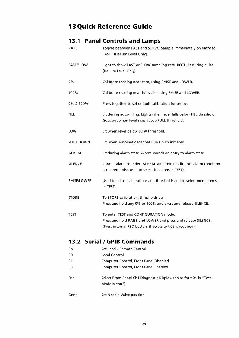
47
13 Quick Reference Guide
13.1 Panel Controls and LampsRATE Toggle between FAST and SLOW. Sample immediately on entry to
FAST. (Helium Level Only).
FAST/SLOW Light to show FAST or SLOW sampling rate. BOTH lit during pulse.
(Helium Level Only).
0% Calibrate reading near zero, using RAISE and LOWER.
100% Calibrate reading near full scale, using RAISE and LOWER.
0% & 100% Press together to set default calibration for probe.
FILL Lit during auto-filling. Lights when level falls below FILL threshold.
Goes out when level rises above FULL threshold.
LOW Lit when level below LOW threshold.
SHUT DOWN Lit when Automatic Magnet Run Down initiated.
ALARM Lit during alarm state. Alarm sounds on entry to alarm state.
SILENCE Cancels alarm sounder. ALARM lamp remains lit until alarm condition
is cleared. (Also used to select functions in TEST).
RAISE/LOWER Used to adjust calibrations and thresholds and to select menu items
in TEST.
STORE To STORE calibration, thresholds etc.:
Press and hold any 0% or 100% and press and release SILENCE.
TEST To enter TEST and CONFIGURATION mode:
Press and hold RAISE and LOWER and press and release SILENCE.
(Press internal RED button, if access to t.06 is required)
13.2 Serial / GPIB CommandsCn Set Local / Remote Control
C0 Local Control
C1 Computer Control, Front Panel Disabled
C3 Computer Control, Front Panel Enabled
Fnn Select Front Panel Ch1 Diagnostic Display. (nn as for t.04 in "Test
Mode Menu")
Gnnn Set Needle Valve position
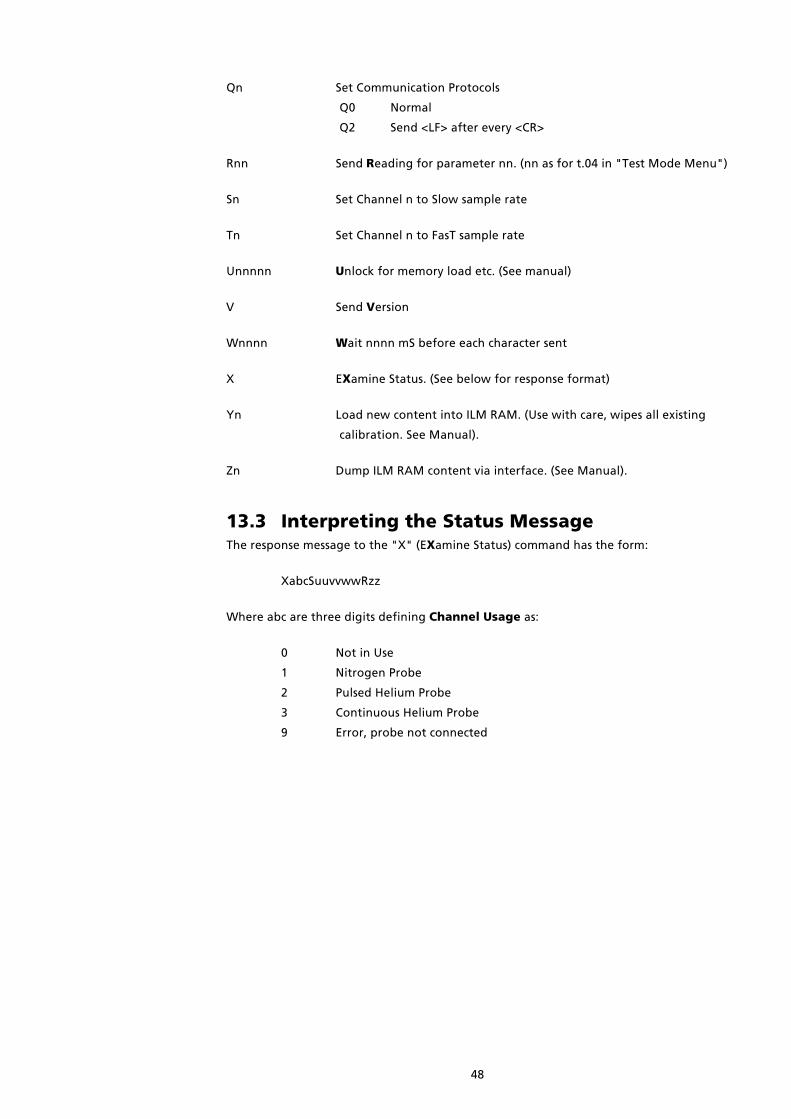
48
Qn Set Communication Protocols
Q0 Normal
Q2 Send <LF> after every <CR>
Rnn Send Reading for parameter nn. (nn as for t.04 in "Test Mode Menu")
Sn Set Channel n to Slow sample rate
Tn Set Channel n to FasT sample rate
Unnnnn Unlock for memory load etc. (See manual)
V Send Version
Wnnnn Wait nnnn mS before each character sent
X EXamine Status. (See below for response format)
Yn Load new content into ILM RAM. (Use with care, wipes all existing
calibration. See Manual).
Zn Dump ILM RAM content via interface. (See Manual).
13.3 Interpreting the Status MessageThe response message to the "X" (EXamine Status) command has the form:
XabcSuuvvwwRzz
Where abc are three digits defining Channel Usage as:
0 Not in Use
1 Nitrogen Probe
2 Pulsed Helium Probe
3 Continuous Helium Probe
9 Error, probe not connected
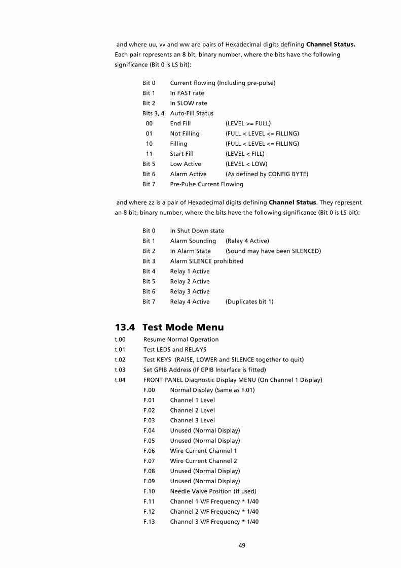
49
and where uu, vv and ww are pairs of Hexadecimal digits defining Channel Status.
Each pair represents an 8 bit, binary number, where the bits have the following
significance (Bit 0 is LS bit):
Bit 0 Current flowing (Including pre-pulse)
Bit 1 In FAST rate
Bit 2 In SLOW rate
Bits 3, 4 Auto-Fill Status
00 End Fill (LEVEL >= FULL)
01 Not Filling (FULL < LEVEL <= FILLING)
10 Filling (FULL < LEVEL <= FILLING)
11 Start Fill (LEVEL < FILL)
Bit 5 Low Active (LEVEL < LOW)
Bit 6 Alarm Active (As defined by CONFIG BYTE)
Bit 7 Pre-Pulse Current Flowing
and where zz is a pair of Hexadecimal digits defining Channel Status. They represent
an 8 bit, binary number, where the bits have the following significance (Bit 0 is LS bit):
Bit 0 In Shut Down state
Bit 1 Alarm Sounding (Relay 4 Active)
Bit 2 In Alarm State (Sound may have been SILENCED)
Bit 3 Alarm SILENCE prohibited
Bit 4 Relay 1 Active
Bit 5 Relay 2 Active
Bit 6 Relay 3 Active
Bit 7 Relay 4 Active (Duplicates bit 1)
13.4 Test Mode Menut.00 Resume Normal Operation
t.01 Test LEDS and RELAYS
t.02 Test KEYS (RAISE, LOWER and SILENCE together to quit)
t.03 Set GPIB Address (If GPIB Interface is fitted)
t.04 FRONT PANEL Diagnostic Display MENU (On Channel 1 Display)
F.00 Normal Display (Same as F.01)
F.01 Channel 1 Level
F.02 Channel 2 Level
F.03 Channel 3 Level
F.04 Unused (Normal Display)
F.05 Unused (Normal Display)
F.06 Wire Current Channel 1
F.07 Wire Current Channel 2
F.08 Unused (Normal Display)
F.09 Unused (Normal Display)
F.10 Needle Valve Position (If used)
F.11 Channel 1 V/F Frequency * 1/40
F.12 Channel 2 V/F Frequency * 1/40
F.13 Channel 3 V/F Frequency * 1/40

50
t.05 CONFIGURE "CFG" each Channel in turn. Specified by a number in the range
0 to 255, made up of 4 parts. The configuration number is obtained by
adding the 4 parts.
Operating MODE
0 Channel not in use
1 Channel used for Nitrogen Level
2 Channel used for Helium Level (Normal Pulsed Operation)
3 Channel used for Helium Level (Continuous Measurement)
Action on FILL condition
0 None (Just lights FILL LED)
4 Activates Channel Relay (for Autofill)
8 Activates Alarm & Relay 4 (SILENCE clears Relay 4)
12 Activates Needle Valve Motor (If fitted)
Action on LOW condition
0 None (Just lights LOW LED)
32 Activates ALARM & Relay 4 (SILENCE clears Relay 4)
64 Light SHUT DOWN, ALARM & Relay 4 (SILENCE disabled)
80 Light SHUT DOWN & Activate Relay 1
96 Light SHUT DOWN & Activate Relay 2
112 Light SHUT DOWN & Activate Relay 3
Automatic FAST / SLOW Switching
0 None (Remains in State set by Operator)
128 Switch to FAST when FILL lights. Switch to SLOW when no rise for 15
minutes.
t.06 Calibrate Internal Current Source, "ICAL"(Only available when Test has been
entered via the internal RED button.) Sets current demand to 100mA. Use
RAISE and LOWER to adjust actual delivered current to this value. Applies to
any channel Configured for Helium use. (Goes to t.08 at exit since wire currents
must be re-set)
t.07 Set nominal Active LENGTH for probe. (Probe calibration will not be possible if
length is not approximately correct).
t.08 Set wire currents for Pre-Pulse "PCu" (Normally not used) and Measuring
Pulse "Cur". Units are mA. Current source must be calibrated by t.06, before
setting t.08.
t.09 Set pulse widths for Pre-Pulse "PrE" (Normally set to 0 to disable pre-pulse)
and measuring pulse "PUL". Units are sec.
t.10 Set intervals between pulses in FAST and SLOW. Note that Units are Seconds
for FAST and Minutes for SLOW.
t.11 Set thresholds for FULL (Filling stops), FILL (Filling starts) and LOW.

51
t.12 Set Needle Valve stepper motor operating mode.
t.13 Set Needle Valve position manually, for leak testing.
t.14 Set wire resistivity (ohms/metre) for helium probes
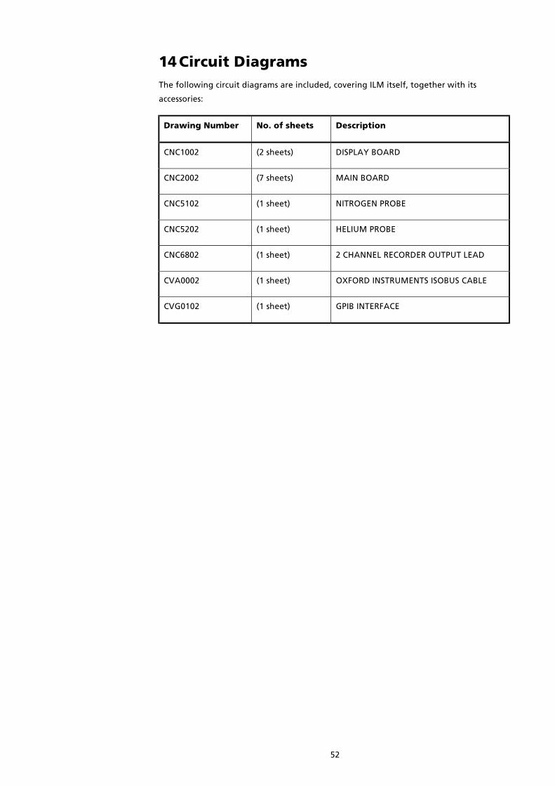
52
14 Circuit DiagramsThe following circuit diagrams are included, covering ILM itself, together with its
accessories:
Drawing Number No. of sheets Description
CNC1002 (2 sheets) DISPLAY BOARD
CNC2002 (7 sheets) MAIN BOARD
CNC5102 (1 sheet) NITROGEN PROBE
CNC5202 (1 sheet) HELIUM PROBE
CNC6802 (1 sheet) 2 CHANNEL RECORDER OUTPUT LEAD
CVA0002 (1 sheet) OXFORD INSTRUMENTS ISOBUS CABLE
CVG0102 (1 sheet) GPIB INTERFACE
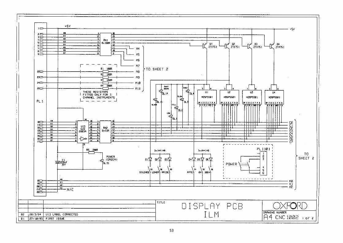
53
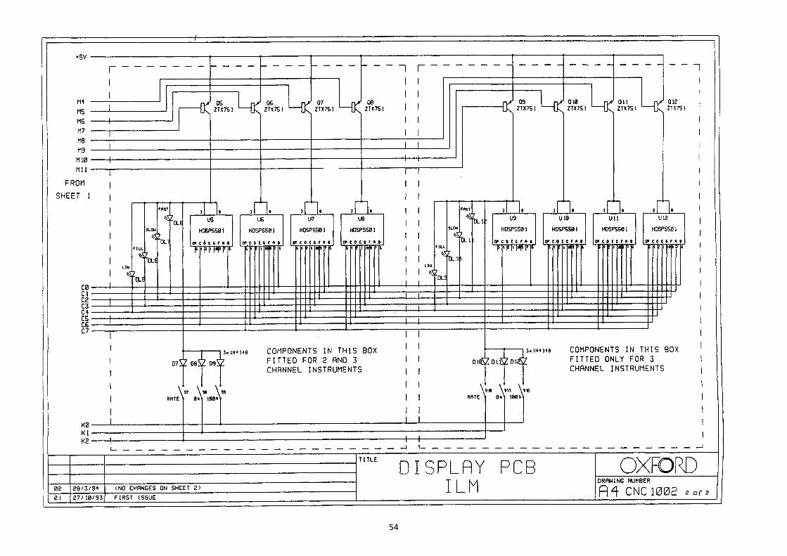
54
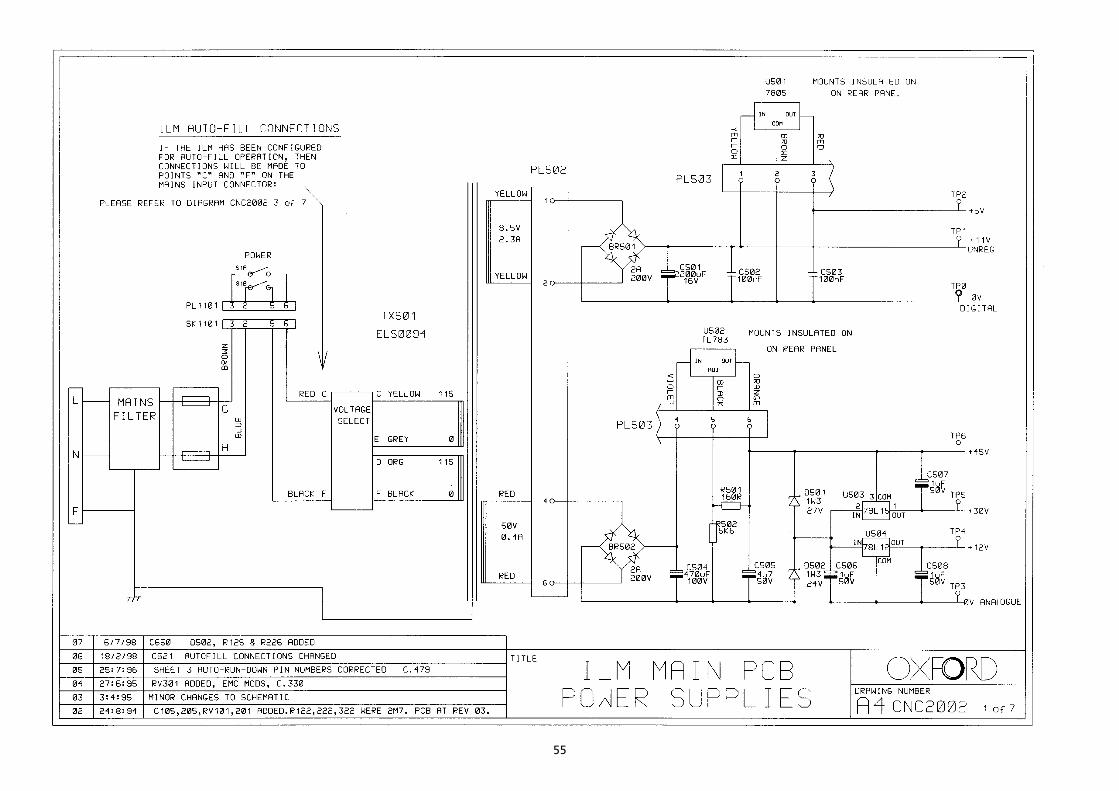
55
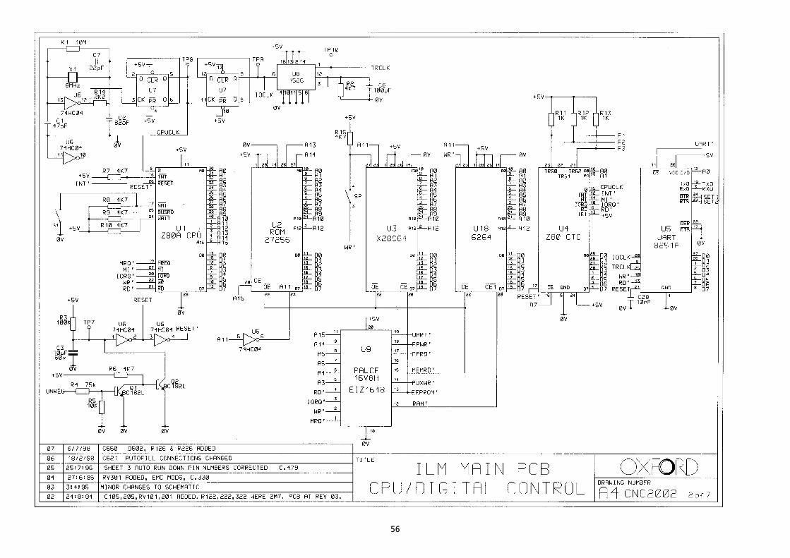
56
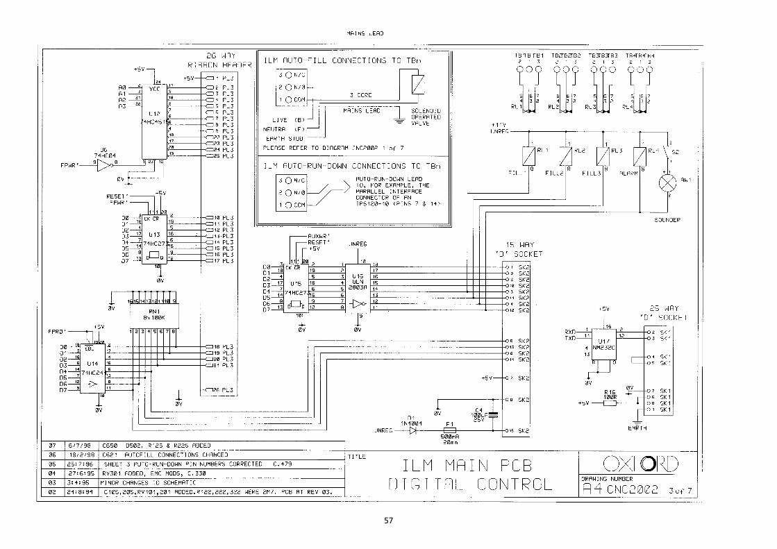
57
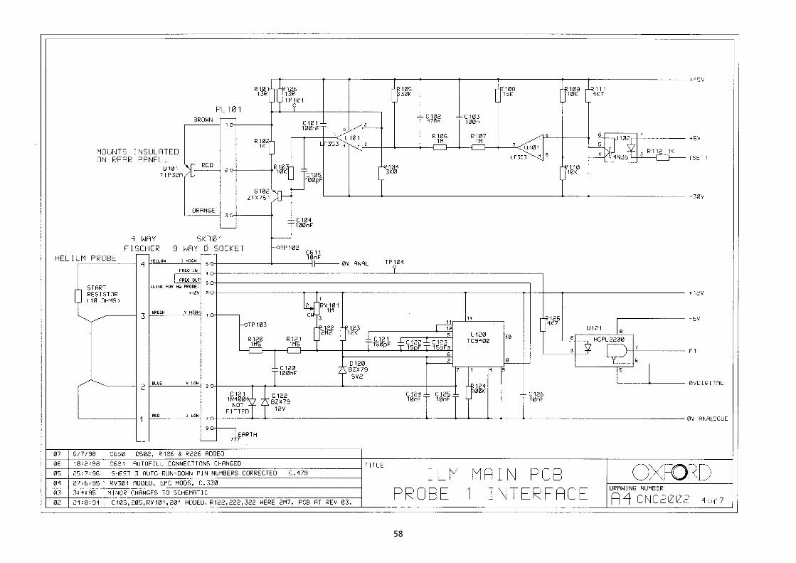
58
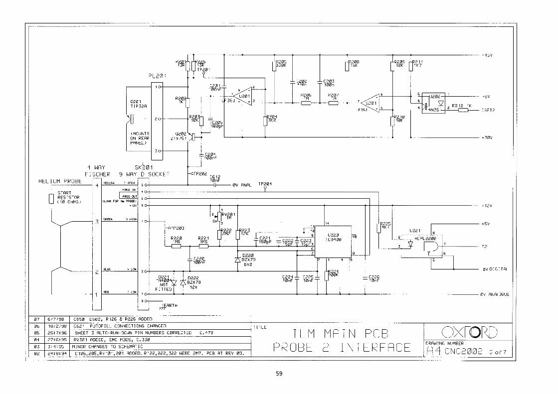
59
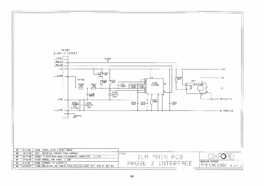
60
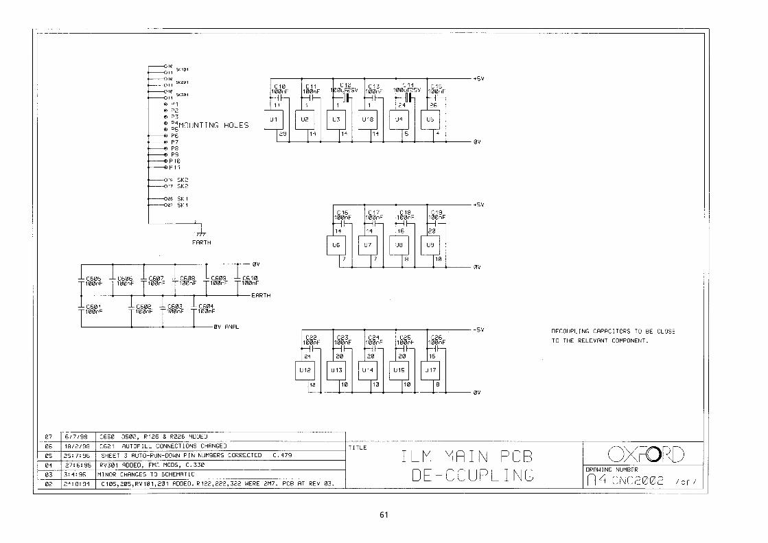
61
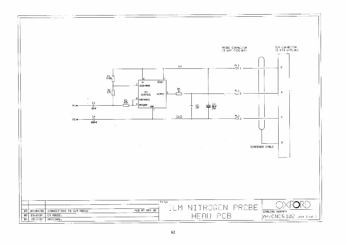
62
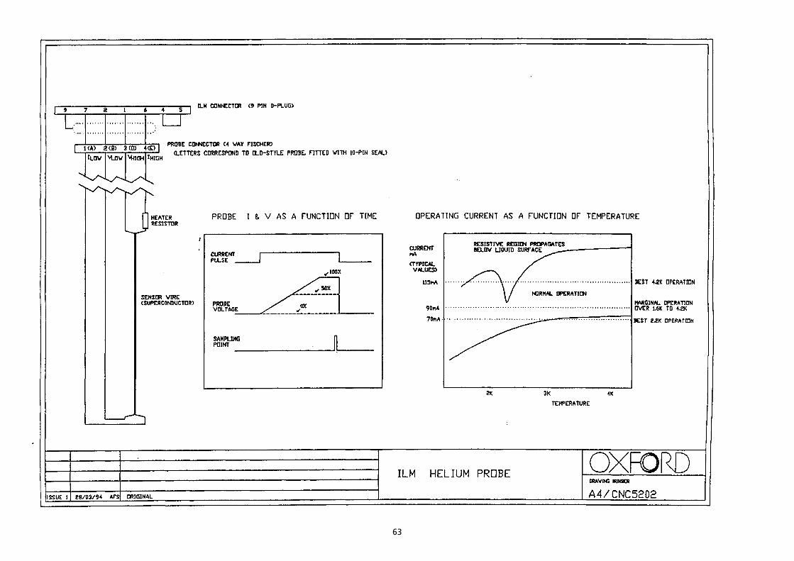
63
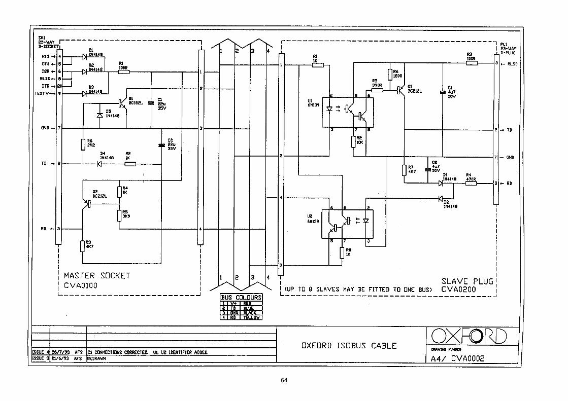
64
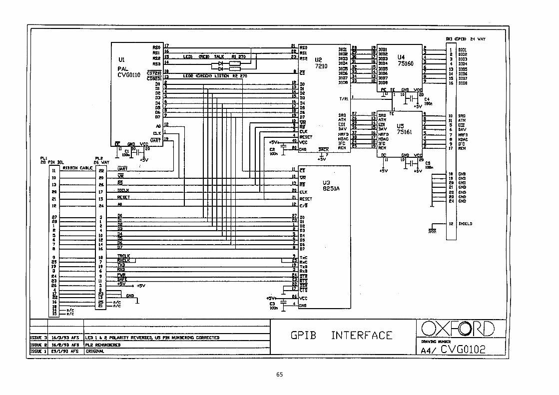
65