Embed Size (px)
Citation preview
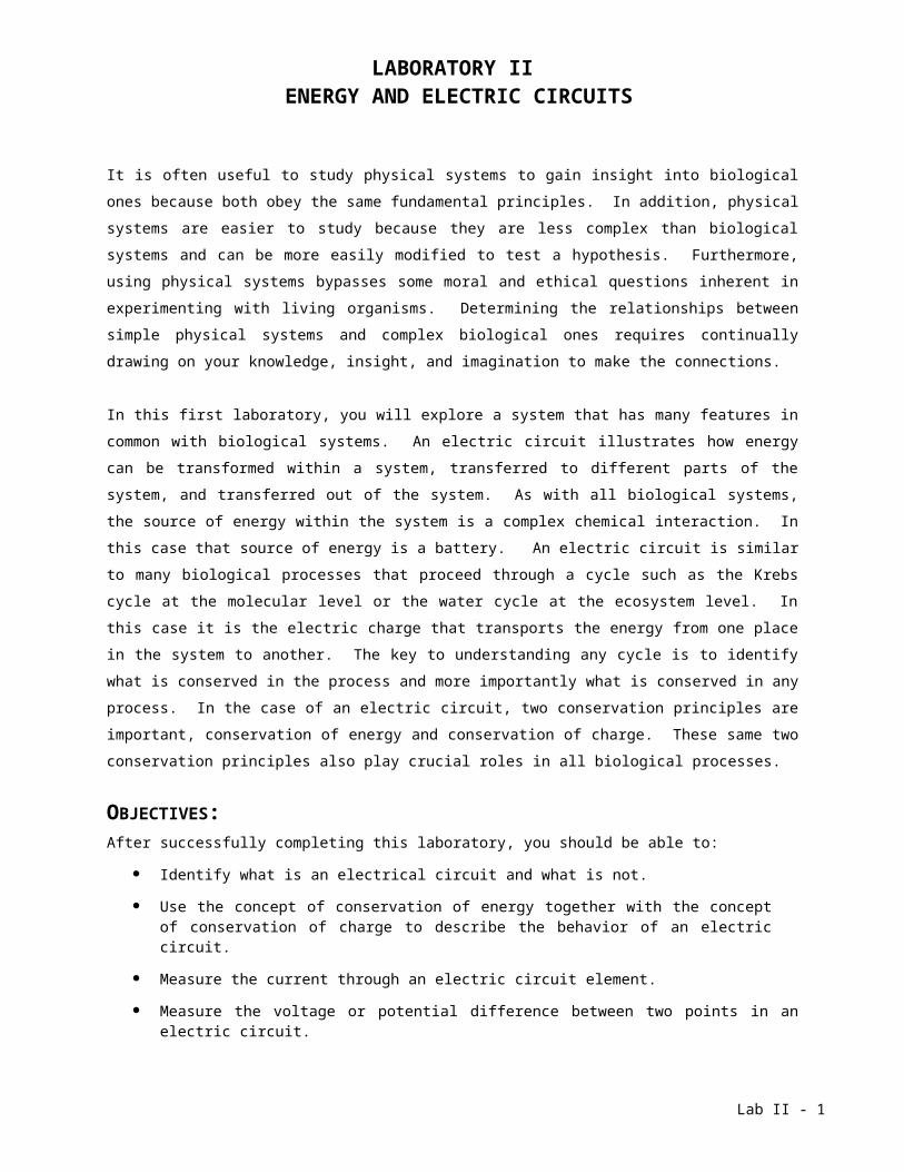
LABORATORY II ENERGY AND ELECTRIC CIRCUITS
It is often useful to study physical systems to gain insight into biological ones because both obey the same fundamental principles. In addition, physical systems are easier to study because they are less complex than biological systems and can be more easily modified to test a hypothesis. Furthermore, using physical systems bypasses some moral and ethical questions inherent in experimenting with living organisms. Determining the relationships between simple physical systems and complex biological ones requires continually drawing on your knowledge, insight, and imagination to make the connections.
In this first laboratory, you will explore a system that has many features in common with biological systems. An electric circuit illustrates how energy can be transformed within a system, transferred to different parts of the system, and transferred out of the system. As with all biological systems, the source of energy within the system is a complex chemical interaction. In this case that source of energy is a battery. An electric circuit is similar to many biological processes that proceed through a cycle such as the Krebs cycle at the molecular level or the water cycle at the ecosystem level. In this case it is the electric charge that transports the energy from one place in the system to another. The key to understanding any cycle is to identify what is conserved in the process and more importantly what is conserved in any process. In the case of an electric circuit, two conservation principles are important, conservation of energy and conservation of charge. These same two conservation principles also play crucial roles in all biological processes.
OBJECTIVES:After successfully completing this laboratory, you should be able to:
Identify what is an electrical circuit and what is not.
Use the concept of conservation of energy together with the concept of conservation of charge to describe the behavior of an electric circuit.
Measure the current through an electric circuit element.
Measure the voltage or potential difference between two points in an electric circuit.
Use a digital multimeter (DMM) to measure various properties of an electric circuit.
Lab II - 1

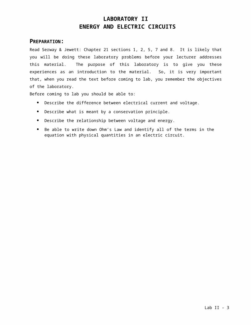
PREPARATION:Read Serway & Jewett: Chapter 21 sections 1, 2, 5, 7 and 8. It is likely that you will be doing these laboratory problems before your lecturer addresses this material. The purpose of this laboratory is to give you these experiences as an introduction to the material. So, it is very important that, when you read the text before coming to lab, you remember the objectives of the laboratory.Before coming to lab you should be able to:
Describe the difference between electrical current and voltage.
Describe what is meant by a conservation principle.
Describe the relationship between voltage and energy.
Be able to write down Ohm’s Law and identify all of the terms in the equation with physical quantities in an electric circuit.
Lab II - 2
PROBLEM #1:ELECTRICAL CONNECTIONS
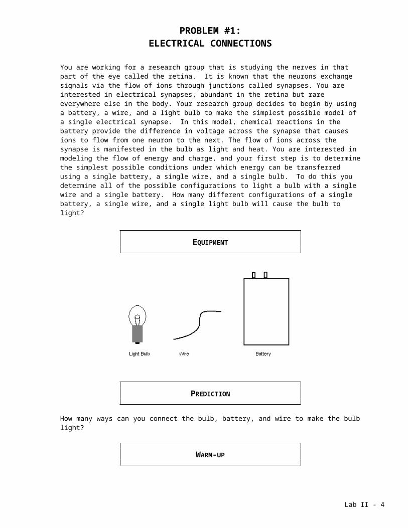
You are working for a research group that is studying the nerves in that part of the eye called the retina. It is known that the neurons exchange signals via the flow of ions through junctions called synapses. You are interested in electrical synapses, abundant in the retina but rare everywhere else in the body. Your research group decides to begin by using a battery, a wire, and a light bulb to make the simplest possible model of a single electrical synapse. In this model, chemical reactions in the battery provide the difference in voltage across the synapse that causes ions to flow from one neuron to the next. The flow of ions across the synapse is manifested in the bulb as light and heat. You are interested in modeling the flow of energy and charge, and your first step is to determine the simplest possible conditions under which energy can be transferred using a single battery, a single wire, and a single bulb. To do this you determine all of the possible configurations to light a bulb with a single wire and a single battery. How many different configurations of a single battery, a single wire, and a single light bulb will cause the bulb to light?
EQUIPMENT
PREDICTION
How many ways can you connect the bulb, battery, and wire to make the bulb light?
WARM-UP
Read Serway & Jewett: sections 21.1, 21.2, 21.5, 21.6.
1. Make a drawing of a single light bulb connected to the battery with a single wire so that the bulb will light. What parts of each object must be touching for the light bulb to light? Is this the only configuration possible? If not, make drawings of other possible configurations.
2. What object in the circuit is the source of energy? Using your drawing(s), describe how the energy gets to the light bulb. What happens to the energy after it gets to the light bulb?
Lab II - 3
PROBLEM #1: ELECTRICAL CONNECTIONS
3. Along which path is the energy carried? Draw arrows to indicate the path of the energy carriers. Are the energy carriers conserved or do they just disappear at the light bulb? If they are conserved, where do they go after delivering energy to the light bulb?
4. What does the battery voltage have to do with this energy? How are the energy carriers related to the electric charge?
5. Using your drawing, describe how conservation of energy applies to the system defined as the light bulb while the bulb is lit. Identify the initial energy of the system, the final energy of the system, any energy entering the system, and any energy leaving the system.
6. Using your drawing, describe how conservation of charge applies to the system defined as the light bulb while the bulb is lit. Identify the initial charge of the system, the final charge of the system, any charge entering the system, and any charge leaving the system
7. Check the drawing(s) you made in question 1. Does it obey conservation of energy? Does it obey conservation of charge? If the answer to any of these questions is no, change your drawing so that the answers are yes.
8. Write down the general properties of an electric circuit that always obeys conservation of energy and conservation of charge an lights the bulb.
EXPLORATION
Look closely at the inside and the outside of a bulb. Draw what you see. How are parts inside of the bulb connected to the outside of the bulb? If you can’t see the connection, make a reasonable guess based on what you do see. What part of the bulb do you think actually lights? What parts of the bulb do you think conduct electricity and what parts do not?
Connect the bulb, battery, and wire as drawn in the warm-up questions. Does the bulb light? If not, try another configuration until you find one that does light. Draw all of the configurations that do not work as well as the ones that do.
Check which part of the bulb lights. Does it agree with what you thought initially?
Can the positive and negative ends of the battery be switched without affecting the operation of the circuit? Can the two ends of the bulb be switched? Are there any parts that cannot be switched? Write down a plan to systematically check all configurations you think might light the bulb.
Lab II - 4
PROBLEM #1: ELECTRICAL CONNECTIONS
MEASUREMENT
Connect the battery, bulb, and wire according to the plan that you wrote down in your Exploration section. Carefully make a drawing of each way you connect the items and the result of whether or not the bulb lights. Also write down the comparative bulb brightness for each configuration.
ANALYSIS
Examine your pictures of situations where the bulb lights and compare them with pictures of situations where the bulb did not light. Also compare the brightness of the bulb in each situation. Write down a general rule for connecting the objects together so that the bulb will always light. What is important and what makes no difference? Estimate how well you can determine relative bulb brightness. Can you tell the difference between a bulb lighting and not lighting?
CONCLUSION
What are the necessary conditions for energy transfer in an electric circuit? How many ways were you able to connect the bulb, wire, and battery to make energy transfer possible? What do these connections have in common? What is different among them? What are the general requirements for a simple working circuit? Compare your results to your predictions.
Lab II - 5
PROBLEM #2QUALITATIVE CIRCUIT ANALYSIS
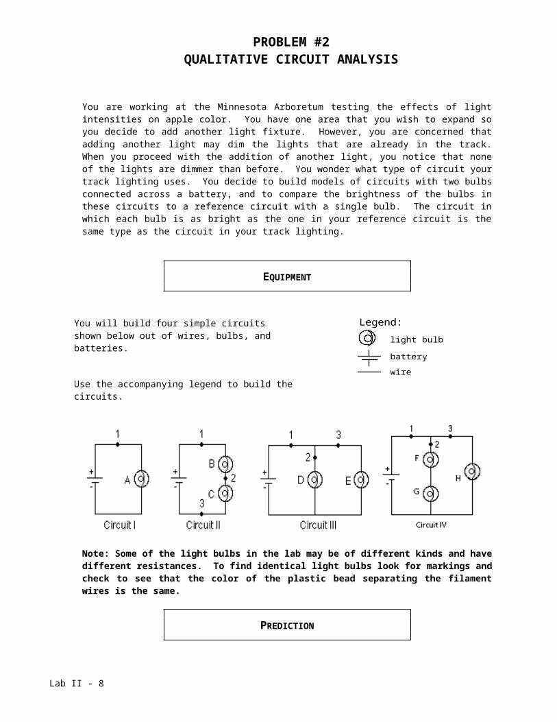
You are working at the Minnesota Arboretum testing the effects of light intensities on apple color. You have one area that you wish to expand so you decide to add another light fixture. However, you are concerned that adding another light may dim the lights that are already in the track. When you proceed with the addition of another light, you notice that none of the lights are dimmer than before. You wonder what type of circuit your track lighting uses. You decide to build models of circuits with two bulbs connected across a battery, and to compare the brightness of the bulbs in these circuits to a reference circuit with a single bulb. The circuit in which each bulb is as bright as the one in your reference circuit is the same type as the circuit in your track lighting.
EQUIPMENT
You will build four simple circuits shown below out of wires, bulbs, and batteries.
Use the accompanying legend to build the circuits.
Legend:
light bulb
battery
wire
Note: Some of the light bulbs in the lab may be of different kinds and have different resistances. To find identical light bulbs look for markings and check to see that the color of the plastic bead separating the filament wires is the same.
PREDICTION
Restate the problem. Rank, in order of brightness, the bulbs A, B, C, D, and E from the brightest to the dimmest (use the symbol ‘=’ for "same brightness as" and the symbol ‘ >’ for "brighter than"). Write down your reasoning.
Lab II - 6
PROBLEM #2: Qualitative Circuit Analysis
EXPLORATION
Reference Circuit IConnect Circuit I to use as a reference. Observe the brightness of bulb A. Replace the bulb with another one and again observe the brightness. Repeat until you have determined the brightness of all your bulbs when they are connected into the same type of circuit. If the bulbs are identical, they should have the same brightness.Note: Pay attention to large differences you may observe, rather than minor differences that may occur if two "identical" bulbs are, in fact, not quite identical. How can you test whether minor differences are due to manufacturing irregularities?Circuit IIConnect Circuit II. Compare the brightness of bulbs B and C. What can you conclude from this observation about the amount of current through each bulb?Is current "used up" in the first bulb, or is the current the same through both bulbs? Try switching bulbs B and C. Based on your observation, what can you infer about the current at points 1, 2, and 3?How does the brightness of bulb A (Circuit I) compare to the brightness of bulbs B and C (Circuit II)? What can you infer about the current at point 1 in each of the two circuits?Circuit IIIConnect Circuit III. Compare the brightness of bulbs D and E. What can you conclude from this observation about the amount of current through each bulb?Describe the flow of current around the entire circuit. What do your observations suggest about the way the current through the battery divides and recombines at junctions where the circuit splits into two branches? How does the current at point 1 compare with the currents at points 2 and 3?How does the brightness of bulb A (Circuit I) compare to the brightness of bulbs D and E (Circuit III)? What can you infer about the current at point 1 in each of the two circuits?Circuit IVConnect Circuit IV. Compare the brightness of bulbs F and G with that of H. What can you conclude from this observation about the amount of current through each bulb?Describe the flow of current around the entire circuit. What do your observations suggest about the way the current through the battery divides and recombines at junctions where the circuit splits into two branches? How does the current at point 1 compare with the currents at points 2 and 3?How does the brightness of bulb B and C compare to the brightness of bulbs G and H? What can you infer about the current at point 1 in each of the two circuits?Comparing the four circuits, does the amount of current at point 1 appear to remain constant or to depend on the number of bulbs and how they are connected?
Lab II - 7
PROBLEM #2: Qualitative Circuit Analysis
CONCLUSIONS
Rank the actual brightness of the bulbs. How did this compare to your prediction? Make sure you adequately describe what you mean in your comparisons, i.e. “the same brightness as”, “brighter than”, “dimmer than”. What type of circuit is used in your track lighting? Circuit II is called a series circuit and Circuit III is called a parallel circuit.
Can you use conservation of energy and conservation of current to explain your results? The rate that energy is output from a bulb is equal to the potential difference (voltage) across the bulb times the current through the bulb. Does a battery supply a constant current or a constant potential difference to circuits?
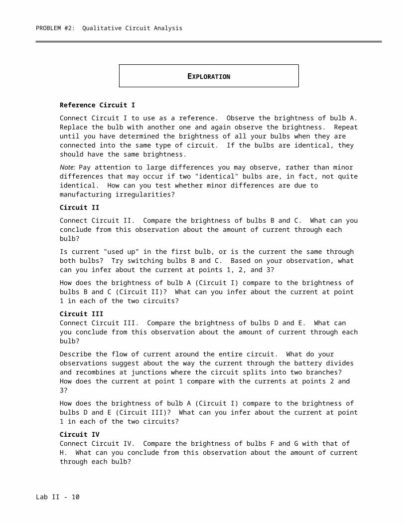
To check your understanding, rank the brightness of the bulbs in the following circuits.
Use the lab equipment to see if your answer is correct.
Lab II - 8

PROBLEM #3QUALITATIVE CIRCUIT ANALYSIS B
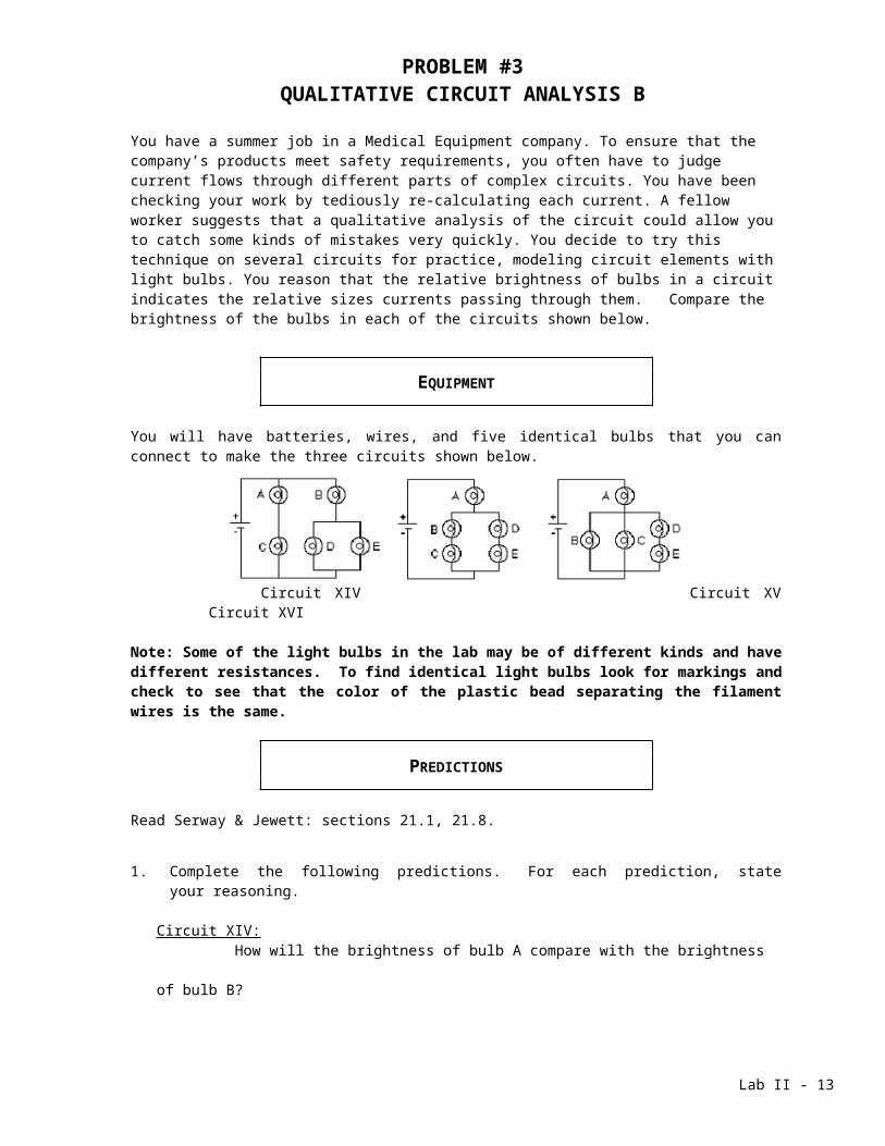
You have a summer job in a Medical Equipment company. To ensure that the company’s products meet safety requirements, you often have to judge current flows through different parts of complex circuits. You have been checking your work by tediously re-calculating each current. A fellow worker suggests that a qualitative analysis of the circuit could allow you to catch some kinds of mistakes very quickly. You decide to try this technique on several circuits for practice, modeling circuit elements with light bulbs. You reason that the relative brightness of bulbs in a circuit indicates the relative sizes currents passing through them. Compare the brightness of the bulbs in each of the circuits shown below.
EQUIPMENT
You will have batteries, wires, and five identical bulbs that you can connect to make the three circuits shown below.
Circuit XIV Circuit XV Circuit XVI
Note: Some of the light bulbs in the lab may be of different kinds and have different resistances. To find identical light bulbs look for markings and check to see that the color of the plastic bead separating the filament wires is the same.
PREDICTIONS
Read Serway & Jewett: sections 21.1, 21.8.
1. Complete the following predictions. For each prediction, state your reasoning.
Circuit XIV:How will the brightness of bulb A compare with the brightness of bulb B?
How will the brightness of bulb B compare with the brightness of bulb D?How will the brightness of bulb C compare with the brightness of bulb D?
Circuit XV:How will the brightness of bulb A compare with the brightness of bulb B?How will the brightness of bulb B compare with the brightness of bulb C?How will the brightness of bulb B compare with the brightness of bulb D?
Lab II - 9
PROBLEM #3: Qualitative Circuit Analysis B
Circuit XVI:How will the brightness of bulb A compare with the brightness of bulb B?How will the brightness of bulb B compare with the brightness of bulb C?How will the brightness of bulb B compare with the brightness of bulb D?
2. Using equations in your text for finding equivalent resistances and your conceptual understanding of circuits, predict the relative brightness of bulb A in the three circuits.
EXPLORATION
Set up each circuit and observe the brightness of the bulbs. How can you test whether minor differences you observe are due to manufacturing irregularities in the "identical" bulbs?
MEASUREMENT
Coordinate with other groups to compare the brightness of bulb A in each of the three circuits.
If necessary, use a DMM to measure the current through bulb A in each of the three circuits (see Appendix D).
CONCLUSION
Quantitative circuit analysis results from applying conservation of energy (Kirchhoffʹs loop rule) and conservation of charge (Kirchhoffʹs junction rule) to series and/or parallel configurations. For each circuit, write the corresponding equation(s).
Lab II - 10
PROBLEM #4RESISTORS AND LIGHT BULBS
Talking with a friend about the role of electric circuits in biological systems, you realize that a light bulb may not be a good model for biological electrical energy transfer. The light bulb is a useful laboratory tool because it is easy to observe differences in the rate of energy transfer by observing its brightness. However, to give off light, the bulb filament must be raised to a temperature well above that of any biological system. There is a common electrical device called a resistor that transfers energy out of the electric circuit without the extreme behavior of a bulb. For this reason, the resistor might be a better object to model biological processes such as those in which an electric current results from the motion of ions through a cellular membrane. As a first step in determining the similarities and differences of the electrical properties of light bulbs and resistors, you draw a graph of the relationship between the voltage across a light bulb to the current through the light bulb and compare it to a resistor. You decide to check your graphs by making the relevant measurements in the laboratory. Determine how the current through a light bulb depends on the voltage across it. How does that relationship compare to that for a resistor?
EQUIPMENT
You will have wires, a power supply, a digital multimeter (DMM), a light bulb, and a resistor. The power supply has the same function as a battery, to supply energy to the circuit by maintaining a constant voltage or potential difference. Because this voltage is not the result of chemical reactions, it is easy to change the voltage across the power supply within some range.
PREDICTIONS
Sketch a graph describing your expectations of the relationship between the voltage across a resistor and the current through the resistor. On your graph also sketch your expectation for the behavior of a light bulb.
WARM-UP
Read Serway & Jewett: sections 21.1, 21.2.
1. Draw a picture of a circuit containing one battery, one resistor, and two wires. On the picture show how you would insert a device to measure the voltage across the resistor. Now redraw the picture of the battery, resistor, and wires showing how you would insert a device to measure the current through the resistor.
2. Draw a graph of voltage across an object vs. the current through the object as given by Ohm’s Law. How does one determine the resistance of the object from this graph?
3. As more current goes through a light bulb, it gets brighter because it gets hotter. Do you expect the increasing temperature to change the bulb’s resistance? If so, how? Draw a graph of voltage across a light bulb versus current through a light bulb that shows your expectation of its resistance.
Lab II - 11
PROBLEM #4: Resistors and Light Bulbs
EXPLORATION
WARNING: You will be working with a power supply that can generate large electric currents. Improper use can cause painful burns. To avoid danger, the power should be turned OFF and you should WAIT at least one minute before any wires are disconnected from or connected to the power supply. Never grasp a wire by its metal end.
Connect your light bulb to the power supply in a circuit. Go through the range of voltages and observe the brightness change of the bulb. Decide on a range of voltages to use for your measurements. Looking at your prediction graph, determine how many measurements you should take and at what voltages. How many points are necessary to check your prediction when the bulb is dim? When the bulb is bright?
Read Appendix D and try out the different functions of the digital multimeter (DMM). Make sure that your DMM is set to measure a current or is set to measure a voltage depending on how it is connected in your circuit. Using a DMM to measure a current in a voltage-measuring configuration may damage the meter.
MEASUREMENT
Follow the measurement plan that you decided upon in the Exploration section for the light bulb and the same plan for your resistor. Make sure that your DMM is connected so that it measures either the voltage across the light bulb (or resistor) or the current through it. To make sure you are making reasonable measurements, check the resistance of your resistor by the following independent techniques. Compare these determinations with each other and with the results of your graph.
1. Use the color code on the resistor (see Appendix D) to determine the resistance as calibrated at the factory. What is the uncertainty in this value?
2. Use the DMM set to ohms to directly measure the resistance of the resistor. To do this the resistor must be disconnected form the circuit. What is the uncertainty in this value?
ANALYSIS
Make a graph of voltage versus current for your resistor and light bulb. Use the graph to determine the resistance of the resistor as a function of voltage (or current). Use the graph to determine the resistance of the light bulb as a function of voltage (or current).
CONCLUSION
Do the resistor and light bulb have the same electrical behavior? If so, what are their resistances? If not, is there a range of voltages where they have approximately the same behavior? Did your prediction match your results? Explain why or why not.
Lab II - 12
PROBLEM #4: Resistors and Light Bulbs
What are possible sources of systematic uncertainty? (see Appendix C) Does the equipment contribute any? Do you? Be specific in explaining how and why.
Lab II - 13
PROBLEM #5SHORT CIRCUITS
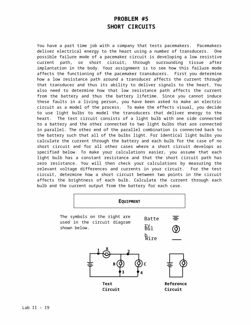
You have a part time job with a company that tests pacemakers. Pacemakers deliver electrical energy to the heart using a number of transducers. One possible failure mode of a pacemaker circuit is developing a low resistive current path, or short circuit, through surrounding tissue after implantation in the body. Your assignment is to see how this failure mode affects the functioning of the pacemaker transducers. First you determine how a low resistance path around a transducer affects the current through that transducer and thus its ability to deliver signals to the heart. You also need to determine how that low resistance path affects the current from the battery and thus the battery lifetime. Since you cannot induce these faults in a living person, you have been asked to make an electric circuit as a model of the process. To make the effects visual, you decide to use light bulbs to model the transducers that deliver energy to the heart. The test circuit consists of a light bulb with one side connected to a battery and the other connected to two light bulbs that are connected in parallel. The other end of the parallel combination is connected back to the battery such that all of the bulbs light. For identical light bulbs you calculate the current through the battery and each bulb for the case of no short circuit and for all other cases where a short circuit develops as specified below. To make your calculations easier, you assume that each light bulb has a constant resistance and that the short circuit path has zero resistance. You will then check your calculations by measuring the relevant voltage differences and currents in your circuit. For the test circuit, determine how a short circuit between two points in the circuit affects the brightness of each bulb. Calculate the current through each bulb and the current output from the battery for each case.
EQUIPMENT
The symbols on the right are used in the circuit diagram shown below.
Note: Some of the light bulbs in the lab may be of different kinds and have different resistances. To find identical light bulbs look for markings and check to see that the color of the plastic bead separating the filament wires is the same.
Lab II - 14
Battery
Bulb
Wire
A
B C
1 2
3 4
Test Circuit Reference Circuit
PROBLEM #5: Short Circuits
PREDICTIONS
Determine the brightness of each of the bulbs when a wire is attached from point 1 to point 2 by calculating the current through each bulb in terms of the battery voltage and bulb resistance. Calculate the current output by the battery as a function of the battery voltage and bulb resistance.
Determine the brightness of each of the bulbs when a wire is attached from point 2 to point 3 by calculating the current through each bulb in terms of the battery voltage and bulb resistance. Calculate the current output by the battery as a function of the battery voltage and bulb resistance.
Determine the brightness of each of the bulbs when a wire is attached from point 1 to point 3 by calculating the current through each bulb in terms of the battery voltage and bulb resistance. Calculate the current output by the battery as a function of the battery voltage and bulb resistance.
Determine the brightness of each of the bulbs when a wire is attached from point 2 to point 4 by calculating the current through each bulb in terms of the battery voltage and bulb resistance. Calculate the current output by the battery as a function of the battery voltage and bulb resistance.
WARM-UP
Read Serway & Jewett: sections 21.1, 21.2, 21.6, 21.7, 21.8.
1. Draw the diagram of the test circuit. Compare the potential differences across pairs of points (taken from the four points labeled) with each other and with the voltage across the battery. Label the voltage across each bulb. Compare the voltage across each bulb with the voltage between the labeled points. Explain why you think it is smaller, equal, or larger than the voltage across the battery.
2. Draw and label the current through each wire on the circuit diagram. Use conservation of charge to determine how these currents are related.
3. Using your circuit diagram follow an energy carrier (say a positive charge) from the battery around a complete circuit back to the battery. Use conservation of energy to write down an equation (or equations) relating the voltage differences across each bulb. You may need to consider more than one path for the charge to take.
4. Write down equations relating the voltage difference across each bulb to the current through that bulb using Ohm’s law as an approximation
5. Using the equations from questions 2, 3, 4 can you solve for the current through the battery? If not, find a different path around a complete circuit and write down the voltage equation for that path. Continue this process of choosing paths and writing
Lab II - 15
PROBLEM #5: Short Circuits
down voltage equations until you have enough equations to solve for the current through the battery.
6. How is the brightness of a bulb related to the rate of energy transferred to the bulb? Write down an equation showing how the current through the bulb determines its brightness. Write down an equation showing how the voltage across the bulb determines its brightness.
7. Draw a wire between point 1 and point 2. How does the voltage across each bulb change? How does this voltage change affect the brightness of each bulb?
8. Now repeat questions 2 and 3 with this new circuit.
9. Repeat the above steps for the other short circuit configurations.
EXPLORATION
WARNING: A short circuit is what happens any time a very low-resistance path (like a wire, or other piece of metal) is provided between points in a circuit that are at different potentials, like the terminals of a battery or power supply. Short circuits can destroy equipment and injure people! Always avoid short circuits in other circuits! Short circuits damage equipment by causing larger currents in a circuit than they are designed for. These currents can cause intense heat and damage to nearby circuit elements or measuring devices. Only apply the short circuit for a small amount of time.
Build the test circuit and make sure all of the bulbs light. Try touching a wire to make a short circuit for a very small amount of time. Determine the shortest time necessary to make a reliable observation of the bulb brightness. Use this technique to make your measurements.Decide how you will insert a DMM in your circuit to measure the current from your battery. Make sure the DMM has the correct setting before you put it in the circuit to prevent damaging the meter. Does the DMM significantly affect your circuit? Look at the brightness of the bulbs before and after you insert the DMM. Determine how long you will need to keep a short circuit connected to make an accurate measurement with your DMM.Decide on the best way to make the set of measurements that you need.
Lab II - 16
PROBLEM #5: Short Circuits
MEASUREMENT
Follow the measurement plan that you decided upon in the Exploration section using the reference circuit for brightness comparisons and the DMM for current measurements.
ANALYSIS
Examine your circuit diagrams for the three bulbs with each short circuit and compare the brightness of the bulb in each situation. Estimate how well you can determine relative bulb brightness. Does this qualitative brightness determination agree with your quantitative current measurements?Does the resistance of your DMM affect the current measurements in each case? Does introducing the DMM to measure the current through a bulb have a noticeable effect on the brightness of that bulb? Estimate the size of this effect.
CONCLUSION
Did your predictions match your observed results? Explain your answers. What effects might such malfunctions have on human patients?
Lab II - 17
PROBLEM #6QUANTITATIVE CIRCUIT ANALYSIS
You work with a team building networks of circuits designed to imitate the behavior of networks of neurons in the brain. You are assigned the job of tuning the parameters of a circuit that represents a feedback loop within a single neuron. You run into trouble in your calculations, and decide to test some of your assumptions about variations in the current supplied to your feedback circuit, using the model circuit shown below. Determine the current through each resistor in the circuit shown.
EQUIPMENT
Build the circuit shown to the right with wires, resistors, and a voltage source (batteries or a power supply).
You will have a digital multimeter (DMM) for measuring resistance, voltages, and currents. Circuit
PREDICTION
Write an expression for the current through each resistor in the circuit, in terms of the resistances and voltages labeled in the circuit diagram.
WARM-UP
Read Serway & Jewett: sections 21.1, 21.2, 21.6, 21.7, 21.8.1. Draw and label a circuit diagram, showing all voltages and resistors. Sometimes
you may need to redraw the given circuit to help yourself see which resistors are in series and which are in parallel. For this problem, the voltages and the resistances are the known quantities and the currents in the resistors are the unknowns.
2. Assign a separate current for each branch of the circuit, indicating each current on the diagram. Identify the number of circuit paths (loops) and label them on the diagram.
3. Apply conservation of current to each point in the circuit at which wires come together (a junction). Use conservation of energy to get the sum of the potential differences across all of the elements in each loop, ensuring your signs are correct. Does the potential difference increase or decrease across each circuit element, in the direction you have chosen to traverse the loop? Use Ohm's law to get the potential difference across each resistor. Check that the number of linear equations that you wrote above matches the number of unknowns.
Lab II - 18
PROBLEM #6: Quantitative Circuit Analysis
4. Complete the calculations and write your solution. Simplify your equations as much as possible, but be warned that your final solutions may look quite complicated.
EXPLORATION
If you have not used the digital multimeter (DMM), read Appendix D and get familiar with its different operations.
Build the circuit. How can you tell if there is current flowing through the circuit? What happens to the current at each junction? What is the resistance of each resistor? What is the potential difference provided by each of the batteries? What is the potential difference across each resistor? Use the DMM to check your answers to each of these questions.
Complete your measurement plan.
MEASUREMENT
Measure the resistance of the resistors, the current flowing through each resistor, and the potential difference provided by each battery in the circuits. So that you can check your measurements, measure the potential difference across each resistor.
ANALYSIS
Calculate the current through each resistor from your prediction equations, using your measured values of the resistance of each resistor and voltage of each battery. Compare those results to the measured values of each current.
CONCLUSION
Did your measured and predicted values of the currents through the resistors agree? If not, explain the discrepancy. As a check for the consistency of your measurements, calculate the potential difference across each resistor using the currents that you measured. Compare these values with the potential difference across each resistor that you measured with the DMM.
Lab II - 19
PROBLEM #7QUANTITATIVE CIRCUIT ANALYSIS B
You again work with a team building networks of circuits designed to imitate the behavior of networks of neurons in the brain. You are assigned the job of tuning the parameters of a circuit that represents a feedback loop within a single neuron. You run into trouble in your calculations, and decide to test some of your assumptions about variations in the current supplied to your feedback circuit, using the model circuit shown below. Determine the current through each resistor in the circuit shown.
EQUIPMENT
You will have wires, resistors, and batteries or a power supply to build a circuit shown to the right.
You will have a digital multimeter (DMM) to measure resistances, voltages, and currents.
PREDICTION
Derive formulas to calculate the current through each of resistors in Circuit XIII as a function of voltages of the batteries and resistances involved in the circuit.
WARM-UP QUESTIONS
1. Draw and label a circuit diagram showing all voltages and resistors. Sometimes you may need to redraw the given circuit to help yourself see which resistors are in series and which are in parallel. For this problem, the voltages and the resistors are the known quantities and the currents in the resistors are the unknowns.
2. Assign a separate current for each leg of the circuit, indicating each current on the diagram. Identify the number of circuit paths (loops) and label them on the diagram.
3. Apply conservation of current to each point in the circuit at which wires come together (a junction). Use conservation of energy to get the sum of the potential differences across all of the elements in each loop, ensuring your signs are correct. Does the potential difference increase or decrease across each circuit element, in the direction you have chosen to traverse the loop? Use Ohm's law to get the potential difference across each resistor.
Check that the number of linear equations that you have now matches the number of unknowns.
Lab II - 20
PROBLEM #7: Quantitative Circuit Analysis B
4. Complete the calculations and write your solution. Simplify your equations as much as possible, but be warned that your final solutions may look quite complicated.
EXPLORATION
To become familiar with a DMM and various modes of its operation, read Appendix D.Build Circuit XIII. How can you tell if there is current flowing through the circuit? What happens to the current at each junction? What is the resistance of each resistor? What is the potential difference provided by each of the batteries? What is the potential difference across each resistor? Use the DMM to check your answers to each of these questions.Complete your measurement plan.
MEASUREMENT
Measure the resistance of each of the three resistors, as well as the currents flowing through each of them. Measure the potential difference provided by each battery. So that you can check your measurements, measure the potential difference across each resistor.
ANALYSIS
Calculate the current through each resistor from your prediction equations, using your measured values of the resistance of each resistor and voltage of each battery. Compare those results to the measured values of each current.
CONCLUSIONS
Did your measured and predicted values of the currents through the resistors agree? If not, explain the discrepancy.As a check for the consistency of your measurements, calculate the potential difference across each resistor using the currents that you measured. Compare these values with the potential difference across each resistor that you measured with the DMM.
Lab II - 21
CHECK YOUR UNDERSTANDING
1. What would happen to the brightness of bulb A in the circuit below if more bulbs were added parallel to bulbs B and C?
In household circuits, a fuse or circuit breaker is in the position occupied by bulb A, why?
2. Rank Circuits I through IV from the largest current at point 1 to the smallest current at point 1. Explain your reasoning.
3. Predict what will happen to the brightness of bulbs A, B, C and D if bulb E were removed from its socket. Explain your reasoning.
Lab II - 22
CHECK YOUR UNDERSTANDING
4. For the circuit below, determine the current in each resistor.
+-
+- 12 V24 V
8
6
3624
12
5. For the circuit below, determine the value for R such that the current I3 is 0.1A with the indicated direction.
+- 3 V R
20
+-
6 V
5
I3
What is the value for R that will give a current I3 = 0.1 A, but in the opposite direction to what is shown?
Lab II - 23
PHYSICS 1202 LABORATORY REPORTLaboratory III
Name and ID#:
Date performed: Day/Time section meets:
Lab Partners' Names:
Problem # and Title: Lab Instructor's Initials:
Grading Checklist Points
LABORATORY JOURNAL:
PREDICTIONS(individual predictions and warm-up completed in journal before each lab session)
LAB PROCEDURE(measurement plan recorded in journal, tables and graphs made in journal as data is collected, observations written in journal)
PROBLEM REPORT:*
ORGANIZATION(clear and readable; logical progression from problem statement through conclusions; pictures provided where necessary; correct grammar and spelling; section headings provided; physics stated correctly)
DATA AND DATA TABLES(clear and readable; units and assigned uncertainties clearly stated)
RESULTS(results clearly indicated; correct, logical, and well-organized calculations with uncertainties indicated; scales, labels and uncertainties on graphs; physics stated correctly)
CONCLUSIONS(comparison to prediction & theory discussed with physics stated correctly ; possible sources of uncertainties identified; attention called to experimental problems)
TOTAL(incorrect or missing statement of physics will result in a maximum of 60% of the total points achieved; incorrect grammar or spelling will result in a maximum of 70% of the total points achieved)
BONUS POINTS FOR TEAMWORK(as specified by course policy)
* An "R" in the points column means to rewrite that section only and return it to your lab instructor within two days of the return of the report to you.
Lab II - 24