Embed Size (px)
Citation preview

Remote control by telephone
K6501
ILLUSTRATED ASSEMBLY MANUAL H6501IP-1
Total solder points: 338 Difficulty level: beginner 1 2 3 4 5 advanced
Operate your appliances from
anywhere with a simple phone call.
2
Features:
Controlled from a touch tone phone (DTMF). Unit gives audible feedback of output status. Adjustable security code. Pickup after 4 or 7 rings possible. Room for three output relays, one relay included. Input to monitor the status of a switch from a distance.
Specifications:
• Relay outputs : 240V/5A • Power supply : 12VAC or DC / 300mA. • Dimensions : 105x130
Features & Specifications
3
Assembly hints
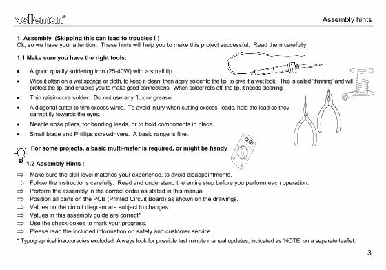
1. Assembly (Skipping this can lead to troubles ! ) Ok, so we have your attention. These hints will help you to make this project successful. Read them carefully. 1.1 Make sure you have the right tools: • A good quality soldering iron (25-40W) with a small tip.
• Wipe it often on a wet sponge or cloth, to keep it clean; then apply solder to the tip, to give it a wet look. This is called ‘thinning’ and will protect the tip, and enables you to make good connections. When solder rolls off the tip, it needs cleaning.
• Thin raisin-core solder. Do not use any flux or grease.
• A diagonal cutter to trim excess wires. To avoid injury when cutting excess leads, hold the lead so they cannot fly towards the eyes.
• Needle nose pliers, for bending leads, or to hold components in place.
• Small blade and Phillips screwdrivers. A basic range is fine.
For some projects, a basic multi-meter is required, or might be handy
1.2 Assembly Hints :
⇒ Make sure the skill level matches your experience, to avoid disappointments. ⇒ Follow the instructions carefully. Read and understand the entire step before you perform each operation. ⇒ Perform the assembly in the correct order as stated in this manual ⇒ Position all parts on the PCB (Printed Circuit Board) as shown on the drawings. ⇒ Values on the circuit diagram are subject to changes. ⇒ Values in this assembly guide are correct* ⇒ Use the check-boxes to mark your progress. ⇒ Please read the included information on safety and customer service
* Typographical inaccuracies excluded. Always look for possible last minute manual updates, indicated as ‘NOTE’ on a separate leaflet.
0.000
4
Assembly hints
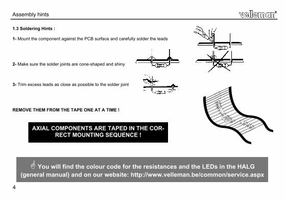
1.3 Soldering Hints :
1- Mount the component against the PCB surface and carefully solder the leads
2- Make sure the solder joints are cone-shaped and shiny
3- Trim excess leads as close as possible to the solder joint
REMOVE THEM FROM THE TAPE ONE AT A TIME !
AXIAL COMPONENTS ARE TAPED IN THE COR-RECT MOUNTING SEQUENCE !
You will find the colour code for the resistances and the LEDs in the HALG (general manual) and on our website: http://www.velleman.be/common/service.aspx
5
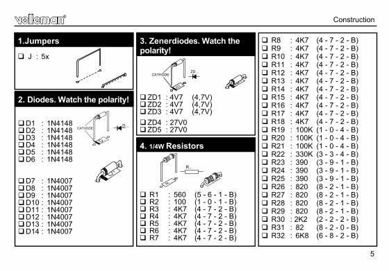
R1 : 560 (5 - 6 - 1 - B) R2 : 100 (1 - 0 - 1 - B) R3 : 4K7 (4 - 7 - 2 - B) R4 : 4K7 (4 - 7 - 2 - B) R5 : 4K7 (4 - 7 - 2 - B) R6 : 4K7 (4 - 7 - 2 - B) R7 : 4K7 (4 - 7 - 2 - B)
4. 1/4W Resistors
R...
Construction
J : 5x 1.Jumpers R8 : 4K7 (4 - 7 - 2 - B)
R9 : 4K7 (4 - 7 - 2 - B) R10 : 4K7 (4 - 7 - 2 - B) R11 : 4K7 (4 - 7 - 2 - B) R12 : 4K7 (4 - 7 - 2 - B) R13 : 4K7 (4 - 7 - 2 - B) R14 : 4K7 (4 - 7 - 2 - B) R15 : 4K7 (4 - 7 - 2 - B) R16 : 4K7 (4 - 7 - 2 - B) R17 : 4K7 (4 - 7 - 2 - B) R18 : 4K7 (4 - 7 - 2 - B) R19 : 100K (1 - 0 - 4 - B) R20 : 100K (1 - 0 - 4 - B) R21 : 100K (1 - 0 - 4 - B) R22 : 330K (3 - 3 - 4 - B) R23 : 390 (3 - 9 - 1 - B) R24 : 390 (3 - 9 - 1 - B) R25 : 390 (3 - 9 - 1 - B) R26 : 820 (8 - 2 - 1 - B) R27 : 820 (8 - 2 - 1 - B) R28 : 820 (8 - 2 - 1 - B) R29 : 820 (8 - 2 - 1 - B) R30 : 2K2 (2 - 2 - 2 - B) R31 : 82 (8 - 2 - 0 - B) R32 : 6K8 (6 - 8 - 2 - B)
D1 : 1N4148 D2 : 1N4148 D3 : 1N4148 D4 : 1N4148 D5 : 1N4148 D6 : 1N4148
D7 : 1N4007 D8 : 1N4007 D9 : 1N4007 D10 : 1N4007 D11 : 1N4007 D12 : 1N4007 D13 : 1N4007 D14 : 1N4007
2. Diodes. Watch the polarity!
D...CATHODE
ZD1 : 4V7 (4,7V) ZD2 : 4V7 (4,7V) ZD3 : 4V7 (4,7V)
ZD4 : 27V0 ZD5 : 27V0
3. Zenerdiodes. Watch the polarity!
ZD...CATHODE
6
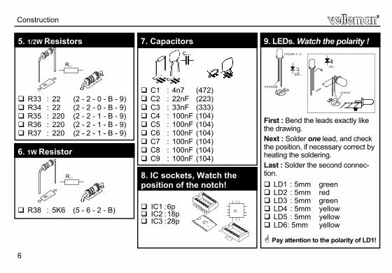
IC1 : 6p IC2 : 18p IC3 : 28p
8. IC sockets, Watch the position of the notch!
R33 : 22 (2 - 2 - 0 - B - 9) R34 : 22 (2 - 2 - 0 - B - 9) R35 : 220 (2 - 2 - 1 - B - 9) R36 : 220 (2 - 2 - 1 - B - 9) R37 : 220 (2 - 2 - 1 - B - 9)
5. 1/2W Resistors
R...
R38 : 5K6 (5 - 6 - 2 - B)
6. 1W Resistor
R...
C1 : 4n7 (472) C2 : 22nF (223) C3 : 33nF (333) C4 : 100nF (104) C5 : 100nF (104) C6 : 100nF (104) C7 : 100nF (104) C8 : 100nF (104) C9 : 100nF (104)
7. Capacitors
Construction
First : Bend the leads exactly like the drawing.
Next : Solder one lead, and check the position, if necessary correct by heating the soldering.
Last : Solder the second connec-tion.
LD1 : 5mm green LD2 : 5mm red LD3 : 5mm green LD4 : 5mm yellow LD5 : 5mm yellow LD6 : 5mm yellow
Pay attention to the polarity of LD1!
9. LEDs. Watch the polarity !
LD...
CATHODE7mm
COLOR= 2...5
LD...
CATHODE
7
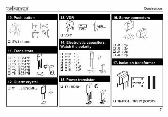
T1 : BC547B T2 : BC547B T3 : BC547B T4 : BC547B T5 : BC547B T6 : BC547B
11. Transistors
X1 : 3,5795MHz X...
12. Quartz crystal
SW1 : 1 pos.
10. Push button
VDR1
13. VDR
C10 : 1µF C11 : 1µF C12 : 1µF C13 : 1µF C14 : 10µF C15 : 10µF
14. Electrolytic capacitors. Watch the polarity !
C...
J1 : 2p J2 : 2p J3 : 2p J4 : 2p
16. Screw connectors
T7 : BD681
15. Power transistor
TRAFO1 : TRS1/1 (600/600)
17. Isolation transformer
Construction
8
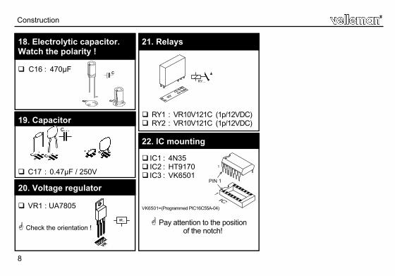
IC1 : 4N35 IC2 : HT9170 IC3 : VK6501
VK6501=(Programmed PIC16C55A-04)
Pay attention to the position of the notch!
22. IC mounting
PIN 1
1
C16 : 470µF
18. Electrolytic capacitor. Watch the polarity !
C...
C17 : 0.47µF / 250V
19. Capacitor
VR1 : UA7805 Check the orientation !
20. Voltage regulator
VR...
Construction
RY1 : VR10V121C (1p/12VDC) RY2 : VR10V121C (1p/12VDC)
21. Relays
RY...RY...
9
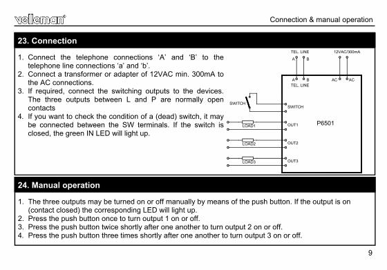
1. Connect the telephone connections ‘A’ and ‘B’ to the telephone line connections ‘a’ and ‘b’.
2. Connect a transformer or adapter of 12VAC min. 300mA to the AC connections.
3. If required, connect the switching outputs to the devices. The three outputs between L and P are normally open contacts
4. If you want to check the condition of a (dead) switch, it may be connected between the SW terminals. If the switch is closed, the green IN LED will light up.
23. Connection
Connection & manual operation
TEL. LINE 12VAC/300mA
LOAD1
LOAD2
LOAD3
SWITCHSWITCH
OUT1
OUT2
OUT3
ACA B AC
P6501
A B
TEL. LINE
1. The three outputs may be turned on or off manually by means of the push button. If the output is on (contact closed) the corresponding LED will light up.
2. Press the push button once to turn output 1 on or off. 3. Press the push button twice shortly after one another to turn output 2 on or off. 4. Press the push button three times shortly after one another to turn output 3 on or off.
24. Manual operation
10
Code setting
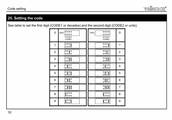
See table to set the first digit (CODE1 or decades) and the second digit (CODE2 or units).
25. Setting the code
D C B ACODE1
SW20
1
2
3
4
5
6
7
8
9
SW2
CODE2B ACD
9
8
7
6
5
4
3
2
1
0
11
Normally the device is set to pick up the phone after ± 8 rings. If, however, you would like the device to pick up the phone sooner (after ± 3 rings), the manual operating push button should be held pressed before switching on the power supply. Output 1 will switch on by way of confirmation.
26. Setting the number of rings
Setting the numbers of rings
12
ESTABLISHING THE CONNECTION: 1. Call the phone number to which the remote control is connected. 2. After about 3 or 8 rings the remote control will answer. The red "ON LINE" LED on the device will flash. 3. A few seconds after picking up you will hear the condition of the outputs. First de switch input, then output
1, output 2, and output 3 in that order. A double tone indicates that the condition is ON, whereas a single tone indicates that the condition is OFF.
RETRIEVING INFORMATION FROM OUTPUTS OR INPUT: Enter: code1, code2 and then 0 0. Now you will once again hear the condition of the input and of the outputs. This procedure may be repeated as often as you like.
SWITCHING A PARTICULAR OUTPUT ON: Enter: code1, code2, output number, 1. After a few seconds you will hear the condition of the input and of the outputs. Example: Suppose you want to switch output 2 on and that your code is 43. Enter the following digits: 4-3-2-1.
SWITCHING A PARTICULAR OUTPUT OFF: Enter: code1, code2, output number, 0. The condition of the input and of the outputs will be repeated immediately. Example: Suppose you want to switch output 2 off and that your code is 43. Enter the following digits: 4-3-2-0.
NOTES: If you do not press a button within 20 seconds, the connec-tion will be terminated automatically. If you enter a wrong code, you will hear an alarm tone. After that, you still have two chances to enter the correct code. If the correct code has not been entered after three attempts, the device will terminate the connection.
27. Use
Use
13
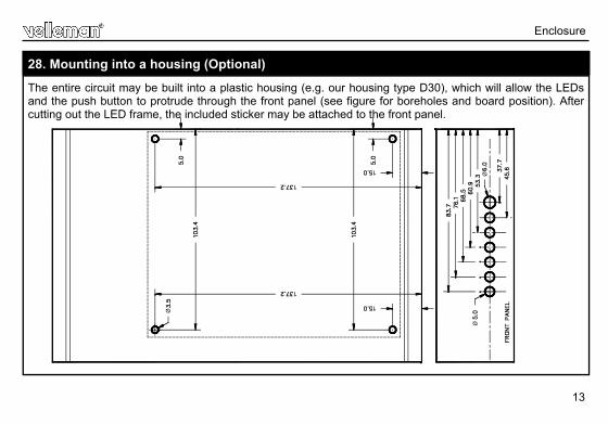
28. Mounting into a housing (Optional)
The entire circuit may be built into a plastic housing (e.g. our housing type D30), which will allow the LEDs and the push button to protrude through the front panel (see figure for boreholes and board position). After cutting out the LED frame, the included sticker may be attached to the front panel.
Enclosure
Ø
Ø
Ø
14
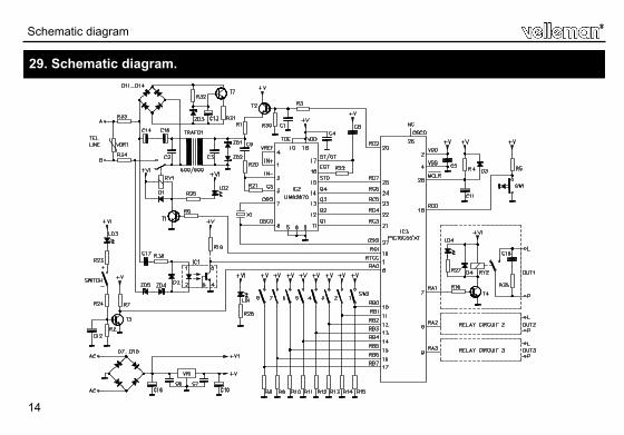
29. Schematic diagram.
Schematic diagram
15
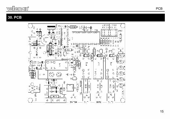
PCB
30. PCB

5 4 1 0 3 2 9 2 8 9 4 3 0
Modifications and typographical errors reserved © Velleman nv. H6501IP - 2004 - ED1_rev.2
VELLEMAN NV Legen Heirweg 33, 9890 Gavere
Belgium - Europe