Embed Size (px)
Citation preview

K8028
ILLUSTRATED ASSEMBLY MANUAL H8028IP-2
Total solder points: 145 Difficulty level: beginner 1 2 3 4 5 advanced
NOISE
SUPPRESSED
ACCORDING TO
EN55015
Multifunctional dimmer for light
bulbs & halogen lighting
MULTIFUNCTIONAL DIMMER
H8028IP'2-rev3.pubpage 1
Monday, August 27, 2012 10:04
2
Specifications:
Microprocessor technology. 13 operating modes including toggle switch, dimmer, staircase timer, slow-on / slow-off dimmer, timer, etc… Suited for both resistive and inductive loads: (Incandecent lightbulbs, halogen lighting, low voltage halogen
lighting with wirewound transformers, …) “Soft start”-function stretches bulb life. Auto shutdown-function switches off the unit when a load error is detected (e.g. too inductive or no load). Push button control allows parallelling of buttons to enable control from several remote locations. Two delay timers with learn mode (5s – 2h). No memory loss in case of power failure. On board fuse and mode selection push button. LED status indication (mode,error, dim status,...) Features: AC power: 110-125 to 220-240VAC, 50/60Hz. Auto netfrequency detection (50/60Hz.) Max. load: 2,5A (300W / 120V - 600W / 230V) Dimensions: 100x82x36mm (4”x3.3”x1,4”)
Features & Specifications
Attention: This unit is not suited for electronic transformers.
H8028IP'2-rev3.pubpage 2
Monday, August 27, 2012 10:04

3
Assembly hints
1. Assembly (Skipping this can lead to troubles ! ) Ok, so we have your attention. These hints will help you to make this project successful. Read them carefully. 1.1 Make sure you have the right tools:
A good quality soldering iron (25-40W) with a small tip. Wipe it often on a wet sponge or cloth, to keep it clean; then apply solder to the tip, to give it a wet look. This is called ‘thinning’ and will protect the tip,
and enables you to make good connections. When solder rolls off the tip, it needs cleaning. Thin raisin-core solder. Do not use any flux or grease. A diagonal cutter to trim excess wires. To avoid injury when cutting excess leads, hold the lead so they cannot fly towards the eyes. Needle nose pliers, for bending leads, or to hold components in place. Small blade and Phillips screwdrivers. A basic range is fine.
For some projects, a basic multi-meter is required, or might be handy
1.2 Assembly Hints :
Make sure the skill level matches your experience, to avoid disappointments. Follow the instructions carefully. Read and understand the entire step before you perform each operation. Perform the assembly in the correct order as stated in this manual Position all parts on the PCB (Printed Circuit Board) as shown on the drawings. Values on the circuit diagram are subject to changes, the values in this assembly guide are correct* Use the check-boxes to mark your progress. Please read the included information on safety and customer service * Typographical inaccuracies excluded. Always look for possible last minute manual updates, indicated as ‘NOTE’ on a separate leaflet.
0.000
1.3 Soldering Hints :
1- Mount the component against the PCB surface and carefully solder the leads
2- Make sure the solder joints are cone-shaped and shiny 3- Trim excess leads as close as possible to the solder joint
H8028IP'2-rev3.pubpage 3
Monday, August 27, 2012 10:04

DO NOT BLINDLY FOLLOW THE ORDER OF THE COMPONENTS ONTO THE TAPE. ALWAYS CHECK THEIR VALUE ON THE PARTS LIST!
REMOVE THEM FROM THE TAPE ONE AT A TIME !
H8028IP'2-rev3.pubpage 4
Monday, August 27, 2012 10:04
5
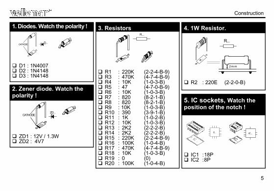
R1 : 220K (2-2-4-B-9) R3 : 470K (4-7-4-B-9) R4 : 10K (1-0-3-B) R5 : 47 (4-7-0-B-9) R6 : 10K (1-0-3-B) R7 : 820 (8-2-1-B) R8 : 820 (8-2-1-B) R9 : 10K (1-0-3-B) R10 : 390 (3-9-1-B) R11 : 1K (1-0-2-B) R12 : 10K (1-0-3-B) R13 : 2K2 (2-2-2-B) R14 : 2K2 (2-2-2-B) R15 : 220K (2-2-4-B-9) R16 : 100K (1-0-4-B) R17 : 470K (4-7-4-B-9) R18 : 10K (1-0-3-B) R19 : 0 (0) R20 : 100K (1-0-4-B)
3. Resistors R...
Construction
D1 : 1N4007 D2 : 1N4148 D3 : 1N4148
1. Diodes. Watch the polarity !
D...CATHODE
ZD1 : 12V / 1.3W ZD2 : 4V7
2. Zener diode. Watch the polarity !
ZD...CATHODE
R2 : 220E (2-2-0-B)
4. 1W Resistor.
IC1 : 18P
IC2 : 8P
5. IC sockets, Watch the position of the notch !
R...
2m m
H8028IP'2-rev3.pubpage 5
Monday, August 27, 2012 10:04
6
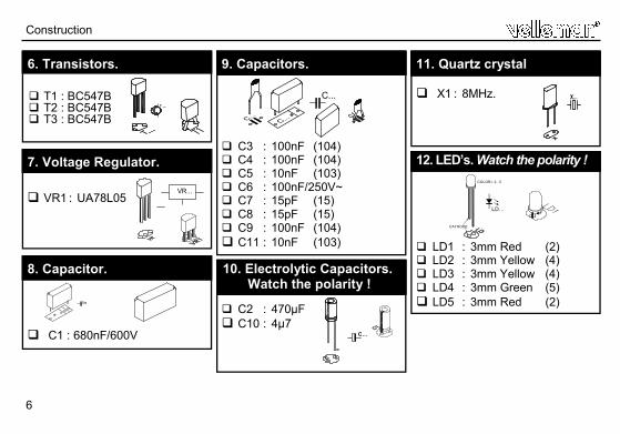
T1 : BC547B T2 : BC547B T3 : BC547B
6. Transistors.
VR1 : UA78L05
7. Voltage Regulator.
VR...
C1 : 680nF/600V
8. Capacitor.
C3 : 100nF (104) C4 : 100nF (104) C5 : 10nF (103) C6 : 100nF/250V~ C7 : 15pF (15) C8 : 15pF (15) C9 : 100nF (104) C11 : 10nF (103)
9. Capacitors.
C2 : 470µF C10 : 4µ7
10. Electrolytic Capacitors. Watch the polarity !
C...
X1 : 8MHz.
11. Quartz crystal
X...
LD1 : 3mm Red (2) LD2 : 3mm Yellow (4) LD3 : 3mm Yellow (4) LD4 : 3mm Green (5) LD5 : 3mm Red (2)
12. LED’s. Watch the polarity ! COLOR= 2...5
LD...
CATHODE
Construction
C...
H8028IP'2-rev3.pubpage 6
Monday, August 27, 2012 10:04
7
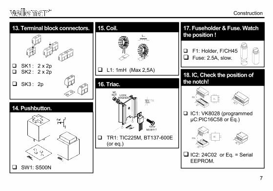
SK1 : 2 x 2p SK2 : 2 x 2p SK3 : 2p
13. Terminal block connectors.
Construction
SW1: S500N
14. Pushbutton.
L1: 1mH (Max 2,5A)
15. Coil. L...
TR1: TIC225M, BT137-600E
(or eq.)
16. Triac.
10mmM3 BOLT
M3NUT LOCK
WASHER
F1: Holder, F/CH45 Fuse: 2.5A, slow.
17. Fuseholder & Fuse. Watch the position !
IC1: VK8028 (programmed µC:PIC16C58 or Eq.)
IC2: 24C02 or Eq. = Serial EEPROM.
18. IC, Check the position of the notch!
H8028IP'2-rev3.pubpage 7
Monday, August 27, 2012 10:04
8
Connection diagram
Connection diagram
ENA
BLE
LD
5
MA
X
LD1
U
P.
LD2
DO
WN
LD
3 M
IN
LD4
K80
28
F1
SK2
SK1
LOA
D A
C P
OW
ER
INPU
T
SK3
INC
AN
DEC
ENT
LIG
HTB
ULB
M
AIN
S
PRIM
SEC
LO
W V
OLT
AGE
HA
LOG
EN B
ULB
.
PUSH
BU
TTO
N (S
)
H8028IP'2-rev3.pubpage 8
Monday, August 27, 2012 10:04
9
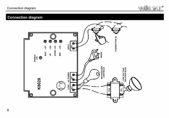
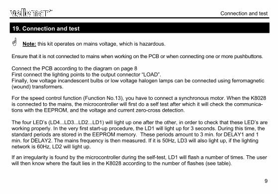
Note: this kit operates on mains voltage, which is hazardous. Ensure that it is not connected to mains when working on the PCB or when connecting one or more pushbuttons. Connect the PCB according to the diagram on page 8 First connect the lighting points to the output connector “LOAD”. Finally, low voltage incandescent bulbs or low voltage halogen lamps can be connected using ferromagnetic (wound) transformers. For the speed control function (Function No.13), you have to connect a synchronous motor. When the K8028 is connected to the mains, the microcontroller will first do a self test after which it will check the communica-tions with the EEPROM, and the voltage and current zero-cross detection. The four LED’s (LD4...LD3...LD2...LD1) will light up one after the other, in order to check that these LED’s are working properly. In the very first start-up procedure, the LD1 will light up for 3 seconds. During this time, the standard periods are stored in the EEPROM memory. These periods amount to 3 min. for DELAY1 and 1 min. for DELAY2. The mains frequency is then measured. If it is 50Hz, LD3 will also light up, if the lighting network is 60Hz, LD2 will light up. If an irregularity is found by the microcontroller during the self-test, LD1 will flash a number of times. The user will then know where the fault lies in the K8028 according to the number of flashes (see table).
19. Connection and test
Connection and test
H8028IP'2-rev3.pubpage 9
Monday, August 27, 2012 10:04
10
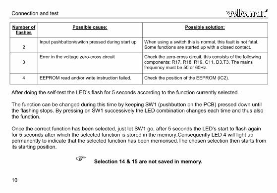
After doing the self-test the LED’s flash for 5 seconds according to the function currently selected. The function can be changed during this time by keeping SW1 (pushbutton on the PCB) pressed down until the flashing stops. By pressing on SW1 successively the LED combination changes each time and thus also the function. Once the correct function has been selected, just let SW1 go, after 5 seconds the LED’s start to flash again for 5 seconds after which the selected function is stored in the memory.Consequently LED 4 will light up permanently to indicate that the selected function has been memorised.The chosen selection then starts from its starting position.
Selection 14 & 15 are not saved in memory.
Number of flashes
Possible cause: Possible solution:
2
Input pushbutton/switch pressed during start up When using a switch this is normal, this fault is not fatal. Some functions are started up with a closed contact.
3
Error in the voltage zero-cross circuit Check the zero-cross circuit, this consists of the following components: R17, R18, R19, C11, D3,T3. The mains frequency must be 50 or 60Hz.
4 EEPROM read and/or write instruction failed. Check the position of the EEPROM (IC2).
Connection and test
H8028IP'2-rev3.pubpage 10
Monday, August 27, 2012 10:04
11
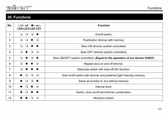
No. ( = off = on ) LD4-LD3-LD2-LD1
Function
1 On/off switch.
2 Pushbutton dimmer with memory.
3 Slow ON dimmer (switch controlled).
4 Slow OFF dimmer (switch controlled).
5 Slow ON/OFF (switch controlled). (Equal to the operation of our former K2657).
6 Repeat slow on and off dimmer.
7 Staircase switch with slow off dim function.
8 Soft on/off switch with dimmer and preferred light intensity memory.
9 Same as function 8, but without memory.
10 Interval timer.
11 Switch, slow on/off and dimmer combination.
12 Moment contact.
20. Functions
Functions
H8028IP'2-rev3.pubpage 11
Monday, August 27, 2012 10:04
12
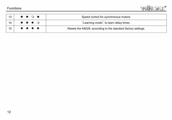
13 Speed control for synchronous motors.
14 “Learning mode”, to learn delay times.
15 Resets the K8028, according to the standard factory settings.
Functions
H8028IP'2-rev3.pubpage 12
Monday, August 27, 2012 10:04
13
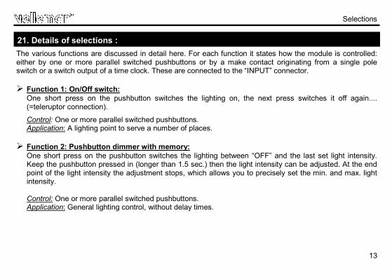
The various functions are discussed in detail here. For each function it states how the module is controlled: either by one or more parallel switched pushbuttons or by a make contact originating from a single pole switch or a switch output of a time clock. These are connected to the “INPUT” connector.
Function 1: On/Off switch:
One short press on the pushbutton switches the lighting on, the next press switches it off again....(=teleruptor connection).
Control: One or more parallel switched pushbuttons. Application: A lighting point to serve a number of places.
Function 2: Pushbutton dimmer with memory:
One short press on the pushbutton switches the lighting between “OFF” and the last set light intensity. Keep the pushbutton pressed in (longer than 1.5 sec.) then the light intensity can be adjusted. At the end point of the light intensity the adjustment stops, which allows you to precisely set the min. and max. light intensity. Control: One or more parallel switched pushbuttons. Application: General lighting control, without delay times.
Selections
21. Details of selections :
H8028IP'2-rev3.pubpage 13
Monday, August 27, 2012 10:04
14
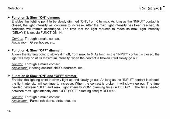
Function 3: Slow “ON” dimmer: Enables the lighting point to be slowly dimmed “ON”, from 0 to max. As long as the “INPUT” contact is closed, the light intensity will continue to increase. After the max. light intensity has been reached, its condition will remain unchanged. The time that the light requires to reach its max. light intensity (DELAY1) is set via FUNCTION 14.
Control: Through a make contact. Application: Greenhouse, etc.
Function 4: Slow “OFF” dimmer: Allows the lighting point to slowly dim off, from max. to 0. As long as the “INPUT” contact is closed, the light will stay on at its maximum intensity, when the contact is broken it will slowly go out.
Control: Through a make contact. Application: Heating cabinet, child’s bedroom, etc.
Function 5: Slow “ON” and “OFF” dimmer: Enables the lighting point to slowly light up and slowly go out. As long as the “INPUT” contact is closed, the light intensity will continue to increase. When the contact is broken it will slowly go out. The time needed between “OFF” and max. light intensity (“ON” dimming time) = DELAY1. The time needed between max. light intensity and “OFF” (“OFF” dimming time) = DELAY2.
Control: Through a make contact. Application: Farms (chickens, birds, etc), etc
Selections
H8028IP'2-rev3.pubpage 14
Monday, August 27, 2012 10:04
15
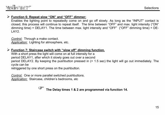
Function 6: Repeat slow “ON” and “OFF” dimmer: Enables the lighting point to repeatedly come on and go off slowly. As long as the “INPUT” contact is closed, this process will continue to repeat itself. The time between “OFF” and max. light intensity (“ON” dimming time) = DELAY1. The time between max. light intensity and “OFF” (“OFF” dimming time) = DE-LAY2. Control: Through a make contact. Application: Lighting for atmosphere, etc.
Function 7: Staircase switch with “slow off” dimming function.
With a short press the light will come on at full intensity for a period DELAY1, after which it slowly goes out over a second period DELAY2. By keeping the pushbutton pressed in (> 1.5 sec) the light will go out immediately. The cycle can be retriggered by one short press on the pushbutton. Control: One or more parallel switched pushbuttons. Application: Staircase, children’s bedrooms, etc
The Delay times 1 & 2 are programmed via function 14.
Selections
H8028IP'2-rev3.pubpage 15
Monday, August 27, 2012 10:04
16
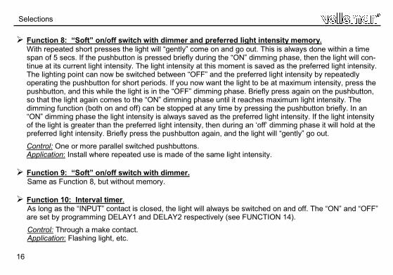
Function 8: “Soft” on/off switch with dimmer and preferred light intensity memory. With repeated short presses the light will “gently” come on and go out. This is always done within a time span of 5 secs. If the pushbutton is pressed briefly during the “ON” dimming phase, then the light will con-tinue at its current light intensity. The light intensity at this moment is saved as the preferred light intensity. The lighting point can now be switched between “OFF” and the preferred light intensity by repeatedly operating the pushbutton for short periods. If you now want the light to be at maximum intensity, press the pushbutton, and this while the light is in the “OFF” dimming phase. Briefly press again on the pushbutton, so that the light again comes to the “ON” dimming phase until it reaches maximum light intensity. The dimming function (both on and off) can be stopped at any time by pressing the pushbutton briefly. In an “ON” dimming phase the light intensity is always saved as the preferred light intensity. If the light intensity of the light is greater than the preferred light intensity, then during an ‘off’ dimming phase it will hold at the preferred light intensity. Briefly press the pushbutton again, and the light will “gently” go out.
Control: One or more parallel switched pushbuttons. Application: Install where repeated use is made of the same light intensity.
Function 9: “Soft” on/off switch with dimmer.
Same as Function 8, but without memory. Function 10: Interval timer.
As long as the “INPUT” contact is closed, the light will always be switched on and off. The “ON” and “OFF” are set by programming DELAY1 and DELAY2 respectively (see FUNCTION 14).
Control: Through a make contact. Application: Flashing light, etc.
Selections
H8028IP'2-rev3.pubpage 16
Monday, August 27, 2012 10:04
17
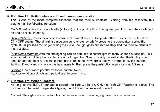
Function 11: Switch, slow on/off and dimmer combination. This is one of the most complete functions that the module contains. Starting from the rest state this setting has the following functions:
On / off switch: For this press briefly (< 1 sec) on the pushbutton. The lighting point is alternately switched on and off at full intensity.
Slow ON / OFF: Press for a period between 1.5 and 3 secs on the pushbutton. This activates the slow ON / OFF setting. The dimming sense can be reversed by briefly pressing the pushbutton during the cycle. If it is pressed for longer during the cycle, the light goes out immediately and the module returns to the rest state.
Pushbutton dimmer: With this the lighting can be held at a constant light intensity chosen at random. This is activated by holding the pushbutton in for longer than 3 secs. during the rest state. The lighting now goes on and off quickly until the pushbutton is released. Now press briefly to immediately put out the lighting. If you want to change the light intensity, then press the pushbutton again for min. 1,5 secs.
Control: One or more parallel switched pushbuttons. Application: General lighting applications, bedroom, etc.
Function 12: Moment contact.
As long as the “INPUT” contact is closed, the light will be on. Only the “soft-ON” function is active. The function can be used to operate a lighting point through an external contact. Control: Through a make contact from an external control source, e.g. timer, micro controller.
Selections
H8028IP'2-rev3.pubpage 17
Monday, August 27, 2012 10:04
18
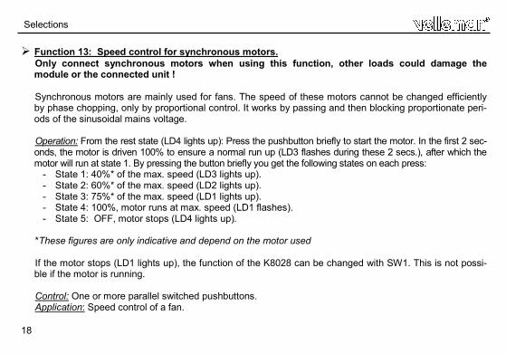
Function 13: Speed control for synchronous motors. Only connect synchronous motors when using this function, other loads could damage the module or the connected unit ! Synchronous motors are mainly used for fans. The speed of these motors cannot be changed efficiently by phase chopping, only by proportional control. It works by passing and then blocking proportionate peri-ods of the sinusoidal mains voltage.
Operation: From the rest state (LD4 lights up): Press the pushbutton briefly to start the motor. In the first 2 sec-onds, the motor is driven 100% to ensure a normal run up (LD3 flashes during these 2 secs.), after which the motor will run at state 1. By pressing the button briefly you get the following states on each press: - State 1: 40%* of the max. speed (LD3 lights up). - State 2: 60%* of the max. speed (LD2 lights up). - State 3: 75%* of the max. speed (LD1 lights up). - State 4: 100%, motor runs at max. speed (LD1 flashes). - State 5: OFF, motor stops (LD4 lights up). *These figures are only indicative and depend on the motor used If the motor stops (LD1 lights up), the function of the K8028 can be changed with SW1. This is not possi-ble if the motor is running. Control: One or more parallel switched pushbuttons. Application: Speed control of a fan.
Selections
H8028IP'2-rev3.pubpage 18
Monday, August 27, 2012 10:04
19
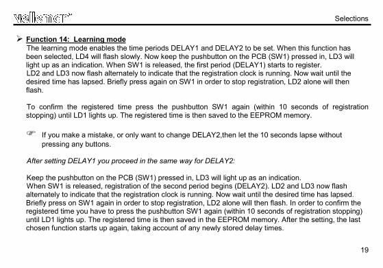
Function 14: Learning mode The learning mode enables the time periods DELAY1 and DELAY2 to be set. When this function has been selected, LD4 will flash slowly. Now keep the pushbutton on the PCB (SW1) pressed in, LD3 will light up as an indication. When SW1 is released, the first period (DELAY1) starts to register. LD2 and LD3 now flash alternately to indicate that the registration clock is running. Now wait until the desired time has lapsed. Briefly press again on SW1 in order to stop registration, LD2 alone will then flash. To confirm the registered time press the pushbutton SW1 again (within 10 seconds of registration stopping) until LD1 lights up. The registered time is then saved to the EEPROM memory. If you make a mistake, or only want to change DELAY2,then let the 10 seconds lapse without
pressing any buttons.
After setting DELAY1 you proceed in the same way for DELAY2: Keep the pushbutton on the PCB (SW1) pressed in, LD3 will light up as an indication. When SW1 is released, registration of the second period begins (DELAY2). LD2 and LD3 now flash alternately to indicate that the registration clock is running. Now wait until the desired time has lapsed. Briefly press on SW1 again in order to stop registration, LD2 alone will then flash. In order to confirm the registered time you have to press the pushbutton SW1 again (within 10 seconds of registration stopping) until LD1 lights up. The registered time is then saved in the EEPROM memory. After the setting, the last chosen function starts up again, taking account of any newly stored delay times.
Selections
H8028IP'2-rev3.pubpage 19
Monday, August 27, 2012 10:04
20
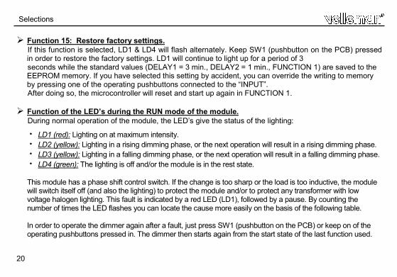
Function 15: Restore factory settings. If this function is selected, LD1 & LD4 will flash alternately. Keep SW1 (pushbutton on the PCB) pressed in order to restore the factory settings. LD1 will continue to light up for a period of 3 seconds while the standard values (DELAY1 = 3 min., DELAY2 = 1 min., FUNCTION 1) are saved to the EEPROM memory. If you have selected this setting by accident, you can override the writing to memory by pressing one of the operating pushbuttons connected to the “INPUT”. After doing so, the microcontroller will reset and start up again in FUNCTION 1.
Function of the LED’s during the RUN mode of the module. During normal operation of the module, the LED’s give the status of the lighting:
LD1 (red): Lighting on at maximum intensity. LD2 (yellow): Lighting in a rising dimming phase, or the next operation will result in a rising dimming phase. LD3 (yellow): Lighting in a falling dimming phase, or the next operation will result in a falling dimming phase. LD4 (green): The lighting is off and/or the module is in the rest state.
This module has a phase shift control switch. If the change is too sharp or the load is too inductive, the module will switch itself off (and also the lighting) to protect the module and/or to protect any transformer with low voltage halogen lighting. This fault is indicated by a red LED (LD1), followed by a pause. By counting the number of times the LED flashes you can locate the cause more easily on the basis of the following table. In order to operate the dimmer again after a fault, just press SW1 (pushbutton on the PCB) or keep on of the operating pushbuttons pressed in. The dimmer then starts again from the start state of the last function used.
Selections
H8028IP'2-rev3.pubpage 20
Monday, August 27, 2012 10:04
21
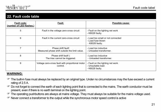
Fault code tabel
Fault code: (number of LED flashes.)
Fault: Possible cause:
5 Fault in the voltage zero-cross circuit - Fault on the lighting net work - K8028 faulty.
6 Fault in the current zero-cross circuit - Load too small or not connected - Load fuse blown - K8028 faulty.
7 Phase shift fault! Measured phase shift outside the limit value.
- Load too inductive - Unloaded transformer.
8 Phase shift fault! ( The triac cannot be triggered.
- Load too inductive - Unloaded transformer.
9 Voltage zero-cross fault with proportional motor control.
- Fault on the lighting net work. - Unsuitable load. - K8028 faulty.
22. Fault code table
WARNING:
The built-in fuse must always be replaced by an original type. Under no circumstances may the fuse exceed a current rating of 2.5 A.
Do not forget to connect the earth of each lighting point that is connected to the mains. The earth conductor must be present, even if there is no earth terminal on the lighting point.
The operating pushbuttons are always at mains voltage. They must always be suitable for the mains voltage used. Never connect a transformer to the output while the synchronous motor speed control is active
H8028IP'2-rev3.pubpage 21
Monday, August 27, 2012 10:04
22
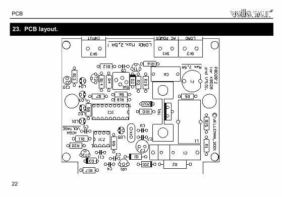
23. PCB layout.
PCB
H8028IP'2-rev3.pubpage 22
Monday, August 27, 2012 10:04
23
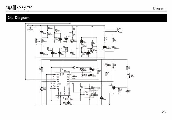
24. Diagram
Diagram
H8028IP'2-rev3.pubpage 23
Monday, August 27, 2012 10:04
5 4 1 0 3 2 9 2 9 1 2 7 3
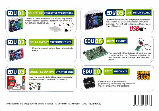
Learn how to connect your computer with the outside world, master the USB communication with tutorial examples. Play with LED indicators and learn how to drive LCDisplays.
This board with different signals will teach you how to use an oscilloscope. Optimized instructions for use of our HPS140 oscilloscope. YouTube demo movies.
Fun solar powered projects. Learn all about solar energy.
EXPERIMENT KIT SOLAR ENERGY EDUKIT SCOPE
TUTOR BOARD USB
Learn how to solder, build different exciting projects. Includes spare components and demo boards.
STARTER BOX SOLDER EDUCATIVE
The EDU01 basic experiment kit is the first step into the world of modern electronics. Build your own circuits in a fun, safe and educative way.
EDUCATIVE STARTERBOX SOLDERLESS
03
02
01
06
05
Enter the world of microcontroller programming, easy step by step instructions. Includes programmer and test board.
TUTOR KIT PICTM 10
Modifications and typographical errors reserved - © Velleman nv. H8028IP - 2012 - ED2 (rev.3)
H8028IP'2-rev3.pubpage 24
Monday, August 27, 2012 10:04


![journal - Springer · cytokines involved in asthma pathophysiology, ... [2,6,12,13]), illustrated in a schematic diagram ... Mukherjee et al. World Allergy Organization Journal 2014,](https://img.pdfslide.us/doc/110x75/5ae9c6b97f8b9a6d4f91308b/journal-springer-involved-in-asthma-pathophysiology-261213-illustrated.jpg)