Embed Size (px)
Citation preview
IL600SECTION EREV. 25 - 1/2002
Tek-DIGICARE®
NC205 Nurse Call System
UL® Listed 1069
INSTALLATION INSTRUCTIONSAND SERVICE MANUAL
APPLICATION: The NC205 Tek-DIGICARE® Nurse Call System is amicrocontroller based system consisting of central equipmentcabinet(s) along with patient/duty/staff/emergency/code/presencestations, dome/zone lights, and master stations.
The NC205 Series is designed for use in individual hospital wards,nursing homes, and congregate living centers.
Copyright © TekTone Sound & Signal Mfg., Inc. All Rights Reserved.
Alpha Communications®
42 Central DriveFarmingdale, NY 11735-1202Phone: (631) 777-5500Fax: (631) 777-5599
Website:www.alpha-comm.com
Email:[email protected]
TOLL-FREE Technical #:1-800-666-4800
Copyright © TekTone Sound & Signal Mfg., Inc. All Rights Reserved.ii • IL600 NC205 Tek-DIGICARE® Manual
Operation, Installation and Service ManualCopyright © 2002 TekTone® Sound & Signal Mfg., Inc., All rights reserved.
No part of this publication may be copied without the express written permission of TekTone® Sound & Signal Mfg., Inc. Thecontent of this manual is furnished for informational use only, is subject to change without notice, and should not beconstrued as a commitment by TekTone® Sound & Signal Mfg., Inc. TekTone® Sound & Signal Mfg., Inc. assumes noresponsibility or liability for any errors or inaccuracies that may appear in this documentation.
TekTone, the TekTone logo, Tek-Call, Tek-Care, Tek-Check-In, Tek-Com, Tek-Digicare, Tek-Door, Tek-Entry III, Tek-Guard, Tek-Micro, Tek-Micro II, Tek-MMARS II, TekNIOS, TekNIOS II, Tek-Paging, Tek-Phone, Tek-Safe, Tek-Select II,Tek-Sentry, Tek-Sound, Tek-Status, Tek-Trio and Tek-View are either registered trademarks or trademarks of TekTone®
Sound & Signal Mfg., Inc. in the United States and/or other countries. All other trademarks are the property of theirrespective owners.

Copyright © TekTone Sound & Signal Mfg., Inc. All Rights Reserved. IL600 NC205 Tek-DIGICARE® Manual • iii
TABLE OF CONTENTS
1.0 SYSTEM INTRODUCTION...................................................................................................... 1A Word About Electrostatic Discharge.............................................................................................................................. 1
2.0 INSTALLATION PROCEDURE................................................................................................32.1 EQUIPMENT SUMMARIES......................................................................................................................................... 3
NC260B Central EquipmentNC262A Central Equipment ExpanderPK261A Dome Light Power SupplyNC250 Master StationNC230 Master StationNC255 - 50 Station Master ExpanderPM261A Selector CardIR250 Standard Staff StationIR251 Single/IR252 Dual Standard Patient StationsIR253 Standard Pull Cord Patient StationIR254 Enhanced Staff StationIR255 Single/IR256 Dual Enhanced Patient StationsIR257 Single/IR258 Dual Enhanced Patient StationsIR259 Enhanced Multipurpose StationIR019C Speaker/Microphone StationIR260A Duty StationLI381 Single/LI382 Dual Corridor Dome/Zone LightsLI383/LI387 Corridor Dome/Zone LightsLI388A Corridor Zone LightSF100C Visual StationSF101C Visual StationBA002K Battery KitSF337C Pull Cord Shower/Emergency StationSF340B Pull Cord Emergency StationSF341B Code Call StationSF250 Staff Presence StationCall Cords
2.2 EQUIPMENT LOCATION............................................................................................................................................. 5NC260B Central EquipmentNC262A Central Equipment ExpanderPK261A Dome Light Power SupplyPM261A Selector CardNC250/NC230 Master Stations and NC255 Master Station ExpanderIR Series StationsLI Series Corridor Dome/Zone LightsSF Series Peripheral StationsCall Cords/Pillow Speakers
2.3 WIRING INSTALLATION............................................................................................................................................. 6NC260B Central Equipment and NC262A Central Equipment ExpanderPK261A Dome Light Power SupplyNC250/NC230 Master StationIR Series StationsLI Series Corridor Dome/Zone LightsSF Series Peripheral Stations
Copyright © TekTone Sound & Signal Mfg., Inc. All Rights Reserved.iv • IL600 NC205 Tek-DIGICARE® Manual
2.4 HOUSING INSTALLATION................................................................................................................................ 7NC260B Central Equipment and NC262A Central Equipment ExpanderPK261A Dome Light Power SupplyNC250/NC230 Master Stations and NC255 Master Station ExpanderIR Series StationsLI Series Corridor Dome/Zone LightsSF Series Peripheral Stations
2.5 WIRE CHECK-OUT........................................................................................................................................................ 8
2.6 WIRE CONNECTION..................................................................................................................................................... 8NC260B Central EquipmentNC262A Central Equipment ExpanderPK261A Dome Light Power SupplyNC250/NC230 Master StationsNC255 Master Station ExpandersIR Series StationsLI Series Corridor Dome/Zone LightsSF Series Peripheral Stations
2.7 VOLUME SETTINGS & ADJUSTMENTS.................................................................................................................. 10PM261A Selector CardsNC250/NC230 Master StationIR254-IR259 Enhanced Patient StationsIR260A Duty StationLI388A Corridor Zone Light
2.8 CONNECTIONS CHECK-OUT...................................................................................................................................... 11
2.9 NC205 INSTALLATION AND POWER-UP GUIDELINES........................................................................................11
3.0 SYSTEM EQUIPMENT DESCRIPTIONS................................................................................ 173.1 NC250/NC230 MASTER STATION..............................................................................................................................17
Function ButtonsNumerical KeysAlpha KeysStation Selector ButtonsPower ON LEDFault LEDPriority LED’S - GREEN, AMBER, and REDDIP SwitchHandsetHook SwitchVolume ControlSpeakerMicrophoneTray
3.2 NC255 MASTER EXPANDER.......................................................................................................................................19Station Selector ButtonsDIP Switch
3.3 MASTER STATION & EXPANDER DISPLAYS........................................................................................................ 19Call LocationFire CallsCode CallsEmergency/Bath/Priority/Cord Out CallsPersonal Attention and Routine CallsSystem Fault Indications
Copyright © TekTone Sound & Signal Mfg., Inc. All Rights Reserved. IL600 NC205 Tek-DIGICARE® Manual • v
3.4 PATIENT STATIONS............................................................................................................................................. 203.4-1 IR251/IR252 Standard Stations
Reset Button/In-Use LEDCall-Placed LEDCall Cord Receptacle
3.4-2 IR255-IR258 Enhanced StationsReset Button/In-Use LEDCall-Placed LEDCall Cord Receptacle
3.5 IR250 STANDARD/IR254 ENHANCED STAFF AND IR260A DUTY STATIONS...............................................21Reset Button/In-Use LEDCall Button/Call-Placed LEDIR260A Duty Station Special Features
3.6 IR253 STANDARD PULL CORD PATIENT STATION............................................................................................. 21Reset Button/In-Use LEDCall-Placed LEDPull Cord
3.7 IR259 ENHANCED MULTIPURPOSE STATION....................................................................................................... 22
3.8 SF100C VISUAL STATION............................................................................................................................................22Call-Placed LEDCall Cord ReceptacleCancel Button
3.9 SF101C VISUAL STATION............................................................................................................................................22Call-Placed LED/ Push buttonCancel Button
3.10 SF250 STAFF PRESENCE STATION........................................................................................................................... 23Staff Registration ButtonStaff Registration LED
3.11 SF337C/SF340B PULL CORD SHOWER/EMERGENCY STATION.........................................................................23Emergency Pull Down LeverCall-Placed LED
3.12 SF341B CODE CALL STATION...................................................................................................................................23Call/Reset LeverCall-Placed LED
3.13 LI SERIES CORRIDOR DOME/ZONE LIGHTS.......................................................................................................... 24Dome LightsZone Lights

Copyright © TekTone Sound & Signal Mfg., Inc. All Rights Reserved.vi • IL600 NC205 Tek-DIGICARE® Manual
4.0 OPERATIONAL PROCEDURES.............................................................................................. 254.1 MASTER STATION and EXPANDERS............................................................................................................... 25
4.1-1 CallingA. To answer a callB. To place a callC. To cancel a callD. To upgrade calls in progress
4.1-2 Staff ServiceA. To request staff serviceB. To cancel a staff service request or staff presenceC. To view staff status
4.1-3 PagingA. To page a specific zoneB. To page master preset zonesC. To page all stations on the system (ALL CALL)D. To page a staff memberE. To discontinue paging
4.1-4 Follower FunctionsA. To follow a staff memberB. To follow to a specific roomC. To discontinue the follower function
4.1-5 Station FunctionsA. To view a station’s zone assignments and statusB. To view and/or change stations in privacy modeC. To change the priority status of a stationD. To view the priority status of stations
4.1-6 Master FunctionsA. To enable room monitoringB. To view the master’s zone assignments and status
4.2 IR SERIES STATIONS.................................................................................................................................................... 274.2-1 IR251/IR252 Standard and IR255/IR256 Enhanced Patient Stations
A. To place a callB. To cancel a call
4.2-2 IR257/IR258 Enhanced Patient StationsA. To place a callB. To control the televisionC. To cancel a call
4.2-3 IR250 Standard and IR254 Enhanced Staff StationsA. To place a callB. To cancel a call
4.2-4 IR253 Standard Pull Cord StationA. To place a callB. To cancel a call
4.2-5 IR259 Enhanced Multipurpose StationA. To place a callB. To cancel a call
4.2-6 IR260A Duty StationA. To place a callB. To adjust the announcement volumeC. To cancel a call
4.3 SF SERIES PERIPHERAL STATIONS..........................................................................................................................274.3-1 SF100C Visual Station
A. To place a callB. To cancel a call

Copyright © TekTone Sound & Signal Mfg., Inc. All Rights Reserved. IL600 NC205 Tek-DIGICARE® Manual • vii
4.3-2 SF101C Visual StationA. To place a callB. To cancel a call
4.3-3 SF250 Staff Presence StationA. To register staff presenceB. To clear staff presenceC. To clear a staff request at a station
4.3-4 SF337C/SF340B Pull Cord Shower/Emergency StationA. To place a callB. To cancel a call
4.3-5 SF341B Code Call StationA. To place a callB. To cancel a call
5.0 SYSTEM CONFIGURATION/PROGRAMMING......................................................................295.1 MASTER STATIONS..................................................................................................................................................... 29
5.1-1 Entering the Programming ModeA. To select zone presetsB. To program master zonesC. To program master statusD. To view station fault list
5.1-2 Exiting the Programming Mode
5.2 PATIENT STATIONS..................................................................................................................................................... 305.2-1 Entering the Programming Mode
A. To assign zonesB. To program station statusC. To program a selector key for master-to-master communication
5.2-2 Exiting the Programming Mode
5.3 MASTER KEY PROGRAMMING/CONFIGURATION............................................................................................. 315.3-1 Entering the Programming Mode
A. To reset a master station to default values (erase flash memory)B. To add an expansion keypadC. To make a master “non-square”D. To custom configure a specific selector buttonE. To set the system time
5.3-2 Exiting the Programming Mode
5.4 EQUIPMENT RESET PROCEDURES.......................................................................................................................... 325.4-1 Central Equipment
A. To reset the central equipmentB. To reset the flash memoryC. To disable system programming from masters (programming lock)
5.4-2 Master StationsA. To reset a masterB. To erase flash memory
5.5 EXPANDING/UPGRADING THE SYSTEM................................................................................................................ 325.5-1 Adding Central Equipment Expander5.5-2 Adding Battery Backup5.5-3 Adding Master Stations5.5-4 Adding Master Expanders5.5-5 Adding Remote Stations5.5-6 Adding Peripheral Devices

Copyright © TekTone Sound & Signal Mfg., Inc. All Rights Reserved.viii • IL600 NC205 Tek-DIGICARE® Manual
5.6 VIEWING SYSTEM INFORMATION.......................................................................................................................... 335.6-1 Status Display Pages
A. Privacy displayB. Priority displayC. Staff display
5.6-2 FaultsA. Master station faultB. Code circuit faultC. Station fault
6.0 SYSTEM MAINTENANCE INSTRUCTIONS...........................................................................356.1 NC260B CENTRAL EQUIPMENT and NC262A CENTRAL EQUIPMENT EXPANDER ............................... 35
6.2 PK261A DOME LIGHT POWER SUPPLY....................................................................................................................35
6.3 NC250/NC230 MASTER STATIONS and NC255 MASTER STATION EXPANDER........................................... 356.3-1 Defective Handset/Cord Replacement6.3-2 8 PIN Modular Cord
6.4 IR SERIES STATIONS.................................................................................................................................................... 356.4-1 Defective Pillow Speaker Replacement6.4-2 Defective Call Cord Replacement
6.5 SF SERIES STATIONS................................................................................................................................................... 35
6.6 LI SERIES DOME/ZONE LIGHTS................................................................................................................................ 356.6-1 Defective Lamp Replacement
6.7 REPLACEMENTS PARTS............................................................................................................................................. 36
7.0 TEST INSTRUCTIONS............................................................................................................. 377.1 SYSTEM INSPECTION.................................................................................................................................................. 37
7.1-1 Basic Wiring Check7.1-2 Test Setup7.1-3 Viewing System Faults
7.2 CENTRAL EQUIPMENT AND EXPANDERS............................................................................................................ 377.2-1 NC260B Central Equipment7.2-2 NC262A Central Equipment Expander7.2-3 PK261A Dome Light Power Supply7.2-4 PM261A Selector Card
7.3 MASTER STATIONS AND EXPANDERS..................................................................................................................387.3-1 Basic Communications7.3-2 Staff Functions7.3-3 Paging Functions7.3-4 Follower Functions7.3-5 Priority Upgrade7.3-6 Privacy Functions
7.4 REMOTE STATIONS..................................................................................................................................................... 41
7.5 SF SERIES PERIPHERAL DEVICES............................................................................................................................ 42
7.6 LI SERIES PERIPHERAL DEVICES.............................................................................................................................. 43

Copyright © TekTone Sound & Signal Mfg., Inc. All Rights Reserved. IL600 NC205 Tek-DIGICARE® Manual • ix
APPENDIX
Appendix 1.0 ...................................................................................................................................................NC260B Communications Mode
1.1 General ................................................................................................................................ 441.2 Local Operation .................................................................................................................... 441.3 Remote Operation ................................................................................................................. 441.4 Communication Software ...................................................................................................... 45
Appendix 2.0 System Operation2.1 General .................................................................................................................................. 462.2 Error Codes and Messages .................................................................................................. 48
WIRING DIAGRAMSNL# Description Reference Section #
NL205-A NC205 Block Wiring Diagram w/Enhanced Stations and Dome LightConduit Runs ..................................................................................................................... 2.3, 2.6
NL205-B NC205 Block Wiring Diagram w/Standard Stations and Dome LightConduit Runs ..................................................................................................................... 2.3, 2.6
NL205-C NC205 Block Wiring Diagram w/Enhanced Stations and Station Conduit Runs ................ 2.3, 2.6NL205-D NC205 Block Wiring Diagram w/Standard Stations and Station Conduit Runs ................. 2.3, 2.6NL205-E NC260B Central Equipment Wiring ....................................................................................... 2.6NL205-F NC262A Central Equipment Expansion Wiring ..................................................................... 2.6NL205-G NC250/NC230 Master Stations & NC255 Master Station Expander ...................................... 2.6NL205-H Maximum Wiring Distances and Standard Wire Colors ...............................................2.2, 2.3, 2.5, 2.6NL205-H-1 Maximum Wiring Distances and Cable Configuration ................................................. 2.2, 2.3, 2.5, 2.6NL205-H-2 Maximum Wiring Distances and Central Equipment Configuration ............................. 2.2, 2.3, 2.5, 2.6NL205-I IR250-IR253 Station Wiring (includes SF Series and LI Series Peripherals) .......................... 2.6NL205-J IR250-IR253 Station Wiring (reduced wiring scheme with Emergency Peripheral) ................ 2.6NL205-K IR254-IR256 Enhanced Station Wiring (includes SF and LI Peripherals) ............................... 2.6NL205-L IR254-IR256 Enhanced Station Wiring in Multiples (includes SF and LI Peripherals) .......... 2.6NL205-M IR257 and IR258 Enhanced Station Wiring ............................................................................ 2.6NL205-N IR260A Duty Station and LI388A Zone Light Wiring ........................................................... 2.6NL205-O IR259 Enhanced Station Wiring ......................................................................................... 2.6, 3.7NL205-P Stand Alone use of SF Series Peripherals (includes fire or smoke contacts) .................... 2.6, 3.10NL205-P1 Visual Station with peripherals (includes emergency station and smoke contacts) ........ 2.6, 3.8, 3.9NL205-Q NC260B/NC262A 120 VAC Connection Diagram................................................................... 2.6NL205-R PK261A Wiring Diagram ....................................................................................................... 2.6NL205-S Battery Kit Installation .......................................................................................................... 2.6

Copyright © TekTone Sound & Signal Mfg., Inc. All Rights Reserved.x • IL600 NC205 Tek-DIGICARE® Manual
FIGURESFig. # Description Page #
1 IH352 Ring and IH353 Housing Installation ........................................................................... 72 IH357 Ring and IH358 Housing Installation ........................................................................... 73 Master Station Cable Assembly Wiring ................................................................................. 94 PM261A Selector Card ........................................................................................................... 95 Master Station Controls .........................................................................................................106 Code Fault Jumper ................................................................................................................. 117 IR260A Duty Station ..............................................................................................................118 NC250 Master ........................................................................................................................ 179 NC250/NC230 Master DIP Switch Controls ........................................................................... 1810 NC255 Master Expander .........................................................................................................1911 IR251/IR252 Standard and IR255/IR256/IR257/IR258 Enhanced Patient Stations .................. 2012 IR250 Standard/IR254 Enhanced Staff and IR260A Duty Stations......................................... 2113 IR253 Standard Pull Cord Patient Station ............................................................................... 2114 IR259 Enhanced Multipurpose Station .................................................................................. 2215 SF100C Visual Station ............................................................................................................ 2216 SF101C Visual Station ............................................................................................................ 2217 SF250 Staff Presence Station ..................................................................................................2318 SF337C/SF340B Pull Cord Shower/Emergency Station .......................................................... 2319 SF341B Code Call Station ....................................................................................................... 2320 LI381/LI382/LI383 Corridor Dome/Zone Lights ...................................................................... 2421 LI387/LI388A Corridor Dome/Zone Lights ............................................................................. 2422 NC250/NC230 Programming Inserts ....................................................................................... 2923 NC250/NC230 Master DIP Switch Controls ........................................................................... 3124 NC260B Null Modem Cable ....................................................................................................4425 NC260B Communications Mode Help Screen ........................................................................ 4626 NC260B Dip Switch Settings ..................................................................................................47

IL600 NC205 Tek-DIGICARE® Manual • 1Copyright © TekTone Sound & Signal Mfg., Inc. All Rights Reserved.
The NC205 Nurse Call System is a supervised, microcontrollerbased system that provides a complete range of two-wayaudio and visual signaling for staff-to-patient and staff-to-staff communications.
The NC250/NC230 Master Stations and NC255 MasterExpander make up the control console where patient calls areregistered and displayed. The control consoles providefacilities for:
• locating and dispatching staff personnel• managing patient priority and privacy• monitoring all emergency situations• performing system configurations• monitoring code, communication, station,
and central equipment faults.
1.0 SYSTEM INTRODUCTION
The NC205 Nurse Call System is complemented by a widerange of bedside stations and peripherals:
• duty and staff stations• single and dual patient stations• dome and zone corridor lights• code, emergency, bath, and
staff presence peripheralsThe features of the master stations, bedside stations, andperipherals are discussed in greater detail in Section 3.0-System Equipment Description.
Simplified wiring and plug-in design provide ease ofinstallation in new and/or existing facilities. Modular circuitryand interchangeable room stations permit the system to beeasily upgraded and expanded at anytime.
A WORD ABOUT ELECTROSTATIC DISCHARGE
What Is It? Static electricity is a result of triboelectric charging of two dissimilar nonconductive materials rubbed together, like rubbing yourfeet on a carpet on a cold winter day, or in a dry climate. The resulting charge is detected when you reach out to touch a doorknob or someother metallic object. The resulting discharge may be only startling, or in severe cases it may even be painful. The actual electrical chargeis dependent on the materials rubbed together, humidity, rate of separation and other factors.
What Can It Do? While this effect may be disturbing to humans, the effect on electronic equipment is often more serious, ranging fromdisrupting the operation to actual damage of the components. These effects result from the high voltages that may be developed. The simpleact of walking across a carpet may develop as much as 30,000 volts; changing a bed sheet may create a charge of 100,000 volts or more. Suchvoltages readily cause arcing (the spark you see in the dark when you grab the doorknob, after walking across the carpet, etc.). The arcingis evidence of a discharge path. Due to the high voltage involved, the discharge current can jump to any nearby metallic object. If the dischargeis to or through an electronic device, such as the nurse call system, the operation of the device may be affected. If the discharge current passesthrough internal components, these components may be damaged or their operation degraded.
What Can We Do About It? The manufacturer of the nurse call equipment has already taken steps to protect the equipment from electrostaticdischarge (ESD) effects. However, since the cause of the problem is not in the equipment, but in the environment, further measures are requiredof the installer and the user to achieve complete protection.
What The Installer Can Do: In humid climates or in places where the relative humidity is kept at 65% or greater, there will likely befew problems with ESD. Where problems may occur, the following measures can be taken.1. Ground all exposed metal surfaces, such as patient station panels, etc. Grounding should be to a #14 or larger conductor.2. Install nurse call system wiring in metal conduit. This conduit may also be used to ground panels. The conduit must be electrically
continuous and be grounded.3. Use shielded wire in cable for nurse call system station- to-station wiring. The use of open conductors invites inductive coupling of
discharge currents which can cause the same problems as direct discharge currents.4. Ground your body before handling system components. This can be done using a wrist strap, or simply by contacting a grounded surface.
Use caution to avoid hazardous voltages while grounded.
What The User Can Do: The most common generation of ESD in hospitals is due to changing linen on hospital beds while the patientcall cord or pillow speaker is still connected to the nurse call system. The following precautions will help.1. Remove the call cord or pillow speaker from the bed before changing. It will be necessary for the nursing staff to discharge themselves
by contacting a grounded metal object before placing the call cord or pillow speaker back on the bed; otherwise, a spark will jump tothe nurse call equipment, causing the very damage they are trying to avoid. (To avoid a shock while discharging static electricity onthe body, hold a metal object, such as a key, and use that object to contact the grounded surface.)
2. Ground the bed and use antistatic mattress covers in contact with the bed frame. For safety, it may be desirable to make the groundconnection through a 1 megohm resistor. Nursing staff must be trained to disconnect and reconnect the ground whenever beds haveto be moved.
3. Use grounded appliances and equipment near nurse call systems. The use of approved electrical equipment will usually take care ofthis.
This information is provided to make you aware of ESD problems so that precautions may be taken to avoid damage and disruption of systemoperation.

2 • IL600 NC205 Tek-DIGICARE® Manual Copyright © TekTone Sound & Signal Mfg., Inc. All Rights Reserved.

IL600 NC205 Tek-DIGICARE® Manual • 3Copyright © TekTone Sound & Signal Mfg., Inc. All Rights Reserved.
Read the following instructions concerning systemequipment and determine installation methods beforeproceeding. Also review installation and power-upguidelines, section 2.9, when equipment has been received.A. Determine equipment locations.B. Install wiring.C. Install housings.D. Check wires.E. Connect equipment.F. Check connections.G. Test system.H. Configure system.I. Train system operators.
2.1 EQUIPMENT SUMMARIES
NC260B Central EquipmentThe NC260B provides microcontroller, signaling, and powercircuitry (except in applications requiring the PK261A) tooperate the NC205 Nurse Call System. The central equipmentmay interface with up to four NC250/NC230 Master Stationsand their NC255 Master Expanders, and one NC262A CentralEquipment Expander. The central equipment consists ofmicrocontroller, memory, interface, and power supply circuits.All outputs are protected by self-resetting current limitingcircuitry. All equipment is completely contained in a hingedsurface mount cabinet. A recommended backup battery kit isavailable.
NC262A Central Equipment ExpanderThe NC262A provides the additional circuitry necessary tointerface with the NC260B Central Equipment and twoadditional PM261A Selector Cards. It also includes anadditional power supply. This enables the system to beexpanded to 128 remote stations.
NOTE: A 128 remote station (maximum) system wouldrequire:
1 - NC260B with 2 - PM261A’s1 - NC262A with 2 - PM261A’s
PK261A Dome Light Power SupplyThe PK261A Dome Light Power Supply provides power fordome lights connected to enhanced patients stations (IR254-259). Connections to dome light field wiring are provided viaa plug-on connector.
NC250 Master StationThe NC250 utilizes digital technology to providecommunications, fault monitoring, and programming for theNC205 Nurse Call System. The master station consists of ahandset, volume control, speaker, microphone, 8 color-codedfunction buttons, 50 individual room selector buttons, andLED’s for call priority, power, and fault. All LED’s and buttonsare on a spill-proof membrane switch assembly.
NC230 Master StationThe NC230 has the same functionality as the NC250 butprovides 30 individual room selector buttons with LED’s.
NC255 - 50 Station Master ExpanderThe NC255 provides the additional circuitry and buttons toexpand the capacity of a master station by 50 rooms. CallLED’s and selector buttons are on a spill-proof membraneswitch assembly.
PM261A Selector CardThe PM261A provides connection points for up to 32 stations.Integrated digital and analog technology provide for reliablecommunications between system components. Each NC260B/NC262A is capable of supporting two PM261A Selector Cardsto provide access for up to 64 IR Series Remote Stations.
IR250 Standard Staff StationThe IR250 provides reliable two-way, hands-freecommunication between the nurse master station and anylocation where staff members may need to originate calls orwhere cord sets are not required. It may also function as apush button patient station. The station contains acombination yellow “CALL-PLACED” indicator and “CALL”button, a combination red “IN-USE” indicator and “RESET”button, and a speaker/microphone. The IR250 is mounted onan attractive flame retardant type ABS plastic faceplate. TheIR250 operates with single and dual lamp dome lights (LI381/LI382), and has inputs for “BATH/EMERGENCY” and “FIRE.”
IR251 Single/IR252 Dual Standard Patient StationsThe IR251/IR252 stations include yellow “CALL-PLACED”indicator(s), patient call cord receptacle(s), a combinationred “IN-USE” indicator and “RESET” button, and a speaker/microphone. The stations use 1/4" phone jack(s) and aremounted on attractive flame retardant type ABS plasticfaceplates. Both provide outputs for single/dual light domelights (LI381/LI382) and two peripheral devices(“EMERGENCY” and “FIRE”).
IR253 Standard Pull Cord Patient StationThe IR253 has all the same functions as the IR251/IR252Stations, but provides a patient pull cord instead of call cordjack. The IR253 consists of a yellow “CALL-PLACED”indicator, a combination red “IN-USE” indicator and “RESET”button, and a speaker/microphone. The IR253 is mounted onan attractive flame retardant type ABS plastic faceplate, andprovides outputs for single and dual lamp dome lights (LI381/LI382) and two peripheral devices (“EMERGENCY” and“FIRE”).
2.0 INSTALLATION PROCEDURE

4 • IL600 NC205 Tek-DIGICARE® Manual Copyright © TekTone Sound & Signal Mfg., Inc. All Rights Reserved.
IR254 Enhanced Staff StationThe IR254 provides reliable two-way, hands-freecommunication between the nurse master station and anylocation where staff members may need to originate calls orwhere cord sets are not required. It may also function as apush button patient station. The station has a combinationyellow “CALL-PLACED” indicator and “CALL” button, acombination red “IN-USE” indicator and “RESET” button,and a speaker/microphone. The IR254 is mounted on anattractive flame retardant type ABS plastic faceplate. TheIR254 includes supervision circuitry for code station andassociated wiring, additional outputs for a three lamp (LI383)or four lamp dome light (LI387), and additional inputs formultiple peripheral devices. Power and select wires aresupervised by central equipment.
IR255 Single/IR256 Dual Enhanced Patient StationsThe IR255/IR256 have the same basic functionality as theIR251/IR252, but include microcontroller and supervisioncircuitry for code station and associated wiring, to interfacewith multiple peripheral devices. Both stations provideoutputs for three lamp (LI383) or four lamp dome lights (LI387).Power and select wires are supervised by central equipment.
IR257 Single/IR258 Dual Enhanced Patient StationsThe IR257/IR258 have all the same functions as the IR255/IR256 but use 8-pin modular jack receptacle(s) to interfacewith TekTone®’s SF301P Pillow Speakers or SF311/SF312Series Call Cords.
IR259 Enhanced Multipurpose StationThe IR259 is patterned after the IR254, but has no usercontrols. The IR259 is mounted on an attractive flameretardant type ABS plastic blank faceplate. It providesconnections for external call and reset buttons, “CALL-PLACED” and “IN-USE” indicators, and an external speaker/microphone.
IR019C Speaker/Microphone StationThe IR019C provides audio communication capabilities whenused in conjunction with the IR259 Enhanced MultipurposeStation and features a durable stainless steel faceplate.
IR260A Duty StationThe IR260A has all of the features and functions of the IR250,but includes an “EMERGENCY” LED indicator andmicrocontroller circuitry to display call information fromspecific zones on associated zone lights (see descriptionsbelow). The IR260A also provides remote tone annunciationof calls placed from any one or all of eight programmablezones. Note: NC205 System is limited to 8 duty devices if thePK261A Dome Lamp Power Supply is not used. These dutydevices may be LI388A or IR260A with dome lamps, in anycombination, not to exceed 8.
LI381 Single/LI382 Dual Corridor Dome/Zone LightsThe LI381/LI382 provides visual indication of calls originatingfrom patient, staff, bath, and stand alone stations. Low prioritycalls are indicated by a white lamp. The LI382 provides anadditional lamp (red) for indication of higher priority calls.The LI381/LI382 may also be used as zone lights when usedwith an IR260A Duty Station but will only display those callsassociated with one or two lamps.
LI383/LI387 Corridor Dome/Zone LightsThe LI383/LI387 provides visual indication of calls originatingfrom patient, staff, and duty stations. The LI387 also providesvisual indication of calls originating from code call stations.The LI383 consists of three incandescent lamps (red, green,and white) covered by a single polystyrene lens. The LI387consists of four incandescent lamps covered by translucentpolycarbonate (red, green, and blue) and polystyrene (white)lenses mounted on an attractive ABS plastic base. Call priorityand staff presence are indicated by various flash rates appliedto the appropriate lamp(s). The LI387 functions as a zonelight when used with the IR260A Duty Station. The LI383 willalso function as a zone light when used with the IR260ADuty Station but will only display calls that are associatedwith one, two, or three lamps.
LI388A Corridor Zone LightThe LI388A is identical in appearance to the LI387, butcontains microcontroller and support circuitry to display callpriority indications from any or all of eight programmablezones. The LI388A serves the same functions as an LI387that is connected to an IR260A. Note: NC205 System is limitedto 8 duty devices if the PK261A Dome Lamp Power Supply isnot used. These duty devices may be LI388A or IR260A withdome lamps, in any combination, not to exceed 8.
SF100C Visual StationThe SF100C is used to operate “ROUTINE” signals. Thestation consists of an attractive flame retardant type ABSplastic faceplate, a yellow “CALL-PLACED” indicator, a“CANCEL” button, and a patient call cord receptacle (1/4"phone jack). The SF100C is a stand-alone device.
SF101C Visual StationThe SF101C is used to operate “ROUTINE” signals. Thestation consists of an attractive flame retardant type ABSplastic faceplate, an amber “CALL-PLACED” indicator/pushbutton, and a “CANCEL” push button. The SF101C is a stand-alone device.
BA002K Battery KitThe BA002K Kit provides battery backup for NC260B CE orNC262A CEE. The kit includes two BA001 Batteries(12 VDC, 2.0 AH) and connection harness.

IL600 NC205 Tek-DIGICARE® Manual • 5Copyright © TekTone Sound & Signal Mfg., Inc. All Rights Reserved.
SF337C Pull Cord Shower/Emergency StationThe SF337C is used to operate “BATH/EMERGENCY”signals. The station consists of an attractive flame retardanttype ABS plastic faceplate, a red pull down lever, 7' nyloncord with pendant, mounting screws, connector, a red “CALL-PLACED” indicator, and electronic circuitry mounted to theback of the faceplate. The SF337C is waterproof, whenmounted correctly, and is provided with a white rubber gasket,mounting screws with “O” rings, and a circuit board withreed switches.
SF340B Pull Cord Emergency StationThe SF340B is used to operate “BATH/EMERGENCY”signals. The station consists of an attractive flame retardanttype ABS plastic faceplate, a red pull down lever, 7' nyloncord with pendant, mounting screws, connector, a red “CALL-PLACED” indicator, and electronic circuitry with a DPDTswitch mounted to the back of the faceplate.
SF341B Code Call StationThe SF341B is used to initiate “CODE” signals and ismonitored for fault conditions by IR254-259 Enhanced PatientStations. The SF341B consists of an attractive flame retardanttype ABS plastic faceplate, a blue pull down lever, a 7' nyloncord with pendant, and mounting screws. A circuit boardwith a DPDT switch, connectors, a red “CALL-PLACED”indicator, and electronic circuitry is mounted to the back ofthe faceplate.
SF250 Staff Presence StationThe SF250 provides push button registration of staff membersat remote locations when used with IR254-IR259 EnhancedPatient Stations. The SF250 may also be used to transfer stafffollower features from one room to another. The station’scircuitry is mounted on an attractive flame retardant typeABS plastic faceplate and contains a push button and a greenLED indicator.
Call CordsFor use with IR251/IR252/IR255/IR256 and SF100C :SF301 - Push button with 7' cordSF301G - Geriatric push button call cordSF301/10 - Push button with 10' cordSF302 - Dual push button with 7' cordsSF302G - Geriatric dual push button call cordSF302/10 - Dual push button with 10' cords
For use with IR257/IR258 :SF301P Series - Pillow speakerSF311 - Push button cord w/modular jackSF311G - Geriatric/oxygen call cordSF312 - Dual push button cords w/modular
jackSF312G - Geriatric/oxygen dual call cords
2.2 EQUIPMENT LOCATION
Locate NC205 System equipment in accordance with thefollowing information. The installation of all systemequipment must meet the requirements of the NationalElectrical Code, ANSI/NFPA #70, current edition. Do notlocate or install NC205 System components in or near areasof high humidity, static electricity, radiation, or heat.
NOTE: Please observe the maximum wiring distance perNL205-H.
NC260B Central EquipmentThe central equipment should be located in an accessiblearea near a dedicated AC source, preferably central to theassociated master stations. For optimum operation, the centralequipment should be located in an area with an operatingtemperature of approximately 26°C with 70-80% relativehumidity. Equipment should be accessible to a good localearth ground using a minimum of #14 gauge wire. Locationshould have convenient cable runs to the master and patientstations. The central equipment may be wall mounted (surfaceor recessed). A battery backup kit is recommended and shouldbe located within the central equipment.
NC262A Central Equipment ExpanderThe central equipment expander should be located in anaccessible area near a dedicated AC source. For optimumoperation, the central equipment expander should be locatedin an area with an operating temperature of approximately26°C with 70-80% relative humidity. Equipment should bewithin 18 feet of the NC260B. The location should haveconvenient cable runs to the central equipment and patientstations. The central equipment expanders may be wallmounted (surface or recessed). A battery backup kit isrecommended and should be located within the NC262AExpander cabinet.
PK261A Dome Light Power SupplyThe dome light power supply should be located in anaccessible area near a dedicated AC source. For optimumoperation, the dome light power supply should be located inan area with an operating temperature of approximately 26°Cwith 70-80% relative humidity. Equipment should be accessibleto the NC260B. Location should have convenient cable runsto the central equipment and patient stations. The dome lightpower supply may be wall mounted (surface or recessed).
PM261A Selector CardThe selector cards are mounted inside the NC260B CentralEquipment and the NC262A Central Equipment Expander.

6 • IL600 NC205 Tek-DIGICARE® Manual Copyright © TekTone Sound & Signal Mfg., Inc. All Rights Reserved.
NC250/NC230 Master Stations and NC255 Master StationExpanderThe master stations and expanders should be located on adesk or countertop within easy reach of operating personnel.Each master station is provided with 7' of cable and an 8conductor modular connector. The expander(s) are providedwith 1.3' of cable and an 8 conductor modular connector forconnection to the masters. The master station(s) should belocated within easy reach of the modular wall plate (TekTone®
PL467) for cable termination. Locate the wall plate on a singlegang ring or box. The operating temperature range of 10°C -40°C should not be exceeded.
IR Series StationsThe patient stations should be located where convenient foroperation, most commonly at the head of the patient’s bed.The operating temperature range of 10°C - 40°C should notbe exceeded.
The IR250/IR254 Staff Stations should be located whereconvenient for operation in areas such as utility rooms, examrooms, kitchens, and wherever staff members may need tooriginate calls. The IR250/IR254 may also be used as patientstations in rooms where cord sets are not required.
The IR259 Enhanced Multipurpose Station should becentrally located in regard to the remotely mounted initiationdevices (switches, contact closures, loudspeakers, or othersignal-originating equipment) with which it is used. Nocontrols are provided.
The IR019C Speaker/Microphone Station should be locatedwhere audible in conjunction with the IR259. The IR019C isdesigned for use in high security areas, such as psychiatricwards. It is flush mounted, normally in the ceiling or out ofthe patient’s reach.
The IR260A Duty Station should be located where convenientfor operation in areas such as utility and exam rooms, orwhere a nurse may perform a function out of hearing or sightof the NC250/NC230 Master Station.
LI Series Corridor Dome/Zone LightsThe dome lights should be located in the corridor above orbeside the door of the associated room. The location shouldprovide unobstructed visibility of the corridor light in bothdirections. The zone lights should be located in the corridorarea nearest the nurses central monitoring station.
SF Series Peripheral StationsThe SF100C or SF101C Visual Station should be located whereconvenient for operation, most commonly at the head of thepatient’s bed. The operating temperature range of 10°C - 40°Cshould not be exceeded.
The SF250 Staff Presence Station should be located forconvenient operations, usually near the room entrance.
The emergency stations should be located where convenientfor operation in areas such as toilets, baths, or shower rooms.The code call stations should be located for convenientoperation in areas such as ICU/CCU, physical therapy rooms,and post-op recovery.
The SF337C Pull Cord Shower/Emergency Station may beused as a pull station or a pull cord station. To use as a pullcord station, thread nylon cord through hole provided in theguide tab on lower position of the faceplate and red pulldown lever. Secure with a double knot; then mount stationhigh enough for convenient operation by seated or pronepatients. When used as a pull station, locate where access isconvenient for both patients and nurses. The SF337C iswaterproof when properly installed.
The SF340B Emergency Station may be used as a pull stationor a pull cord station (as the SF337C). When used as a pullstation, locate where access is convenient for both patientsand nurses. Avoid areas where direct contact with water mayoccur.
The SF341B Code Call Station may also be used as a pullstation or pull cord station to initiate the highest level of callpriority.
Call Cords/Pillow SpeakersThe call cord/pillow speakers should be inserted intoassociated station jacks or receptacles. Call cords/pillowspeakers should not be installed in patient areas that areelectrically susceptible or in areas where flammable gases areused.
2.3 WIRING INSTALLATION
NC205 system wiring should not be run with any other buildingwiring. All dead-metal parts of the NC205 system must beconnected to a good local earth ground, and current carryingconductors must not be exposed. DO NOT RUN CONDUITOR WIRE TO BOTTOM KNOCKOUTS OF IR SERIESSTATION BOX - NO ACCESS IS AVAILABLE. DO NOT USEKNOCKOUTS ON TOP OF NC260B OR NC262A CASES.
Wiring conduit may be run from dome light to dome light,station to station, or a combination of the two, terminating atthe Central Equipment.
NOTE: Field wiring terminations should not be made withinNC260B or NC262A enclosures. TekTone® recommendsexternally located connections (e.g., mounted terminal/barrier strips, etc.) used in conjunction with system cableassemblies to terminate field wiring.

IL600 NC205 Tek-DIGICARE® Manual • 7Copyright © TekTone Sound & Signal Mfg., Inc. All Rights Reserved.
SF Series Peripheral StationsRun #22 stranded to patient station, or if stand alone run #18stranded to central equipment.
2.4 HOUSING INSTALLATION
NC260B Central Equipment and NC262A CentralEquipment ExpanderThe central equipment and expander are self-contained in ahinged door cabinet. The units may be wall mounted usinghardware provided.
PK261A Dome Light Power SupplyThe dome light power supply is self-contained in a hingeddoor cabinet. The unit may be wall mounted using hardwareprovided.
NC250/NC230 Master Stations and NC255 Master StationExpanderThe master stations and master station expanders aredesigned to be desk or wall mounted.
IR Series StationsInstall the back box TekTone® #IH353, (Steel City #H3BD orexact equivalent) with TekTone® #IH352 (Steel City #3GCplaster ring or exact equivalent), as shown in Figure 1 foreach station in system. Minimum dimensions of the back boxto be not less than 8.6" x 4.5" x 2.5". Minimum clearance fromlive parts on the station to dead metal parts to be not lessthan 1/2".
LI Series Corridor Dome/Zone LightsInstall the two gang back box (Steel City #H2BD or exactequivalent) with the two gang plaster ring (Steel City #2GCor exact equivalent), as shown in Figure 2 for each station insystem. Minimum dimensions of back box to be not less than2-3/4" x 2-3/4". Minimum clearance from live parts on thestation to dead metal parts to be not less than1/2". Minimum clearance from live parts on the station todead metal parts to be not less than 1/2".
TekTone® recommends running conduit from dome light todome light because of the reduced conduit lengths. Each runmust be limited to no more than 8 stations, with or withoutdome lights. Select conduit size to accommodate theappropriate cables. Run station wiring in accordance withthe following information and notes provided on the blockwiring diagrams NL205-A, NL205-B, NL205-C, and NL205-D.
NOTE: Please observe the maximum wiring distance perNL205-H.
NC260B Central Equipment and NC262A CentralEquipment ExpanderThe central equipment should use a dedicated, computer-grade power line (120 VAC, 60 Hz, 20 A - contact factory forother power options). This line should also be connected toan emergency power feed that conforms to UL® 1069Standards. Power supplies and all dead-metal parts of theNC205 System must be connected to the NC260B chassisground lug, which is in turn connected to a good local earthground. Recommended power devices include AC powersurge suppressors, line conditioners, and uninterruptablepower sources (UPS). All devices must be UL® Listed andrated for the appropriate load.
PK261A Dome Light Power SupplyThe dome light power supply should use a dedicated,computer grade power line (120 VAC, 60 Hz, 20 A - contactfactory for other power options). This line should also beconnected to an emergency power feed that conforms toUL® 1069 Standards. Power supplies and all dead-metal partsof the NC205 System must be connected to the PK261Achassis ground lug, which is in turn connected to the NC260Bchassis ground lug. Recommended power devices includeAC power surge suppressors, line conditioners, anduninterruptable power supplies (UPS). All devices must beUL® Listed and rated for the appropriate load.
NC250/NC230 Master StationRun 4 conductor #18 stranded shielded and 4 conductor #18stranded from supplied wallplate to central equipment. Eachmaster station must be home run to the central equipment.
IR Series StationsRun 1 twisted shielded pair #18 stranded common, plus 4conductors #18 stranded common, plus 1 conductor #22stranded selective per IR Series Station, to central equipment.(If enhanced stations are used with dome lamps add oneadditional #18 common, if standard stations are used withperipherals add an additional #18 for slow flash buss foremergency stations. Add additional #18 for fast flash bussfor smoke detectors or code switches.)
LI Series Corridor Dome/Zone LightsRun up to 7 conductor #18 stranded per light according totype and location.
FIG. 1: IH352 Ring and IH353 Housing Installation
FIG. 2: IH357 Ring and IH358 Housing Installation

8 • IL600 NC205 Tek-DIGICARE® Manual Copyright © TekTone Sound & Signal Mfg., Inc. All Rights Reserved.
SF Series Peripheral StationsInstall the back box TekTone® #IH358 (Steel City #52171 orexact equivalent) with TekTone® #IH357 (Steel City #52C14plaster ring or exact equivalent), as shown in Figure 2, foreach station in system. Minimum clearance from live parts onthe station to dead metal parts to be not less than 1/2". Toinsure a seal between the SF337C faceplate and wall, thegasket must be mounted between the faceplate and wall. Themounting screws with “O” Rings must be used to furtherinsure that there is a water-tight installation. Take care thathousing location will be such that the finished wall providesa flat, even surface (installation of the housing in the seamsof tile will require additional caulking between gasket andwall).
2.5 WIRE CHECK-OUT
A. Use an ohm meter or other continuity checking deviceto test for shorts or grounds. If shorts or grounds areencountered, find and correct the problem beforecontinuing. All shield drain wires must showcontinuity throughout the cable run.
B. Drains must be kept separate from all otherconductors and cannot be touching any part ofmetal conduits or boxes. Drains should be tapedback at the end of cable runs. All drains shouldreturn back to the central equipment (NC260B)and connect to a good earth ground. NOTE:Audio shields should be connected to adedicated earth ground with the system commonat one point. These shields should be continuousuntil the end of the run, where they will be tapedback and isolated. Any unused wires in thecommon control cables or in the selective linecables should be grounded at the centralequipment with their other ends left floating. Ifselective line cable has a shield, the shieldshould be grounded at the central equipmentas well.
C. Make sure the minimum number of conductors neededfor all of the equipment being used in the system areavailable. Make sure the maximum wiring distancesare not exceeded (see NL205-H).
2.6 WIRE CONNECTION
Make wire connections in accordance with the followinginformation and WIRING DIAGRAMS NL205-A thruNL205-S. All stations and central equipment are suppliedwith cable assemblies terminated by plug-in type connectorsfor easy wiring.
NOTE: Field wiring terminations should not be madewithin NC260B, NC262A enclosures. TekTone®recommends externally located connections (e.g.mounted terminal/barrier strips, etc.) used inconjunction with system cable assembles to terminatefield wiring.
NC260B Central EquipmentGround the central equipment chassis to a good earth ground.120 VAC must be provided to the central equipment. Do notapply power until all connections to equipment have beenchecked. If necessary, call the factory for other poweroptions. (Refer to NL205-E.)
NC262A Central Equipment ExpanderNC262A Central Equipment Expander use 25 pin (DB25) and2-pin headers to interconnect. 120 VAC must be provided tothe NC262A expander. (Refer to NL205-F.)
PK261A Dome Light Power SupplyGround the dome light power supply chassis ground lug tothe chassis ground lug of the NC260B. 120 VAC must beprovided to the dome light power supply. DO NOT applypower until all connections to equipment have been checked.If necessary, call the factory for other power options. (Referto NL205-R.)
NC250/NC230 Master StationsThe master station(s) cable assembly should be plugged intothe wall plate supplied with each master station. Run cablefrom the wall plate to the appropriate cable assembly at thecentral equipment. (See Figure 3 and NL205-G for details.)
NC255 Master Station ExpanderPlug cable provided into appropriate jack located in back of theNC250 or NC230 Master Stations. (Refer to NL205-G.)
IR Series StationsEach station is provided with cable assemblies terminated byplug-in type connectors. Connect field wiring according towiring diagrams.
(CAUTION: Static electricity can cause damage to thestations.)
LI Series Corridor Dome/Zone LightsConnect wires as shown in wiring diagrams.
SF Series Peripheral StationsPlug in connector/cable assembly supplied with each station.Connect wires as shown in wiring diagrams.

IL600 NC205 Tek-DIGICARE® Manual • 9Copyright © TekTone Sound & Signal Mfg., Inc. All Rights Reserved.
FIG. 3: Master Station Cable Assembly Wiring
FIG. 4: PM261A Selector Card
!Audio
VolumeControl
Wal l P la te (TekTone® Par t #PL467)
WHITE BLUE
BROWN ORANGE
YELLOW BLACK
GREEN RED
1
2
3
45
6
7
8
To Master #1
To Master #2
To Master #3
To Master #4
M A S T E R # 4
M A S T E R # 3
M A S T E R # 2
M A S T E R # 1
8 wires each
12345678
+18V
DC
CO
NTR
OL
INPO
WER
ON
CO
NTR
OL
OU
TD
IGIT
AL
AU
DIO
INFA
ULT
DIG
ITA
LA
UD
IOO
UT
SYST
EMG
RO
UN
D
4 - # 1 8 s h i e l d e d a n d 4 -#18 per mas te r s ta t i on .(See no te be low)
NC260B Central Equipment
*ALL
FIE
LDW
IRIN
GM
US
TB
ET
ER
MIN
AT
ED
OU
SID
EO
FS
YS
TE
ME
QU
IPM
EN
TE
NC
LOS
UR
ES
*
8 conductor Modular cable (7' cableprovided each Master Station) witheach Master Stat ion
Observe wire and pin NAMES when connecting equipment !!!
NC255MASTER EXPANDER
NOTE:Addressing NC255 Master Expanders incorrectlywill result in damage to units upon power application.Check Figure 9 for correct dipswitch settings.
Modular jacks
Expander IN Expander OUT
To otherExpanders
1
2
3
4
5
6
7
8
8
7
6
5
4
3
2
1
(1.3' cable providedwith each MasterExpander)
8 conductorModular cable
1=+18VDC2=CONTROL IN3=POWER ON4=CONTROL OUT5=DIGITAL AUDIO IN6=FAULT7=DIGITAL AUDIO OUT8=SYSTEM GROUND
Modular jacks
Master IN Expander OUT8
7
6
5
4
3
2
1
8
7
6
5
4
3
2
1
NC250/230MASTER STATION
Refer to NL205-G

10 • IL600 NC205 Tek-DIGICARE® Manual Copyright © TekTone Sound & Signal Mfg., Inc. All Rights Reserved.
CallToneVolume
MasterReceiveVolume
!
HandsetSensitivity
"
"
FIG. 5: Master Station Controls
2.7 VOLUME SETTINGS & ADJUSTMENTS
PM261A Selector CardsThe audio volume control is located on the selector card(PM261A) as shown in Figure 4. Turn control counter-clockwise to increase outgoing volume to patient stations.(The PM261A is located within the NC260B/NC262A.)
NC250/NC230 Master StationsAll controls are preset at factory. The following lists thevolume controls found in Figure 5.
Call Tone Volume: Controls volume of incoming call tones.
Master Receive Volume: Controls talk volume from stations tomaster.
Master Talk Volume: Controls talk volume from master tostations.
Handset Sensitivity: Controls handset voice circuit sensitivity(VOX).
"
MasterTalkVolume
NOTE: Opening the master station requires a Scrulox® size0 screwdriver (available from TekTone®, part numberHT004).

IL600 NC205 Tek-DIGICARE® Manual • 11Copyright © TekTone Sound & Signal Mfg., Inc. All Rights Reserved.
IR254-IR259 Enhanced Patient StationsTo enable code fault reporting, remove the 2-pin jumper, seeFigure 6, from the station(s) circuit board header (excludesIR250-253 and IR260A).
IR260A Duty StationThe duty station call tone volume is adjustable via the 3- pinheader located as shown in Figure 7.
To assign zones for remote call annunciation, move the DIPswitch that corresponds with the desired zone number to the“up” or “on” position. Any, all, or none of these switches maybe set in this manner. Move the switch “down” or “off” todisable responses for that zone. The DIP switch is located onthe circuit board of the IR260A and must be set beforeinstallation is complete and the power has been applied. (TheIR260A will not respond to the DIP switch settings until it hasbeen reset by powering it “off” and then back “on”.)
LI388A Corridor Zone LightRemote call annunciation zones are assigned in the samemanner as the IR260A.
2.8 CONNECTIONS CHECK-OUT
Re-check all connections to equipment. If all wires andconnections are satisfactory, plug in central equipment todedicated outlet. Follow NC205 installation and power upguidelines (Section 2.9), perform “System Test” (Section 7.0)then configure system as desired (Section 5.0).
2.9 NC205 Installation and Power Up Guidelines
Note: NC205 equipment should not be powered up untilthese guidelines have been followed!
The equipment that comprises the NC205 System is ESD sen-sitive and ESD precautions must be taken when handling.The use of properly rated ESD ground straps during installa-tion is imperative. The NC205 System equipment is shippedin ESD protective materials that should be retained for han-dling during equipment installation.
FIG. 7: IR260A Duty Station
FIG. 6: Code Fault Jumper
Code Fault Jumper on IR254-IR259 will be in oneof the 2 indicated positions.
LOW
MEDIUM
HIGH
VOLUME CONTROL

12 • IL600 NC205 Tek-DIGICARE® Manual Copyright © TekTone Sound & Signal Mfg., Inc. All Rights Reserved.
When your equipment is received:The ground clip of a ground strap should be connected tothe chassis ground lug in NC260B unit prior to working withNC205 equipment.
Step 1:Locate the following devices:
• Master station(s) (NC230 or NC250) and associatedCA037/7
• Master station wall plate(s) (PL467) and connectorharness(es) (CT308/24)
• Master station expander(s) (if used) (NC255) andassociated CA037
• Central equipment (NC260B) and associated groundinterconnect cable
• Central equipment expander (if used) NC262A, as-sociated CT261, and associated ground intercon-nect cable
• Selector card(s) (PM261A)• Common wire harness and selective wire harness
from PM261A selector card (CT306/24 and CT308/24)
• Remote (patient, staff, or duty) station (IR250 - IR258or IR260A)
• AC power cords (CA038), one for NC260B and (ifused) one for NC262A
• Remote stations common wire harness and (CT307)
Step 2:If selector cards are already installed, skip to step 3. It isimportant that selector card #1 be installed before power issupplied to the system. Install the selector cards onto 15 pinconnectors near the top edge of PM260B Motherboard in theNC260B Central Equipment as indicated in NL205-E. It is veryimportant to ensure that all pins are inserted properly. Im-proper pin insertion or pins not inserted will cause damage toPM260B or PM261A modules. If an NC262A Central Equip-ment Expander is used, insert associated PM261A modulesalso, referencing NL205-F.
NOTE: The NC260B Central Equipment includes a remov-able “sled” that allows for the removal of the PM260BMotherboard and associated PM261A selector cards (ref-erence label inside of NC260B for removal instructions).The sled should be removed during IH260 housing instal-lation process to prevent damage to electrical equipmentor PM261A selector card replacement for ease of card in-stallation.
Step 3:Locate the associated PL467 and CT308/24 for each masterstation. The CT308/24 should be connected to the PL467 asshown in NL205-G of the IL600 manual, creating a masterwiring harness. A harness should be made for each masterstation.
Step 4:Plug the 8 pin connector of a master wiring harness to masterconnector number 1 as indicated in NL205-E and NL205-G.
Step 5:Insert one end of CA037/7 cable (included with master sta-tion ) into the PL467 plate of the master wiring harness.
Step 6:Select a master station and insert the other end of CA037/7cable into the master station receptacle referred to as “Mas-ter IN” in NL205-G .
Step 7:The master station used should be set to address number 1.This is accomplished by setting all four dipswitches (acces-sible via an opening in back of master cabinet) to the “OFF”or “UP” position as indicated in figure 9.
Step 8:Locate the CT306/24, CT308/24, and CT307 connectors. Con-nect them together as shown in NL205-E, NL205-I, NL205-J,NL205-K, NL205-L, NL205-M, NL205-N depending on thetype of station used for test. This station connector harnesswill serve to connect the remote station to the NC260B forthis procedure.
Step 9:Plug the 6 pin connector of station connector harness on toeither 6 pin common connector of the PM261A Selector Card,within NC260B, as referenced in NL205-E.
Step 10:Plug 8 pin connector of station connector harness on to bot-tom most 8 pin selector connector of the PM261A SelectorCard as referenced in NL205-E.
Step 11:Plug 7 pin connector of station connector harness on to the7 pin connector of test remote station. Reference NL205-I,NL205-K, NL205-L, NL205-M, or NL205-N depending on thetype of station used for test.
Step 12:Set dipswitch number 1 on the PM260B Motherboard to the“ON” position as referenced in section 5.4-1, Central Equip-ment Reset Procedure. This dipswitch setting will cause the“flash-ram” in the NC260B to be cleared on power up.
Step 13:NOTE: Only qualified technical personnel should make110 VAC connections! Do not connect CA038 to 110 VACoutlet until 110 VAC terminal block connections are madeand the safety cover is reinstalled onto the terminal block.Remove the end of the CA038 cable that does not have the110 VAC connector on it. Strip back the cable so that the 3conductors are exposed and insert them into the 110 VAC
IL600 NC205 Tek-DIGICARE® Manual • 13Copyright © TekTone Sound & Signal Mfg., Inc. All Rights Reserved.
terminal strip in the NC260B housing as referenced in NL205-Q.
Step 14:Insert other end of CA038 cable into 110VAC outlet.
Wait until the LEDs on the PM261A Selector Cards begin toflash. NOTE: Flashing pattern is irregular and is not an indi-cation of a FAULT condition. Return dipswitch number 1 onthe PM260B Motherboard to its original “OFF” position. IfPM261A LED(s) do not flash, re-check master station wiring.
At this time the NC205 set up should be operating properlywith no “FAULT” LEDs lit on the bottom edge of the PM260BMotherboard.
Step 15:The master station’s “flash-ram” must now be cleared. Toaccomplish this, set dipswitch number 4 to the “ON” or“DOWN” position. Now set dipswitch number 1 to the “ON”or “DOWN” position and then return it to the “OFF” or “UP”position. Wait, before proceeding, to verify that the masterstations’s “TALK” LED illuminates for a brief period of time(NOTE: This should occur within 10 to 15 seconds.) If thisdoes not occur, perform step 15 again. Return dipswitch 4 tothe “OFF” or “UP” position.
At this time, no “FAULT” conditions should be annunciat-ing from the master or central equipment. If any “FAULT”LEDs are lit, note the “FAULT” as shown in section 5.6-2,Faults (for central equipment) or in section 3.3, Master Sta-tion and Expander Displays (for master station). Once the“FAULT” condition has been noted, remove power from thesystem.
If no “FAULTS” have occurred, place a call from the remotestation by depressing the call button on the station or asso-ciated call cord. This call should be annunciated at the mas-ter station by a beeping tone and a flashing yellow LED.Press the selector button associated with the LED and themaster station will open an audio path to the station. This willbe indicated by the red “IN-USE” LED lighting on the remotestation. There will be some acoustic feedback due to theclose proximity of the master and station.
As the procedure is followed, the operation of the systemshould be observed for the introduction of functional prob-lems and audio noise each time equipment is added. If a prob-lem becomes apparent, the last system addition should besuspect.
Step 16:Power down system by removing the CA038 from the 110VAC outlet.
Step 17:If master station expanders are used on the system, selectone unit and set its address to be master expander number 1
as per figure 10. The master expander’s case will need to beopened to allow access to the dipswitch. Set switch 1 to the“ON” or “UP” position, leaving switches 2 and 3 in the “OFF”or “DOWN” position. Switch 4 will be factory set as perFigure 10.
Step 18:Insert one end of the master expander’s CA037 interconnectcable into the master station receptacle referred to as “Ex-pander OUT” in NL205-G.
Step 19:Insert the other end of the CA037 interconnect cable into themaster expander receptacle referred to as “Expander IN” inNL205-G.
Step 20:Repeat steps 12 - 15 to power up system.
Step 21:Repeat steps 16 - 20 until all master expanders for the masterstation are connected. NOTE: Each master station expandermust have a unique address as per figure 10. Connection ofincorrectly addressed master expanders will result in dam-aged equipment. Additional expanders will connect to the“Expander OUT” receptacle of the previous master expander.Reference NL205-G.
Step 22:Repeat steps 4 - 21 until all master stations and master ex-panders are connected. NOTE: Each master station shouldhave a unique address indicated by figure 9. Each masterstation’s address should correspond to the connector it isplugged into on the PM260B motherboard as indicated byNL205-E and NL205-G. (I.e., master number 2 should beplugged onto master connector number 2 and so on, respec-tively.)
Step 23:If a central equipment expander is used, locate and addressall three sets of dipswitches within the NC262A Central Equip-ment Expander to number 1 by sliding dipswitch 1 to the“ON” or “UP” position. Dipswitches 2, 3, and 4, should beset to the “OFF” or “DOWN” position.
Step 24:Connect the NC262A to the NC260B unit by inserting themale end of the CT261 into the female DB25 receptacle withinthe NC260B chassis. Reference NL205-E and NL205-F.
Step 25:Take the ground interconnect cable from the NC260B CentralEquipment and connect to the NC260B chassis ground lug.Take the ground interconnect cable from the NC262A andconnect to the NC262A chassis ground lug. Connect theNC262A chassis ground lug to the NC260B chassis groundlug (wire nuts or electrical tape is suggested for insulation of

14 • IL600 NC205 Tek-DIGICARE® Manual Copyright © TekTone Sound & Signal Mfg., Inc. All Rights Reserved.
connections). Reference NL205-E and NL205-F for locationsto insert ground interconnect cables within the NC260B andNC262A chassis. NOTE: The NC262A unit requires a 110VAC connection source for power (reference step 13 for con-nection). NOTE: Only qualified technical personnel shouldmake 110 VAC connections! Do not connect CA038 to 110VAC outlet until 110 VAC terminal block connections aremade and the safety cover is reinstalled on to the terminalblock.
Step 26:Follow steps 12 - 15 to power up system and test the NC262Aunit.
Personnel planning to install this equipment should take thisopportunity to familiarize themselves with basic system op-erations. See section 4.0, Operational Procedures, for opera-tional instructions of the NC205 system.
When your equipment is installed:The above listed procedure should be followed at the jobsiteand operation of the NC205 equipment should not change.Usually, this setup will be performed in an electrical or otherdedicated room once the NC260B and NC262A housings havebeen mounted.
NOTE: The CA038 is not intended for field installationand should be removed prior to site installation!
Once the installation personnel have achieved the opera-tional state described in the above steps 1- 30, connection offield devices may commence, following the procedure listedbelow.
Step 1:Ensure that NC205 system is powered down and that dipswitchnumber 1 on the PM260B motherboard is in the “ON” posi-tion to allow new equipment to be recognized. After eachpower up the installation personnel should wait for thePM261A Selector Card(s) LED(s) to begin flashing and thendipswitch number 1 should be returned to the “OFF” posi-tion. Observe the PM260B Motherboard for “FAULT” indi-cations.
Step 2:The wiring to the first master station should be verified andchecked for shorts and grounds from the central equipmentlocation to first master station location. Once done, the firstmaster station, and associated master station expanders, maybe connected at its field location. The system should be pow-ered up and checked for fault conditions. If fault conditionsoccur, they should be noted and then the system should bepowered down. The wiring should be re-checked for prob-lems. If problems are located, correct and proceed with step 2again.
The audio quality should be observed and if noise is presentthe shields for the master cable wiring (which should be con-nected to the NC260B chassis ground lug as indicated byNL205-E) should be checked for proper connection and un-desired grounds. The earth ground connection to the NC260Bchassis should also be checked.
Once the master station and master station expanders areoperating properly, proceed to step 3.
Step 3:Repeat steps 1 and 2 for each master station, until all mastersand master station expanders are operational. The operationof the system should be observed each time for the introduc-tion of functional problems and audio noise. If a problembecomes apparent, the last system addition should be sus-pect.
Step 4:Ensure that the NC205 system is powered down and thatdipswitch number 1 on the PM260B Motherboard is in the“ON”position.
Step 5:The wiring to the first remote station common wire cable runshould be verified and checked for shorts and grounds. Ref-erence NL205-I, NL205-J, NL205-K, NL205-L, NL205-M,NL205-N, NL205-O and NL205-P. Connect the common wiresof the first station run to the PM261A Selector Card commonconnector as indicated by NL205-E.
Step 6:The wiring to the first remote station selective wire cable runshould be verified, checked for shorts and grounds. Connectthe selective wires of the first station run to the PM261ASelector Card selective connector(s) as indicated by NL205-E.
Step 7:The local peripheral wiring for each remote station connectedto the first cable run should be verified and checked for shortsand grounds. Reference NL205-I, NL205-J, NL205-L, NL205-M, NL205-N, NL205-O and NL205-P.
Step 8:Power up the NC205 system and wait for the LED(s) on thePM261A Selector Card(s) to begin flashing. Return dipswitch1 on the PM260B Motherboard to the “OFF” position. Ob-serve the PM260B Motherboard for “FAULT” indications.
Step 9:A call should be placed and answered by a master stationfrom each remote station connected to the first run. The sys-tem should be observed so that operational anomalies maybe identified. During observation, each peripheral device con-nected to the remote station(s) should be activated.
IL600 NC205 Tek-DIGICARE® Manual • 15Copyright © TekTone Sound & Signal Mfg., Inc. All Rights Reserved.
Step 10:Repeat steps 4 - 9 for each remote station cable run, until allremote stations are operational. The operation of the systemshould be observed each time for the introduction of func-tional problems and audio noise. If a problem becomes ap-parent, the last system addition should be suspect.
Common MistakesCompiled below is a brief list of items to pay extra attention toduring this procedure and all other facets of the NC205 in-stallation.
• Incorrectly addressing NC250/NC230 Master Stationsor NC255 Master Station Expander
• Plugging the cable from the PL467 Wall Plate into thewrong socket on the back of the NC250/NC230Master, or plugging the cable from a NC255 MasterExpander into the wrong socket on the back of theNC250/NC230 Master.
• Folded or missing insulator label on back ofPM261ASelector Card
• Powering up PK261A Dome Lamp Power Supplywithout first powering up NC260B Central Equipment
• Powering up NC260B Central Equipment withoutpowering up NC262A Central Equipment Expander
• Ensure that any spare selector lines are grounded inaddition to selective ground lines
NOTE: Damage to NC205 equipment can occur from theabove items!

16 • IL600 NC205 Tek-DIGICARE® Manual Copyright © TekTone Sound & Signal Mfg., Inc. All Rights Reserved.

IL600 NC205 Tek-DIGICARE® Manual • 17Copyright © TekTone Sound & Signal Mfg., Inc. All Rights Reserved.
3.1 NC250/NC230 MASTER STATION
Refer to Figure 8 for locations and names of controls andindicators. A brief description of the operating controls for theNC250/230 follows.
Function ButtonsThese buttons select system functions as described below.
PRIVACY (red) : Toggles a station’s privacy; also displays stationsin privacy mode (enhanced PC’s only).
FOLLOW (orange): Initiates staff and/or room follower operations.LED will light while master is in follower mode.
PRIORITY (yellow): Upgrades a stations call priority level; alsodisplays stations at “PERSONAL ATTENT-ION” (enhanced PC’s only) and“EMERGENCY” priority levels.
STAFF (green) : Enters or cancels a staff service request; alsoused to view stations where staff presence isregistered or needed.
ZONE (blue) : Displays zone assignments and statusinformation for masters and stations; also usedfor zone paging functions and to display faultystations.
PAGE (violet) : Used for zone, all call, and staff paging.RESET (black) : Terminates most operations; also indicates
that the system is processing information byflickering its LED (USER MUST WAIT).
TALK (dark gray) : Talk/Listen button for audio communicationsbetween stations and masters. Talk LED solidindicates that audio path has been established;flashing indicates station busy.
Numerical KeysThese are dual function buttons. Under normal operation theyare station selector buttons. They are also used to assign andreassign specific zones to stations and masters, and formaster-to-master selections (see Section 5.0).
“0” : Clears all zone assignments from stations ormasters.
“1”-“8” : Deletes or adds zones 1-8 to masters and stations;also indicates current zone assignments forstations and/or masters.
“9” : Adds all zones to masters or stations.
Alpha KeysThese are dual function buttons. Under normal operation theyare station selector buttons. They are also used to programand display the status of stations or masters.
“B” = PRIVACY : When lit, indicates a pre-selected station is inprivacy.
“C” = PAGE INHIBIT: When lit, indicates a pre-selected station isblocked from receiving “PAGE”; can betoggled ON/OFF.
“D” = PRIORITY : Displays stations whose priority has beenupgraded (standard stations only).
“E” = BATH : Marks a peripheral device as an“EMERGENCY/BATH” stand alone station(when unmarked, a stand alone registers“HIGH” priority).
“F” = FAULT : Used to disable fault inspection for a pre-selected station (must be marked for IR250/IR251/IR252/IR253/IR260A and stand alonestations).
3.0 SYSTEM EQUIPMENT DESCRIPTIONS
The following section provides complete operating information for all NC205 System Equipment in addition to drawingreferences for use in locating and describing all controls and indicators. System operators should read the following instructionsconcerning system equipment and terms used in conjunction with the equipment.
INDEX
PRIVACY
FOLLOW
PRIORITY
STAFF
ZONE
PAGE
RESET
TALK
POWER ONFAULT
PRIORITY
TekTone®
FIG. 8: NC250 Master
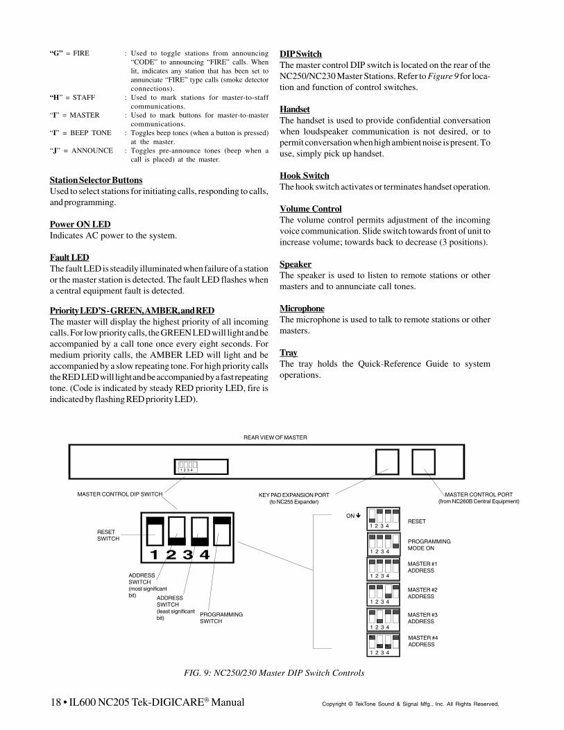
18 • IL600 NC205 Tek-DIGICARE® Manual Copyright © TekTone Sound & Signal Mfg., Inc. All Rights Reserved.
“G” = FIRE : Used to toggle stations from announcing“CODE” to announcing “FIRE” calls. Whenlit, indicates any station that has been set toannunciate “FIRE” type calls (smoke detectorconnections).
“H” = STAFF : Used to mark stations for master-to-staffcommunications.
“I” = MASTER : Used to mark buttons for master-to-mastercommunications.
“I” = BEEP TONE : Toggles beep tones (when a button is pressed)at the master.
“J” = ANNOUNCE : Toggles pre-announce tones (beep when acall is placed) at the master.
Station Selector ButtonsUsed to select stations for initiating calls, responding to calls,and programming.
Power ON LEDIndicates AC power to the system.
Fault LEDThe fault LED is steadily illuminated when failure of a stationor the master station is detected. The fault LED flashes whena central equipment fault is detected.
Priority LED’S - GREEN, AMBER, and REDThe master will display the highest priority of all incomingcalls. For low priority calls, the GREEN LED will light and beaccompanied by a call tone once every eight seconds. Formedium priority calls, the AMBER LED will light and beaccompanied by a slow repeating tone. For high priority callsthe RED LED will light and be accompanied by a fast repeatingtone. (Code is indicated by steady RED priority LED, fire isindicated by flashing RED priority LED).
FIG. 9: NC250/230 Master DIP Switch Controls
ADDRESSSWITCH(most significantbit) ADDRESS
SWITCH(least significantbit)
PROGRAMMINGSWITCH
RESETSWITCH
REAR VIEW OF MASTER
MASTER CONTROL DIP SWITCH KEY PAD EXPANSION PORT(to NC255 Expander)
MASTER CONTROL PORT(from NC260B Central Equipment)
1 2 3 4
1 2 3 4
1 2 3 4
ON #RESET
PROGRAMMINGMODE ON
MASTER #1ADDRESS
MASTER #2ADDRESS
MASTER #3ADDRESS
MASTER #4ADDRESS
1 2 3 4
1 2 3 4
1 2 3 4
1 2 3 4
1 2 3 4
DIP SwitchThe master control DIP switch is located on the rear of theNC250/NC230 Master Stations. Refer to Figure 9 for loca-tion and function of control switches.
HandsetThe handset is used to provide confidential conversationwhen loudspeaker communication is not desired, or topermit conversation when high ambient noise is present. Touse, simply pick up handset.
Hook SwitchThe hook switch activates or terminates handset operation.
Volume ControlThe volume control permits adjustment of the incomingvoice communication. Slide switch towards front of unit toincrease volume; towards back to decrease (3 positions).
SpeakerThe speaker is used to listen to remote stations or othermasters and to annunciate call tones.
MicrophoneThe microphone is used to talk to remote stations or othermasters.
TrayThe tray holds the Quick-Reference Guide to systemoperations.

IL600 NC205 Tek-DIGICARE® Manual • 19Copyright © TekTone Sound & Signal Mfg., Inc. All Rights Reserved.
1 2 3 4
Expander #1
ON$
1 2 3 4
Expander #2
ON$
NOTE: Switch settings as shown arefor NC255-50 station expanders.
$
FIG. 10: NC255 Master Expander
3.2 NC255 MASTER EXPANDER
Refer to Figure 10 for NC255 Master Expander DIP switchsettings. A brief description of the operating controls for theNC255 follows.
Station Selector ButtonsUsed to select stations for initiating calls, responding to calls,and programming. The NC255 has 50 buttons.
DIP SwitchThe DIP Switch is located within the NC255 Master Expander.Positions “1” and “2” select the address of expander. Refer toFigure 10.
3.3 MASTER STATION & EXPANDERDISPLAYS
There are three basic levels of calls:
High Priority: FIRE* (supplementary only, see note)CODE
Medium Priority: BATH/EMERGENCYCORD OUT/PRIORITY
Low Priority: PERSONAL ATTENTIONROUTINE
*NOTE: The NC205 is not tested as a fire alarm system and isnot intended as a primary indication means forevacuation.
Call Location: Indicated by the station selector buttons.
Fire Calls: Are indicated by the rapid flashing of the specificstation’s selector button LED, the rapid flashing of the REDpriority LED, and a rapid pulsating call tone.
Code Calls: Indicated by the rapid flashing of the specificstation’s selector button LED, steady illumination of the REDpriority LED, and a rapid pulsating call tone.
Emergency/Bath/Priority/Cord Out Calls: Are indicated bythe medium flashing of the specific station’s selector buttonLED, steady illumination of the AMBER priority LED, and amedium pulsating call tone.
Personal Attention & Routine Calls: Are indicated by theslow flashing of the specific station’s selector button LED, thesteady illumination of the GREEN priority LED, and a slowpulsating call tone (once every eight seconds).
System Fault Indications: System faults are cancelled only atsuch time as the fault is corrected (see Section 5.6-2 forcomplete list of faults). Faults will appear as listed below:
CODE FAULT: Indicated at the Master Station by a solidillumination of the Fault LED. Pressing the Zone Buttontwice will cause the affected station’s selector LED to flashat a slow rate for eight (8) seconds. Refer to section 5.6-2 forfurther information.
- Wires between a code station and a patient station aredefective.
- The code station is defective.- The patient station is defective.
STATION FAULT: Indication at the Master Station thesame as described above. Refer to section 5.6-2 for furtherinformation.
MASTER FAULT: Indication at the Master Station by asolid illumination of the Fault LED. Refer to section 5.6-2 forfurther information.
CENTRAL EQUIPMENT OR MASTER FAULT:Indication by a rapid flashing of the Fault LED at the MasterStation. No indication at the Central Equipment.

20 • IL600 NC205 Tek-DIGICARE® Manual Copyright © TekTone Sound & Signal Mfg., Inc. All Rights Reserved.
3.4 PATIENT STATIONS
TekTone® IR Series Stations use high quality speaker/microphones for voice communications and tone signaling.Due to the high sensitivity of the microphone, it is notnecessary for the patient to move close to the unit or to raisethe voice above a normal speaking level to be heard.
Refer to Figure 11 for locations and names of controls andindicators. A brief description of the operating controls for thepatient stations follows:
3.4-1 IR251/IR252 Standard Stations
These stations do not provide supervision circuitry, outputsfor three or four lamp dome lights, or inputs for presence andcode stations.
Reset Button/In-Use LEDThe “RESET” button is used to cancel a call placed from thestation. The LED illuminates whenever communication to themaster station is engaged.
Call-Placed LEDThe “CALL-PLACED” LED is steadily illuminated whenevera call is placed from the station and flashes slowly during a cordout condition.
Call Cord ReceptacleThere are two kinds of call cord receptacles. The modular(rectangular) type is for use with SF301P Pillow Speakers orSF311/SF312 Call Cords. The 1/4" phone jack (round) type isfor use with SF301/SF302 Call Cords. Single bed stations haveone call cord receptacle; dual bed stations have two.
3.4-2 IR255-IR258 Enhanced Stations
These stations provide outputs for three or four lamp domelights, and additional inputs for presence stations, codestations, and smoke detectors. These stations provide circuitryfor supervision of code station and associated wiring. Powerand select wires are supervised by central equipment.
Reset Button/In-Use LEDThe “RESET” button is used to cancel a call placed from thestation. The LED illuminates whenever communication to themaster station is engaged. The “RESET” button can also beused to cancel a staff request at a station.
Call-Placed LEDThe “CALL-PLACED” LED is steadily illuminated whenevera call is placed from the station. The LED flashes when a callcord is pulled from its socket.
Call Cord ReceptacleThere are two kinds of call cord receptacles. The modular(rectangular) type is for use with SF301P Pillow Speakers orSF311/SF312 Call Cords. The 1/4" phone jack (round) type isfor use with SF301/SF302 Call Cords. Single bed stations haveone call cord receptacle; dual bed stations have two.
IR257 IR258
IR251/IR255 IR252/IR256
% "
% "CALL CORD
RECEPTACLES
# #
# #
##
IN USE LED
# #CALL-PLACED
LED
CALL-PLACEDLED
CALL CORDRECEPTACLES
IN USE LED
FIG. 11: IR251/IR252 Standard and IR255/IR256/IR257/IR258 Enhanced Patient Stations

IL600 NC205 Tek-DIGICARE® Manual • 21Copyright © TekTone Sound & Signal Mfg., Inc. All Rights Reserved.
3.5 IR250 STANDARD/IR254 ENHANCEDSTAFF & IR260A DUTY STATIONS
The IR250 does not provide supervision circuitry, outputs forthree or four lamp dome lights, or inputs for presence and codestations. These features are found on the IR254. Refer toFigure 12 for locations and names of controls and indicators.A brief description of the operating controls for the staff andduty stations follows:
Reset Button/In-Use LEDThe “RESET” button is used to cancel a call placed from thestation. The LED illuminates whenever communication to themaster station is engaged. (See special features below foradditional uses of the “RESET” button on the IR260A DutyStation.)
Call Button/Call-Placed LEDThe “CALL” button is used to place a call to the master. TheLED illuminates when a call is placed.
IR260A Duty Station Special FeaturesThe IR260A does not provide supervision circuitry or inputs forpresence and code stations. The “RESET” button may be usedto silence the tone signal for low priority calls. Medium and highpriority tone signals cannot be silenced. The tone will return onlyafter all low priority calls have been cancelled, or a medium or highpriority call is placed.
Low Priority Calls: A call tone is repeated once every 8seconds.
Medium Priority Calls: The “EMERGENCY” LED will flashand a slow, repeating tone is heard from the speaker.
High Priority Calls: The “EMERGENCY” LED will flash anda fast repeating tone is heard from the speaker.
Fire: The “EMERGENCY” LED will flash at a fast rate and a fastrepeating tone will be heard from the speaker.
3.6 IR253 STANDARD PULL CORDPATIENT STATION
The IR253 does not provide supervision circuitry, outputs forthree or four lamp dome lights, or inputs for presence and codestations. Refer to Figure 13 for locations and names ofcontrols and indicators. A brief description of the operatingcontrols for the pull cord patient station follows:
Reset Button/In-Use LEDThe “RESET” button is used to cancel a call placed from thestation. The LED illuminates whenever communication to themaster station is engaged.
Call-Placed LEDThe “CALL-PLACED” LED is steadily illuminated whenevera call is placed from the station.
Pull CordThe IR253 is supplied with a 6' nylon pull cord and pendant.
IR250/IR254 IR260A
EMERGENCYLED
FIG. 12: IR250 Standard/IR254 Enhanced Staff Stations and IR260A Duty Stations
CALL-PLACEDLED
$$
IN USE LED# #
$
FIG. 13: IR253 Standard Pull Cord Patient Station
IR253
RESETBUTTON
#
CALL-PLACEDLED%
PULLCORD
%
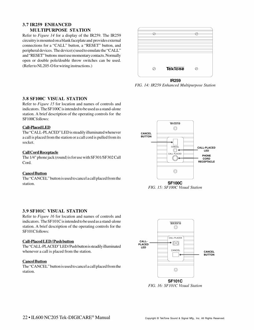
22 • IL600 NC205 Tek-DIGICARE® Manual Copyright © TekTone Sound & Signal Mfg., Inc. All Rights Reserved.
3.7 IR259 ENHANCEDMULTIPURPOSE STATION
Refer to Figure 14 for a display of the IR259. The IR259circuitry is mounted on a blank faceplate and provides externalconnections for a “CALL” button, a “RESET” button, andperipheral devices. The device(s) used to emulate the “CALL”and “RESET” buttons must use momentary contacts. Normallyopen or double pole/double throw switches can be used.(Refer to NL205-O for wiring instructions.)
3.8 SF100C VISUAL STATIONRefer to Figure 15 for location and names of controls andindicators. The SF100C is intended to be used as a stand-alonestation. A brief description of the operating controls for theSF100C follows:
Call-Placed LEDThe “CALL-PLACED” LED is steadily illuminated whenevera call is placed from the station or a call cord is pulled from itssocket.
Call Cord ReceptacleThe 1/4" phone jack (round) is for use with SF301/SF302 CallCord.
Cancel ButtonThe “CANCEL” button is used to cancel a call placed from thestation.
3.9 SF101C VISUAL STATIONRefer to Figure 16 for location and names of controls andindicators. The SF101C is intended to be used as a stand-alonestation. A brief description of the operating controls for theSF101C follows:
Call-Placed LED / Push buttonThe “CALL-PLACED” LED / Push button is steadily illuminatedwhenever a call is placed from the station.
Cancel ButtonThe “CANCEL” button is used to cancel a call placed from thestation.
IR259FIG. 14: IR259 Enhanced Multipurpose Station
FIG. 15: SF100C Visual Station
CANCEL
CALL PLACED
SF100C
%CALL-PLACED
LED
"
CANCELBUTTON
%PHONECORD
RECEPTACLE
SF101CFIG. 16: SF101C Visual Station
"CALL-PLACED
LED
%
CANCELBUTTON
CALL PLACED
CANCEL
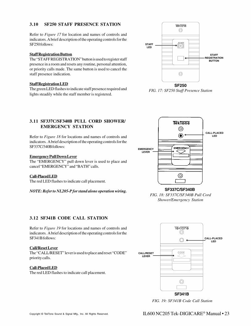
IL600 NC205 Tek-DIGICARE® Manual • 23Copyright © TekTone Sound & Signal Mfg., Inc. All Rights Reserved.
3.10 SF250 STAFF PRESENCE STATION
Refer to Figure 17 for location and names of controls andindicators. A brief description of the operating controls for theSF250 follows:
Staff Registration ButtonThe “STAFF REGISTRATION” button is used to register staffpresence in a room and resets any routine, personal attention,or priority calls made. The same button is used to cancel thestaff presence indication.
Staff Registration LEDThe green LED flashes to indicate staff presence required andlights steadily while the staff member is registered.
3.11 SF337C/SF340B PULL CORD SHOWER/EMERGENCY STATION
Refer to Figure 18 for locations and names of controls andindicators. A brief description of the operating controls for theSF337C/340B follows:
Emergency Pull Down LeverThe “EMERGENCY” pull down lever is used to place andcancel “EMERGENCY” and “BATH” calls.
Call-Placed LEDThe red LED flashes to indicate call placement.
NOTE: Refer to NL205-P for stand alone operation wiring.
3.12 SF341B CODE CALL STATION
Refer to Figure 19 for locations and names of controls andindicators. A brief description of the operating controls for theSF341B follows:
Call/Reset LeverThe “CALL/RESET” lever is used to place and reset “CODE”priority calls.
Call-Placed LEDThe red LED flashes to indicate call placement.
"EMERGENCY
LEVER
%CALL-PLACED
LED
SF337C/SF340BFIG. 18: SF337C/SF340B Pull Cord
Shower/Emergency Station
CODE"
CALL/RESETLEVER
%CALL-PLACED
LED
SF341B
FIG. 19: SF341B Code Call Station
STAFF
FIG. 17: SF250 Staff Presence StationSF250
%
STAFFREGISTRATION
BUTTON
"STAFFLED

24 • IL600 NC205 Tek-DIGICARE® Manual Copyright © TekTone Sound & Signal Mfg., Inc. All Rights Reserved.
3.13 LI SERIES CORRIDOR DOME/ZONELIGHTS
The LI381/LI382/LI383/LI387/LI388A Corridor Dome/ZoneLights provide for indications of call origin, call priority, andstaff presence through the use of red, green, blue, and whitelamps. When used in association with a remote station, all callsoriginating from that room will be indicated by lamp signal(s).
Dome LightsThe LI381 consists of one incandescent light (white); LI382consists of two incandescent lights (white and red); and theLI383 consists of three lights (red, green, and white). All arecovered by one single polystyrene lens. (Refer to Figure 20.)
The LI387 consists of four incandescent lights covered bytranslucent polycarbonate (red, green, and blue) andpolystyrene (white) lenses. (Refer to Figure 21.)
Light signals for the LI381/LI382/LI383/LI387 are as follows:
High Priority: FIRE - Red flashing (supplementary only)at fast rate.
* CODE CALL - Blue flashing at fast rate.
Medium Priority: BATH/EMERGENCY - Red flashing* PRIORITY
CORD OUT - White flashing* STAFF REQUEST - Green flashing*CODE FAULT - Blue flashing at slow rate
Low Priority: * PERSONAL ATTN. - White steadyROUTINE - White steady
* STAFF PRESENT - Green steady
*These light signals are available only on IR254-IR259Enhanced Patient Stations.
Refer to wiring diagrams for wiring outputs provided for domelight indication.
Zone LightsThe LI387 and LI388A consist of four incandescent lightscovered by translucent polycarbonate (red, green, and blue)and polystyrene (white) lenses. (Refer to Figure 21.)
When the LI387 is used with an IR260A Duty Station, all callsoriginated from the zones to which the duty station is assignedwill be indicated by light signal(s) .
The LI388A is a stand alone zone activity indicator thatperforms the same light signaling functions as an LI387/IR260A combination.
Light signals for the LI387/IR260A and LI388A are as follows:
Highest Priority: FIRE - Red flashing (supplementary only)at fast rateCODE CALL - Blue flashing at fast rateBATH/EMERGENCY/CORD OUT- Red flashing at slow rateSTAFF REQUEST - Green flashing atslow ratePERSONAL ATTN/ROUTINE- White steady
Lowest Priority: STAFF PRESENT - Green steady
The LI388A and LI387/IR260A will indicate the highest priorityof all calls in the zones to which they are programmed torespond.
NOTE: Any LI Series Dome Light can function as a zonelight when used in conjunction with an IR260ADuty Station. Only calls associated with the light’scolor (red, green, or white) will be displayed.
FIG. 20: LI381/LI382/LI383 Corridor Dome/Zone
LI381/LI382/LI383
FIG. 21: LI387/LI388A Corridor Dome/ZoneLI387/LI388A
&
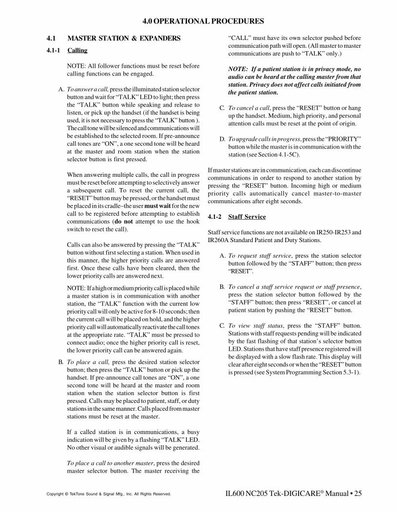
IL600 NC205 Tek-DIGICARE® Manual • 25Copyright © TekTone Sound & Signal Mfg., Inc. All Rights Reserved.
4.1 MASTER STATION & EXPANDERS
4.1-1 Calling
NOTE: All follower functions must be reset beforecalling functions can be engaged.
A. To answer a call, press the illuminated station selectorbutton and wait for “TALK” LED to light; then pressthe “TALK” button while speaking and release tolisten, or pick up the handset (if the handset is beingused, it is not necessary to press the “TALK” button ).The call tone will be silenced and communications willbe established to the selected room. If pre-announcecall tones are “ON”, a one second tone will be heardat the master and room station when the stationselector button is first pressed.
When answering multiple calls, the call in progressmust be reset before attempting to selectively answera subsequent call. To reset the current call, the“RESET” button may be pressed, or the handset mustbe placed in its cradle–the user must wait for the newcall to be registered before attempting to establishcommunications (do not attempt to use the hookswitch to reset the call).
Calls can also be answered by pressing the “TALK”button without first selecting a station. When used inthis manner, the higher priority calls are answeredfirst. Once these calls have been cleared, then thelower priority calls are answered next.
NOTE: If a high or medium priority call is placed whilea master station is in communication with anotherstation, the “TALK” function with the current lowpriority call will only be active for 8-10 seconds; thenthe current call will be placed on hold, and the higherpriority call will automatically reactivate the call tonesat the appropriate rate. “TALK” must be pressed toconnect audio; once the higher priority call is reset,the lower priority call can be answered again.
B. To place a call, press the desired station selectorbutton; then press the “TALK” button or pick up thehandset. If pre-announce call tones are “ON”, a onesecond tone will be heard at the master and roomstation when the station selector button is firstpressed. Calls may be placed to patient, staff, or dutystations in the same manner. Calls placed from masterstations must be reset at the master.
If a called station is in communications, a busyindication will be given by a flashing “TALK” LED.No other visual or audible signals will be generated.
To place a call to another master, press the desiredmaster selector button. The master receiving the
“CALL” must have its own selector pushed beforecommunication path will open. (All master to mastercommunications are push to “TALK” only.)
NOTE: If a patient station is in privacy mode, noaudio can be heard at the calling master from thatstation. Privacy does not affect calls initiated fromthe patient station.
C. To cancel a call, press the “RESET” button or hangup the handset. Medium, high priority, and personalattention calls must be reset at the point of origin.
D. To upgrade calls in progress, press the “PRIORITY”button while the master is in communication with thestation (see Section 4.1-5C).
If master stations are in communication, each can discontinuecommunications in order to respond to another station bypressing the “RESET” button. Incoming high or mediumpriority calls automatically cancel master-to-mastercommunications after eight seconds.
4.1-2 Staff Service
Staff service functions are not available on IR250-IR253 andIR260A Standard Patient and Duty Stations.
A. To request staff service, press the station selectorbutton followed by the “STAFF” button; then press“RESET”.
B. To cancel a staff service request or staff presence,press the station selector button followed by the“STAFF” button; then press “RESET”, or cancel atpatient station by pushing the “RESET” button.
C. To view staff status, press the “STAFF” button.Stations with staff requests pending will be indicatedby the fast flashing of that station’s selector buttonLED. Stations that have staff presence registered willbe displayed with a slow flash rate. This display willclear after eight seconds or when the “RESET” buttonis pressed (see System Programming Section 5.3-1).
4.0 OPERATIONAL PROCEDURES

26 • IL600 NC205 Tek-DIGICARE® Manual Copyright © TekTone Sound & Signal Mfg., Inc. All Rights Reserved.
4.1-3 Paging
Paging communications are uni-directional (master-to-stations). See System Configuration/Programming Section5.2-1 for Programming Station Zone Assignments.
A. To page a specific zone, press the “PAGE” buttonfollowed by the numerical button (“1”-“8”)representing the requested zone. Note: Stations pagedmust also be on the same selector card.
B. To page master preset zones, press the “PAGE”button followed by the “ZONE” button. This will pageall zones in the master’s current setup.
C. To page all stations on the system “ALL CALL”, pressthe “PAGE” button followed by the numerical “9” key.NOTE: Only one master at a time, per system, maybe in paging communications.
D. To page a staff member, press the “PAGE” buttonfollowed by the “STAFF” button. This will open audiocommunications with all stations marked as staffstations and all stations where staff presence isregistered.
E. To discontinue paging, press “RESET”.
4.1-4 Follower Functions
A. To follow a staff member, press the “FOLLOW”button followed by the “STAFF” button. Call toneswill be sent to rooms in the preset zones where staffpresence is registered, as well as stations that aremarked as staff stations.
B. To follow to a specific room, press the “FOLLOW”button, then select the room. Call tones will be sent tothe selected room only.
C. To discontinue the follower function, press “RESET”.
4.1-5 Station Functions
A. To view a station’s zone assignments and status,press the individual station’s selector button followedby the“ZONE” button. A display will appear showingthe zones assigned to the station in the numerical keycolumn. The alpha key column will display the station’sstatus indicators. Press “RESET” when finished.
NOTE: Station’s selector button LED will lightmomentarily and then extinguish before the zoneinformation is retrieved. (See System Configuration/Programming Section 5.2-1.)
B. To view and/or change stations in privacy mode,press the “PRIVACY” button. Stations in privacymode will display with a flashing LED on their selectorbutton. This display will clear after eight seconds orwhen the “RESET” button is pressed. To place astation in privacy mode, the station must first beselected and “PRIVACY” pressed followed by“RESET”. This same procedure is used to release astation from the privacy mode.
C. To change the priority status of a station, press thestation’s selector button followed by the “PRIORITY”button; then press “RESET”. This will upgrade thestation’s low priority call from a Routine level toPersonal Attention which must be reset at the station(Personal Attention not available on IR250-IR253 andIR260A.) Pressing the station’s selector button,“PRIORITY”, and then “RESET” again (immediatelyfollowing the first upgrade) will upgrade the station’slow priority call from a Personal Attention level toPriority—the call will register at the master as amedium priority call and must be reset at the station.Following the select- “PRIORITY” - “RESET”procedure, once again will revert the station’s statusback to a Routine level for low priority calls. For IR250-IR253 and IR260A Standard and Duty Stations, followthe same procedure as above. However, these stationsonly have Routine and Priority levels.
D. To view the priority status of stations, press the“PRIORITY” button. Stations upgraded to Prioritywill be indicated by the fast flashing of that station’sselector button LED. Stations that have been upgradedto Personal Attention will be displayed with a slowflash rate (excludes IR250-IR253 and IR260A). Thisdisplay will clear after eight seconds or when the“RESET” button is pressed.
4.1-6 Master Functions
A. To enable room monitoring, simply press the desiredstation selector button(s). Multiple rooms (up to amaximum of 20) may be monitored by simply selectingthem one after another (all stations must be on thesame selector card and in the same zone). Press the“RESET” button to discontinue the monitor function.
B. To view the master’s zone assignments and status,press the “ZONE” button. A display will appearshowing the zones assigned to the master in thenumerical key column. (The alpha key column willdisplay the master’s status indicators. See SystemConfiguration/Programming Section 5.1-1.) Press“RESET” to conclude this function.

IL600 NC205 Tek-DIGICARE® Manual • 27Copyright © TekTone Sound & Signal Mfg., Inc. All Rights Reserved.
4.2 IR SERIES STATIONS
To reply to a call, speak in a normal voice when spoken to.
To cancel a call (excluding IR259), press the “RESET” buttonlocated on the front faceplate of the station. To cancel a“CORD OUT”, simply reinsert the call cord plug into itsreceptacle.
4.2-1 IR251/IR252 Standard and IR255/IR256Enhanced Patient Stations
A. To place a call, press the “CALL” button located onthe end of the call cord. A medium priority call willautomatically be placed if the call cord is pulled fromits receptacle (“CORD OUT”).
B. To cancel a call, press the “RESET” button locatedon the front faceplate of the station.
4.2-2 IR257/IR258 Enhanced Patient StationsA. To place a call, press the red “CALL” button located
on the SF Series Pillow Speaker. A medium priority callwill automatically be placed if the call cord is pulledfrom its receptacle (“CORD OUT”).
B. To control the television, press the “TV” buttonlocated on the SF Series Pillow Speaker. If the TV is off,pressing this button will turn it on. Continue pressingthis button until the desired channel is reached. TheTV will turn off when the “OFF” channel is selectedon the TV. The volume control will adjust only theTV’s volume.
C. To cancel a call, press the “RESET” button locatedon the front faceplate of the station.
4.2-3 IR250 Standard & IR254 Enhanced Staff Stations
A. To place a call, press the yellow “CALL” buttonlocated on the faceplate of the station.
B. To cancel a call, press the “RESET” button locatedon the front faceplate of the station.
4.2-4 IR253 Standard Pull Cord Station
A. To place a call, pull the call cord.
B. To cancel a call, press the “RESET” button locatedon the front faceplate of the station.
4.2-5 IR259 Enhanced Multipurpose Station
A. To place a call, the device connected to the IR259must be activated.
B. To cancel a call, deactivate the device.
4.2-6 IR260A Duty Station
A. To place a call, press the yellow “CALL” buttonlocated on the faceplate of the station.
B. To adjust the announcement volume, move thesupplied jumper to the appropriate position on the 3-pin header of the IR260A (see Volume Settings andAdjustments Section 2.7, Figure 7).
C. To cancel a call, press the “RESET” button locatedon the front faceplate of the station.
4.3 SF SERIES PERIPHERAL STATIONS
4.3-1 SF100C Visual Station
A. To place a call, press the “CALL” button located onthe end of the call cord. A low priority call willautomatically be placed if the call cord is pulled fromits receptacle (“CORD OUT”).
B. To cancel a call, press the “CANCEL” button.
4.3-2 SF101C Visual Station
A. To place a call, press the “CALL” button. The “CALL”button will light to indicate a call has been placed.
B. To cancel a call, press the “CANCEL” button.
4.3-3 SF250 Staff Presence Station
A. To register staff presence, push the button under the“STAFF” LED.
B. To clear staff presence, push the button under the“STAFF” LED.
C. To clear a staff request at a station, press the “RESET”button on the station (IR254-IR258).
4.3-4 SF337C/SF340B Pull Cord Shower/Emergency Station
Calls made from these stations must be reset at the point of origin.
A. To place a call, pull down the red “EMERGENCY”lever or pull the call cord.
B. To cancel a call, push the red “EMERGENCY” leverto the up position.
4.3-5 SF341B Code Call Station
A. To place a call, pull down the blue “CODE” lever orpull the call cord.
B. To cancel a call, push the blue “CODE” lever to theup position.

28 • IL600 NC205 Tek-DIGICARE® Manual Copyright © TekTone Sound & Signal Mfg., Inc. All Rights Reserved.

IL600 NC205 Tek-DIGICARE® Manual • 29Copyright © TekTone Sound & Signal Mfg., Inc. All Rights Reserved.
STATUS
PRIVACY
P A G E
INHIBIT
S T A N DA L O N E
BATH
FAULT
D E F E A T
FIRE
M A S T E RSTATION
Z O N E
# 1
# 2
# 3
# 4
# 5
# 6
#7
# 8
ALL
PRIORITY
U P G R A D E
( )
STAFF
STATION
NUMERICALKEY COLUMN
INSERT%
A
B
C
D
E
F
G
H
I
J
0
1
2
3
4
5
6
7
8
9
%
ALPHAKEY COLUMN
INSERT
FIG. 22: NC250/230 Programming Inserts
MASTER FUNCTIONS
%
%
BEEP TONE
PRE-ANNOUNCE
5.0 SYSTEM CONFIGURATION/PROGRAMMING
The following information should be programmed into the NC205 System by qualified administrative personnel prior to generalstaff operation. Figure 22 shows the NC250/NC230 Master Station inserts included for system programming. The personnelresponsible for programming should see to it that these inserts are not destroyed, distributed, or changed. Informationprogrammed after this time should require few changes. During programming, please ensure that all key strokes are deliberateand that there is a momentary pause between operations.
C. To program master status, press the correspondingalpha key for:
PRESETS = “A” - “H”These keys indicate the alpha keys usedfor preset zones. “A” is the default preset.
BEEP TONE = “I”When lit, this key indicates that a buttonpushed on the master keypad will generatea short beep tone. To turn off this feature,press the alpha key so that the LED is off.
PRE-ANNOUNCE TONE = “J”When lit, this key indicates that a call toneis introduced at both the station and themaster when a call is placed. To turn offthis feature, press the alpha key so thatthe LED is off.
D. To view station fault list, press the “ZONE” buttonwhile in the master programming mode. Stations thathave reported a fault since the last fault scan willappear with rapidly flashing LED’s. Press the “ZONE”button again to return to the master programmingmode (display will clear itself after eight seconds).
5.1-2 Exiting the Programming Mode
To exit the programming mode, press the “RESET” button.(The display will clear eight seconds after entering theprogramming mode.)
The numerical selector button LED’s are the first column ofLED selector buttons on the NC250/NC230 Master Station.The alpha selector button LED’s are the second column of LEDselector buttons. These columns serve dual purposes; thenumerical column serves as zone programming switches, thealpha column serves as master and station status programmingswitches, and both columns serve as normal station selectorbuttons.
5.1 MASTER STATIONS
Zoning assignments are for use in controlling the patient,staff, and duty stations to which the master station maycommunicate. They may also be used to control paging, stafffollower, and other system functions. Master stations may beassigned to one, all, or any combination of the eight zonessupported by the NC205 System. Master stations default to alleight zones.
In multiple master systems only one conversation to one ofeight audio paths may occur. The stations are pre-wired tothese paths through the default hardware zone number of thePM261A Selector Card to which it is connected (each cardrepresents one audio path/hardware zone).
Refer to Section 5.3 for additional features such as making asystem non-square, adding an expansion keypad, etc. Refer toSection 5.5 for instructions on adding master stations to asystem.
5.1-1 Entering the Programming Mode
To configure the master, press the “ZONE” key (system mustbe on but not being used). A display will appear showing thepre-programmed zones in the numerical key column. Thestatus of the master is displayed in the alpha key column. Oncethese displays have appeared, the master is in the programmingmode.
A. To select zone presets, press the desired alpha key.The zones assigned to this alpha preset are thendisplayed in the numerical key column (the master willrespond to only these zones). Alpha keys “A” - “H”are used for these zone presets.
B. To program master zones, press zone key 2 moretimes, then press the numerical key that correspondsto number of the zone. If the zone is programmed, thatnumber’s LED will light. Pressing the numerical keyagain will turn off the LED and unprogram that zone.A display of “ZONE # 0” indicates that no zones areprogrammed (master is off-line). Pressing the “9” keywill set all zones “ON”.

30 • IL600 NC205 Tek-DIGICARE® Manual Copyright © TekTone Sound & Signal Mfg., Inc. All Rights Reserved.
5.2 PATIENT STATIONS
Assign station zone assignments following the procedureslisted below. The NC205 System should be on but not in usewhile zone assignments are being entered.
Zoning assignments for each station default to the selectorcard number they have been connected to (in the NC260BCentral Equipment or NC262A Central Equipment Expander).Stations must be assigned to at least one of the eight zonessupported by the NC205 System, but may be assigned toadditional zones, if desired. Zoning assignments are used todirect station calls to masters that are zoned for those calls.
5.2-1 Entering the Programming Mode
To choose the station to be programmed, press the appropriatestation selector button on the NC250/NC230/NC255. The LEDassociated with that selector button will light as the centralequipment establishes communications with the station. Nowpress the “ZONE” button. The station LED will extinguish anda display showing the zones assigned to the station will appearin the numeric key column; the station’s status will display inthe alpha key column.
To recall what station is being programmed, simply push the“ZONE” button again. This will temporarily light the LED ofthe station originally chosen with a rapid flash. Press the“ZONE” button again to return to programming (display willclear after eight seconds).
A. To assign zones, press the numerical key thatcorresponds to the number of the desired zone. If thezone is programmed, that number’s LED will light.Pressing the numerical key again will turn off the LEDand unprogram that zone. Pressing the “9” key willtoggle the state of all zones.
NOTE: DO NOT assign “ZONE 0” to stations; this willrender them off-line. To reactivate a station that hasbeen taken off-line, place a call from that station or re-assign it to a zone other than “0”. The central equipmentwill then validate the station and assign it to all zones.
B. To program station status, press the correspondingalpha key:
“A” = STATUSWhen lit, this key indicates that the stationis in a standard mode of operation; nospecial functions (“B” - “I”) have beenassigned. IR254-259 Stations default tothe “A” Status. IR250-253 and IR260AStations default to “F” (Fault Defeat) and“G” (Fire).
“B”= PRIVACYWhen lit, this key indicates that audiocommunications from the station areinhibited. If a call originates from thestation, then normal two-waycommunications are established. If thecall originates from a master, then noaudio will be heard from the station at themaster, but audio from master will beheard at station.
“C” = PAGE INHIBITWhen lit, this key indicates that pagingfunctions (preset, zone, and all-callpaging) are ignored by the station.
“D” = PRIORITY UPGRADEThis key is used to indicate that a station’sRoutine call has been upgraded to thePriority level.(Used for IR250-IR253 andIR260A only).
“E” = BATH (STAND ALONE)This key is used to mark devices(Emergency Call Stations, SmokeDetector Contacts, etc.) as standalone bath/emergency s tat ions.These stations will generate mediumpriority (EMERGENCY) calls. Bydefault, stand alone stations that arenot marked as BATH/STAND ALONEwill generate high priority (CODE orFIRE) calls.
“F” = FAULT DEFEATThis key is used to disable the centralequipment’s fault scan for the station. Itcan be used to temporarily mask a faultystation while repairs are underway. Thiskey must be set for all IR250/IR251/IR252/IR253, IR260A and stand alonedevices.
“G” = FIREWhen lit, this key indicates that highpriority calls from this station arerecognized as FIRE calls. (NOTE: TheNC205 is not listed as a fire alarm system.It is not intended as a primary indicationmeans for evacuation.)
“H” = STAFF STATIONThis key is used to mark a station as aSTAFF station. The stations will be includedin staff paging and follow functions.
“I” = MASTER STATIONThis key is used to assign a selectorbutton to a master for master-to-mastercommunications. All masters must havethe same assigned room number (251-254) available. Refer to Section 5.3-1.

IL600 NC205 Tek-DIGICARE® Manual • 31Copyright © TekTone Sound & Signal Mfg., Inc. All Rights Reserved.
To turn off any feature, simply press its associatedalpha key so that its LED is off. Widely usedprogramming functions (PRIVACY, PRIORITYUPGRADE, etc.) should be accomplished by use of themaster function keys so marked.
C. To program a selector key for master-to-mastercommunication, press “I” to mark the key as a master.Then press the numerical number of the desiredmaster (1 through 4). All masters must be programmedto have their own selector buttons, in addition toselector buttons representing other masters. Forexample, if master-to-master communication is desiredon a system with only two masters, each master musthave one selector button programmed for itself andanother selector button programmed for the othermaster. (Note: 251, 252, 253, 254 are the default keysfor master-to-master communication. 251 is used formaster #1, 252 for master #2, and so on.)
NOTES: Master-to-master communications arerestricted to “push-to-talk” only (no handset). SeeSection 5.3 for additional details.
Using this method, all master-to-mastercommunications can be programmed at one master. Atall other masters, the same buttons are programmedautomatically for each master.
5.2-2 Exiting the Programming Mode
To exit the programming mode, press the “RESET” button.The “RESET” LED will flash until the information has beenstored.
5.3 MASTER KEY PROGRAMMING/CON-FIGURATION
The NC250/NC230 Master Stations provide extended featuresto allow non-square system configurations, easy keypadexpansion, and custom key configurations.
This section explains the methods used to accomplish thesefunctions.
5.3-1 Entering the Programming Mode
NOTE: When erasing the flash memory or adding an expansionkeypad, custom configurations (“non-square” and/or “specificselector buttons”) must be reprogrammed. Duringprogramming, the fault light may illuminate momentarily–anormal condition.
To place a master station into the programming mode, turnon (down) the programming switch SW4, as shown in Figure23. The following features are then available:
A. To reset a master station to default values (erase flashmemory), turn SW4 on, toggle SW1, wait for “TALK”LED to light (indicating proper operation) and turnSW4 off.
By default, masters begin room numbering at the firstcolumn’s top selector button and continue from topto bottom, left to right, until all keys have beennumbered (including all expansion keypads). Otherdefault values include PRESET “A” on, BEEP TONEon, and PRE-ANNOUNCE TONE off.
FIG. 23: NC250/230 Master DIP Switch Controls
1 2 3 4
ON # MASTERRESET
PROGRAMMINGMODE ON
MASTER #1ADDRESS
MASTER #2ADDRESS
MASTER #3ADDRESS
MASTER #4ADDRESS
REAR VIEW OF MASTER
MASTER CONTROL DIP SWITCH
KEY PAD EXPANSION PORT(to NC255 Expander)
MASTER CONTROL PORT(from NC260B Central Equipment)
1 2 3 4
1 2 3 4
1 2 3 4
1 2 3 4
1 2 3 4
MASTER CONTROL DIP SWITCH
1 2 3 4

32 • IL600 NC205 Tek-DIGICARE® Manual Copyright © TekTone Sound & Signal Mfg., Inc. All Rights Reserved.
B. To add an expansion keypad (NC255) connect tomaster and refer to section 5.5-4.
C. To make a master “non-square”, press the ZONEbutton, then key in the numerical value of the roomnumber that the master is to begin from. The TALKLED will flash and a beep tone will sound when theinformation has been accepted. The programmingmode may then be exited.
The term “non-square” means that the master canbegin its selector key assignment from a room numberother than #1. For example, to program an NC250master (50 key) to begin responding with room number15, follow the procedures listed above. Key in “0”, “1”,and “5” for the numerical room value. When completed,the master will respond to rooms 15 (first selectorbutton) through 65 (last selector button).
D. To custom configure a specific selector button, pressthe target selector button. Using the numerical keycolumn, key in the desired value of the room to whichthe target selector key will be assigned. The TALKLED will flash and a beep tone will sound when theinformation has been accepted. The programmingmode may then be exited.
The procedure described above can be used to assignindividual out of sequence room numbers to a selectorbutton. The same procedure is used to mark a selectorbutton as a master station for master-to-mastercommunication. Room numbers 251, 252, 253, and 254are reserved for masters #1, #2, #3, and #4 respectively.Do not use these room numbers for any other purposes.(Refer to Section 5.2-1C.)
NOTE: Using this method, the master-to-mastercommunications must be programmed at each master.This method is useful if the same buttons for master-to-master communication cannot be used at eachmaster.
E. To set the system time, flip dipswitch #4 down, pressthe “Privacy” button. Enter a two digit hour settingusing the numeric keys, and then enter a two digitminute setting using the numeric keys. Finally, setAM or PM by pressing the “0” key for AM or the “1”key for PM. Return dipswitch #4 to its original position.The programming mode may then be exited.
5.3-2 Exiting the Programming Mode
To exit the programming mode, return SW4 to the off positionand then toggle SW1. This procedure releases the master fromprogramming mode and then resets it.
5.4 EQUIPMENT RESET PROCEDURES
5.4-1 Central Equipment
A. To reset the central equipment, remove batteries andpower down the entire system. Then wait 30 secondsbefore reapplying power, and reinstall batteries.
B. To reset the flash memory, turn SW1 on and powerdown the system per 5.4-1A. Wait until LED’s on thePM261A Selector Card begin to flash, then turn SW1off.
C. To disable system programming from masters(programming lock), turn SW2 on.
5.4-2 Master Stations
A. To reset a master, toggle SW1 (see figure 9).
B. To erase flash memory, refer to section 5.3-1A.
5.5 EXPANDING/UPGRADING THESYSTEM
The NC205 Nurse Call System provides features to allow easyupgrading and expansion. This section explains the methodsused to accomplish these functions. The system capacity is128 stations including the master stations.
5.5-1 Adding Central Equipment Expander
A. Inspect and confirm wiring.
B. Disconnect system power at the central equipment(including backup batteries).
C. Make wiring connections in accordance with Section2.6 and wiring diagrams.
D. Once wiring has been validated, power may be reappliedto the system (NC260B, NC262A, and batteries).
E. Reset the flash memory on the NC260B CentralEquipment (Section 5.4-1B).
F. Verify that the activity LED’s on the PM261A SelectorCards are flashing (see Section 7 for testing).

IL600 NC205 Tek-DIGICARE® Manual • 33Copyright © TekTone Sound & Signal Mfg., Inc. All Rights Reserved.
5.5-2 Adding Battery Backup
A. Inspect and confirm wiring.
B. Make wiring connections in accordance with Section2.6 and wiring diagrams.
NOTE: Battery power should be connected after systempower up. If batteries are drained from use, they shouldbe removed to power system back up and then reinsertedinto connector.
5.5-3 Adding Master Stations
A. Inspect and confirm wiring.
B. Disconnect system power at the central equipment(including backup batteries) and NC262A expansionunit.
C. Make wiring connections in accordance with Section2.6, and wiring diagrams.
D. Verify the DIP switch settings on the master to beinstalled. The master’s address should be set to thenext available address (sequentially), the programmingmode should be off, and the reset switch should be up(off).
E. Once the DIP switch settings and wiring have beenvalidated, power may be reapplied to the system(NC260B, NC262A, and batteries).
F. Reset the NC260B Central Equipment. (See Section5.4-1).
5.5-4 Adding Master Expanders
A. Inspect and confirm wiring.
B. Verify the DIP switch settings on the master expanderto be installed. The expander’s address should be setto the next available address (sequentially). Theexpander’s type switch SW4 (“on” for NC255), mustbe set correctly. (Refer to Section 3.2.)
C. Make wiring connections in accordance with Section2.6 and NL205-G.
D. Place NC250/230 Master into the programming mode(see Section 5.3-1, and 5.3-1B).
E. Reset the NC250/NC230 Master (see Section 5.4-2A).The “TALK” LED will flash and a beep tone will soundonce the master has acknowledged the expansion.
F. Return the master to normal operation (see Section5.3-2).
5.5-5 Adding Remote Stations
A. Inspect and confirm wiring.
B. Plug system connector onto station.
C. Place a call from the station. Once the central equipmenthas acknowledged the existence of the call, themaster(s) that have been zoned to respond to callsfrom the station’s zone will display the call. The callmay then be answered from that master (see Section7 for testing).
5.5-6 Adding Peripheral Devices
A. Inspect and confirm wiring.
B. Plug peripheral connector onto station.
C. To test SF Series peripherals, activate the call button,switch, or lever (see Section 7 for testing).
D. To test LI Series peripherals, activate the call(s)associated with the particular lamp(s) color (see Section7 for testing).
E. For stand alone devices, verify that the device isprogrammed for “PRIVACY” and “FAULT DEFEAT”at the associated master station.
5.6 VIEWING SYSTEM INFORMATION
The NC205 Nurse Call System provides various methods ofdisplaying system information. The display pages are timedout and will clear after eight seconds or when the “RESET”button is pressed.
5.6-1 Status Display Pages
A. Privacy display - press the “PRIVACY” key. A displaywill appear showing stations which have been set forPrivacy with a slow flash of the station’s LED.
B. Priority display - press the “PRIORITY” key. Adisplay will appear showing stations which have beenset for Personal Attention by a slow flashing of thestation’s LED. Stations which have been upgraded toPriority will display a rapid flashing of the station’sLED.
C. Staff display - press the “STAFF” key. A display willappear showing stations which have staff presenceregistered by a slow flashing of the station’s LED.Stations where staff presence is requested will bedisplayed by a rapid flashing of the station’s LED.

34 • IL600 NC205 Tek-DIGICARE® Manual Copyright © TekTone Sound & Signal Mfg., Inc. All Rights Reserved.
5.6-2 Faults
The NC205 System scans for fault conditions approximatelyonce every six minutes. Faults are displayed through LED’s onmaster stations, selector cards, and the central equipment.
Faults are displayed on the NC260B by a row of three LED’s,(D1, D2, & D3–from left to right) located at the bottom centerof the motherboard. These LED’s will show the detected faultcondition via a fault code.
The PM261A Selector Card displays central equipment faultswith a single red LED. If the LED is off or steadily on, this willindicate a problem of the central equipment. A flashing LEDindicates normal operation. Note: the flashing of this LED isirregular.
A. Master station fault - indicated by LED “D1” oncontinuously. Other master stations will light theirfault LED’s.
B. Code circuit fault - indicated by LED’s “D1” and“D2” illuminated. See section 3.3 for indication atmaster station.
Code faults are displayed at stations with LI387 DomeLights by a slow flashing blue lamp. Only IR254/IR255/IR256/IR257/IR258/IR259 stations include codesupervision circuitry.
C. Station fault - indicated by LED’s “D1”, “D2”, and“D3” illuminated. The affected station will be indicatedon the master station via lighting the station’s keypadLED and the “FAULT” LED will be continuouslyilluminated. See section 3.3 for indication at masterstation. This could also indicate a nurse or priority linefault.
All fault indication which has originated from the centralequipment will be indicated by the “FAULT” LED on all masterstations being illuminated continuously. The central equipmentmust then be checked for specific fault indication. The “FAULT”LED flashing at a fast rate will indicate no interrogation fromthe central equipment for more than eight (8) seconds, indicatinga central equipment failure.
To view the fault list, press the master’s “ZONE” button twice.This will display the master’s status information on the firstbutton press; the second button press will display stationsthat have reported faults since the last central equipment faultscan. They will be indicated by a fast flashing of the station’sselector LED. This display will clear after eight seconds, orwhen the “RESET” button is pressed.

IL600 NC205 Tek-DIGICARE® Manual • 35Copyright © TekTone Sound & Signal Mfg., Inc. All Rights Reserved.
6.0 SYSTEM MAINTENANCE INSTRUCTIONS
The following section provides information regarding NC205 System user serviceable parts and their replacement. Anyequipment not listed in this section is not user serviceable and should not be replaced or repaired by other than qualified servicepersonnel.
6.1 NC260B CENTRAL EQUIPMENT& NC262A CENTRAL EQUIPMENTEXPANDER
No user serviceable parts.
6.2 PK261A DOME LIGHT POWER SUPPLY
No user serviceable parts.
6.3 NC250/NC230 MASTER STATIONS &NC255 MASTER STATION EXPANDER
6.3-1 Defective Handset/Cord Replacement
A. To remove cord, grip end of modular plug oncord firmly and squeeze until cord is easilypulled away from handset or base.
B. To replace cord, hold end of plug on the cord,squeeze and push straight into receptacle onhandset or base. Release and plug will click intoplace.
C. To test the handset, place a call to a room stationand attempt communications using the handset(See Section 7.3).
6.3-2 8 PIN Modular Cord
A. To remove cord, grip end of modular connectorfirmly and pull straight away from master station.Repeat for wall plate connection.
B. To replace cord, hold by end of plug and pushstraight into cord jack on station. Plug will clickinto place. Repeat for wall plate connection.
C. To test cord, place a call to the station. The“TALK” LED should illuminate whencommunications have been established. Pushthe reset button to cancel call (see Section 7.3).
6.4 IR SERIES STATIONS
6.4-1 Defective Pillow Speaker Replacement
A. To remove pillow speaker, grip end of modularplug firmly and squeeze until cord can easily bepulled straight away from station.
B. To replace pillow speaker, hold by end of plug,squeeze and push straight into the receptacle onstation. Release and plug will click into place.
C. To test pillow speaker, initiate a call. Call-placedLED should illuminate. Push the reset button tocancel call (see Section 7.4).
6.4-2 Defective Call Cord Replacement
A. To remove call cord, grip end of plug firmly andpull straight away from station.
B. To replace call cord, hold by end of plug andpush straight into the receptacle on station.
C. To test call cord, initiate a call. Call-placed LEDshould illuminate. Push the reset button tocancel call (see Section 7.4).
6.5 SF SERIES STATIONS
No user serviceable parts (for SF100C, see Section6.4-2).
6.6 LI SERIES DOME/ZONE LIGHTS
6.6-1 Defective Lamp Replacement
A. To remove cover, grip firmly by sides andsqueeze. Pull cover away from plate.
B. To remove lamps, hold by glass bulb, push inand rotate counter-clockwise, then pull straightout from metal socket.
C. Remove any bulb covers and replace on newbulbs.
D. To replace lamps, hold by glass bulb, push inand rotate clockwise into socket.
E. To test lamps, place calls at all stations necessaryto test all lamp combinations (see Section 7.6).
F. Replace cover.
NOTE: Replace lamps ONLY with TekTone® partnumber LI028 or approved equal.

36 • IL600 NC205 Tek-DIGICARE® Manual Copyright © TekTone Sound & Signal Mfg., Inc. All Rights Reserved.
6.7 REPLACEMENT PARTS
TekTone® Part No. Description Used For
CA033 4 pin modular cord, coiled NC250/NC230 Master Station Handset
CA037/7 8 pin modular cord, 7' NC250/NC230 Master Station
CA037 8 pin modular cord, 1' 4" (1.3' ) NC255 Master Station Expander
LI028 28 volt incandescent lamp LI381/LI382/LI383/LI387/LI388ADome/Zone Lights
PL467 8 pin modular wall plate NC250/NC230 Master Stations
SF301 call cord with molded push button, 7' IR251/IR252 Standard andIR255/IR256 Enhanced Patient Stations
SF301/10 same as SF301 with 10' cord IR251/IR252 Standard andIR255/IR256 Enhanced Patient Stations
SF301G geriatric push button call cord, 7' IR251/IR252 Standard andIR255/IR256 Enhanced Patient Stations
SF302 dual call cord with molded push buttons, 7' IR251/IR252 Standard andIR255/IR256 Enhanced Patient Stations
SF302/10 same as SF302 with 10' cord IR251/IR252 Standard andIR255/IR256 Enhanced Patient Stations
SF302G geriatric dual push button call cord, 7' IR251/IR252 Standard andIR255/IR256 Enhanced Patient Stations
SF301P pillow speaker with call button & TV controls IR257/IR258 Enhanced Patient Stations
SF301PIR pillow speaker with call button, TV & radio controls IR257/IR258 Enhanced Patient Stations
SF311 call cord with molded push button, IR257/IR258 Enhanced Patient Stationsmodular connection, 7'
SF311/10 same as SF311 with 10' cord IR257/IR258 Enhanced Patient Stations
SF311G geriatric/oxygen call cord IR257/IR258 Enhanced Patient Stations
SF312 dual call cord with molded push buttons, IR257/IR258 Enhanced Patient Stationsmodular connection, 7'
SF312G geriatric/oxygen dual call cord IR257/IR258 Enhanced Patient Stations
TA030 telephone handset NC250/NC230 Master Stations

IL600 NC205 Tek-DIGICARE® Manual • 37Copyright © TekTone Sound & Signal Mfg., Inc. All Rights Reserved.
The following section provides test instructions for determining correct system operation. It is assumed that the systemhardware and wiring has been inspected and approved, and that the system and its components have been set up accordingto Section 5-System Configuration/Programming.
These procedures have been written from the perspective of the user/operator. ONLY QUALIFIED SERVICE PERSONNELSHOULD PERFORM REPAIRS AND/OR MAINTENANCE TO THE SYSTEM. Be sure that power is disconnected (DC, thenAC) before attempting to service the system’s main components (central equipment and expanders).
7.1 SYSTEM INSPECTION
7.1-1 Basic Wiring Check
A. Refer to Section 2.5 for wiring instructions.
B. If faulty or misconnected wiring is suspected,contact a qualified service technician.
7.1-2 Test Setup
Before proceeding with a system test, all systemcomponents should be set to normal operatingconditions as follows:
A. NC255/230/250 Master Station & Expanders:
All function buttons should indicate normaloperation (no LED indication). All selector buttonLED’s should be off. The power LED (green)should be on, the priority LED’s (green, yellow,red) should be off, the function key LED’sshould be off, and there should be no faultindication(s).
B. IR250-IR253 Standard Patient Stations andIR260A Duty Station:
Insert the appropriate call cord in each call cordreceptacle (if applicable). Press the “RESET”(red) button to cancel any errant calls.
C. IR254-IR259 Enhanced Patient Stations:
Insert the appropriate call cord in each call cordreceptacle (if applicable). Press the “RESET”(red) button to cancel any errant calls. Stationpriority should be set to Routine, and stafffunctions should not be active.
D. SF Series Peripheral Stations:
If a call has been activated , reset the station byreturning the call lever/reset switch to the “UP”or “OFF” position. On SF100C/SF101C VisualStation, press the “CANCEL” button. On SF250Presence Stations, the green LED should not beilluminated.
E. LI Series Corridor Dome/Zone Lights:
Dome lights should not be illuminated and Zonelights should show no system activity.
7.1-3 Viewing System Faults
Refer to Section 5.6-1 (Status Display Pages), andSection 5.6-2 (Faults).
7.2 CENTRAL EQUIPMENT ANDEXPANDERS
NOTE: If service is required after reviewing thesesteps, a qualified service technician should be alerted.
7.2-1 NC260B Central Equipment
A. Verify that no faults are being displayed on theNC260B’s motherboard (LED’s D7-D9 asreferenced in Section 5.6-2).
B. Verify that the activity LED’s on all PM261A’s(selector cards) are flashing.
C. Verify all wiring as per wiring diagrams.
7.2-2 NC262A Central Equipment Expander
A. Verify that the activity LED’s on all PM261A’s(selector cards) are flashing.
B. Verify all wiring as per wiring diagrams.
7.2-3 PK261A Dome Light Power Supply
A. Verify that the power LED is lit.
B. Verify all wiring as per wiring diagrams.
7.0 TEST INSTRUCTIONS

38 • IL600 NC205 Tek-DIGICARE® Manual Copyright © TekTone Sound & Signal Mfg., Inc. All Rights Reserved.
7.2-4 PM261A Selector Card
A. Verify that the activity LED’s on all PM261A’s(selector cards) are flashing.
B. Verify volume setting (see Section 2.7).
C. Verify all wiring as per wiring diagrams.
7.3 MASTER STATIONS AND EXPANDERS
Ensure that the “POWER ON” LED is illuminated onthe master station before performing these tests.
7.3-1 Basic Communications
A. Initiate a call from each master station to apatient station as described in the OperationalProcedures (Section 4.1-1). Check for thefollowing at the master station:
1. Room station selector LED is illuminated.2. “TALK” LED steadily illuminated.
B. Press “TALK” (grey) button and check for thefollowing at the master station:
1. “TALK” LED steadily illuminated.2. Audible communications established.
Check for the following at the patient station:
1. Reset/In-use LED steadily illuminated.2. Audible communications established.
C. Press “RESET” (black) button and check for thefollowing at master and patient station:
1. All signals cancelled.
D. Repeat Steps A - C using the handset instead ofthe push-to-talk button.
E. Initiate a call to another master station asdescribed in the Operational Procedures (Section4.1-1). Check for the following at both masterstations:
1. Master station selector LED is illuminated.2. “TALK” LED is steadily illuminated.
Check for the following at the called master station:
1. Audible communications can be established(push-to-talk only, no handset).
F. Press “RESET” (black) button and check for thefollowing at both master stations:
1. All signals cancelled.
7.3-2 Staff Functions
NOTE: The “STAFF” functions are available only onIR254-IR259 Patient Stations.
A. Request staff service by selecting a room forcommunications, then pressing the “STAFF”(green) button. Check for the following at themaster station:
1. The room station’s selector button LED isilluminated.
2. “STAFF” button LED slowly flashing.
Check for the following at the patient station:
1. Green dome light flashing.2. Green LED on presence station flashing.
Check for following at the duty station in thesame zone:
1. Green dome light flashing (all zone lights).2. Slow repeating tone signal (1 every 8 seconds).
B. Press “RESET” (black) button and check for thefollowing at master station:
1. Room station selector LED and “STAFF”LED extinguished.
Check for the following at duty stations andzone lights in the same zone:
1. Green dome light flashing.
C. Cancel the staff service request by selecting thesame room for communications, then pressing“STAFF” (green) button, and then the “RESET”(black) button. Check for the following at masterstation, room stations, dome lights, zone lights,and presence stations:
1. All signals cancelled (lights and tones).
7.3-3 Paging Functions
A. Page a zone by pressing the “PAGE” (violet)button, then pressing a zone number (numericalkey column) as described in the OperationalProcedures (Section 4.1-3). Check for thefollowing at the master station:

IL600 NC205 Tek-DIGICARE® Manual • 39Copyright © TekTone Sound & Signal Mfg., Inc. All Rights Reserved.
1. “PAGE” LED is illuminated.2. “ZONE” LED is illuminated.3. Zone number (numerical key column) is
illuminated.4. “TALK” LED is illuminated.
B. Press “TALK” (grey) button and check for thefollowing at the master station:
1. Audible one-way communicationsestablished to all patient stations withinthe selected zone.
Check for the following at all zoned patient stations:
1. Reset/In-use LED steadily illuminated.2. Audible communication with the master has
been established.
C. Press “RESET” (black) button and check for thefollowing at master and patient stations:
1. All signals cancelled.
D. Page all preset zones by pressing “PAGE” (violet)button, and then pressing the “ZONE” (blue)button. Check for the following at the masterstation:
1. “PAGE” LED steadily illuminated.2. “TALK” LED steadily illuminated.3. “ZONE” LED steadily illuminated.
Check for the following at all zoned patient stations:
1. Reset/In-use LED steadily illuminated.2. Audible one-way communications with the
master have been established.
E. Press “RESET” (black) button and check for thefollowing at master and patient stations:
1. All signals cancelled.
7.3-4 Follower Functions
NOTE: This “STAFF FOLLOWER” function isavailable only on IR254-IR259 Enhanced PatientStations with SF250 Staff Presence Station installed.There should be no calls waiting on the system.
A. Initiate Staff Follower by pressing “FOLLOW”(orange) button, then press the “STAFF” (green)button. Check for the following at the masterstation:
1. “FOLLOW” LED steadily illuminated.
2. “STAFF” LED steadily illuminated.B. Register a staff presence at a presence station
by pressing the “STAFF” button, then place aroutine call from any other patient station in thesame zone. Check for the following at the masterstation:
1. “FOLLOW” LED steadily illuminated.2. “STAFF” LED steadily illuminated.3. The room station’s selector LED is slowly
flashing.4. Low priority LED (green) steadily illuminated.5. Slow repeating tone (1 every 8 seconds).
Check for the following at the patient station towhich the staff presence is registered:
1. Reset/In-use LED steadily illuminated.2. Slow repeating tone (1 every 8 seconds).3. Green dome light on steady.4. Green LED on presence station steadily
illuminated.
Check for the following at a duty station in thesame zone:
1. Call-placed LED steadily illuminated.2. Slow repeating tone (1 every 8 seconds).3. White dome light on steady.
C. Reset the call from the calling patient station andcheck for the following:
1. All signals cancelled except the “STAFF”(green) LED on the presence station andgreen dome light.
D. Press the “RESET” (black) button at the masterstation and check for the following:
1. “FOLLOW” LED extinguished.2. “STAFF” LED extinguished.3. Low priority LED (green) extinguished.
E. Cancel the staff presence at the presence stationby pressing the “STAFF” button. Check for thefollowing:
1. All signals cancelled.
F. Initiate staff follow function to a specific roomby pressing the “FOLLOW” (orange) button,then push a room station selector button of aknown room/station. Check for the following atthe master station (Note: this particular followerfunction is available for IR250-IR260A SeriesStations):

40 • IL600 NC205 Tek-DIGICARE® Manual Copyright © TekTone Sound & Signal Mfg., Inc. All Rights Reserved.
1. “FOLLOW” LED steadily illuminated.2. LED illumination of room station to be
followed to.
G. Place a routine call from any other patient stationin the same zone. Check for the following at thepatient station to which calls are being sent:
1. Reset/In-use LED steadily illuminated.2. Slow repeating tone (1 every 8 seconds).
Check for the following at the master stations:
1. Low priority LED (green) steadily illuminated.2. Slow repeating tone (1 every 8 seconds).3. The room station’s selector button LED is
slowly flashing.
Check for the following at the duty station in thesame zone:
1. Call-placed LED steadily illuminated.2. Slow repeating tone (1 every 8 seconds).3. White dome light on steady.
H. Press “RESET” (black) button to toggle off.Check for the following:
1. All signals cancelled (except incoming call).
I. Press “TALK” (grey) button. Check for thefollowing at the master:
1. Communication with calling stationestablished.
J. Press “RESET” (black) button. Check for thefollowing:
1. All signals cancelled.
7.3-5 Priority Upgrade
NOTE: The “PERSONAL ATTENTION” priority isavailable only on IR254-IR259 Enhanced PatientStations. For IR250-IR253 and IR260A Standard andDuty Stations go to step C and place a call.
There should be no calls waiting on the system.
A. Upgrade the call priority of a station to PersonalAttention by first selecting a station (IR254-IR259), and then pressing the “PRIORITY”(yellow) button. Then press the “RESET” (black)button. Proceed to place a standard call from thestation. Check for the following at the patientstation:
1. Call-placed LED steadily illuminated.2. White dome light on steady.
Check for the following at the master station:1. Low priority LED (green) steadily
illuminated.2. The room station’s selector button LED is
slowly flashing.3. Slow repeating tone (1 every 8 seconds).
B. Press the “TALK” (grey) button on the masterstation and verify that audible communicationsto the calling station is established. Then pressthe “RESET” (black) button. Check for thefollowing at the master station:
1. Low priority LED (green) remains illuminated.2. The room station’s selector button LED
remains flashing.3. Slow repeating tone (1 every 8 seconds).
C. Select the calling room (flashing selector buttonLED) and then press the “PRIORITY” buttonand then press the “RESET” (black) button.Check for the following at the master station:
1. Medium priority LED (amber) is steadilyilluminated.
2. The room station’s selector button LED isflashing.
3. Repeating tone (1 every second).
Check for the following at the patient station:
1. Call-placed LED and white dome light steadilyilluminated on IR250-IR253.
2. Call-placed LED steadily illuminated andwhite dome light flashing on IR254-IR259.
D. Repeat Step B. Check for the following at masterstation:
1. Medium priority LED (amber) is steadilyilluminated.
2. The room station’s selector button LED isflashing.
3. Repeating tone (1 every second).
E. Repeat Step C. Check for the following:
1. All signals cancelled.
7.3-6 Privacy Functions
See Section 5.2-1 for a description of the PrivacyFunction. There should be no calls waiting on thesystem.
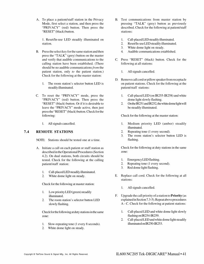
IL600 NC205 Tek-DIGICARE® Manual • 41Copyright © TekTone Sound & Signal Mfg., Inc. All Rights Reserved.
A. To place a patient/staff station in the PrivacyMode, first select a station, and then press the“PRIVACY” (red) button. Then press the“RESET” (black) button.
1. Reset/In-use LED steadily illuminated onstation.
B. Press the select key for the same station and thenpress the “TALK” (grey) button on the masterand verify that audible communications to thecalling station have been established. (Thereshould be no audible communications from thepatient station, only to the patient station.)Check for the following at the master station:
1. The room station’s selector button LED issteadily illuminated.
C. To reset the “PRIVACY” mode, press the“PRIVACY” (red) button. Then press the“RESET” (black) button. Or if it is desirable toleave the “PRIVACY” mode active, then justpress the “RESET” (black) button. Check for thefollowing:
1. All signals cancelled.
7.4 REMOTE STATIONS
NOTE: Stations should be tested one at a time.
A. Initiate a call on each patient or staff station asdescribed in the Operational Procedures (Section4.2). On dual stations, both circuits should betested. Check for the following at the callingpatient/staff station:
1. Call-placed LED steadily illuminated.2. White dome light on steady.
Check for the following at master station:
1. Low priority LED (green) steadilyilluminated.
2. The room station’s selector button LEDslowly flashing.
Check for the following at duty stations in the samezone:
1. Slow-repeating tone (1 every 8 seconds).2. White dome light on steady.
B. Test communications from master station bypressing “TALK” (grey) button as previouslydescribed. Check for the following at patient/staffstations:
1. Call-placed LED steadily illuminated.2. Reset/In-use LED steadily illuminated.3. White dome light on steady.4. Audible communications established.
C. Press “RESET” (black) button. Check for thefollowing at all stations:
1. All signals cancelled.
D. Remove call cord or pillow speaker from receptacleon patient stations. Check for the following at thepatient/staff stations:
1. Call-placed LED (on IR255-IR258) and whitedome light slowly flashing.
2. On the IR251 and IR252, the white dome light willbe steadily illuminated.
Check for the following at the master station:
1. Medium priority LED (amber) steadilyilluminated.
2. Repeating tone (1 every second).3. The room station’s selector button LED is
flashing.
Check for the following at duty stations in the samezone:
1. Emergency LED flashing.2. Repeating tone (1 every second).3. Red dome light flashing.
E. Replace call cord. Check for the following at allstations:
1. All signals cancelled.
F. Upgrade the call priority of a station to Priority (asexplained in Section 7.3-5). Repeat above proceduresA - C. Check for the following at patient stations:
1. Call-placed LED and white dome light slowlyflashing on IR254-IR259.
2. Call-placed LED and white dome light steadilyilluminated on IR250-IR253.
42 • IL600 NC205 Tek-DIGICARE® Manual Copyright © TekTone Sound & Signal Mfg., Inc. All Rights Reserved.
Check for the following at master station:
1. Medium priority (amber) LED steadilyilluminated.
2. Repeating tone (1 every second).3. The room station’s selector button LED is
flashing.
Check for the following at a duty station in thesame zone:1. Emergency LED flashing.2. Repeating tone (1 every second).3. Red dome light slowly flashing.
G. Reset call at the patient station. Check for thefollowing at all stations:
1. All signals cancelled.
H. Upgrade the call priority of the station back toRoutine (as explained in Section 7.3-5).
NOTE: Calls may be placed from IR260A DutyStations in the same manner as described above.
7.5 SF SERIES PERIPHERAL DEVICES
SF Series peripheral devices should be tested one ata time.
A. Initiate a call on each visual station (one at a time)as described in the Operational Procedures(Section 4.3). Check for the following at visualstation:
1. Call-placed LED steadily illuminated.
Check for following at master station:
1. The room station’s selector button LED isflashing.
2. Low priority LED (green) steadily illuminated.3. Tone signal repeating (1 every 8 seconds).
Check for following at duty station in the samezone:
1. Call-placed LED steadily illuminated.2. Tone signal repeating (1 every 8 seconds).3. White dome light steadily illuminated.
B. Reset each visual station as described in theOperational Procedures (Section 4.3). Check forthe following at emergency, patient, duty, andmaster stations:
1. All signals cancelled.
C. Initiate a call on each emergency station (one ata time) as described in the Operational Procedures(Section 4.3). Check for the following atemergency station:
1. Call-placed LED flashing.
Check for following at associated patient station:
1. Red dome light flashing.
Check for following at master station:
1. The room station’s selector button LED isflashing.
2. Medium priority LED (amber) steadilyilluminated.
3. Tone signal repeating (1 every second).
Check for following at duty station in the samezone:
1. Emergency LED flashing.2. Tone signal repeating (1 every second).3. Red dome light flashing.
D. Reset each emergency station as described inthe Operational Procedures (Section 4.3). Checkfor the following at emergency, patient, duty,and master stations:
1. All signals cancelled.
E. Initiate a call on each code station (one at a time)as described in the Operational Procedures(Section 4.3). Check for the following at codecall:
1. Call-placed LED rapidly flashing.
Check for the following at associated patientstations:
1. Call-placed LED rapidly flashing.2. Blue dome light rapidly flashing.
Check for the following at master station:
1. Room station’s selector button LED isilluminated.
2. High priority LED (red) illuminated3. Tone signal repeating rapidly.
IL600 NC205 Tek-DIGICARE® Manual • 43Copyright © TekTone Sound & Signal Mfg., Inc. All Rights Reserved.
Check for the following at a duty station in thesame zone:
1. Emergency LED rapidly flashing.2. Tone signal repeating rapidly.3. Blue dome light rapidly flashing.
F. Reset each code call and check for the followingat code, patient, duty and master stations:
1. All signals cancelled.
G. If fire/smoke detector 2 contacts are used in placeof code stations, they may be tested in the samemanner as code stations. NOTE: High priorityLED (red) on master station will flash rapidly.All other indications remain the same except reddome flashing on duty station.
H. Register staff presence on each presence stationas described in the Operational Procedures(Section 4.3). Check for the following at presencestations:
1. Staff LED (green) steadily illuminated.
Check for the following at associated patientstations:
1. Green dome light steadily illuminated.
Check for the following at a duty station in thesame zone:
1. Green dome light steadily illuminated.
I. Cancel staff registration as described in theOperational Procedures (Section 4.3). Check forthe following at presence, patient, and duty station:
1. All signals cancelled.
7.6 LI SERIES PERIPHERAL DEVICES
A. To set LI Series Dome Lights, individuallyplace calls at a patient station (Sections 4.2 and 4.3)that reflect the dome light’s signals. For example:
1. To test the blue lamp, place a code call.2. To test the red lamp, place an emergency call.3. To test the white lamp, place a routine call.4. To test the green lamp, register a staff
presence.

44 • IL600 NC205 Tek-DIGICARE® Manual Copyright © TekTone Sound & Signal Mfg., Inc. All Rights Reserved.
APPENDIX 1.0 NC260B COMMUNICATIONS MODE
The following section provides detailed operation for thelocal mode.
A. Connect the prepared null modem cable (Refer toFigure 24) between the appropriate serial port onthe PC or laptop computer and connector J-13 onthe NC260B motherboard, then turn on S1-5 and S1-7 (Refer to Figure 26).
B. Turn on the NC205 system and the PC or laptop andexecute the desired terminal emulator program.
C. After the NC260B system has completed itsinitialization and has begun its normal scan cycle(activity LED’s on the selector cards will be blinkingand the fault LED’s will not be on), then place switchS1-3 on the NC260B motherboard to ON and thenOFF. The microprocessor on the NC260B shouldstop its normal operation and automatically transferto the communications mode. Verification that thesystem has changed modes will be evident in thatthe LED’s on the selector cards will not be blinkingand a Help/Menu screen will be presented on thePC/laptop computer. The NC205 system will remainin this mode unless one of the following itemsoccurs:
1. A “Leave Communications” command isissued from the PC/laptop computer.
2. An automatic “Time Out” occurs due tosystem inactivity. (Approximately 2-3minutes.)
3. A system reset to the NC260B is initiated.
1.3 REMOTE OPERATION
To use the NC260B communications mode from a remotelocation, the following items are required:
A. SITE REQUIREMENTS
1. An operating NC205 system with theNC260B and software installed.
2. An external modem attached to connectorJ-13 on the NC260B motherboard.
3. A standard commercial phone line attachedto the modem.
B. REMOTE REQUIREMENTS
1. A PC or laptop computer equipped with amodem capable of operating at 9600 baud.
Reference Section 1.4 CommunicationSoftware for terminal software opera-tion and settings.
2. A standard commercial phone line attachedto the modem.
1.1 GENERAL
The NC260B supports bidirectional communications betweenthe Central Equipment and an external communicationsmodem. The connection of the modem to the CentralEquipment is accomplished through the use of a built-in RS232port on the Central Equipment. This RS232 port is the sameport that was normally used to support pager and printeroperation with the NC260A with the PM263 attached serialport card.
Two additional system features are now accomplishedthrough the use of this port. They are:
A. The ability to program custom room labels, andB. The ability to accomplish limited system fault
location.
The utilization of the new features can be accomplished bothlocally (at the site) or remotely (from a location other than thesite).
Note: If no modem or laptop PC is connected to the serial portor if cable connection to the serial port is incorrect, the systemwill flash LED “D1” seven times at approximately one flashper half second. If this occurs, the port will be disabled forthis type of usage until the system is reset again.
When removing devices connected to the serial port, thesystem must be powered down prior to removal.
1.2 LOCAL OPERATION
To use the NC260B communications mode locally, the followingitems are required:
A. A PC or laptop computer, andB. A properly prepared null modem cable.
(Refer to Figure 24)
Reference Section 1.4 COMMUNICATION SOFTWARE forterminal software operation and settings.
2 3 4 5 7 8
2 3 4 5 7 8
TX RX RTS CTS
DCD GND
2 3 4 5 7 8
2 3 4
5 7
8
TX RX RTS CTS
DCD GND
Computer PC or Laptop To
Computer PC or Laptop To
DB25
DB9
Figure 24
OR
DB25
DB25
NC260B
NC260B
J13
J13

IL600 NC205 Tek-DIGICARE® Manual • 45Copyright © TekTone Sound & Signal Mfg., Inc. All Rights Reserved.
3. A standard RS232 serial cable. (DO NOTUSE A NULL MODEM CABLE FOR THISAPPLICATION.)Save the terminal mode settings as default.
The following section provides detailed operation for theremote mode.
A. SITE PREPARATION
1. Turn the NC205 system and modem off.2. Connect one end of the RS232 serial cable
to J-13 on the NC260B motherboard.3. Connect the other end of the RS232 serial
cable to the modem connector.4. Connect the phone line to the modem.5. Turn the NC205 system on.6. Turn the modem on.7. Turn on S1-5 and verify that S1-7 is OFF.
(Refer to Figure 26.)8. Place switch S1-3 ON.9. Place switch S1-3 OFF.10. The system is now ready for connection
to a remote computer via of the phone line.
B. REMOTE LOCATION PREPARATION
1. Turn on the PC or laptop computer andthe modem (if external).
2. Verify that a standard commercial phoneline is attached to the modem.
3. Enter into the terminal emulation programand verify that the following protocol isset:
a. Data Bits – 8b. Parity – Nonec. Stop Bit – 1
4. Dial the telephone number that is con-nected to the NC260B at the site.
5. Upon receipt of the incoming call, theNC260B will answer on the first ring andacknowledge the answer by displaying aHELP screen on the PC or laptop computer.At this point, bidirectional communica-tions are available between the NC260BCentral Equipment and the host computer.
6. After the session is completed, the hostcomputer operator will issue a “Leave Com-munications” command. This commandwill cause the site modem to disconnectfrom the NC260B.
1.4 COMMUNICATION SOFTWARE
There are many software programs that will provide theprotocols necessary to accomplish communication with theNC260B. Since most computer operating systems are eitherWindows 95 or Windows 98, the following section providesthe necessary guidance for using Windows suppliedHyperTerminal.
1. From Windows start HyperTerminal.2. When prompted, supply the connection name.3. Configure the communications port as follows:
a. Data Bits – 8b. Parity – Nonec. Stop Bit – 1d. Flow Control – None
4. Click OK.5. Select File.6. Select Properties.7. Select Settings.8. Set Emulation to ANSI.9. Set Backscroll buffer to 0.10. Select ASCII setup.
Make sure that only the two following boxes are selected:
A. Append line feeds to incoming line ends.B. Wrap lines that exceed terminal width. Line delay=0.
Character delay=0.

46 • IL600 NC205 Tek-DIGICARE® Manual Copyright © TekTone Sound & Signal Mfg., Inc. All Rights Reserved.
2.1 GENERAL
The communications feature available on the NC260B isintended to be utilized by technicians familiar with theoperation of the NC205 system. All of the user commandsare two characters in length and are text-based.
The general operation in this mode is for the user to enter thedesired two-character command at the prompt, followed by acarriage return. If no subsequent parameters are required, thecentral equipment processor will execute the function. At thecompletion of the task, the processor will issue a new commandprompt. If user supplied parameters, such as room labels,etc., are required, the central equipment processor will issuea parameter prompt (Par->) once the command has beenentered. The user must then supply the correctly formattedparameter(s), followed by a carriage return.
In communications mode, the first screen that will be seen ona PC or laptop computer connected to the NC260B is theHELP screen. The HELP screen is designed to provide theuser with a list of user commands that can be used to readand write data between the NC260B and the PC or laptopcomputer. Figure 25 depicts what the HELP screen lookslike.
Figure 25
The two-letter command code shown in the COMMANDScolumn can be used to perform the listed communicationsroutines between the NC260B and the PC or laptop computer.As an example, if the following key sequence were entered:DH <Enter>, the HELP screen would be displayed on theattached PC or laptop computer. A brief description for eachof the COMMANDS shown on the HELP page follows:
A. CS – Clears a simulated system call. (See SC)
B. CV – Displays the voltage on the selected call line.
C. DH – Displays the HELP screen.(Refer to Figure 25)
D. ID – Displays the copyright information for theCentral Equipment code as well as the versionidentifier of the installed code.
F. EC – Toggles the character echo function on andoff.
G. LI – This command allows the user to review thesoftware license.
H. LC – Used to terminate the communications modeand restore NC260B system to the normal scan mode.
I. LF – Toggles the line feed issued by the NC260BON and OFF.
J. MR – Allows the NC260B processor to return to itsnormal scan cycle with the capability of being placedback into the communications mode with a singlekey press (space bar). If any event occurs while thesystem is operating in the monitor mode, the statusof the event will be displayed at the host computerinstead of on the normally attached printer.
K. PD – This command will cause the NC260B to stepthrough all specified zones and measure the selectline voltages. These voltage measurements are madewith the select line high and low. If any line fails toindicate the correct voltage, an error will be loggedon the PC or laptop computer screen for the failedroom. When PD is selected, the user is promptedwith two questions. The explanation of thesequestions is as follows:
1. MAP? (Y or N) –a. If the operator selects Y, the system will
scan all of the zones that the system foundduring its initial scan.
b. If the operator selects N, the system willonly scan the zone specified by the user.
2. STEP? (Y or N) –a. If the operator selects Y, the system will
automatically step through each room oneach zone that the system found during itsinitial scan.
b. If the operator selects N, the operator willbe able to press any key to step from oneroom to the next.
L. RC –This command reads and displays the pagercap code assigned to a room. A typical entry forthis routine would be:
a. RL <ENTER>b. PAR-> 001,064 <ENTER>
(Where 001 is the starting room numberand 064 is the ending room number.)
COMMANDS PARAMETERS DESCRIPTION
CS NONE CLEAR SIM CALLSCV ### POINT VOLTAGEDH NONE DISPLAY HELPDZ NONE READ ZONE C CODESEC NONE TOGGLE ECHOID NONE DISPLAY IDLC NONE LEAVE COMMLI NONE LICENSELF NONE TOGGLE LFMR NONE MONITORPD 1, 2, 3, ... DIAGNOSTICRC ###, ### READ STTN C CODERL ###, ### READ LABELSC ###, P SIMULATE CALLS P D, S, P SET PROTOCOLWC ###, CCCC WRITE CODEWL ###, CCCCCCCC WRITE LABEL
APPENDIX 2.0 SYSTEM OPERATION

IL600 NC205 Tek-DIGICARE® Manual • 47Copyright © TekTone Sound & Signal Mfg., Inc. All Rights Reserved.
M. RL – This command reads and displays the labelassigned to a zone/room and displays the data onthe host PC or laptop computer. A typical entry forthis routine would be:
a. RL <Enter>b. RRR, QQQ or 101, 005 <Enter> (RRR is the
starting room number and QQQis thequantity of rooms to read.)
N. SC – This command allows a simulated call to beplaced to the Master without actually placing a callfrom the field. The type of call is selectable. Theproper entry for this command is:
a. SC<Enter>b. PAR->###, X <Enter>
(###=Point Number)(X= Priority Code, Fire, Emergencyor Routine)
O. SP–This command is used to set thecommunications protocol that the NC260B uses tocommunicate with the PC or laptop computer. Thisprotocol will be applied upon the next system reset,provided S1-5 and S1-6 are set to the “ON” positionon the NC260B. If S1-5 is the only switch on theNC260B that is set then the protocol will default to8,1,N. (i.e. at P> prompt, enter 71E which would resultin 7 data bits, 1 stop bit and parity enabled).
P. WC– This command is used to assign pager capcodes to either room ID’s or zones.Note: The default mode is for all calls to be pagedby call type, I.E. all routine calls will go to 401a, allemergency calls will go to 400c and all code callswill go to 400d. The default mode will be disabled ifthe WC command is used to set cap codes. Resetswill be always sent to cap code 402a, regardless ofthe mode used. When WC is selected the operatoris prompted as follows:
1. Setup page by room? (Y or N)a. If the operator selects Y the system
will display the parameter (PAR->)prompt. A typical entry here wouldbe: PAR-> 001,406a <ENTER> Thiswould set selector point number 1 topage to cap code 406a. After <EN-TER> is pressed the next point will bedisplayed, continue programming orpress <ENTER>to be returned to thecommand prompt.
S5 S6 ProtocolOff Off 8, 1, 0On Off 8, 1, NOn On Look in EEPROM*
*If protocol has NOT been set on previous bi-directionalsession, the protocol defaults to 8, 1, N.
b. If the operator selects N, the message“Setup Page By Zone?” Will be dis-played. A typical entry here would be:PAR-> 002,402b <ENTER> This wouldset zone number 2 to page to cap code402b. Note: Any selectors which have
Figure 26ON
OFF
1 2 3 4 5 6 7
1 - Learn Mode Switch2 - Memory Lock
3 - Start Bi-Directional Mode4 - Reset
5 - Protocol6 - Protocol
7 - No Modem
been programmed through the “SetupPage By Room” menu will page to thecap code they were assigned to, re-gardless of how the zones are as-signed.
Q. WL– This command allows the user to write labelsto any room attached to the NC260B system. Thelabels are limited in length to eight (8) characters.The proper entry for this command is:
a. WL <Enter>b. ###,CCCCCCCC (Where ### is the room
number and CCCCCCCCis the desired la-bel for that room).
This function overwrites any previously as-signed label, including default labels. Whenfinished entering the desired labels and roomnumbers, the user exists this routine by de-pressing the ENTER key.

48 • IL600 NC205 Tek-DIGICARE® Manual Copyright © TekTone Sound & Signal Mfg., Inc. All Rights Reserved.
NOTE:The following information will be sent to the cap code 402A,regardless of how the system is programmed. This is done sothat if an event printer is connected to the serial port, thisinformation will still be printed. Do not use cap code 402A forpagers, unless you desire resets, ETC to appear on pagers.
COMM FAULT - Communication Fault
CODE FAULT - Code Fault
STAF FLLW ON - Staff Follow ON
ROOM FLLW ON - Room Follow ON
PAGE BEGIN - Page Begin
TALK INITIATE - Talk Initiate
PROG MODE ON - Program Mode ON
ROUTINE RESET - Routine Reset
EMRGNCY RESET - Emergency Reset
CODE RESET - Code Reset
FIRE CLEARED - Fire Cleared
PRS ATT RESET - Personal Attention Reset
FAULT CLEARED - Fault Cleared
STAF REQ RSET - Staff Request Reset
STAFF OUT - Staff Out
STAF FLLOW OFF - Staff Follow OFF
ROOM FLLW OFF - Room Follow OFF
PAGE END - Page End
TALK TRMINATE - Talk Terminate
PROG MODE OFF - Program Mode OFF
PAG STAF BEGN - Page Staff Begin
2.2 ERROR CODES AND MESSAGES
Typographical errors, entering the incorrect data, and systemfaults can cause certain error codes and messages to appearon the PC or laptop computer. The following error codesand explanations are typical:
ERROR CODE EXPLANATION
ER1 Command entered is not recognized
ER2 The parameters that were entered are not inthe proper format or are otherwise invalid.
ER3 The processor has timed out of thecommunications mode. (NOTE: Prior totiming out, fault LEDs D1-D3 will begin tocycle. A key press at this point will avert thetime out routine.)
ER4 During diagnostic testing, a select line wasnot at least mid-scale (~6v) when notselected.
ER5 During diagnostic testing, a select line couldnot be pulled down near ground potential.
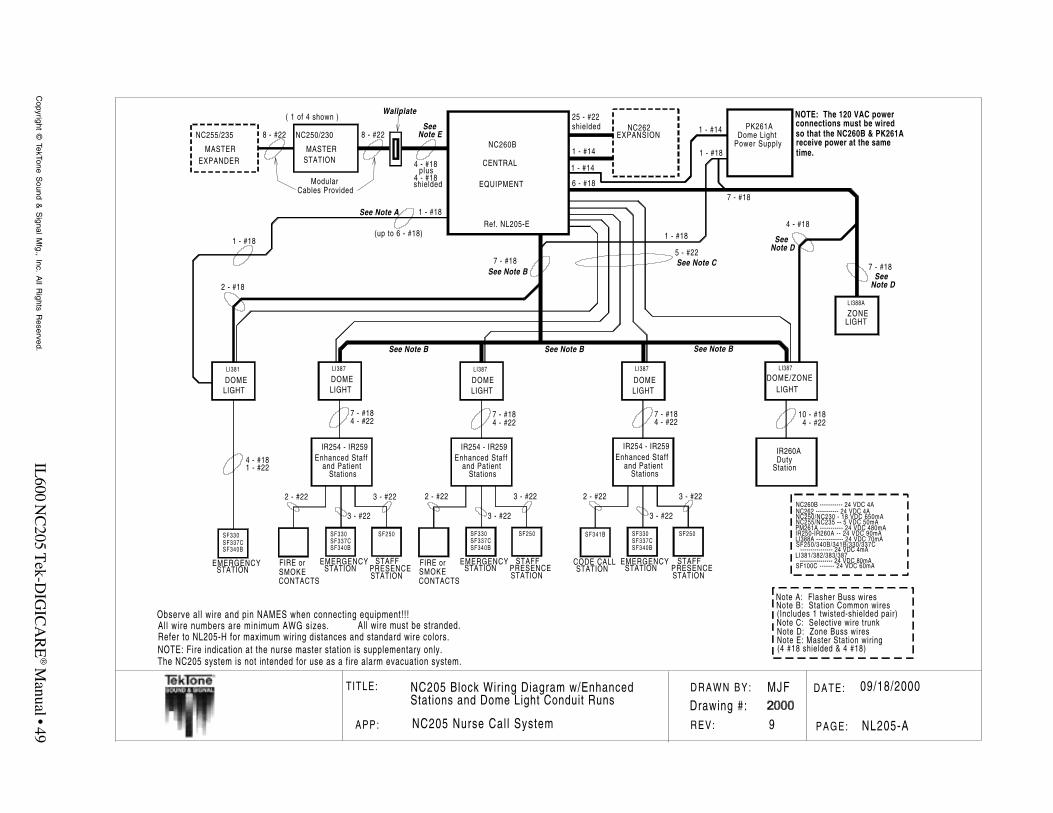
IL600 N
C205 T
ek-DIG
ICA
RE
® Manual • 49
Copyright ©
TekTone Sound &
Signal M
fg., Inc. All R
ights Reserved.
T ITLE: DATE:D R A W N B Y :
REV: PAGE:APP:
09/18/2000
NL205-A
MJF
9NC205 Nurse Cal l System
EMERGENCY
SF330
STATIONSTAFF
SF250
STATIONPRESENCE
SF337CSF340B
DOME/ZONE
EMERGENCY
IR254 - IR259
SF330
STATIONCODE CALL
SF341B
STATIONSTAFF
SF250
STATIONPRESENCE
SF337CSF340B
CONTACTS
DutyIR260A
Station
EMERGENCY
SF330
STATION
SF337CSF340B
ZONELI388A
LIGHT
LI387
LIGHT
NC260B
CENTRAL
EQUIPMENT
NC262EXPANSION
MASTERSTATION
NC250/230
MASTEREXPANDER
NC255/235
( 1 of 4 shown )
SMOKE
DOMELI387
LIGHTDOMELI387
LIGHTDOMELI387
LIGHTDOMELI381
LIGHT
7 - #18
6 - #18
5 - #22
8 - #22
7 - #18
4 - #18
1 - #18
FIRE or
1 - #14
1 - #18
4 - #18
7 - #184 - #22
7 - #184 - #22
3 - #22
3 - #222 - #22
7 - #184 - #22
2 - #22 3 - #22
3 - #22
10 - #184 - #22
2 - #18
1 - #22
25 - #22shielded
8 - #22
Wallplate
Cables Provided
See Note CSee Note B
See Note A
Note D
Note E
See
(up to 6 - #18)
Modular
See
See Note B
Note DSee
See Note BSee Note B
Note A: Flasher Buss wiresNote B: Station Common wires(Includes 1 twisted-shielded pair)
Note D: Zone Buss wiresNote C: Selective wire trunk
Note E: Master Station wiring(4 #18 shielded & 4 #18)
NC260B ----------- 24 VDC 4ANC262 ----------- 24 VDC 4ANC250/NC230 - 18 VDC 650mANC255/NC235 -- 5 VDC 50mAPM261A ----------- 24 VDC 480mAIR250-IR260A -- 24 VDC 90mALI388A ------------- 24 VDC 70mASF250/340B/341B/330/337C
---------------- 24 VDC 4mALI381/382/383/387
---------------- 24 VDC 80mASF100C ------- 24 VDC 60mAEMERGENCY
SF330
STATIONSTAFF
SF250
STATIONPRESENCE
SF337CSF340B
CONTACTSSMOKEFIRE or
3 - #22
3 - #222 - #22
PK261ADome Light
Power Supply
1 - #14
1 - #14
1 - #18
1 - #18
NOTE: The 120 VAC powerconnections must be wiredso that the NC260B & PK261Areceive power at the sametime.
NC205 Block Wiring Diagram w/EnhancedStations and Dome Light Conduit Runs
Enhanced Staffand Patient
Stations
IR254 - IR259Enhanced Staff
and PatientStations
IR254 - IR259Enhanced Staff
and PatientStations
Refer to NL205-H for maximum wiring distances and standard wire colors.All wire numbers are minimum AWG sizes.Observe all wire and pin NAMES when connecting equipment!!!
All wire must be stranded.
NOTE: Fire indication at the nurse master station is supplementary only.The NC205 system is not intended for use as a fire alarm evacuation system.
7 - #18
4 - #18
4 - #18shielded
plus
Ref. NL205-E
Drawing #:
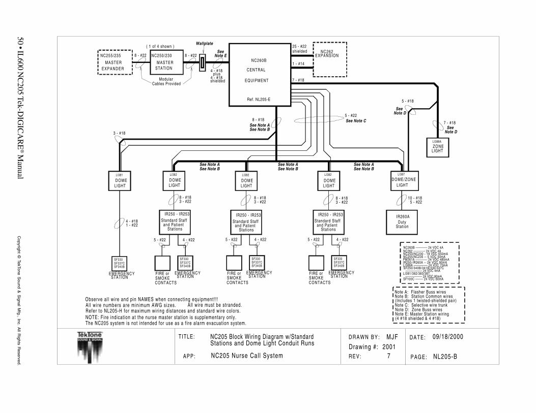
50 • IL600 N
C205 Tek-D
IGIC
AR
E® M
anualC
opyright © TekTone S
ound & S
ignal Mfg., Inc. A
ll Rights R
eserved.
T ITLE: DATE:D R A W N B Y :
REV: PAGE:APP:
09/18/2000
NL205-B
MJF
7NC205 Nurse Cal l System
CONTACTS
DOME/ZONE
IR260A
EMERGENCY
SF330
STATION
SF337CSF340B
ZONELI388A
LIGHT
LI387
LIGHT
NC260B
CENTRAL
EQUIPMENT
NC262EXPANSION
MASTERSTATION
NC250/230
MASTERE X P A N D E R
NC255/235
( 1 of 4 shown )
S M O K EEMERGENCY
SF330
STATION
SF337CSF340B
IR250 - IR253
D O M ELI382
LIGHTD O M ELI382
LIGHTD O M ELI382
LIGHTD O M ELI381
LIGHT
FIRE or
8 - #18
7 - #18
5 - #22
8 - #22
7 - #18
5 - #18
1 - #14
4 - #18
8 - #18
5 - #22 4 - #22
3 - #2210 - #18
5 - #22
3 - #18
1 - #22
25 - #22shielded
8 - #22
Wallplate
Cables Provided
See Note C
See Note BSee Note A
Note D
Note E
See
Modular
See
Note DSee
Note A: Flasher Buss wiresNote B: Station Common wires(Includes 1 twisted-shielded pair)
Note D: Zone Buss wiresNote C: Selective wire trunk
Note E: Master Station wiring(4 #18 shielded & 4 #18)
NC260B ----------- 24 VDC 4ANC262 ----------- 24 VDC 4ANC250/NC230 - 18 VDC 650mANC255/NC235 -- 5 VDC 50mAPM261A ----------- 24 VDC 480mAIR250-IR260A -- 24 VDC 90mALI388A ------------- 24 VDC 70mASF250/340B/341B/330/337C
---------------- 24 VDC 4mALI381/382/383/387
---------------- 24 VDC 80mASF100C ------- 24 VDC 60mA
CONTACTSS M O K E
EMERGENCY
SF330
STATION
SF337CSF340B
FIRE or
5 - #22 4 - #22
CONTACTSS M O K E
EMERGENCY
SF330
STATION
SF337CSF340B
FIRE or
5 - #22 4 - #22
8 - #183 - #22
8 - #183 - #22
See Note BSee Note A
See Note BSee Note A
See Note BSee Note A
NC205 Block Wiring Diagram w/StandardStations and Dome Light Conduit Runs
DutyStat ion
Standard Staffand Patient
Stat ions
IR250 - IR253Standard Staff
and PatientStat ions
IR250 - IR253Standard Staff
and PatientStat ions
Refer to NL205-H for maximum wir ing distances and standard wire colors.A l l w i re numbers are min imum AWG sizes.Observe al l wire and pin NAMES when connect ing equipment! ! !
Al l wire must be stranded.
NOTE: Fire indicat ion at the nurse master stat ion is supplementary only.The NC205 system is not intended for use as a f ire alarm evacuat ion system.
4 - #18
4 - #18shielded
plus
Ref. NL205-E
Drawing #: 2001

IL600 N
C205 T
ek-DIG
ICA
RE
® Manual • 51
Copyright ©
TekTone Sound &
Signal M
fg., Inc. All R
ights Reserved.
T ITLE: DATE:D R A W N B Y :
REV: PAGE:APP:
09/18/2000
NL205-C
MJF
8NC205 Nurse Cal l System
EMERGENCY
SF330
STATIONSTAFF
SF250
STATIONPRESENCE
SF337CSF340B
DOME/ZONE
EMERGENCY
IR254 - IR259
SF330
STATIONCODE CALL
SF341B
STATIONSTAFF
SF250
STATIONPRESENCE
SF337CSF340B
CONTACTS
IR260A
EMERGENCY
SF330
STATION
SF337CSF340B
ZONELI388A
LIGHT
LI387
LIGHT
NC260B
CENTRAL
EQUIPMENT
NC262EXPANSION
MASTERSTATION
NC250/230
MASTEREXPANDER
NC255/235
( 1 of 4 shown )
SMOKE
DOMELI387
LIGHTDOMELI387
LIGHTDOMELI387
LIGHTDOMELI381
LIGHT
7 - #18
6 - #18
5 - #22
8 - #22
7 - #18
4 - #18
1 - #18
FIRE or
1 - #14
1 - #18
4 - #22 4 - #22
3 - #22
3 - #222 - #22
4 - #22
2 - #22 3 - #22
3 - #22
4 - #185 - #22
2 - #18
2 - #22
25 - #22shielded
8 - #22
Wallplate
Cables Provided
See Note CSee Note B
See Note A
Note D
Note E
See
(up to 6 - #18)
Modular
See
Note DSee
See Note B
Note A: Flasher Buss wiresNote B: Station Common wires(Includes 1 twisted-shielded pair)
Note D: Zone Buss wiresNote C: Selective wire trunk
Note E: Master Station wiring(4 #18 shielded & 4 #18)
NC260B ----------- 24 VDC 4ANC262 ----------- 24 VDC 4ANC250/NC230 - 18 VDC 650mANC255/NC235 -- 5 VDC 50mAPM261A ----------- 24 VDC 480mAIR250-IR260A -- 24 VDC 90mALI388A ------------- 24 VDC 70mASF250/340B/341B/330/337C
---------------- 24 VDC 4mALI381/382/383/387
---------------- 24 VDC 80mASF100C ------- 24 VDC 60mA
EMERGENCY
SF330
STATIONSTAFF
SF250
STATIONPRESENCE
SF337CSF340B
CONTACTSSMOKEFIRE or
3 - #22
3 - #222 - #22
PK261ADome Light
Power Supply
1 - #14
1 - #14
1 - #18
1 - #18
See Note BSee Note B
NOTE: The 120 VAC powerconnections must be wiredso that the NC260B & PK261Areceive power at the sametime.
NC205 Block Wir ing Diagram w/EnhancedStations and Conduit Runs to Stations
DutyStation
Enhanced Staffand Patient
Stations
IR254 - IR259
Enhanced Staffand Patient
Stations
IR254 - IR259
Enhanced Staffand Patient
Stations
Refer to NL205-H for maximum wiring distances and standard wire colors.All wire numbers are minimum AWG sizes.Observe all wire and pin NAMES when connecting equipment!!!
All wire must be stranded.
NOTE: Fire indication at the nurse master station is supplementary only.The NC205 system is not intended for use as a fire alarm evacuation system.
7 - #18
Ref. NL205-E
4 - #18
4 - #18shielded
plus
Drawing #: 2002

52 • IL600 N
C205 Tek-D
IGIC
AR
E® M
anualC
opyright © TekTone S
ound & S
ignal Mfg., Inc. A
ll Rights R
eserved.
T ITLE: DATE:D R A W N B Y :
REV: PAGE:APP:
09/18/2000
NL205-D
MJF
7NC205 Nurse Cal l System
CONTACTS
DOME/ZONE
EMERGENCY
SF330
STATION
SF337CSF340B
ZONELI388A
LIGHT
LI387
LIGHT
CENTRAL
EQUIPMENT
NC262EXPANSION
MASTERSTATION
NC250/230
MASTEREXPANDER
NC255/235
( 1 of 4 shown )
SMOKEEMERGENCY
SF330
STATION
SF337CSF340B
DOMELI382
LIGHTDOMELI382
LIGHTDOMELI382
LIGHTDOMELI381
LIGHT
FIRE or
8 - #18
7 - #18
5 - #22
8 - #22
7 - #18
5 - #18
1 - #14
5 - #22 4 - #22
3 - #22 5 - #22
3 - #18
2 - #22
25 - #22shielded
8 - #22
Wallplate
Cables Provided
See Note C
See Note BSee Note A
Note D
Note E
See
Modular
See
Note DSee
Note A: Flasher Buss wiresNote B: Station Common wires(Includes 1 twisted-shielded pair)
Note D: Zone Buss wiresNote C: Selective wire trunk
Note E: Master Station wiring(4 #18 shielded & 4 #18)
NC262 ----------- 24 VDC 4ANC250/NC230 - 18 VDC 650mANC255/NC235 -- 5 VDC 50mAPM261A ----------- 24 VDC 480mAIR250-IR260A -- 24 VDC 90mALI388A ------------- 24 VDC 70mASF250/340B/341B/330/337C
---------------- 24 VDC 4mALI381/382/383/387
---------------- 24 VDC 80mASF100C ------- 24 VDC 60mA
CONTACTSSMOKE
EMERGENCY
SF330
STATION
SF337CSF340B
FIRE or
5 - #22 4 - #22
CONTACTSSMOKE
EMERGENCY
SF330
STATION
SF337CSF340B
FIRE or
5 - #22 4 - #22
3 - #22 3 - #224 - #18
See Note BSee Note A
See Note BSee Note A
See Note BSee Note A
NC205 Block Wir ing Diagram w/StandardStations and Conduit Runs to Stations
IR250 - IR253Standard Staff
and PatientStations
IR250 - IR253Standard Staff
and PatientStations
IR250 - IR253Standard Staff
and PatientStations
IR260ADuty
Station
NC260B ----------- 24 VDC 4A
NC260B
Refer to NL205-H for maximum wiring distances and standard wire colors.All wire numbers are minimum AWG sizes.Observe all wire and pin NAMES when connecting equipment!!!
All wire must be stranded.
NOTE: Fire indication at the nurse master station is supplementary only.The NC205 system is not intended for use as a fire alarm evacuation system.
4 - #18
4 - #18shielded
plus
Ref. NL205-E
Drawing #: 2003

IL600 N
C205 T
ek-DIG
ICA
RE
® Manual • 53
Copyright ©
TekTone Sound &
Signal M
fg., Inc. All R
ights Reserved.
T ITLE: DATE:DRAWN BY:
REV: PAGE:APP:
11/3 /1999
NL205-E
M J F
13NC205 Nurse Cal l SystemDrawing #:
NC260B Cent ra l Equ ipment Wir ing
7 6 5 4 3 2 1
123456
123456
8 7 6 5 4 3 2 1
8 7 6 5 4 3 2 1
8 7 6 5 4 3 2 1
O R A N G ER E D
V I O L E TB R O W NG R E E N
B L U E
P M 2 6 1 A S e l e c t o r C a r d # 1 P M 2 6 1 A S e l e c t o r C a r d # 2
MASTER #1
MASTER #2
MASTER #3
MASTER #4
To Master Stat ions(4#18 shielded and 4#18per master station)
+18
VDC
Cont
rolI
n
Cont
rolO
ut
Faul
tDi
gita
lAud
ioIn
Digi
talA
udio
Out
Pow
erO
n
Syst
emG
roun
d
NC260B Central Equipment(PM260B)
AUDIO (+ )AUDIO ( - )S T A T I O N G R O U N DS T A T I O N P O W E RN U R S E ( C O N T R O L # 0 )P R I O R I T Y ( C O N T R O L # 1 )
SYSTEM POWER
4 PIN HEADER
BATTERY BACKUP(BA002K)
2 PIN HDR.
SERIAL DATA PORTD B 2 5 C O N N E C T O R
NOTE: Common connectors do notfollow standard color code, but areordered to match color to color withstat ion common connectors.
SELE
CTI
VEW
IRE
TRU
NKS
STATION COMMONS BUSS
1-
89
-16
17-
2425
-32
(1 Twisted Shielded Pr. #18 and 4#18)
NOTE: Common wires and Select ive wireconnected to an individual station mustcome from the same PM261A Selectorcard. DO NOT cross-connect f rom oneselector card to another.
NOTE: SELECTIVE GROUND WIRE. Run1 additional #22 selective (ground) wire(within selective wire trunk) per every 8selective wires. This wire should be conn-ected to the NC260B chassis ground lug.The other end of this conductor should becontinuous to the end of the selective wiretrunk run, which must be left floating andisolated.
123456
123456
Z O N E P O W E RZ O N E D A T A 0Z O N E D A T A 1Z O N E D A T A 2Z O N E S E L E C T
S Y S T E M G R O U N D
F L A S H E R P O W E RF A S T F L A S HF A S T F L A S H
S L O W F L A S HS L O W F L A S H
S Y S T E M G R O U N D
9#22
Z O N E B U S S F L A S H E R B U S S
Up to 6 - #18
DB
25C
ON
NE
CTO
R
Cen
tralE
quip
men
tEx
pans
ion
Port
To NC262A CE Expander(If used.)
25 #22 Shielded (CT261)
1
2PowerGround
This l ine is used for Zone Buss whenPK261A Dome Lamp Power Supply is notinstalled in system.
*** 16 zone l ight maximum***w i t h P K 2 6 1 A D o m e L a m p P o w e r S u p p l y
*** 8 zone l ight maximum***w i t h o u t P K 2 6 1 A D o m e L a m p P o w e r S u p p l y
re fe rence NL205-N fo r de ta i l s
NOTES:1. *ALL FIELD WIRING SHOULD BE TERMINATED OUTSIDE OF SYSTEM EQUIPMENT ENCLOSURES.*2. *8 patient station MAXIMUM per station common cable run.*3. Refer to NL205-H for maximum wiring distances and standard wire colors.4. Observe wire and pin NAMES when connect ing equipment!5. All wire numbers are minimum AWG sizes. All wire must be stranded.6. Audio shields should be connected to the NC260B Ground Lug. These shields should be continuous
unti l the end of the run, where they wil l be taped back and isolated. Any unused wires in the commoncables or in the select ive l ine trunk cables should be connected to the NC260B Ground Lug and havetheir f ield end isolated. If selective line cable has a shield, the shield should be conn-ected to the NC260B Ground Lug with its f ield end isolated.
STATION COMMONS BUSS
BROWNREDORANGEYELLOWGREENBLUEVIOLETGRAYWHITEBLACK
123456789
10
PIN# STANDARD WIRE COLOR
8
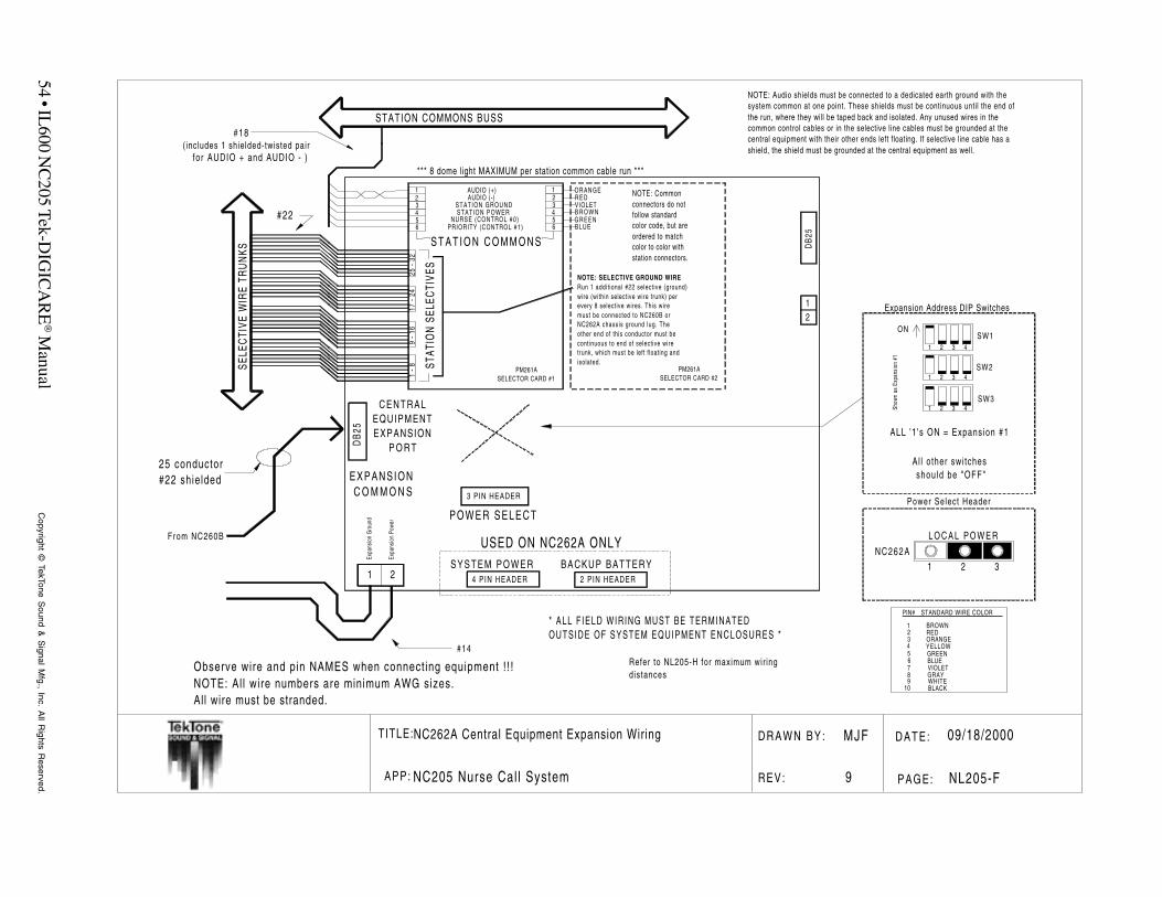
54 • IL600 N
C205 Tek-D
IGIC
AR
E® M
anualC
opyright © TekTone S
ound & S
ignal Mfg., Inc. A
ll Rights R
eserved.
T ITLE: DATE:D R A W N B Y :
REV: PAGE:APP:
09/18/2000
NL205-F
MJF
9NC205 Nurse Cal l System
NC262A Central Equipment Expansion Wiring
ORANGER E DVIOLETB R O W NG R E E NBLUE
S Y S T E M P O W E R4 PIN HEADER
BACKUP BATTERY2 PIN HEADER
SELE
CTI
VEW
IRE
TRU
NKS
STATION COMMONS BUSS
1-8
9-1
617
-24
25-3
2
( includes 1 shielded-twisted pair
DB
25
12
BROWNREDORANGEYELLOWGREENBLUEVIOLETGRAYWHITEBLACK
123456789
10
PIN# STANDARD WIRE COLOR
Observe wire and pin NAMES when connect ing equipment ! ! !NOTE: Al l wire numbers are minimum AWG sizes.All wire must be stranded.
Refer to NL205-H for maximum wir ingdistances
* ALL F IELD WIRING MUST BE TERMINATEDOUTSIDE OF SYSTEM EQUIPMENT ENCLOSURES *
NOTE: Audio shields must be connected to a dedicated earth ground with thesystem common at one point. These shields must be continuous until the end ofthe run, where they will be taped back and isolated. Any unused wires in thecommon control cables or in the selective line cables must be grounded at thecentral equipment with their other ends left floating. If selective line cable has ashield, the shield must be grounded at the central equipment as well.
#18
for AUDIO + and AUDIO - )*** 8 dome light MAXIMUM per station common cable run ***
123456
123456
AUDIO (+)AUDIO (-)
STATION GROUNDSTATION POWER
NURSE (CONTROL #0)PRIORITY (CONTROL #1)
S T A T I O N C O M M O N S
STAT
ION
SELE
CTI
VES
PM261ASELECTOR CARD #1
PM261ASELECTOR CARD #2
NOTE: Commonconnectors do notfollow standardcolor code, but areordered to matchcolor to color withstation connectors.
NOTE: SELECTIVE GROUND WIRERun 1 addit ional #22 selective (ground)wire (within selective wire trunk) perevery 8 selective wires. This wiremust be connected to NC260B orNC262A chassis ground lug. Theother end of this conductor must becontinuous to end of selective wiretrunk, which must be left f loating andisolated.
3 PIN HEADER
P O W E R S E L E C T
USED ON NC262A ONLY
DB
25
C E N T R A LEQUIPMENTEXPANSION
P O R T
1 2
Expa
nsio
nG
roun
d
Expa
nsio
nPo
wer
EXPANSIONC O M M O N S
#22
25 conductor#22 shielded
Power Select Header
NC262A1 2 3
L O C A L P O W E R
ALL '1 's ON = Expansion #1
Al l other swi tchesshould be "OFF"
Show
nas
Expa
nsio
n#1
SW1
SW2
SW3
ON
1 2 3 4
1 2 3 4
1 2 3 4
From NC260B
#14
Expansion Address DIP Switches

IL600 N
C205 T
ek-DIG
ICA
RE
® Manual • 55
Copyright ©
TekTone Sound &
Signal M
fg., Inc. All R
ights Reserved.
T ITLE:
APP:
NC250/NC230 Master Sta t ions &NC255 Master Stat ion Expander
NC205 Nurse Call System
DRAWN BY:
REV:
DATE:
PAGE:
MJF
11
6/4/2001
NL205-G
BROWNREDORANGEYELLOWGREENBLUEVIOLETGRAYWHITEBLACK
123456789
10
PIN# STANDARD WIRE COLOR
NOTE: All wire numbers are minimum AWG sizes.All wire must be stranded.Refer to NL205-H for maximum wiring distances and standard wire colors
Wall Plate (TekTone® Part #PL467)
1=+18VDC2=CONTROL IN3=POWER ON4=CONTROL OUT5=DIGITAL AUDIO IN6=FAULT7=DIGITAL AUDIO OUT8=SYSTEM GROUND
NOTE:Pins 1 (+18VDC), 5 (Digital Audio IN),7 (Digital Audio OUT), and 8 (SystemGround) are included in the shielded cable.
WHITE BLUE
BROWN ORANGE
YELLOW BLACK
GREEN RED
1
2
3
45
6
7
8
To Master #1
To Master #2
To Master #3
To Master #4
MASTER #4
MASTER #3
MASTER #2
MASTER #1
8 wires each
12345678
+18V
DCCO
NTRO
LIN
POW
ERO
NCO
NTRO
LOU
TDI
GITA
LAU
DIO
INFA
ULT
DIGI
TAL
AUDI
OOU
TSY
STEM
GROU
ND
4-#18 sh ie lded and 4-#18 per master s ta t ion .(See no te be low)
NC260B Central Equipment
*ALL
FIEL
DW
IRIN
GM
UST
BETE
RM
INAT
EDO
USI
DE
OF
SYST
EMEQ
UIP
MEN
TEN
CLO
SUR
ES*
8 conductor Modular cable (7' cableprovided each Master Station) witheach Master Station
Observe wire and pin NAMES when connect ing equipment ! ! !
NC255MASTER EXPANDER
NOTE:Addressing NC255 Master Expanders incorrectlywill result in damage to units upon power application.Check Figure 9 for correct dipswitch settings.
Modular jacks
Expander IN Expander OUT
To otherExpanders
1
2
3
4
5
6
7
8
8
7
6
5
4
3
2
1
(1.3' cable providedwith each MasterExpander)
8 conductorModular cable
1=+18VDC2=CONTROL IN3=POWER ON4=CONTROL OUT5=DIGITAL AUDIO IN6=FAULT7=DIGITAL AUDIO OUT8=SYSTEM GROUND
Modular jacks
Master IN Expander OUT8
7
6
5
4
3
2
1
8
7
6
5
4
3
2
1
NC250/230MASTER STATION

56 • IL600 NC205 Tek-DIGICARE® Manual Copyright © TekTone Sound & Signal Mfg., Inc. All Rights Reserved.
TITLE: Maximum Wiring Distances DRAWN BY: MJF DATE: 09/18/2000
and Standard Wire Colors
APP: NC205 Nurse Call System REV: 8 PAGE: NL205-H
®
PIN # STANDARD WIRE COLOR
1 Brown2 Red3 Orange4 Yellow5 Green6 Blue7 Violet (Purple)8 Gray9 White10 Black11 Brown/White12 Red/White13 Orange/White14 Yellow/White15 GreenWhite
NC260B NC262A NC250/230 NC255- Central Equipment- CE Expanders- Master Stations- Master Expanders
NC260B X 18´ TOTAL 250´ PER XDISTANCE MASTER
NC262A 18´ TOTAL X X XDISTANCE
NC250/230 250´ PER X X 10´ TOTALMASTER DISTANCE
NC255 X X 10´ TOTAL 2´DISTANCE
NC260B/262A IR Series SF Series LI388A ZoneStations Stations Light
- Central Equipment& Expanders
- IR & SF SeriesStations
- LI Series Lights
NC260B/262A X
SF Series 100´ X XStations
IR Series X 100’ XStations
1000´ TOTAL(4 runs at 250´ per cable
run of 8 stations)
500´ TOTAL(stand alone)
(per expander)
1000´ TOTAL(2 runs at 500´ per
cable run of 8 zone lights)
1000´ TOTAL(4 runs at 250´ per cable
run of 8 stations)
500’ TOTAL(stand alone)

IL600 NC205 Tek-DIGICARE® Manual • 57Copyright © TekTone Sound & Signal Mfg., Inc. All Rights Reserved.
TITL
E:
APP:
DR
AW
NB
Y:
REV
:
DA
TE:
PA
GE
:
NC260AUP TO 16 LI388A STATIONS
ZONE BUSS
SF SERIES STATIONS
LI SERIES LIGHTS
NC260A
STAND-ALONE CONFIGURATION
FLASHER BUS18 awg stranded up to 6 conductor
22 awg stranded selective line
18 awg stranded, up to 7 conductors
FAST FLASH
SLOW FLASHSF STATIONS AND LI LIGHTSMAY BE USED IN COMBINATION WITHIR SERIES STATIONS FOR A TOTAL OF 250IF STANDARD IR STATIONS ARE USED AND 128IF ENHANCED IR ARE USED
UP TO 500 '
UP TO 500 '
34pF/Ft., 5.9 ohms/1000' @ 25C maximum.
55pF/Ft., 14.7 ohms/1000' @ 25C maximum.
34pF/Ft., 5.9 ohms/1000' @ 25C maximum.
1000' maximum per zone connection.Eight dome lamps per run - maximum.
NC260A
PM261 PM261
Selective cable trunk(s)
22 awg stranded
UP TO 250'
COMMONS CABLE RUN
18 awg stranded 5 conductor unshieldedwith 18 awg shielded audio pair
UP TO 8 IR SERIES STNS
UP TO 8 IR SERIES STNS
UP TO 8 IR SERIES STNS
UP TO 8 IR SERIES STNS
UP TO 8 IR SERIES STNS
UP TO 8 IR SERIES STNS
UP TO 8 IR SERIES STNS
UP TO 8 IR SERIES STNS
SF SERIES STATIONS
UP TO 100 '
EMERGENCY CONTACTS
18 awg or 22 awgvarious cable configurations
< 55pF/Ft.
34pF/Ft., <5.9 ohms/1000' @ 25C - maximum.68pF/Ft., <5.9 ohms/1000' @ 25C - maximum.
NC
205
Max
imum
Wir
ing
Dis
tanc
esan
dca
ble
conf
igur
atio
nN
C20
5N
urse
Cal
lSys
tem
BM
S
3
2/2/
9799
NL2
05-H
-1
LI AND SF SERIES STATIONS FOR ZONE AND FLASHER BUS
NC205 CABLING CONFIGURATIONS
Selective ground lines are left floating at end of run.
with selective groundline grounded on oneend.
<14.7 ohms/1000'@ 25C.
NC260Achassisgroundlug.
with PK261A Dome Lamp Power Supply
NOTE: System limited to 8 duty devices, LI388A or IR260Awith dome lamps, in combination without PK261A.
Ref. NL205-E
The other end is connected to the NC260A ChassisGround Lug.
LI SERIES LIGHTS

58 • IL600 NC205 Tek-DIGICARE® Manual Copyright © TekTone Sound & Signal Mfg., Inc. All Rights Reserved.
TITL
E:
APP:
DR
AW
NB
Y:
REV
:
DA
TE:
PA
GE
:
NC260B NC262
6'
STANDARD 25 CONDUCTOR SERIAL CABLE (STRAIGHT-THROUGH)
CENTRAL EQUIPMENT CONNECTION
NC250/230 NC255/235 NC255/235
NC250/230 NC255/235 NC255/235
NC250/230 NC255/235 NC255/235
NC250/230 NC255/235 NC255/235
2' 2'
BETWEEN NC260BAND JUNCTION BOX
JUNCTION BOX
8 CONDUCTOR MODULAR, RJ45 CONNECTORS
18 awg stranded4 conductor shielded
4 conductor unshielded
NC260B NC262A PK261A
UP TO 4 MASTER CONSOLESUP TO 64 STANDARD IR OR SF STATIONS
PRINTER/PAGER INTERFACE CARD
USE X X
USE
WITH OR WITHOUT LI SERIES LIGHTS
64 TO 128 STANDARD IR OR SF STATIONSWITH OR WITHOUT LI SERIES LIGHTS
USE USE X
X X
NC261A
X
X
X
UP TO 4 MASTER CONSOLESUP TO 64 ENHANCED IR STATIONSWITHOUT LI SERIES LIGHTS
USE X XX
UP TO 4 MASTER CONSOLESUP TO 64 ENHANCED IR STATIONS USE X USEXWITH LI SERIES LIGHTS
64 TO 128 ENHANCED IR STATIONSWITHOUT LI SERIES LIGHTS USE USE X X
64 TO 128 ENHANCED IR STATIONSWITH LI SERIES LIGHTS USE USE X USE
NC205 CENTRAL EQUIPMENT CONFIGURATION
5.9 ohms/1000' @ 25C34pf F/Ft. Maximum
68pf F/Ft. Maximum5.9 ohms/1000' @ 25C
UP TO 250'
L I388A OR IR260A N/A N/A N/A USE
NC
205
Cen
tral
Equi
pmen
tC
onfig
urat
ions
and
Max
imum
Wiri
ngD
ista
nces
NC
205
NU
RSE
CAL
LSY
STEM
REP
/MJF
4
09/1
8/20
00
NL2
05-H
-2
7'
plus
Ref. NL205-G for detai ls.
Dra
win
g#:

IL600 N
C205 T
ek-DIG
ICA
RE
® Manual • 59
Copyright ©
TekTone Sound &
Signal M
fg., Inc. All R
ights Reserved.
T ITLE:
APP:
DRAWN BY:
REV:
DATE:
PAGE:
MJF
8
11/05/99
NL205-I
IR250-IR253 Station Wiring
NC205 Nurse Call System
(includes SF Series Peripherals and LI Series Lights)
NOTE: If dome lamp isnot used, a 1.5K ohmresistor (TekTone partno. RC028, 1/2 watt,5%) must be installedfrom power on PatientStation to Pin 3 onEmergency Station
P O W E R EMERG.
STATION
NOTE:Both Jumpers on back of station
need to be in down position!
SF337C only!
SF330SF337CSF340B
(SF337C only)
BROWNREDORANGEYELLOWGREENBLUEVIOLETGRAYWHITEBLACK
123456789
10
PIN# STANDARD WIRE COLOR
Observe wire and pin NAMES when connecting equipment!!!NOTE: All wire numbers are minimum AWG sizesAll wire must be stranded.
EMERGENCY STATION
1234567
1 3
#22
PATIENT STATION
IR250/251/252/253
STATION GROUND
STATION POWERAUDIO (-)
AUDIO (+)SELECT
NURSEPRIORITY
1234567
12345678910
POWERSTATION GROUNDSTATION GROUND
WHITE DOMEFIRE
EMERGENCYSLOW FLASH IN
FAST FLASH INSLOW FLASH OUTFAST FLASH OUT
#22
#18
OR
#22
#18
DOME LIGHT
#18( Includes one
twisted-shieldedpair for AUDIO )
POWER
RED
1.5K ohm
NOTE:A 1.5K ohm resistor (TekTone pare # RC028, 1/2W, 5%)must be installed across the POWER and RED lampterminals of the LI382 whenever smoke detectoror fire contacts are used with EMERGENCY stations.
L I382SMOKE DETECTOR(UNSUPERVISED)
Auxil lary Contacts
N.O.N.C.
Alarm ContactN.O.
LI382
POWER
RED
WHITE
STATION COMMONS BUSS
SELECTIVE WIRE TRUNK FLASHER BUSS

60 • IL600 N
C205 Tek-D
IGIC
AR
E® M
anualC
opyright © TekTone S
ound & S
ignal Mfg., Inc. A
ll Rights R
eserved.
T ITLE: DATE:D R A W N B Y :
REV: PAGE:APP:
12/15/98
NL205-J
NC
5NC205 Nurse Cal l System
IR250-IR253 Standard Station Wiring(reduced wir ing scheme with Emergency Per ipheral)
Observe wire and pin NAMES when connecting equipment!! !NOTE: Al l wire numbers are minimum AWG sizesAll wire must be stranded.
BROWNREDORANGEYELLOWGREENBLUEVIOLETGRAYWHITEBLACK
123456789
10
PIN# STANDARD WIRE COLOR
NOTE:Both Jumpers on back of station
need to be in down position!
SF337C only!
NOTE: If dome lamp isnot used, a 1.5K ohmresistor (TekTone partno. RC028, 1/2 watt,5%) must be installedfrom power on PatientStation to Pin 3 onEmergency Station
P O W E R EMERG.
STATION
1 3
SF330SF337CSF340B
(SF337C only)
EMERGENCY STATION
1234567
PATIENT STATION
IR250/251/252/253
STATION GROUND
STATION POWERAUDIO (-)
AUDIO (+)S E L E C TN U R S E
PRIORITY
1234567
12345678910
POWERSTATION GROUNDSTATION GROUND
WHITE DOMEFIRE
EMERGENCYSLOW FLASH INFAST FLASH IN
SLOW FLASH OUTFAST FLASH OUT
#22
#22
#18
O R
#18( Includes one
twisted-shieldedpair for AUDIO )
DOME LIGHTL I 3 8 2
P O W E R
R E D
W H I T E
#18#22
FLASHER BUSSSELECTIVE WIRE TRUNK
STATION COMMONS BUSS

IL600 N
C205 T
ek-DIG
ICA
RE
® Manual • 61
Copyright ©
TekTone Sound &
Signal M
fg., Inc. All R
ights Reserved.
T ITLE: DATE:D R A W N B Y :
REV: PAGE:APP:
09/18/2000
NL205-K
MJF/DE
5NC205 Nurse Cal l System
Auxillary Contacts
Alarm ContactN.O.
N.O.N.C.
DOME LIGHT
SMOKE DETECTOR
STATION COMMONS BUSS
SELECTIVE WIRE TRUNK
#22
#18
pair for AUDIO )
( Includes onetwisted-shielded
STAFF PRESENCESTATION
CODE CALLSTATION
ORNOTE:
CODE CALL Stations andSMOKE (FIRE) Contacts
cannot be used simultaneously
on the same patient station.
The CODE FAULT DISABLE2-pin jumper must be installed
on the patient station to usea SMOKE (FIRE) peripheral.
#22
the 2-pin CODE FAULT DISABLEjumper must be removed from
the patient station.
To enable code fault reporting
EMERGENCY STATION
PATIENT STATION
STATION POWERAUDIO ( - )
AUDIO ( + )SELECT
NURSEPRIORITY
STATION GROUND
1234567
1234567
STATION GROUND
89
10
POWER
WHITE DOME
EMERGENCY
123456
SF330
SF340B
POWER
GREEN
LI387
BLUE
RED
WHITEIR254/255/256
BLUE DOMERED DOME
GREEN DOME
NURSE PRESENCECODE POWER
CODE INPUT
12345678
SF341B
123456
SF250
(UNSUPERVISED)
SF337C
NOTE: Both jumpers on back of stationneed to be in down position!
��
��
SF337C only!
Normally Open Contact
Common Contact
Normally Closed Contact
From Dome Power Buss
7 (SF337C only)
IR254-256 Enhanced Station Wiring(includes SF & LI Peripherals)
Refer to NL205-H for maximum wiring distances and standard wire colors.All wire numbers are minimum AWG sizes.Observe all wire and pin NAMES when connecting equipment!!!
All wire must be stranded.
NOTE: Fire indication at the nurse master station is supplementary only.The NC205 system is not intended for use as a fire alarm evacuation system.
BROWNREDORANGEYELLOWGREENBLUEVIOLETGRAYWHITEBLACK
123456789
10
PIN# STANDARD WIRE COLOR

62 • IL600 N
C205 Tek-D
IGIC
AR
E® M
anualC
opyright © TekTone S
ound & S
ignal Mfg., Inc. A
ll Rights R
eserved.
T ITLE: DATE:D R A W N B Y :
REV: PAGE:APP:
09/18/2000
NL205-L
MJF/DE
5NC205 Nurse Cal l System
Auxillary Contacts
Alarm ContactN.O.
N.O.N.C.
SMOKE DETECTOR
STATION COMMONS BUSS
SELECTIVE WIRE TRUNK
#22
#18
pair for AUDIO )
( Includes onetwisted-shielded
STAFF PRESENCESTATION
CODE CALLSTATION
OR
NOTE: CODE CALL Stations and SMOKE (FIRE) Contactscannot be used simultaneously on the same patient station.
The CODE FAULT DISABLE2-pin jumper must be installed
on the patient station to usea SMOKE (FIRE) peripheral.
#22
the 2-pin CODE FAULT DISABLEjumper must be removed from
the patient station.
To enable code fault reporting
EMERGENCY STATION
PATIENT STATION
STATION POWERAUDIO ( - )
AUDIO ( + )SELECT
NURSEPRIORITY
STATION GROUND
1234567
1234567
STATION GROUND
89
10
POWER
WHITE DOME
EMERGENCY
123456
SF330SF337B
SF340B
IR254/255/256
BLUE DOMERED DOME
GREEN DOME
NURSE PRESENCECODE POWER
CODE INPUT
12345678
SF341B
123456
SF250
(UNSUPERVISED)
PATIENT STATION
STATION POWERAUDIO ( - )
AUDIO ( + )SELECT
NURSEPRIORITY
STATION GROUND
1234567
1234567
STATION GROUND
89
10
POWER
WHITE DOME
EMERGENCY
IR254/255/256
BLUE DOMERED DOME
GREEN DOME
NURSE PRESENCECODE POWER
CODE INPUT
DOME LIGHT
POWER
GREEN
LI387
BLUE
RED
WHITE
#22
NOTE: Both jumpers on back of stationneed to be in down position!
����
��SF337C only!
SF337C
Normally Open Contact
Common Contact
Normally Closed Contact
From Dome Power Buss
7 (SF337C only)
IR254-256 Enhanced Station Wiring in Multiples(includes SF & LI Peripherals)
Refer to NL205-H for maximum wiring distances and standard wire colors.All wire numbers are minimum AWG sizes.Observe all wire and pin NAMES when connecting equipment!!!
All wire must be stranded.
NOTE: Fire indication at the nurse master station is supplementary only.The NC205 system is not intended for use as a fire alarm evacuation system.
BROWNREDORANGEYELLOWGREENBLUEVIOLETGRAYWHITEBLACK
123456789
10
PIN# STANDARD WIRE COLOR
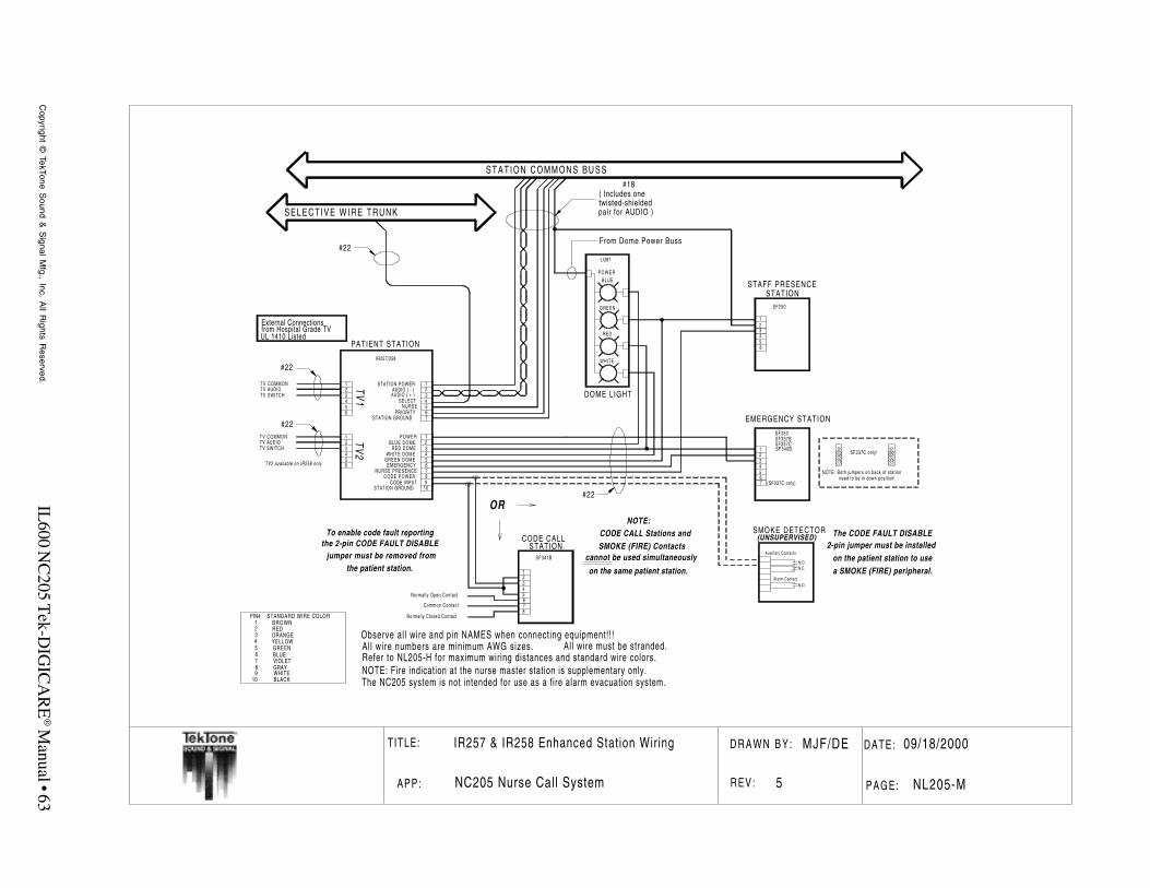
IL600 N
C205 T
ek-DIG
ICA
RE
® Manual • 63
Copyright ©
TekTone Sound &
Signal M
fg., Inc. All R
ights Reserved.
T ITLE: DATE:D R A W N B Y :
REV: PAGE:APP:
09/18/2000
NL205-M
MJF/DE
5NC205 Nurse Call System
Auxillary Contacts
Alarm ContactN.O.
N.O.N.C.
DOME LIGHT
SMOKE DETECTOR
STATION COMMONS BUSS
SELECTIVE WIRE TRUNK
#22
#18
pair for AUDIO )
( Includes onetwisted-shielded
STAFF PRESENCESTATION
CODE CALLSTATION
ORNOTE:
CODE CALL Stations andSMOKE (FIRE) Contacts
cannot be used simultaneously
on the same patient station.
The CODE FAULT DISABLE2-pin jumper must be installed
on the patient station to usea SMOKE (FIRE) peripheral.
#22
the 2-pin CODE FAULT DISABLEjumper must be removed from
the patient station.
To enable code fault reporting
EMERGENCY STATION
PATIENT STATION
STATION POWERAUDIO ( - )
AUDIO ( + )SELECT
NURSEPRIORITY
STATION GROUND
1234567
1234567
STATION GROUND
89
10
POWER
WHITE DOME
EMERGENCY
123456
SF330SF337B
SF340B
POWER
GREEN
LI387
BLUE
RED
WHITEIR257/258
BLUE DOMERED DOME
GREEN DOME
NURSE PRESENCECODE POWER
CODE INPUT
12345678
SF341B
123456
SF250
123456
123456
TV COMMONTV AUDIOTV SWITCH
TV COMMONTV AUDIOTV SWITCH
TV1
TV2
TV2 available on IR258 only
#22
#22
(UNSUPERVISED)
NOTE: Both jumpers on back of stationneed to be in down position!
����
��SF337C only!
SF337C
Normally Open Contact
Common Contact
Normally Closed Contact
External Connectionsfrom Hospital Grade TVUL 1410 Listed
From Dome Power Buss
7 (SF337C only)
IR257 & IR258 Enhanced Station Wiring
Refer to NL205-H for maximum wiring distances and standard wire colors.All wire numbers are minimum AWG sizes.Observe all wire and pin NAMES when connecting equipment!!!
All wire must be stranded.
NOTE: Fire indication at the nurse master station is supplementary only.The NC205 system is not intended for use as a fire alarm evacuation system.
BROWNREDORANGEYELLOWGREENBLUEVIOLETGRAYWHITEBLACK
123456789
10
PIN# STANDARD WIRE COLOR
Auxi l lary Contacts
Alarm ContactN.O.
N.O.N.C.
DOME LIGHT
SMOKE DETECTOR
S T A T I O N C O M M O N S B U S S
SELECTIVE WIRE TRUNK
#22
#18
pair for AUDIO )
( Includes onetwisted-shielded
STAFF PRESENCESTATION
CODE CALLSTATION
ORNOTE:
CODE CALL Stations andSMOKE (FIRE) Contacts
cannot be used simultaneously
on the same patient station.
The CODE FAULT DISABLE2-pin jumper must be installed
on the patient station to usea SMOKE (FIRE) peripheral.
#22
the 2-pin CODE FAULT DISABLEjumper must be removed from
the patient station.
To enable code fault reporting
EMERGENCY STATION
PATIENT STATION
STATION POWERAUDIO ( - )AUDIO ( + )
SELECTNURSE
PRIORITYSTATION GROUND
1234567
1234567
STATION GROUND
89
10
P O W E R
WHITE DOME
EMERGENCY
123456
SF330SF337B
SF340B
P O W E R
GREEN
LI387
BLUE
RED
WHITEIR257/258
BLUE DOMERED DOME
GREEN DOME
NURSE PRESENCECODE POWER
CODE INPUT
12345678
SF341B
123456
SF250
123456
123456
TV COMMONTV AUDIOTV SWITCH
TV COMMONTV AUDIOTV SWITCH
TV1
TV2
TV2 available on IR258 only
#22
#22
(UNSUPERVISED)
NOTE: Both jumpers on back of stat ionneed to be in down position!
��
��SF337C only!
SF337C
Normally Open Contact
Common Contact
Normally Closed Contact
External Connectionsfrom Hospital Grade TVUL 1410 Listed
From Dome Power Buss
7 (SF337C only)
Refer to NL205-H for maximum wiring distances and standard wire colors.All wire numbers are minimum AWG sizes.Observe all wire and pin NAMES when connecting equipment!!!
All wire must be stranded.
NOTE: Fire indication at the nurse master station is supplementary only.The NC205 system is not intended for use as a fire alarm evacuation system.
BROWNREDORANGEYELLOWGREENBLUEVIOLETGRAYWHITEBLACK
123456789
10
PIN# STANDARD WIRE COLOR

64 • IL600 N
C205 Tek-D
IGIC
AR
E® M
anualC
opyright © TekTone S
ound & S
ignal Mfg., Inc. A
ll Rights R
eserved.
T ITLE: DATE:D R A W N B Y :
REV: P A G E :APP:
12 /07 /98
NL205 -N
M J F / D E
5NC205 Nurse Cal l System
IR260A & LI388A Wiring
STATION COMMONS BUSS
SELECTIVE WIRE TRUNK
#22
#18
ZONE BUSS
#18
ZONE LIGHT
LI388A
DOME LIGHT
pair for AUDIO )
( Includes onetwisted-shielded
EMERGENCY STATION
DUTY STATION
STATION POWERAUDIO ( - )
AUDIO ( + )SELECT
NURSEPRIORITY
STATION GROUND
1234567
123456789
10
123456
SF330
SF340B
POWER
GREEN
LI387
BLUE
RED
WHITEIR260A
123456 STATION GROUND
ZONE DATA 0ZONE DATA 1ZONE DATA 2ZONE SELECT
123456
ZONE DATA 0ZONE DATA 1ZONE DATA 2ZONE SELECT
ZONE POWER
SYSTEM GROUND
7 (SF337C only)
SF337C
NOTE: Both jumpers on back of stationneed to be in down position!
��
��SF337C only!
From Dome Power Buss
7
DOME POWER
From Dome Power Buss
POWERSTATION GROUND
EMERGENCYSLOW FLASH IN
SLOW FLASH OUTWHITE DOME
BLUE DOMERED DOME
GREEN DOMEN/A
Refer to NL205-H for maximum wiring distances and standard wire colors.All wire numbers are minimum AWG sizes.Observe all wire and pin NAMES when connecting equipment!!!
All wire should be stranded. FLASHER BUSS
NOTE:NC205 system is limited to 8 duty devices ifPK261A Dome Lamp Power Supply is not used.These duty devices may be LI388A or IR260Awith dome lamps, in any combination, butcannot exceed 8 maximum. Reference NL205-Efor alternate dome power connection.
BROWNREDORANGEYELLOWGREENBLUEVIOLETGRAYWHITEBLACK
123456789
10
PIN# STANDARD WIRE COLOR

IL600 N
C205 T
ek-DIG
ICA
RE
® Manual • 65
Copyright ©
TekTone Sound &
Signal M
fg., Inc. All R
ights Reserved.
T ITLE: DATE:D R A W N B Y :
REV: PAGE:APP:
09/18/2000
NL205-O
MJF/DE
5NC205 Nurse Cal l System
A u x i l l a r y C o n t a c t s
A l a r m C o n t a c tN . O .
N . O .N . C .
SMOKE DETECTOR
STATION COMMONS BUSS
SELECTIVE WIRE TRUNK
#22
#18
pair for AUDIO )
( Includes onetwisted-shielded
MULTI-PURPOSE STATION
OR
NOTE:CODE CALL Stations andSMOKE (FIRE) Contacts
cannot be used simultaneouslyon the same patient station.
The CODE FAULT DISABLE2-pin jumper must be installed
on the patient station to usea SMOKE (FIRE) peripheral.
#22
the 2-pin CODE FAULT DISABLEjumper must be removed from
the patient station.
To enable code fault reporting
+
RECOMMENDATIONS :
: 60 ohm nominal impedanceCALL LEDIN-USE LED
CALL BUTTON
SPEAKER
RESET BUTTON
: Standard Yellow ( Vf ~ 2.0 ): Standard Red ( Vf ~ 2.0 )
: SPST momentary contact: SPST momentary contact
SPEAKER
RESET BUTTON
CALL LED
CALL BUTTON
IN-USE LED
-
#18twisted-shielded
#22
DOME LIGHT
STAFF PRESENCESTATION
EMERGENCY STATION
STATION POWERAUDIO ( - )
AUDIO ( + )SELECT
NURSEPRIORITY
STATION GROUND
1234567
1234567
STATION GROUND
89
10
POWER
WHITE DOME
EMERGENCY
123456
SF330SF337B
SF340B
POWER
GREEN
LI387
BLUE
RED
WHITE
IR259
BLUE DOMERED DOME
GREEN DOME
NURSE PRESENCE
123456
SF250
CODE CALLSTATION
12345678
SF341B
CODE POWERCODE INPUT
CALL LED12345678
CALL BUTTONRESET BUTTONIN-USE LEDAUDIO ( - )AUDIO ( + )
STATION POWER
(UNSUPERVISED)
Normally Open Contact
Common Contact
Normally Closed Contact
NOTE: Both jumpers on back of stationneed to be in down position!
��
��SF337C only!
SF337C
7 (SF337C only)
From Dome Power Buss
IR259 Enhanced Station Wiring
All wire numbers are minimum AWG sizes.Observe all wire and pin NAMES when connecting equipment!!!
All wire must be stranded.
NOTE: Fire indication at the nurse master station is supplementary only.The NC205 system is not intended for use as a fire alarm evacuation system.
Refer to NL205-H for maximum wiring distances and standard wire colors.
BROWNREDORANGEYELLOWGREENBLUEVIOLETG R A YWHITEB L A C K
123456789
10
PIN# STANDARD WIRE COLOR
Auxillary Contacts
Alarm ContactN.O.
N.O.N.C.
S M O K E D E T E C T O R
STATION COMMONS BUSS
SELECTIVE WIRE TRUNK
#22
#18
pair for AUDIO )
( Includes onetwisted-shielded
MULTI -PURPOSE STATION
OR
NOTE:CODE CALL Stations andSMOKE (FIRE) Contacts
cannot be used simultaneouslyon the same patient station.
The CODE FAULT DISABLE2-pin jumper must be installed
on the patient station to usea SMOKE (FIRE) peripheral.
#22
the 2-pin CODE FAULT DISABLEjumper must be removed from
the patient station.
To enable code fault reporting
+
RECOMMENDATIONS :
: 60 ohm nominal impedanceCALL LEDIN-USE LED
CALL BUTTON
SPEAKER
RESET BUTTON
: Standard Yellow ( Vf ~ 2.0 ): Standard Red ( Vf ~ 2.0 )
: SPST momentary contact: SPST momentary contact
SPEAKER
RESET BUTTON
CALL LED
CALL BUTTON
IN-USE LED
-
#18twisted-shielded
#22
DOME LIGHT
STAFF PRESENCESTATION
EMERGENCY STATION
STATION POWERAUDIO ( - )
AUDIO ( + )SELECT
NURSEPRIORITY
STATION GROUND
1234567
1234567
STATION GROUND
89
10
POWER
WHITE DOME
EMERGENCY
123456
SF330SF337B
SF340B
POWER
GREEN
LI387
BLUE
RED
WHITE
IR259
BLUE DOMERED DOME
GREEN DOME
NURSE PRESENCE
123456
SF250
CODE CALLSTATION
12345678
SF341B
CODE POWERCODE INPUT
CALL LED12345678
CALL BUTTONRESET BUTTONIN-USE LEDAUDIO ( - )AUDIO ( + )
STATION POWER
(UNSUPERVISED)
Normally Open Contact
Common Contact
Normally Closed Contact
NOTE: Both jumpers on back of stationneed to be in down position!
��
��
SF337C only!
SF337C
7 (SF337C only)
From Dome Power Buss
All wire numbers are minimum AWG sizes.Observe all wire and pin NAMES when connecting equipment!!!
All wire must be stranded.
NOTE: Fire indication at the nurse master station is supplementary only.The NC205 system is not intended for use as a fire alarm evacuation system.
Refer to NL205-H for maximum wiring distances and standard wire colors.
B R O W NR E DO R A N G EY E L L O WG R E E NB L U EV I O L E TG R A YW H I T EB L A C K
123456789
1 0
P I N # S T A N D A R D W I R E C O L O R
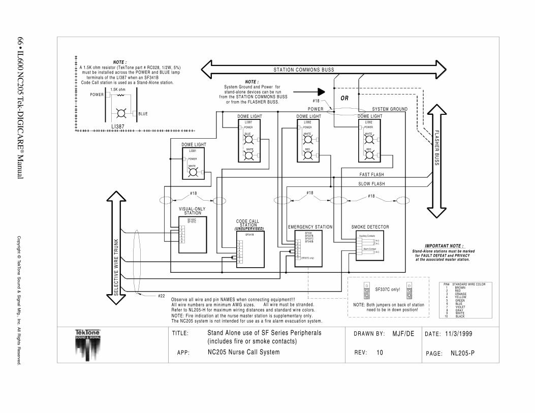
66 • IL600 N
C205 Tek-D
IGIC
AR
E® M
anualC
opyright © TekTone S
ound & S
ignal Mfg., Inc. A
ll Rights R
eserved.
T ITLE: DATE:D R A W N B Y :
REV: PAGE:APP:
11/3/1999
NL205-P
MJF/DE
10
Stand Alone use of SF Series Peripherals
NC205 Nurse Cal l System
(includes fire or smoke contacts)
Auxillary Contacts
Alarm ContactN.O.
N.O.N.C.
STAT ION COMMONS BUSS
SE
LEC
TIV
EW
IRE
TRU
NK
FLAS
HE
RB
US
S
#18
CODE CALLSTATION
DOME LIGHTLI387
FAST FLASH
SLOW FLASH
#18
#22
P O W E R SYSTEM GROUND
NOTE :System Ground and Power forstand-alone devices can be run
from the STATION COMMONS BUSSor from the FLASHER BUSS.
WHITE
POWER
DOME LIGHTLI381
WHITE
POWER
12345678
SF341B
EMERGENCY STATION SMOKE DETECTOR
OR
BLUE
POWER1.5K ohm
NOTE :
LI387
A 1.5K ohm resistor (TekTone part # RC028, 1/2W, 5%)must be insta l led across the POWER and BLUE lamp
terminals of the LI387 when an SF341BCode Call stat ion is used as a Stand-Alone stat ion.
#18
BLUE
123456
SF100C
VISUAL-ONLYSTATION
#18
Stand-Alone stations must be markedfor FAULT DEFEAT and PRIVACYat the associated master station.
IMPORTANT NOTE :
DOME LIGHTLI382
RED
POWER
WHITE
DOME LIGHTLI382
RED
POWER
WHITE
(UNSUPERVISED)
123456
SF337B
7 (SF337C only)
SF330
SF337CSF340B
NOTE: Both jumpers on back of stat ionneed to be in down posit ion!
���
���
���
���
SF337C only!
Refer to NL205-H for maximum wir ing distances and standard wire colors.A l l w i re numbers are min imum AWG sizes.Observe al l w i re and pin NAMES when connect ing equipment ! ! !
A l l wi re must be stranded.
NOTE: Fi re indicat ion at the nurse master stat ion is supplementary only .The NC205 system is not in tended for use as a f i re a larm evacuat ion system.
SF101C
BROWNREDORANGEYELLOWGREENBLUEVIOLETGRAYWHITEBLACK
123456789
10
PIN# STANDARD WIRE COLOR
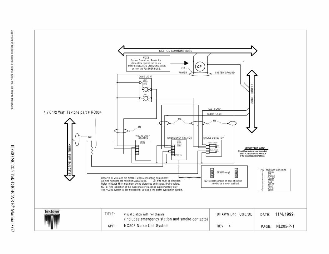
IL600 N
C205 T
ek-DIG
ICA
RE
® Manual • 67
Copyright ©
TekTone Sound &
Signal M
fg., Inc. All R
ights Reserved.
T ITLE: DATE:D R A W N B Y :
REV: PAGE:APP: NL205-P-1NC205 Nurse Cal l System
(includes emergency stat ion and smoke contacts)
Auxillary Contacts
Alarm ContactN . O .
N . O .N . C .
STATION COMMONS BUSS
SE
LEC
TIV
EW
IRE
TRU
NK
FLAS
HE
RB
US
S
#18
DOME LIGHTLI387
FAST FLASH
SLOW FLASH
#18
#22
POWER SYSTEM GROUND
NOTE :System Ground and Power forstand-alone devices can be run
from the STATION COMMONS BUSSor from the FLASHER BUSS.
WHITEPOWER
EMERGENCY STATION SMOKE DETECTOR
OR#18
123456
SF100C
VISUAL-ONLYSTATION
#18
Stand-Alone stations must be markedfor FAULT DEFEAT and PRIVACYat the associated master station.
IMPORTANT NOTE :123456
SF337B
7 (SF337C only)
SF330
SF337CSF340B
NOTE: Both jumpers on back of stationneed to be in down position!
���
���
���
SF337C only!
Refer to NL205-H for maximum wiring distances and standard wire colors.All wire numbers are minimum AWG sizes.Observe all wire and pin NAMES when connecting equipment!!!
All wire must be stranded.
NOTE: Fire indication at the nurse master station is supplementary only.The NC205 system is not intended for use as a fire alarm evacuation system.
SF101C
RED
11/4/1999Visual Stat ion With Peripherals
4.7K 1/2 Watt Tektone part # RC034
C G B / D E
4
BROWNREDORANGEYELLOWGREENBLUEVIOLETGRAYWHITEBLACK
123456789
10
PIN# STANDARD WIRE COLOR

68 • IL600 N
C205 Tek-D
IGIC
AR
E® M
anualC
opyright © TekTone S
ound & S
ignal Mfg., Inc. A
ll Rights R
eserved.
T ITLE: D R A W N B Y :
REV:APP:
MJF
9NC205 Nurse Call System
110 VACTerminal Block
Ground Lug
Line
Neutral
Ground
BlueBrownGreen
NOTE: This power inputmust be connected sothat the NC260B & thePK261A receive power atthe same time.
NC260B Cabinet
Connect to good Earth Ground
NC260B/2A 120 VAC Connect ion Diagram
110 VACTerminal Block
Ground Lug
110 VACTerminal Block
Ground Lug
Single Point GroundMethodology
NC260BCabinet
NC262ACabinet
#14 Gauge
Good Earth Ground Good Earth Ground
DATE:
P A G E :
11/3/1999
NL205-Q
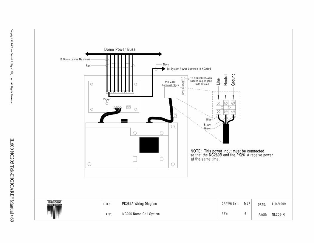
IL600 N
C205 T
ek-DIG
ICA
RE
® Manual • 69
Copyright ©
TekTone Sound &
Signal M
fg., Inc. All R
ights Reserved.
T ITLE:
APP:
PK261A Wir ing Diagram
NC205 Nurse Cal l System
PowerL E D
Dome Power Buss
To Sys tem Power Common in NC260B
110 VACTerminal Block
Ground
Lug
Line
Neu
tral
Gro
und
B lue
BrownGreen
16 Dome Lamps Max imum
Red Black
NOTE: This power input must be connectedso that the NC260B and the PK261A receive powerat the same time.
To NC260B ChassisGround Lug or good
Earth Ground
DRAWN BY:
REV:
M J F
6
DATE:
PAGE:
11/4/1999
NL205-R

70 • IL600 N
C205 Tek-D
IGIC
AR
E® M
anualC
opyright © TekTone S
ound & S
ignal Mfg., Inc. A
ll Rights R
eserved.
T ITLE: DATE:D R A W N B Y :
REV: PAGE:APP:
11/3/1999
NL205-S
MJF
3
Battery Kit Installation
NC205 Nurse Cal l System
NC260B Central Equipment
NO
TE:A
llw
irenu
mbe
rsar
em
inim
umAW
Gsi
zes.
PK260 Power Supply
or NC262A Central Expander
4 pin Header 2 pin Header
SYSTEMPOWER
BACKUPBATTERY
+- BATTERY +-
R E DB L A C K
Instal lat ion of the BA002K:1. Place batter ies (Tektone part number BA001) into
bottom of IH260 chassis as indicated in diagram.2. Mount included support brackets (Tektone part
number CL135) to IH260 using inc luded hardware.3. Connect battery wir ing harness as indicated in
diagram.4. Plug battery wir ing harness interconnect plug into
receptacle provided on motherboard (Tektone partnumber PM260B) wi th system power on.
Replacement of the BA002K:1. Remove battery interconnect plug from motherboard
receptacle.2. Remove battery wir ing harness.3. Remove battery support brackets.4. Remove old batter ies from system housing and
replace with new batter ies (12 VDC 1.9AH - 2.0AH).5. Reinstal l battery support brackets.6. Connect battery wir ing harness as indicated in
diagram.7. Plug battery wir ing harness interconnect plug into
receptacle provided on motherboard with
BA001BATTERYBA001
CL135 supportbracket
CL135 supportbracket
PM260B Motherboard
2 - #16 gauge wiresupplied as part of
battery kit
1 - #16 gauge wiresupplied as part of
battery kit
BATTERY WIRING HARNESS
BATTERY WIRING HARNESS
Interconnect Plug
HW002 nutHW069 lockwasherHW214 f la t washer
HW022 bol t
system power on.