Embed Size (px)
Citation preview
PROJECT: IIT MADRAS RESEARCH PARK-CHENNAI ,
TECHNICAL SPECIFICATION FOR CCTV AND ACCESS CONTROL SYSTEM TENDER
INDEX
S NO DESCRIPTION
1 Introduction
2 Standards & Regulations
3 IP Based Closed Circuit Television
4 Access Control System
5 Technical Sheet Submittal
6 List of Tender Drawing
1.0 INTRODUCTION 1.1 Project Overview
Indian Institute of technical (IIT) Research Park at Chennai proposed building consisting of 5 blocks in Phase -2, i.e.
• Block –A GF +10 Floors
• Block –B GF +10 Floors
• Block –C GF +08 Floors
• Block –D Basement, GF +10 Floors
• Block –E GF +5 Floors for multilevel car parking
Refer the tender drawings for floor area details and understanding of project. The contractor
suggested offering the tender after the site visit of proposed building.
1.2 Scope
The scope of work shall include Design, Supply, Installation, Testing and Commissioning& Handing
over of the Integrated Building Management Systems.
The Fire safety and security systems of following have been covered in this tender as follows;
1. Automatic Fire detection and alarm system - FAS
2. Public address system for general cum emergency announcement – PAS
3. IP based Closed circuit television system – IP CCTV
4. Automatic gate management system with Boom Barriers & Tripod
5. Back bone system for Data & voice
The Integrated Building Management Systems - IBMS shall incorporate the following equipment for
integrate, monitor, maintain and control the equipment:
1. Chiller plant integration
2. Air Handling Units
3. VFD & VAV Units
4. Ventilation and Exhaust System
The system should be able to provide the following integration and provide consumption report of fit out areas.
1. Energy Meter integration

2. BTU calculation via BMS logic
The system should have open integration in terms of monitoring the chiller parameters and generate
necessary report via Modbus protocol.
Also the system should be able to provide the following integration and provide parameters in the
IBMS system.
1. PA Integration 2. LIFT integration 3. DG Integration 4. FAS Integration 5. Water management System 6. CCTV Integration for proposed & existing building 7. Access integration
The Details scope of system shall be described under the relevant subsystems. The work under this system shall consist of supply, installation, testing, training & handing over of
all materials, equipment, hardware, software appliances and necessary labour to commission they
said system, complete with all the required components strictly as per the enclosed design
specifications, design details. The scope also include the supply, installation & commissioning of any
material or equipment including civil works that are not specifically mentioned in the specifications
and design details but are required for successful commissioning of the project.
1.3 Coordination of work with IIT
• Coordinate the work of this division with the work of all other supply items by IIT team and the
incubator company and so arrange that there will be no delay in the proper installation and
completion of any part or parts of each respective work wherein it may be interrelated with that
of this Contract so that generally all construction work can proceed without delaying the
completion of the project.
• Examine contract drawings and specifications for all other trades relating to this project, verify all
governing conditions at the site, and become fully informed as to the extent and character of the
work required and its relation to other work in the building. No consideration will be granted for
any alleged misunderstanding of the materials to be furnished for work to be done.
• Scaled and figured dimensions with respect to the items are approximate only; sizes of
equipment have been taken from typical equipment items of the class indicated. Before
proceeding with work, carefully check all dimensions and sizes and assume full responsibility for
the fitting-in of equipment and materials to the building and to meet architectural and structural
conditions.
• Coordinate work with other disciplines. Confer with other contractors whose work might affect
this installation and arrange all parts of this work and equipment in proper relation to the work
and equipment of others, with the building construction and with architectural finish so that this
work will harmonize in service, appearance, and function.
• Install exposed piping to provide the maximum amount of headroom coordinated with the
Architectural drawings above the finished floor. Install piping concealed in areas where hung
ceilings or other furred spaces are indicated.
• Refer to the Architectural Drawings for ceiling heights, locations and types of hung ceilings and
furred spaces.
• Furnish to the OEM guidelines for general construction, detailed advance information regarding
all requirements related to work under other Divisions and/or Sections. Furnish sizes, accurate
data, and locations of any and all pads, pits, chases, sleeves, and slots through floor slabs, walls,
foundations, ceilings, roof, and other special openings required for work under this Division.
****************
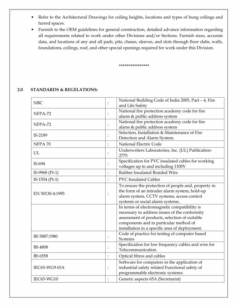
2.0 STANDARDS & REGELATIONS:
NBC : National Building Code of India 2005, Part – 4, Fire and Life Safety
NFPA-72 : National fire protection academy code for fire alarm & public address system
NFPA-72 : National fire protection academy code for fire alarm & public address system
IS-2189 : Selection, Installation & Maintenance of Fire Detection and Alarm System.
NFPA 70 : National Electric Code
UL : Underwriters Laboratories, Inc. (UL) Publication- 2775
IS-694 : Specification for PVC insulated cables for working voltages up to and including 1100V
IS-9968 (Pt-1) : Rubber Insulated Braided Wire
IS-1554 (Pt-1) : PVC Insulated Cables
EN 50130-4:1995 :
To ensure the protection of people and, property in the form of an intruder alarm system, hold-up alarm system, CCTV systems, access control systems or social alarm systems.
In terms of electromagnetic compatibility is necessary to address issues of the conformity assessment of products, selection of suitable components and in particular method of installation in a specific area of deployment.
BS 5887:1980 : Code of practice for testing of computer based Systems
BS 4808 : Specification for low frequency cables and wire for Telecommunication
BS 6558 : Optical fibres and cables
IEC65-WG9 65A : Software for computers in the application of industrial safety related Functional safety of programmable electronic systems:
IEC65-WG10 : Generic aspects 65A (Secretariat)
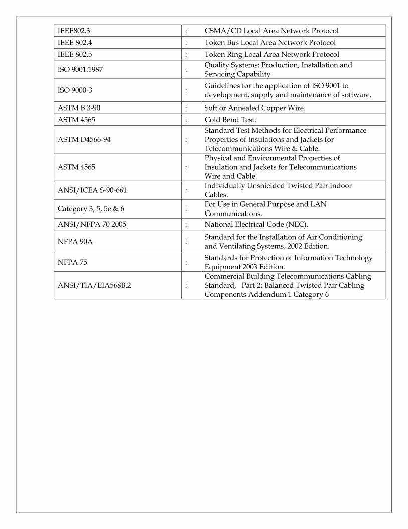
IEEE802.3 : CSMA/CD Local Area Network Protocol
IEEE 802.4 : Token Bus Local Area Network Protocol
IEEE 802.5 : Token Ring Local Area Network Protocol
ISO 9001:1987 : Quality Systems: Production, Installation and Servicing Capability
ISO 9000-3 : Guidelines for the application of ISO 9001 to development, supply and maintenance of software.
ASTM B 3-90 : Soft or Annealed Copper Wire.
ASTM 4565 : Cold Bend Test.
ASTM D4566-94 : Standard Test Methods for Electrical Performance Properties of Insulations and Jackets for Telecommunications Wire & Cable.
ASTM 4565 : Physical and Environmental Properties of Insulation and Jackets for Telecommunications Wire and Cable.
ANSI/ICEA S-90-661 : Individually Unshielded Twisted Pair Indoor Cables.
Category 3, 5, 5e & 6 : For Use in General Purpose and LAN Communications.
ANSI/NFPA 70 2005 : National Electrical Code (NEC).
NFPA 90A : Standard for the Installation of Air Conditioning and Ventilating Systems, 2002 Edition.
NFPA 75 : Standards for Protection of Information Technology Equipment 2003 Edition.
ANSI/TIA/EIA568B.2 : Commercial Building Telecommunications Cabling Standard, Part 2: Balanced Twisted Pair Cabling Components Addendum 1 Category 6
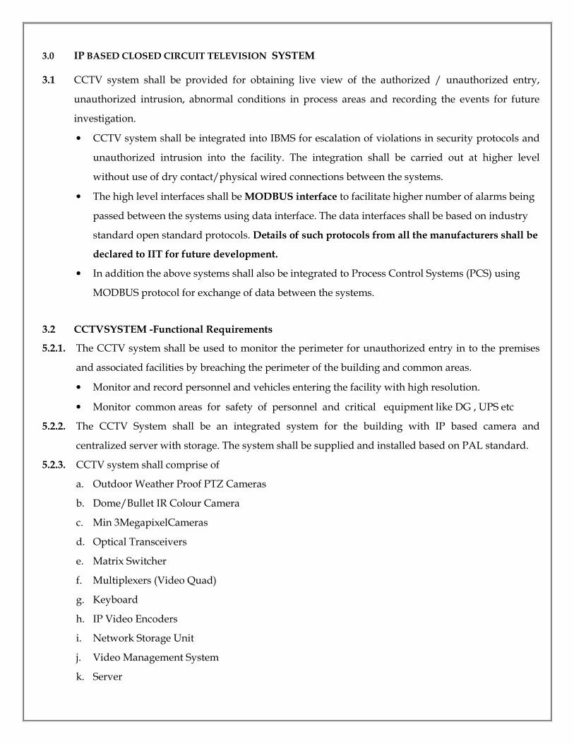
3.0 IP BASED CLOSED CIRCUIT TELEVISION SYSTEM
3.1 CCTV system shall be provided for obtaining live view of the authorized / unauthorized entry,
unauthorized intrusion, abnormal conditions in process areas and recording the events for future
investigation.
• CCTV system shall be integrated into IBMS for escalation of violations in security protocols and
unauthorized intrusion into the facility. The integration shall be carried out at higher level
without use of dry contact/physical wired connections between the systems.
• The high level interfaces shall be MODBUS interface to facilitate higher number of alarms being
passed between the systems using data interface. The data interfaces shall be based on industry
standard open standard protocols. Details of such protocols from all the manufacturers shall be
declared to IIT for future development.
• In addition the above systems shall also be integrated to Process Control Systems (PCS) using
MODBUS protocol for exchange of data between the systems.
3.2 CCTVSYSTEM -Functional Requirements
5.2.1. The CCTV system shall be used to monitor the perimeter for unauthorized entry in to the premises
and associated facilities by breaching the perimeter of the building and common areas.
• Monitor and record personnel and vehicles entering the facility with high resolution.
• Monitor common areas for safety of personnel and critical equipment like DG , UPS etc
5.2.2. The CCTV System shall be an integrated system for the building with IP based camera and
centralized server with storage. The system shall be supplied and installed based on PAL standard.
5.2.3. CCTV system shall comprise of
a. Outdoor Weather Proof PTZ Cameras
b. Dome/Bullet IR Colour Camera
c. Min 3MegapixelCameras
d. Optical Transceivers
e. Matrix Switcher
f. Multiplexers (Video Quad)
g. Keyboard
h. IP Video Encoders
i. Network Storage Unit
j. Video Management System
k. Server
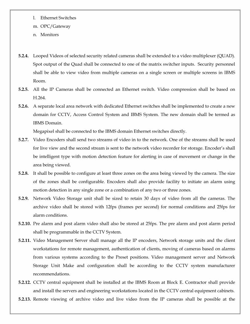
l. Ethernet Switches
m. OPC/Gateway
n. Monitors
5.2.4. Looped Videos of selected security related cameras shall be extended to a video multiplexer (QUAD).
Spot output of the Quad shall be connected to one of the matrix switcher inputs. Security personnel
shall be able to view video from multiple cameras on a single screen or multiple screens in IBMS
Room.
5.2.5. All the IP Cameras shall be connected an Ethernet switch. Video compression shall be based on
H.264.
5.2.6. A separate local area network with dedicated Ethernet switches shall be implemented to create a new
domain for CCTV, Access Control System and IBMS System. The new domain shall be termed as
IBMS Domain.
Megapixel shall be connected to the IBMS domain Ethernet switches directly.
5.2.7. Video Encoders shall send two streams of video in to the network. One of the streams shall be used
for live view and the second stream is sent to the network video recorder for storage. Encoder’s shall
be intelligent type with motion detection feature for alerting in case of movement or change in the
area being viewed.
5.2.8. It shall be possible to configure at least three zones on the area being viewed by the camera. The size
of the zones shall be configurable. Encoders shall also provide facility to initiate an alarm using
motion detection in any single zone or a combination of any two or three zones.
5.2.9. Network Video Storage unit shall be sized to retain 30 days of video from all the cameras. The
archive video shall be stored with 12fps (frames per second) for normal conditions and 25fps for
alarm conditions.
5.2.10. Pre alarm and post alarm video shall also be stored at 25fps. The pre alarm and post alarm period
shall be programmable in the CCTV System.
5.2.11. Video Management Server shall manage all the IP encoders, Network storage units and the client
workstations for remote management, authentication of clients, moving of cameras based on alarms
from various systems according to the Preset positions. Video management server and Network
Storage Unit Make and configuration shall be according to the CCTV system manufacturer
recommendations.
5.2.12. CCTV central equipment shall be installed at the IBMS Room at Block E. Contractor shall provide
and install the servers and engineering workstations located in the CCTV central equipment cabinets.
5.2.13. Remote viewing of archive video and live video from the IP cameras shall be possible at the
following locations.
• IBMS Room
• Authorized personal at client side like FMS team
5.2.14. Building indoors shall be provided with Indoor IP bullet min 3 Megapixel cameras to monitor the
common area’s movement like lift lobby.
5.2.15. Min 3 Megapixel cameras shall be installed at the entry gates to monitor personnel and vehicles
entering the facility. This is in order to clearly identify personnel and vehicle numbers, vehicle types
in case of incident investigation. Two cameras shall be positioned at difference heights to view inside
of Trucks and Cars driver’s cabin.
5.2.16. All Outdoor cameras Maximum coverage shall be achieved by positioning of cameras in optimised
locations. Position of cameras shall be closely coordinated with the operations team and security
team during the execution stage of the project.
5.2.17. Megapixel cameras shall be connected via CAT6 cables to the IBMS Domain Ethernet Switch.
5.2.18. To ensure stability in the picture all outdoor cameras shall be installed on wall using with mounting
bracket to a maximum possible extent or else mounting GI poles.
5.2.19. Perimeter Security cameras shall be mounted on the boundary wall. Boundary wall shall have
reinforced concrete columns for installation of cameras.
5.2.20. The IP Based Video Management System shall provide an open standard interface for high level
integration with Access Control and IBMS system for moving cameras to preset positions in case of
an alarm or an event.
5.2.21. IBMS Room shall be provided with 36” High definition LED monitors mounted on wall for viewing
of video and Client Workstation.
3.3 TECHNICALREQUIREMENTS
3.3.1 PTZ OUTDOOR CAMERAS
i. Camera shall be high resolution 1/3” CCD colour cameras. PTZ cameras shall be provided with
facilities that include pan, tilt and motorized zoom lens.
ii. Contractor shall submit the calculation the lens and focal length requirements to meet the
coverage required during the execution. However the motorized
zoomlensshallofferaminimum20:1zoomratio, continuously variable between 10mm (wide angle)
and 200mm (telephoto) as minimum. The camera shall have auto focus and auto iris features.
iii. Pan rotation shall be 360 Deg continuous endless panning and tilt rotation shall be at least +/-90
Deg from Horizontal position. The camera shall support Variable high speed Pan and Tilt
functions such that the target can be spotted and focused instantaneously when a preset function
is triggered or when the operator is moving the camera.
iv. Programmable pre-set positions for pan, tilt and zoom shall be available that allows the operation
of a surveillance ‘tour’ of each similarly equipped camera. The camera shall support a minimum
of 125 preset positions and 6 tours. The preset positions shall include Pan, Tilt, Zoom with
Autofocus and Auto Iris. Clear picture shall be visible on the screen immediately after triggering
a preset position.
v. The cameras shall be installed in an environmental housing to meet the area certification and
equipped with wind screen, demister, sun shield and wipe.
vi. Cameras shall be of Day/Night Wide Dynamic Range type and shall operate satisfactorily at light
levels above 0.05lux. In the event of light levels being lower than that able to support colour
reproduction, the camera shall be capable of automatically switching from colour to monochrome
operation that enables the camera to operate at light levels of 0.001lux. The cameras shall be fitted
with an auto-iris function to compensate for vary in light level conditions.
vii. Cameras shall be installed at suitable position in alignment with the lights such that a clear view
is obtained on the monitor.
3.3.2 MEGAPIXELBULLETCAMERAS
i. Megapixel fixed cameras shall be used at the security gates, Common areas and IBMS room for
monitoring and high resolution recording of personnel and vehicles entering the facility. The
cameras shall be positioned properly to identify personnel and vehicle number plates by zooming
into the picture for investigation in future.
ii. The cameras shall provide a minimum of 3 Megapixel resolutions with 25fps. The camera shall
support various resolution settings in the configuration.
iii. The cameras shall be powered from the IBMS domain Ethernet Switch using Power over Ethernet
(POE). External Power supply shall not be used. The camera shall support H.264 standard. It
shall provide a minimum of two video streams with one fixed high resolution for recording and
second with configurable resolution for live viewing of video.
iv. Manual Pan Rotation shall be +/- 180 Deg continuous and Manual tilt rotation shall be at least
+/- 90Deg with camera looking down.
v. Contractor shall submit their calculation the lens and focal length requirements to meet the
coverage required and determine the black spot.
vi. Cameras shall be of IR LED type @ 30 mts and shall operate satisfactorily at light levels above
0.5lux. In the event of light levels being lower than that able to support colour reproduction, the
camera shall be capable of automatically switching from colour to monochrome operation that
enables the camera to operate at light levels of 0.03lux. The cameras shall be fitted with an auto-
iris function to compensate for varying light level conditions.
vii. Cameras shall be installed at suitable position in alignment with the lights such that a clear view
is obtained on the monitor.
3.3.3 NETWORK STORAGE UNIT
i. Network storage unit shall be connected to the IBMS domain Ethernet switch
using10/100/1000Base Ethernet interface.
ii. The storage unit shall be sized to accommodate continuous video storage for 30 days as per the
requirements be low or 52TB (Tera Bytes) whichever is higher.
iii. 12fps for normal video 25 fps for alarm video with configurable prealarm and post alarm video
duration. The system shall record a minimum of 15 minutes pre alarm and 15minutes of post
alarm video storage at 25fps.
iv. Alarm duration shall be 1 hour per day per camera for storage sizing purposes. The storage unit
shall be provided with RAID 6 storage data protection against hard disk failure. The hard disks
shall be hot swappable.
v. The system shall have built in automatic defragmentation routines to avoid data getting
fragmented.
vi. The system shall record H.264 Compressed video from Cameras.
vii. The storage unit shall have redundant hot swappable power supply and fan units. The storage
unit shall support tagging of video.
viii. The network storage unit shall support a recording through put of 165Mbps to 330 Mbps of read
through put at all times. There shall be no limitation on the number of cameras being used with
the storage unit for recording or reading activity.
ix. The network storage unit shall be fully manageable using the Ethernet interface.
3.3.4 VIDEO MANAGEMENT SYSTEM SERVER
i. The Video Management System server shall be an integrated system that manages all the CCTV
system components IP cameras, Network Storage Unit. It shall
• Act as a Dynamic Host Configuration Protocol - DHCP server allocating IP address to all the
CCTV Equipment
• Hold configuration data base of the systems.
• Provide authentication, control and facilitate interaction between all the devices with in the
CCTV network.
• Act as an NTP server for service date and time to various system components. Shall be
capable of synchronising with external high accuracy time source.
• Shall manage security for all devices, clients, login, passwords, user groups, user privileges,
• Maintain a data base of device related alarms and associated videos for easy access in future.
• Maintain fault logs for various faults within the system.
• Manage storage unit of the CCTV system.
3.3.5 CLIENT AND ENGINEERING WORK STATIONS
i. The work station shall work as a HMI (Human Machine Interface) for the Video Management
System. The system shall
• Provide live and archive viewing of video from all the cameras.
• Provide full access to all the IP cameras including PTZ Control, Iris and Focus control,
Camera configuration, Preset configuration and Preset positioning etc.
• Have facility to load MAPs of the sites in various file formats including GIF, TIF, BMP, JPEG
and other Provided facility to have interleaved maps with embedded icons / hyperlinks to
camera and alarm device icons with expanded view of a part of the facility.
• Provide inter active configurable icons with facility to associate them with devices. The icons
shall support controlling of devices, know device status including alarms.
• Support dual monitors. In general one of the monitors shall be used for MAP and Icons view
and the second monitor for viewing of video from various sources.
• Facilitate writing of scripts and associating the scripts with alarms, icons and various devices.
• Act as virtual matrix and support mapping of video from any source to any monitor.
• Act as a virtual multiplexer (QUAD) and support viewing of up to 16 cameras in a single
screen simultaneously.
• Support time synchronised play of stored archive video of up to 16 cameras. Simultaneous
viewing of standard resolution and megapixel cameras must be possible on the same display.
• Support exporting of snap shots, video in various file formats including AVI, BMP and JPG.
The exported video shall be stored in transportable storage devices like CD/ DVDROM,
USB etc.
• Provide extensive alarm handling features including provision of help text for showing the
handling procedure for the specific alarm, write notes and feedback while activating or
acknowledging the alarms.
• Provide the ability to control and program any camera equipped with PTZ.
ii. The workstation shall be capable of the following operations
• Manually control the PTZ
• Set the pan /tilt home positions form annual or alarm activation
• Automatically control the cameras through an alarm trigger
• Ability to set multiple preset positions
• Ability to set multiple tours
• Remotely set and clear the movement limits of the pan / tilt mechanism from the control
room, through a telemetry unit at an outdoor camera site
• Adjust the zoom lens graphics file formats.
• Ability to control the camera menu and setup the camera through the IP video security
system
iii. The workstations shall be provided with two 21” High Definition LCD colour monitors with DVI
interface for view of standard resolution and megapixel cameras. Client work station shall only
have privileges to use the system. Engineering workstations shall be provided with privileges to
modify configuration of the entire CCTV system and associated components.
iv. It shall be possible to select any monitor to display live full screen single, sequential or multiple
pictures from any combination of cameras selected from the operator work station keyboard.
3.3.6 ETHERNETSWITCHES
i. Ethernet switches shall be minimum of 24 ports x 100 Base T and 4 x 1000 Base uplink interfaces.
ii. Suitable optical interface modules shall be provided for interconnecting switches at various
locations.
iii. Connectivity to network storage unit and Client workstation shall be1000 Base T.
iv. Cameras and video encoders shall be connected to theswitchesusing100BaseT ports.
3.3.7 GATEWAY
i. CCTV system shall be equipped with an Open Process Control or a Gateway device which can
exchange data between CCTV system Access Control System and Perimeter Intrusion Detection
system for meaningful integration of the three systems.
ii. The integration shall facilitate automated response of various security systems to unauthorised
intrusion alarms and escalation of alarms to Security personnel for further action.
iii. Integration shall beat a higher level using data interfaces, various protocols and exchange of data
between systems. Use of dry contacts for communicating alarms between systems is not acceptable.
3.3.8 NETWORK PoE SWITCH (10/100Mbps):
The network should have following features and specifications
FEATURES:
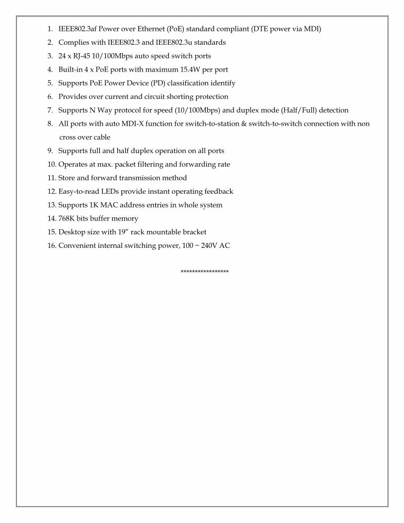
1. IEEE802.3af Power over Ethernet (PoE) standard compliant (DTE power via MDI)
2. Complies with IEEE802.3 and IEEE802.3u standards
3. 24 x RJ-45 10/100Mbps auto speed switch ports
4. Built-in 4 x PoE ports with maximum 15.4W per port
5. Supports PoE Power Device (PD) classification identify
6. Provides over current and circuit shorting protection
7. Supports N Way protocol for speed (10/100Mbps) and duplex mode (Half/Full) detection
8. All ports with auto MDI-X function for switch-to-station & switch-to-switch connection with non
cross over cable
9. Supports full and half duplex operation on all ports
10. Operates at max. packet filtering and forwarding rate
11. Store and forward transmission method
12. Easy-to-read LEDs provide instant operating feedback
13. Supports 1K MAC address entries in whole system
14. 768K bits buffer memory
15. Desktop size with 19” rack mountable bracket
16. Convenient internal switching power, 100 ~ 240V AC
*****************
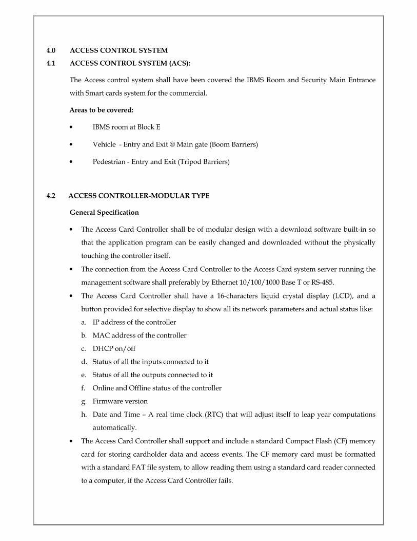
4.0 ACCESS CONTROL SYSTEM
4.1 ACCESS CONTROL SYSTEM (ACS):
The Access control system shall have been covered the IBMS Room and Security Main Entrance
with Smart cards system for the commercial.
Areas to be covered:
• IBMS room at Block E
• Vehicle - Entry and Exit @ Main gate (Boom Barriers)
• Pedestrian - Entry and Exit (Tripod Barriers)
4.2 ACCESS CONTROLLER-MODULAR TYPE
General Specification
• The Access Card Controller shall be of modular design with a download software built-in so
that the application program can be easily changed and downloaded without the physically
touching the controller itself.
• The connection from the Access Card Controller to the Access Card system server running the
management software shall preferably by Ethernet 10/100/1000 Base T or RS-485.
• The Access Card Controller shall have a 16-characters liquid crystal display (LCD), and a
button provided for selective display to show all its network parameters and actual status like:
a. IP address of the controller
b. MAC address of the controller
c. DHCP on/off
d. Status of all the inputs connected to it
e. Status of all the outputs connected to it
f. Online and Offline status of the controller
g. Firmware version
h. Date and Time – A real time clock (RTC) that will adjust itself to leap year computations
automatically.
• The Access Card Controller shall support and include a standard Compact Flash (CF) memory
card for storing cardholder data and access events. The CF memory card must be formatted
with a standard FAT file system, to allow reading them using a standard card reader connected
to a computer, if the Access Card Controller fails.

• The Access Card Controller memory shall under no circumstance lose a single, not even the
last transaction when power fails.
• The Access Card Controller and all devices connected to it shall continue to operate and
control access in off-line mode, even if the computer network fails.
• The Access Card Controller memory shall store database that has a capacity with a minimum
of 80,000 cardholders (upgradeable to 400,000), each having a programmable 10 digits
(personal Identification Number) PIN codes.
• The cardholder database shall be upgradeable by exchanging the CF card. The system shall
automatically detect the size of the CF-card.
• The Access Card Controller provided shall support the connectivity of up to 4 standard
Wiegand interface readers or up to serial interface readers operating on RS 485 bus technology.
• The Access Card Controller shall provide minimum eight programmable I/Os on board, and
shall be expandable to 56 each, using I/O extensions.
• All inputs provided shall be configurable to provide 2- or 4- status selectable, via End-Of-line
(EOL) resistors, namely:
a. Input Closed
b. Input Opened
c. Input Shorted (provided in 4- status mode)
d. Input Tamper (Cable cut, provided in 4- status mode)
• EOL resistor’s values shall be flexible selectable in the Access Control System management
software during configuration.
• UPS shall be provided to continually supply power to the Access Card Controller and readers
for a minimum of 2-hours, in the event of power failure subject to retrieve the power.
• The Access Card Controller shall generate a transaction record and save them in the memory
for every alarm, they include:
1. Time/date of occurrence and restoration.
2. Location of alarm sensors.
3. Surveillance of Employees/Regular Visitors/Casual Visitors: All personnel visiting the
buildings may be divided into three categories i.e. Employees, Regular Visitors (who are issued
passes for specific period of not more than 03 months) and Casual Visitors (who are issued
passes for the day). The system should be capable of the following :
a. Provision of unique Access Card having smart card technology.

b. Read facility.
c. Surveillance and recording of entry and exit of personnel through dedicated access doors.
d. Restricting access of visitors to specific office by creating electronic barriers.
e. Detection of a visitor who doesn’t meet designated officer or doesn’t report back at
reception/exit gate after meeting the officer in the given time frame.
f. Signage System within the building for Zone indication and evacuation.
g. A Central Video Display Unit and integrated public address system for parking areas and
building under the control of IBMS room or designated person on a single platform.
h. The Platform should provide for the flexibility of sending alert message/announcement to
particular individual/zone/entire buildings.
i. Power back up and inbuilt redundancy for each hardware. Provision for this feature may
be in-built in the system.
j. Integration of Pass Section – security cabin , Reception Offices and Main security officer
: System Architecture should cater for integration of Pass Section, Reception Offices and
the Central Control Unit for effective Pass and Vehicle management .
k. The ACCESS CONTROL SYSTEM shall be so designed that any failure of any sub-system
shall not affect the normal operation of another sub-system; they shall continue to operate
normally in a non-degraded mode.
l. The System Integrator/Firm submitting the Access control system Application Software
proposed for the project shall show proven operational record of such nature in their bid
documents.
m. The Access control software with GUI shall be capable to integrate with Facility
management software, visitors management system, Time and attendance software etc
(which is inclusive in this package).
n. The Software licensee will be multiuser package (N+2) with min capacity of 50000 card
holders.
4.3 SMART CARD READER:
General Specification
a. The Smart Card Reader shall be of ruggedized design, having weatherized polycarbonate
enclosure or similar protection to withstand harsh environments for both indoor/outdoor used
and provides a high degree of vandal resistance.
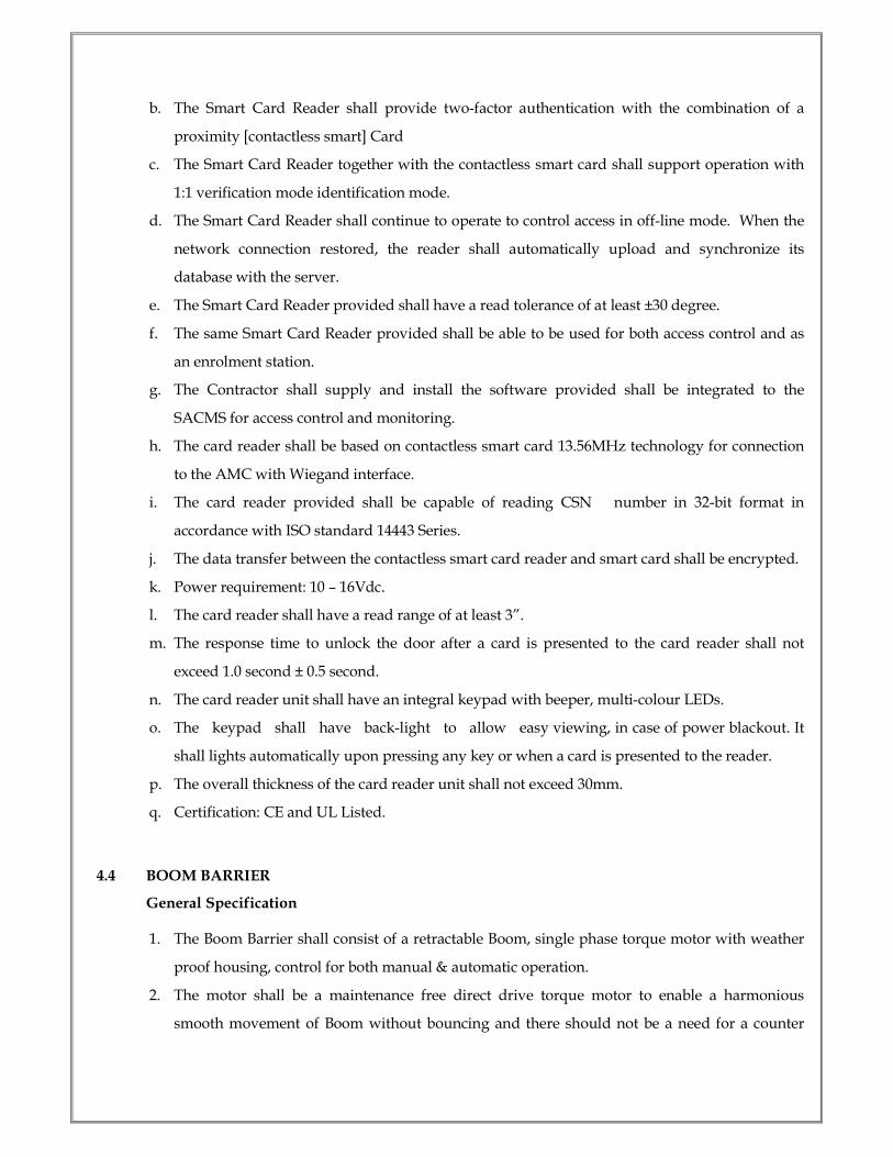
b. The Smart Card Reader shall provide two-factor authentication with the combination of a
proximity [contactless smart] Card
c. The Smart Card Reader together with the contactless smart card shall support operation with
1:1 verification mode identification mode.
d. The Smart Card Reader shall continue to operate to control access in off-line mode. When the
network connection restored, the reader shall automatically upload and synchronize its
database with the server.
e. The Smart Card Reader provided shall have a read tolerance of at least ±30 degree.
f. The same Smart Card Reader provided shall be able to be used for both access control and as
an enrolment station.
g. The Contractor shall supply and install the software provided shall be integrated to the
SACMS for access control and monitoring.
h. The card reader shall be based on contactless smart card 13.56MHz technology for connection
to the AMC with Wiegand interface.
i. The card reader provided shall be capable of reading CSN number in 32-bit format in
accordance with ISO standard 14443 Series.
j. The data transfer between the contactless smart card reader and smart card shall be encrypted.
k. Power requirement: 10 – 16Vdc.
l. The card reader shall have a read range of at least 3”.
m. The response time to unlock the door after a card is presented to the card reader shall not
exceed 1.0 second ± 0.5 second.
n. The card reader unit shall have an integral keypad with beeper, multi-colour LEDs.
o. The keypad shall have back-light to allow easy viewing, in case of power blackout. It
shall lights automatically upon pressing any key or when a card is presented to the reader.
p. The overall thickness of the card reader unit shall not exceed 30mm.
q. Certification: CE and UL Listed.
4.4 BOOM BARRIER
General Specification
1. The Boom Barrier shall consist of a retractable Boom, single phase torque motor with weather
proof housing, control for both manual & automatic operation.
2. The motor shall be a maintenance free direct drive torque motor to enable a harmonious
smooth movement of Boom without bouncing and there should not be a need for a counter
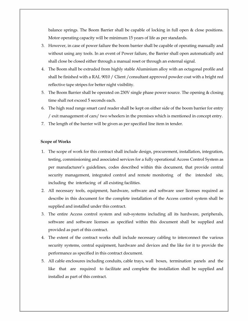
balance springs. The Boom Barrier shall be capable of locking in full open & close positions.
Motor operating capacity will be minimum 15 years of life as per standards.
3. However, in case of power failure the boom barrier shall be capable of operating manually and
without using any tools. In an event of Power failure, the Barrier shall open automatically and
shall close be closed either through a manual reset or through an external signal.
4. The Boom shall be extruded from highly stable Aluminium alloy with an octagonal profile and
shall be finished with a RAL 9010 / Client /consultant approved powder coat with a bright red
reflective tape stripes for better night visibility.
5. The Boom Barrier shall be operated on 230V single phase power source. The opening & closing
time shall not exceed 5 seconds each.
6. The high read range smart card reader shall be kept on either side of the boom barrier for entry
/ exit management of cars/ two wheelers in the premises which is mentioned in concept entry.
7. The length of the barrier will be given as per specified line item in tender.
Scope of Works
1. The scope of work for this contract shall include design, procurement, installation, integration,
testing, commissioning and associated services for a fully operational Access Control System as
per manufacturer’s guidelines, codes described within this document, that provide central
security management, integrated control and remote monitoring of the intended site,
including the interfacing of all existing facilities.
2. All necessary tools, equipment, hardware, software and software user licenses required as
describe in this document for the complete installation of the Access control system shall be
supplied and installed under this contract.
3. The entire Access control system and sub-systems including all its hardware, peripherals,
software and software licenses as specified within this document shall be supplied and
provided as part of this contract.
4. The extent of the contract works shall include necessary cabling to interconnect the various
security systems, central equipment, hardware and devices and the like for it to provide the
performance as specified in this contract document.
5. All cable enclosures including conduits, cable trays, wall boxes, termination panels and the
like that are required to facilitate and complete the installation shall be supplied and
installed as part of this contract.

6. All proposed security field devices installation shall not only to operate functionally, they have
also to blend with the interior design of the building. The contractor shall liaise directly with
the owner, architect, consultant and other services contractor at site in coordination of the
installation work and ensure such requirements are harmonized.
7. All installations carried out by the contractor shall conform to the national standards and code
of practices.
8. The contractor shall cooperate and work closely with site safety officer to ensure safe working
environment at all times.
9. The Contractor shall upon completion of the installation provide complete training with
documentations on the configuration, operation and maintenance of the systems to the
required operators assigned by the Client.
10. All the hardware components under the system covered shall have 24 months of onsite
warranty and the systems shall have antivirus software with facility of offline Updation.
11. The Contractor shall ensure that the Access control system must be expandable in the
following areas:
12. The system shall be designated to allow foreseeable organizational changes and procedural
changes beyond current plans.
13. Additional hardware units shall easily be added without any modification to the existing
hardware, software and network configuration.
Functional Requirements
1. The Access control system shall be SQL based, PC-based system based on Professional
Versions of the latest and viable Windows Operating Systems.
2. The Access control system shall comply to the strict regulation and adapting state-of-the-
art security technologies, the highest level of reliability and integrate to networking
infrastructures such as the Intranet, Internet, LAN/WAN. All interfaces within the Access
control system shall be based on TCP/IP network protocol connectivity over the corporate
intranet/internet/LAN/WAN.
3. The main function of the Access control system shall be to control, monitor and raise alarm of
all designated access to the selected doors, areas or buildings.
4. The Access control system provided shall support industry standards for database, networks,
credential printers, video cameras and more, such as OPC, Auto CAD, HTML, ASPX, and MS-
SQL.
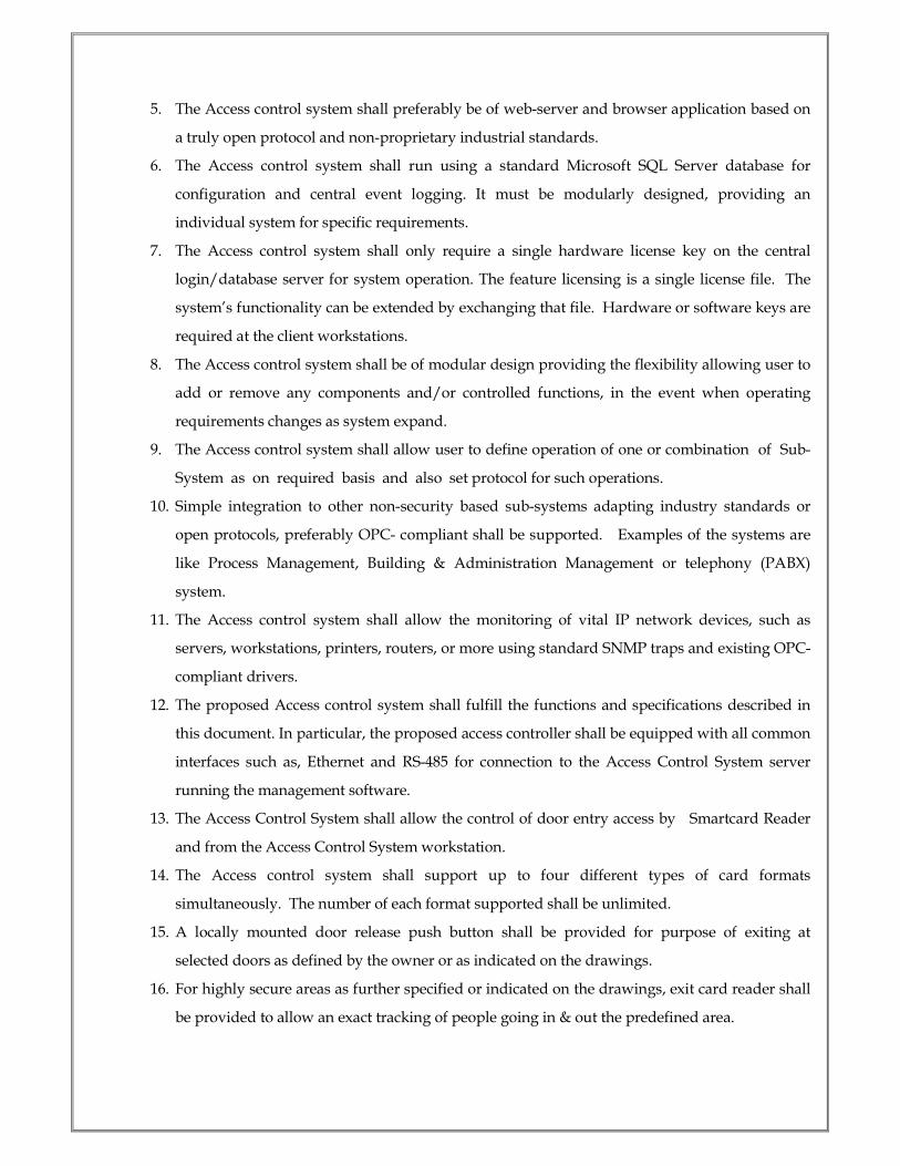
5. The Access control system shall preferably be of web-server and browser application based on
a truly open protocol and non-proprietary industrial standards.
6. The Access control system shall run using a standard Microsoft SQL Server database for
configuration and central event logging. It must be modularly designed, providing an
individual system for specific requirements.
7. The Access control system shall only require a single hardware license key on the central
login/database server for system operation. The feature licensing is a single license file. The
system’s functionality can be extended by exchanging that file. Hardware or software keys are
required at the client workstations.
8. The Access control system shall be of modular design providing the flexibility allowing user to
add or remove any components and/or controlled functions, in the event when operating
requirements changes as system expand.
9. The Access control system shall allow user to define operation of one or combination of Sub-
System as on required basis and also set protocol for such operations.
10. Simple integration to other non-security based sub-systems adapting industry standards or
open protocols, preferably OPC- compliant shall be supported. Examples of the systems are
like Process Management, Building & Administration Management or telephony (PABX)
system.
11. The Access control system shall allow the monitoring of vital IP network devices, such as
servers, workstations, printers, routers, or more using standard SNMP traps and existing OPC-
compliant drivers.
12. The proposed Access control system shall fulfill the functions and specifications described in
this document. In particular, the proposed access controller shall be equipped with all common
interfaces such as, Ethernet and RS-485 for connection to the Access Control System server
running the management software.
13. The Access Control System shall allow the control of door entry access by Smartcard Reader
and from the Access Control System workstation.
14. The Access control system shall support up to four different types of card formats
simultaneously. The number of each format supported shall be unlimited.
15. A locally mounted door release push button shall be provided for purpose of exiting at
selected doors as defined by the owner or as indicated on the drawings.
16. For highly secure areas as further specified or indicated on the drawings, exit card reader shall
be provided to allow an exact tracking of people going in & out the predefined area.

17. In the event of emergency, card holder’s access muster report shall be generated, to provide an
overview of the location where each card holder is in. This allows the security manager to
track the exact and count the number of people within the disaster areas so to assist in the
evacuation.
18. All access doors shall have an emergency break-glass door release installed to unlock the
door for exit in the event of emergency. In addition, all dedicated doors along the escape
route shall automatically open during fire alarm activation.
19. The Access control system shall monitor and record in database all movements and activities at
each control point.
20. The Access control system shall provide configuration and programming of access groups,
where each access group contains a list of control points or access doors to which a card holder
has authorized access.
21. The Access control system shall provide configurable time schedules to have the flexibility for
programming automatic locking and unlocking of any access controlled doors, as well as
activating and de-activating of card holder settings for restricting any access groups from
entering certain areas with the pre-programmed time model.
22. The time schedule shall include holiday facilities to allow user programming for public
holidays and user definable special holidays. All schedules shall be definable by day, hours
and seconds.
23. All other available security subsystems if installed shall be integrated with the Access
control system to form the complete integrated Security Access Control Management System
shall be provided and installed by the Contractor under this contract.
24. The Contractor shall ensure that the system must be expandable and by adding new
component to the existing system will not affect its normal operation.
25. The Access control system design shall allow the security access within the building compound
to be monitored and controlled by the designated security control rooms.
26. There shall be provision for alarm generation whenever there is some attempt to tamper with
the system or some unauthorized intrusion into the system.
27. Reports shall always be readily available and owner shall be able to request for the reports on
exactly what information from the report is required with the use of event filters.
28. The system shall be a flexible and user-friendly workstation providing user(s) with a standard
browser based text and Graphical User Interfaces (GUIs) for alarm monitoring and control.
Such GUIs shall be the core of the entire Access control system that shall interface to all other
available security sub-systems, such as CCTV Surveillance and Recording System, Intrusion

Detection, Public Address System, Visitor Management System, Parking Lot Management,
Explosive and NBC Detection and more as required by the user.
29. The system shall be provided to control access into designated security controlled doors only
by personnel with a valid access card and within valid time schedule. All access cards shall be
authenticated against the central and/or local database before granting access.
30. All door access activities shall be logged into the central database. Any unauthorized attempt
or invalid card used shall be reported to the Access control system, including door held and
forcible entry as priority alarm transactions.
31. With the interface to the CCTV Surveillance System, live images from the camera installed at
the door location shall be displayed at Access control system GUI during door alarm
activation. It shall also be possible to select live view of the camera to view the person’s face
before activating (manually unlocking the door via icon control on the GUI) and granting
during door access request.
32. All equipment within the Access Control System shall continue to operate for at least 2 hours
in the event of main AC power failure. The Contractor shall take in consideration the power
consumption at each point of installation when determining the size of the Uninterrupted
Power Supply (UPS) as backup power. Power backup will be provided by the owner to this
extent.
33. The Access control system provided shall contain all the features and requirements specified,
but not limited to, in this document. The Contractor shall highlight and update the owner of
any new or special functionality that are useful and relevant to the user’s application but not
found in any part of this document.
************
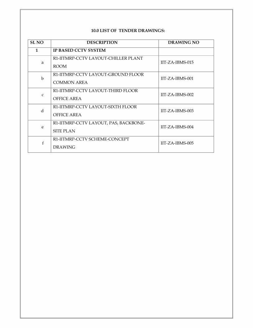
10.0 LIST OF TENDER DRAWINGS:
SL NO DESCRIPTION DRAWING NO
1 IP BASED CCTV SYSTEM
a R1-IITMRP-CCTV LAYOUT-CHILLER PLANT
ROOM IIT-ZA-IBMS-015
b R1-IITMRP-CCTV LAYOUT-GROUND FLOOR
COMMON AREA IIT-ZA-IBMS-001
c R1-IITMRP-CCTV LAYOUT-THIRD FLOOR
OFFICE AREA IIT-ZA-IBMS-002
d R1-IITMRP-CCTV LAYOUT-SIXTH FLOOR
OFFICE AREA IIT-ZA-IBMS-003
e R1-IITMRP-CCTV LAYOUT, PAS, BACKBONE-
SITE PLAN IIT-ZA-IBMS-004
f R1-IITMRP-CCTV SCHEME-CONCEPT
DRAWING IIT-ZA-IBMS-005
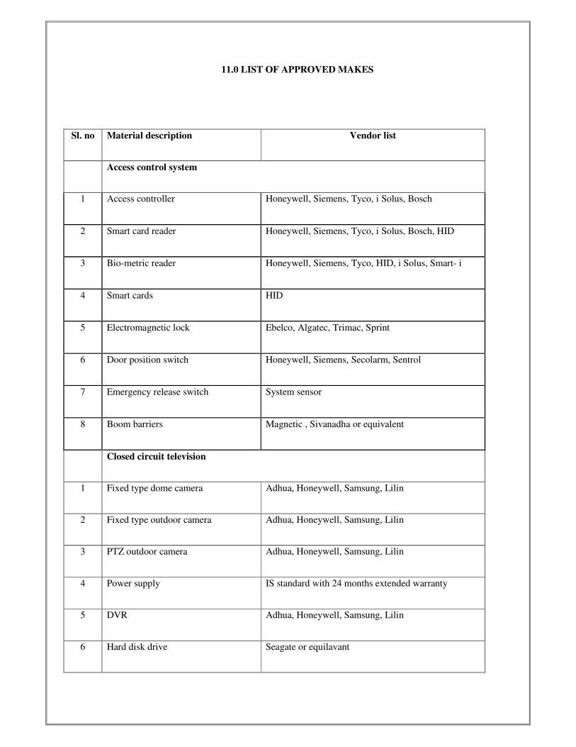
11.0 LIST OF APPROVED MAKES
Sl. no Material description Vendor list
Access control system
1 Access controller Honeywell, Siemens, Tyco, i Solus, Bosch
2 Smart card reader Honeywell, Siemens, Tyco, i Solus, Bosch, HID
3 Bio-metric reader Honeywell, Siemens, Tyco, HID, i Solus, Smart- i
4 Smart cards HID
5 Electromagnetic lock Ebelco, Algatec, Trimac, Sprint
6 Door position switch Honeywell, Siemens, Secolarm, Sentrol
7 Emergency release switch System sensor
8 Boom barriers Magnetic , Sivanadha or equivalent
Closed circuit television
1 Fixed type dome camera Adhua, Honeywell, Samsung, Lilin
2 Fixed type outdoor camera Adhua, Honeywell, Samsung, Lilin
3 PTZ outdoor camera Adhua, Honeywell, Samsung, Lilin
4 Power supply IS standard with 24 months extended warranty
5 DVR Adhua, Honeywell, Samsung, Lilin
6 Hard disk drive Seagate or equilavant
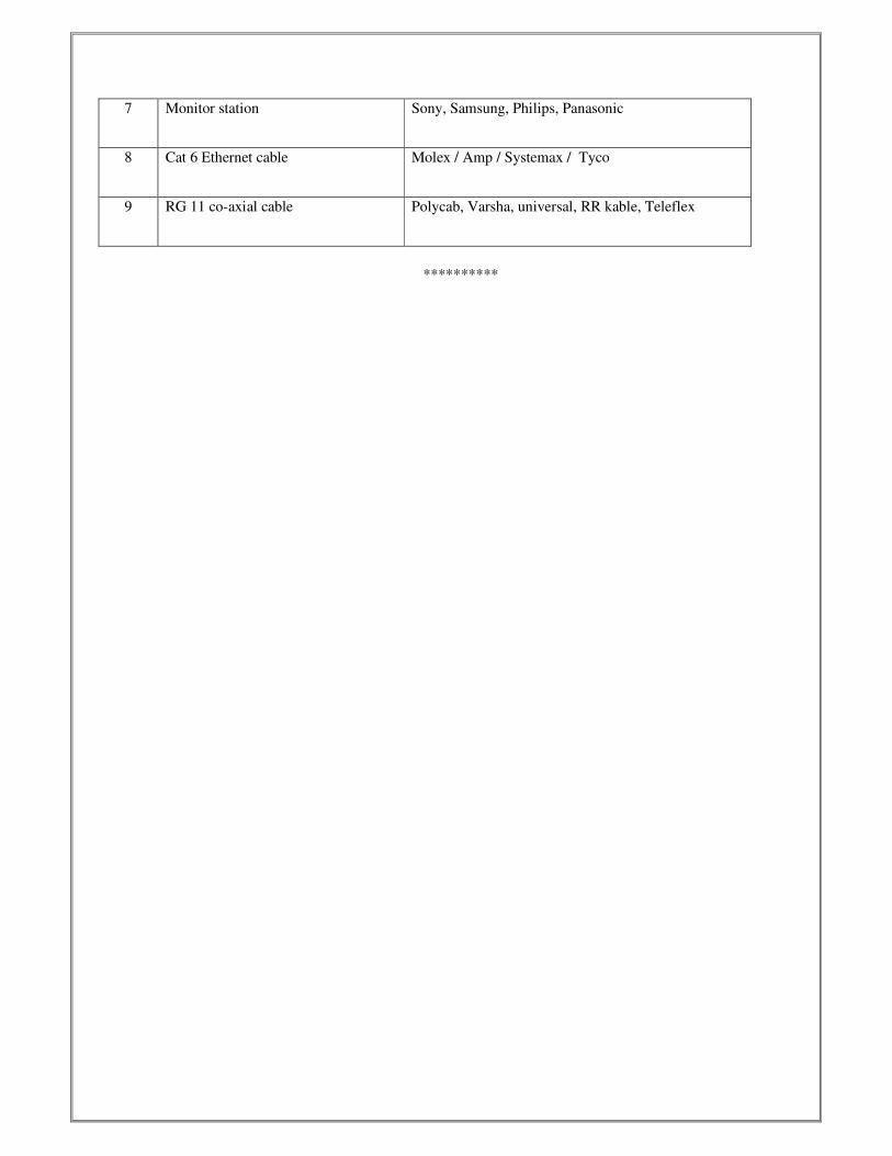
7 Monitor station Sony, Samsung, Philips, Panasonic
8 Cat 6 Ethernet cable Molex / Amp / Systemax / Tyco
9 RG 11 co-axial cable Polycab, Varsha, universal, RR kable, Teleflex
**********


![INDEX [agora.mfa.gr] documents...specification CE/416/CCTV/DVC-DeNox for DVC Mejia TPS Unit 7&8 2X500MW project 1 Set 2 PR0900000137 IP CCTV System - IP BASED CLOSE CIRCUIT TELEVISION](https://img.pdfslide.us/doc/110x75/5e78c5b43af94e42be24e28a/index-agoramfagr-documents-specification-ce416cctvdvc-denox-for-dvc-mejia.jpg)