Embed Size (px)
Citation preview
AD-A286 627 MIL-STD-1 540C
O I~I~I~I~LI I!~i~ II15 SEPTEMBER 1994SupersedingMIL-STD-1540B (USAF)10 OCTOBER 1982
MILITARY STANDARD
TEST REQUIREMENTSFOR
LAUNCH, UPPER-STAGE, AND SPACE VEHICLES
-Accesiorn ForNTIS CRAMI
DTIC TABUnannounced LJ
Justification
ByICDiýt. ibL~ion I
Aie v .tb: . " \/ 2 31994
Dist
""S )Ž94.35939
AMSC NIA FSC 1810
DISTRIBUTION •TATIMNT A Approved for public release; distribution is unlimited.
Reproduced FromBest Available Copy K " v ,
MIL-STD- 1 540C
FOREWORD
1. This Military Standard is approved for use by all Departments and Agencies of theDepartment of Defense.
2. Beneficial comments (recommendations, additions, or deletions) and any pertinentdata which may be of use in improving this document should be provided by usingthe self-addressed Standardization Document Improvement Proposal (DO Form1426). appearing at the end of this document, or by letter addressed to:
Space "nd Missile Systems Center, SMC/SDFP160 Skynet Street, Suirte 2315Los Angeles AFB, CA 90245.4683
3. A successful on-orbit system means that an flight vehicles (launch, upper-stage.space), computer software, ground equipment, faclhties, procedures. and peopleoperate properly and in a timely way. Extensive testing at every level of assemblyhas been cost effective in assuring successful hardware and software designs andoperations. As a cornerstone of this activity, this Standard establishes theenvironmental and structural ground testing requirements of flight vehicles, end oftheir associated subsystems and units. In addition, this Standard establishes auniform set of definitions of related terms.
A. To supplement these requirements, other areas of the testing baseline required formission success are addressed in other documents. Typical test requirements forparts, materials, and processes are in their detailed specifications. Typical testrequirements for the applical:e ground equipment and associated computersoftware are outlined in MIL-STD- 1833. These tests include integrated systemtests (Step 3 tests), and operational tests (Step 4 and Step 5 tests). Computersoftware test requirements are also addressed in DOD-STD-2167.
5. As described in this Standard, the formal compliance tests for flight vehicleequipment start at the unit level of assembly and progress at each higher level ofassembly until the entire launch system and the on-orbit system can be tested intheir operational configurations. In addition, there may be development tests andevaluations nt various levels of esembly, end in-process inspections and tests toavoid assembling a defective system. The formal compliance tests addressed inthis document are qualification and acceptance at the unit, subsystem, andvehicle level as well a some of the integrated system prelaunch validatioft tests.The integrated system prelaunch validation test requirements addressed areIntended to be combined with or incorporated with the MIL-STD-1833 Step 3, 4.and 5 teats that include the applicable ground equipment and associated compstirsoftwwar.

PAGES______ARE
MISSINGIN
ORIGINALDOCUMENT
MIL-STD-1 540C
TABLE OF CONTENTS(continued)
page
4.9 DOCUMENTATION ...................................... 224.9.1 Test Documentation Files . ........................... 224.9.2 Test Data . ...................................... 224.9.3 Test Log . ....................................... 22
5 DEVELOPMENT TESTS ....................................... 23
5.1 GENERAL ... ......................................... 235.2 PART, MATERIAL. AND PROCESS DEVELOPMENT TESTS
AND EVALUATIONS ................................... 245.3 SUBASSEMBLY DEVELOPMENT TESTS, IN-PROCESS TESTS
AND INSPECTIONS . .................................. 245.4 UNIT DEVELOPMENT TESTS .............................. 245.4.1 Structural Composite Development Tests ................ 255.4.2 Thermal Development Tests .......................... 255.4.3 Shock and Vibration Isclator Development Thsts ........... 265.5 VEHICLE AND SUBSYSTEM DEVELOPMENT TESTS ............. 265.5.1 Mechanical Fit Development Tests . ..................... 265.5.2 Mode Survey Development Tests ...................... 265.5.3 Structural Development Tests ........................ 265.5.4 Acoustic and Shock Development Tests ................. 275.5.5 Thermal Balance Development Tests .................... 275.5.6 Transportation and Handling Development Tests ........... 285.5.7 Wind-tunnel Development Tests.. ....................... 28
* QUAUFICATION TESTS . .................................... 30
6.1 GENERAL QUALIFICATION TEST REQUIREMENTS .............. 306.1.1 Qualification Hardware ............................. 306.1.2 Qualification Test Levels and Durations .................. 306.1.3 Thermal Vacuum and Thermal Cycle Tests ............... 318.1.4 Acoustic and Vibration Qualification .................... 326.2 VEHICLE QUALIFICATION TESTS .......................... 356.2.1 Functional Test, Vehicle Qualification .................... 366.2.2 Electromagnetic Compatibility Test, Vehicle Qualification ..... 376.2.3 Shock Test, Vehicle Qualification ...................... 386.2.4 Acoustic Teat, Vehicle Qualification .................... 396.2.5 Vibration Test, Vehicle Qualification .................... 406.2.6 Pressure and Leakage Tests, Vehicle Qualification .......... 416.2.7 Thermal Cycle Test, Vehicle Qualification ................ 428.2.8 Thermal Balance Test, Vehicle Qualification ............... 436.2.9 Thermal Vacuum Test, Vehicle Qualification .............. 450.2.10 Mode Survey Test, Vehicle Qualification . ............... .466.3 SUBSYSTEM QUAUFICATION TESTS ...................... 486.3.1 Structural Static Load Test, Subsystew,- Qualification ........ 49
V
MIL-STD-1 540C
TABLE OF CONTENTS(continued) page 1
0.3.2 Vibration Test, Subsystem Qualification ... ................ 516.3.3 Acoustic Test, Subsystem Qualification ................. 516.3.4 Thermal Vacuum Test. Subsystem Qualification ............ 516.3.5 Separation Test, Subsystem Qualification ................ 526.4 UNIT QUALIFICATION TESTS ............................ 536.4.1 Functional Test. Unit Qualification ..................... 536.4.2 Thermal Cycle Test. Electrical and Electronic Unit Qualification. 556.4.3 Thermal Vacuum Test, Unit Qualification ................. 576.4.4 V'ibration Test. Unit Qualification ................... .. 600.4.5 Acoustic Test. Unit Qualification ...................... 62F,.4.6 Shock Test, Unit Qualification ........................ 626.4.7 Leakage Test, Unit Qualification ....................... 646.4.8 Pressure Test, Unit Qualification .. ..................... 646.4.9 Acceleration Test, Unit Qualification .................... 666.4.10 Life Test, Uni: Qualification ....................... ... 666.4.11 Electromagnetic Compatibility (EMC) Test. Unit Qualification ... 686.4.12 Climatic Tests. Unit Qualification ...................... 686.4.12.1 Purpose, Climatic Tests, Unit Qualification ............ 686.4.12.2 Humidity Test, Unit Qualification .................. 636.4.12.3 Sand and Dust Test, Unit Qualification .............. 706.4.12.4 Rain Test, Unit Qualification ...................... 716.4.12.5 Salt Fog Test, Unit Qualification ................... 716.4.12.6 Explosive Atmosphere Test, Unit Qualification ......... 71
7 ACCEPTANCE TESTS ...................................... 72
7.1 GENERAL ACCEPTANCE TEST REQUIREMENTS ............... 727.1.1 Temperature Range and Number of Thermal Cycles,
Acceptance Tests ................................ 727.1.2 Acoustic Environment, Acceptance Tests .......... 757.1.3 Vibration Environment. Acceptance Tests ................ 757.1.4 Storage Tests: Vehicle. Subsystem, or Unit Acceptance ...... 757.2 VEHICLE ACCEPTANCE TESTS .......................... 757.2.1 Functional Test, Vehicle Acceptance .................... 757.2.2 Electromagnetic Compatibility (EMC) Test, Vehicle Acceptance . 807.2.3 Shock Test, Vehicle Acceptance ...................... 807.2.4 Acoustic Test, Vehicle Acceptance ..................... 807.2.5 Vibration Test. Vehicle Acceptance .................... 817.2.0 Pressure and Leakage Test, Vehicle Acceptance ............ 817.2.7 Thermal Cycle Test, Vehicle Acceptance ................. 827.2.8 Thermal Vacuum Test, Vehicle Acceptance ............... 827.3 SUBSYSTEM ACCEPTANCE TESTS ........................ 837.3.1 Proof Load Test, Structural Subsystem Acceptance .......... 837.3.2 Proof Prestsure Test, Pressurized Subsystem Acceptance ...... 84
vi
MIL-STD-1 540C
TABLE OF CONTENTS(continued)
Q page
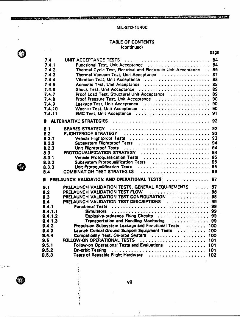
7.4 UNIT ACCEPTANCE TESTS ............................... 847.4.1 Functional Test, Unit Acceptance . ...................... 847.4.2 Thermal Cycle Test, Electrical and Electronic Unit Acceptance .. 867.4.3 Thermal Vacuum Test, Unit Acceptance ................. 877.4.4 Vibration Test, Unit Acceptance . ....................... 887.4.5 Acoustic Test, Unit Acceptance . ....................... 887.4.6 Shock Test, Unit Acceptance . ......................... 897.4.7 Proof Load Test, Structural Unit Acceptance .............. 897.4.8 Proof Pressure Test, Unit Acceptance . ................... 907.4.9 Leakage Test, Unit Acceptance ....................... 907.4.10 WeEr-in Test, Unit Acceptance . ........................ 907.4.11 EMC Test, Unit Acceptance . .......................... 91
8 ALTERNATIVE STRATEGIES .................. ...... ........ 928.1 SPARES STRATEGY ............ ................ 92
.8.2 FLIGHTPROOF STRATEGY ....... ..................... 938.2.1 Vehicle Flightproof Tests.. ............................ 938.2.2 Subsystem Flightproof Tests ......................... 948.2.3 Unit Flightproof Tests . .............................. 948.3 PROTOQUALIFICATION STRATEGY ......................... 948.3.1 Vehicle Protoqualification Tests . ....................... 958.3.2 Subsystem Protoqualification Tests .... ................ 958.3.3 Unit ProtoqualifIcation Tests. ......... ................. 958.4 COMBINATION TEST STRATEGIES ........ ................ 96
9 PRELAUNCH VALIDA'0ON AND OPERATIONAL TESTS ............... 97
9.1 PRELAUNCH VALIDATION TESTS, GENERAL REQUIREMEN!S ..... 979.2 PRELAUNCH VALIDATION TEST FLOW ..................... 989.3 PRELAUNCH VALIDATION TEST CONFIGURATION ............. 989.4 PRELAUNCH VALIDATION TEST DESCRIPTIONS ................ 999.4.1 Functional Tests .................................. 999.4.1.1 Simuuators .................................. 999.4.1.2 Explosive-ordnance Firing Crcuits. 999.4.1.3 Transportation and Handling Monitoring ............. 999.4.2 Propulsion Subsystem Leakage and Functional Tests ....... 1009.4.3 Launch Critical Ground Support Equipment Tests .......... 1009.4.4 Compatibility Test, On-orbit System .................... 1009.5 FOLLOW-ON OPERATIONAL TESTS ........................ 1019.5.1 Follow-on Operational Tests and Evaluations ............. 1019.5.2 On-orbit Testing ................................. 1019.5.3 Tests of Reusable Flight Hardware .................... 102
.vii
A
MIL-STD-1 540C
TABLE OF CONTENTS(continued)0
page
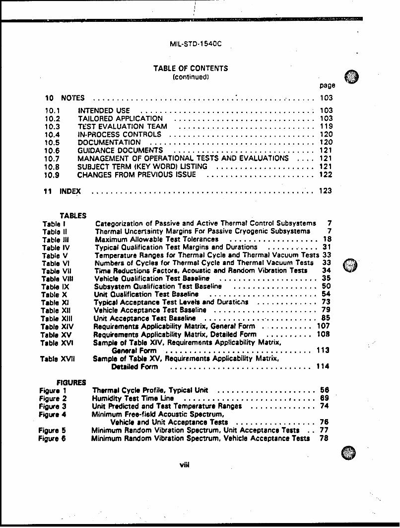
10 NOTES................................. *................. 103
10.1 INTENDED USE........................................ 10310.2 TAILORED APPLICATION................................. 10310.3 TEST EVALUATION TEAM................................ 11910.4 IN-PROCESS CONTROLS.................................. 12010.5 DOCUMENTATION...................................... 12010.6 GUIDANCE DOCUMENTS......................12110.7 MANAGEMENT OF OPERATIONAL iiTESTS AND E*V, A L*UAT'IO0NS* . 12110.8 SUBJECT TERM (KEY WORD) LISTING........................ 12110.9 CHANGES FROM PREVIOUS ISSUE.......................... 122
11 INDEX................................................... 123
TABLESTable I Categorization of Passive and Active Thermal Control Subsystems 7Table 11 Thermal Uncertainty Margins For Passive Cryogenic Subsystems 7Table Ill Maximum Allowable Test Tolerances...................... 18Table IV Typical Qualification Test Margins and Durations..............31Table V Temperature Ranges for Thermal Cycle and Thermal Vacuum Tests 33Table VI Numbers of Cycles for Thermal Cycle and Thermal Vacuum Tests 33 (Table VII Time Reductions Factors, Acoustic and Random Vibration Tests 34 4Table ViII Vehicle Qualification Test Baseline........................ 35Table IX Subsystem Qualification Test Baseline..................... 50Table X Unit Qualification Test Baseline...........................54Table Xl Typical Acceptance Test Levels and Duratic.,s............... 73Table XII Vehicle Acceptance Test Baseline........................ 79Table XI1I Unit Ac'ceptance Test Baseline........................... 85Table XIV Requirements Applicability Matrix, General Form.............107Table XV Requirements Applicability Matrix, Detailed Form.............108Table XVI Sample of Table XIV. Requirements Applicability Matrix.
General Form.................................113Table XVII Sample of Table XV. Requirements Applicability Matrix,
Detailed Form................................ 114
FIGURESFigure 1 Thermal Cycle Profile, Typical Unit.......................56Figure 2 Humidity Test rime Une.......................... ,..... 69Figure 3 Unit Predicted and Test Temperature Ranges................ 74Figure 4 Minimum Free-field Acoustic Spectrum.
Vehicle and Unit Acceptance Tests................... 76Figure 5 Minimum Random Vibration Spectrum. Unit Acceptance Tests .. 77Figure 6 Minimum Random Vibration Spectrum, Vehicle Acceptance Tests 78
Vill
MIL-STD-1 540C
SECTION 1
SCOPE
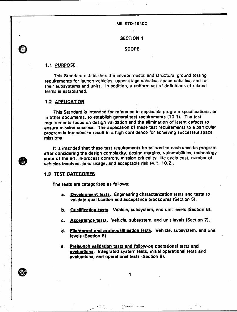
1.1 pURPOSE
This Standard establishes the environmental and structural ground testingrequirements for launch vehicles, upper-stage vehicles, space vehicles, end fortheir subsystems and units. In addition, a uniform set of definitions of relatedterms is established.
1.2 AEPLICATIOJN
This Standard is intended for reference in applicable program specifications, orin other documents, to establish general test requirements (10.1). The testrequirements focus on design validation and the elimination of latent defects toensure mission success. The application of these test requirements to a particularprogram Is intended to result In a high confidence for achieving successful spacemissions.
It Is Intended that these test requirements be tailored to each specific programafter considering the design complexity, design margins, vulnerabilities, technologystate of the art, in-process controls, mission criticality, life cycle cost, number ofvehicles involved, prior usage, and acceptable risk (4.1, 10.2).
1.3 TEST CATEGORIES
The tests are categorized as follows:
a. DOvlobment tests. Engineering characterization tests and tests tovalidate qualification and acceptance procedures (Section 5).
b. Quallflcatlon tests. Vehicle, subsystem, and unit levels (Section 6).
c. Acceotsnce test,. Vehicle, subsystem, and unit levels (Section 7).
d. FlIghtroof and Rrotocuaflflcatlon tests. Vehicle, subsystem, and unitlevels (Section 8).
a. Prelaunch validation tests and foflow-on ooeratlonal tests and.axlutlj•I. Integrated system tests, initial operational temts and
evaluations, and operational tests (Section 9).
0I
MIL-STD-1 540C
SECTION 2
APPLICABLE DOCUMENTS
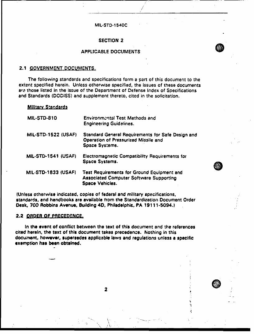
2.1 GOVERNMENT DOCUMENTS.
The following standards and specifications form a part of this document to theextent specified herein. Unless otherwise specified, the issues of these documentsarc those listed in the issue of the Department of Defense Index of Specificationsand Standards (DODISS) and supplement thereto, cited in the solicitation.
Military Standards
MIL-STD-810 Environm,,ntal Test Methods andEngineering Guidelines.
MIL-STD-1522 (USAF) Standard General Requirements for Safe Design andOperation of Pressurized Missile andSpace Systems.
MIL.STD-1541 (USAF) Electromagne:ic Compatibility Requirements forSpbce Systems.
MIL-STD-1833 (USAF) Test Requirements for Ground Equipment andAssociated Computer Software SupportingSpace Vehicles.
(Unless otherwise indicated, copies of federal and military specifications,standards, and handbooks are available from the Standardization Document OrderDesk, 700 Robbins Avenue, Building 4D, Philadelphia, PA 19111-5094.)
2.2 ORDER OF PRECEDENCE.
In the event of conflict between the text of this document and the referencescited herein, the text of this document takes precedence. Nothing in thisdocument, however, supersedes applicable laws and regulations unless a specificexemption has beon obtained.
2 , 1
MIL-STD-1 540C
SECTION 3
0 DEFINITIONS
3.1 ITEMEYELL.
The categories of items in hierarchical order are defined in this section.
3.1.1 Prt. A part is a single piece, or two or more joined pieces, which arenot normally subject to disassembly without destruction or impairment of thedesign use. Examples: resistor, integrated circuit, relay, roller bearing.
3.1.2 Subasm•mby•. A subassembly is a unit containing two or more partswhich Is capable of disassembly or part replacement. Examples: printed circuitboard with parts installed, gear train.
3.1.3 Uni=. A unit is a functional item that is viewed as a complete andseparate entity for purposes of manufacturing, maintenance, or record keeping.Examples: hydraulic actuator, valve, battory, electrical harness, transmitter.
3.1.4 Subsyutem. A subsystem is an assembly of functionally related units.It consists of two or more units and may include interconnection items such ascables or tubing, and the supporting structure to which they are mounted.Examples: electrical power, attitude control, telemetry, thermal control, andpropulsion subsystems.
3.1.5 Vehicia. Any vehicle defined in this section may be termed expendableor recoverable, as appropriate.
3.1.5.1 Lautnch Vehicle. A launch vehicle is one or more of tha lower stagesof a flight vehicie capable of launching upper-stage vehicles and space vehicles,usually Into a suborbital trajectory. A fairing to protect the space vehicle, andpossibly the upper-stage vehicle, during the boost phase is typically considered tobe part of the launch vehicle.
3.1.5.2 LUpcer-stage Vehicle. An upper-stage vehicle is one or more stages ofa flight vehicle capable of injecting a space vehicle or vahicles into orbit from thesuborbital trajectory that resulted from operation of a launch vehicle.
3.1.5.3 Space Exporlment. A space experiment is itsually part of the spacevehicle payload and is therefore considered to be a lower level assembly of a spacevehicle. However, a space experiment may be an Integral part of a space vehicle,a payload that performs its mission while attached to a space vehicle, or even apayload that Is carried by a host vehicle but performs some of its mission as afree-flyer. Whether complex space equipment Is called a space experiment, a
3
,,- -
MIL-STD-1 540C
space instrument, or a space vehicle is discretionary and the nomenclature usedshould not affect the classification of the equipment or the requirements.
3.1.5.4 Spc Veice A space vehicle is an integra~ted set of subsystemsand units capable of supporting an operational role in space. A space vehicle maybe an orbiting vehicle, a major portion of an orbiting vehicle, or a payload whichperforms its mission while attached to a launch or Lipper-stage vehicle. Theairborne support equipment (3.2.1), which is peculiar to programs utilizing arecoverable launch or upper-stage vehicle, is considered to be a part of the spacevehicle.
3.1.5.5 Flight Vehigl. A flight vehicle is the combination of elements of thelaunch system that is flown; i.e.. the launch vehicle(s), the upper-stage vehicle(s),and the space vehicle(s) to be sent to orbit.
3.1.6 Sytm A system is a composite of equipment, skills, and techniquescapable of performing or supporting an operational role. A system includes alloperational equipment, related facilities, material, software, services, and personnelrequired for Its operation. A system is typically defined by the System ProgramOffice or the procurement agancy responsible for its acquisition.
3.1.7 Combined Siystems. Combined systems are Interconnected systemsthat are required for program level operations or operational tests. The combinedsystems of interest are typically the launch system and the on-orbit system.
3.1.7.1 Lanchjnb.System. A launch system is the composite of equipment,skills, and techniques capable of launching and boosting one or more spacevehicles into orbit. The launch system Includes the flight vehicle and relatedfacilities, ground equipment, material, software, procedLres, services, andpersonnel required for their operation.
3.1.7.2 On-orbit System. An on-orbit system Is the composite of equipment,skills, and tec'iniques permitting on-orbit operation of the space vehicle(s). Theon-orbit system includes the space vehicle(s), the command and control network,and related facilities, ground equipment, material, software, procedures, services,and personnel required for their operation.
3.2.1 Alrborne SURoort Eguloment (ASE). Airborne support equipment is theequipment installed in a flight vehicle to provide support functions and interfacesfor the space or upper-stage vehicle during launch and orbital operations of theflight vehicle. This includes the hardware and software that provides thestructural, electrical, electronic, and mechanical interfaces with the flight vehicle.
4
MIL-STD-1540C
3.2.2 CriticaLL nii. A critical unit is one whose failure can affect the systemoperation sufficiently to cause the loss of the stated vehicle objectives, a partialloss of the mission, or is a unit whose proper performance is essential from a rangesafety standpoint.
3.2.3 Develooment Test Article. A development test article is arepresentative vehicle, subsystem, or unit dedicated to provide design and testinformation. The information may be used to check the validity of analytictechniques and assumed design parameters, to uncover unexpected responsecharacteristics, to evaluate design changes, to determine interface compatibility, toprove qualification and acceptance test procedures and techniques, or to determineif the equipment meets its performance specifications. Development test articlesinclude engineering test models, thermal models, and structural static and dynamicmodels.
3.2.4 Egj~oIMardnance Device. An explosive-ordnance device is a devicethat contains or is operated by explosives. A cartridcge-actuated device, one typeof explosive-ordnance device, is a mechanism that employs the energy producedby an explosive charge to perform or initiate a mechanical action.
3.2.5 Moving Mechanical Assembly (MMAI. A moving mechanical assemblyis a mechanical or electromechanical device that controls the movement of onemechanical part of a vehicle relative to another part. Examples: gimbals, actuators,despin and separation mechanisms, valves, pumps, motors, latches, clutches,springs, dampers, bearinqs.
3.2.6 Reusableem. A reusable item is a unit, subsystem, or vehicle that isto be used for multiple missions. The service life (3.5.6) of reusable hardwareincludes all planned reuses, refurbishment, and retesting.
3.3 ENVIRONMENTS
The complex flight environment involves a combination of conditions that areusually resolved into individual test environments. Each test environment shouldbe based on actual flight data, scaled if necessary for differences in parameters, orif more reliable, by analytical prediction or a combination of analysis and flightdata. The flight data may be from the current flight system, or from other flightsystems if configuration variations are accounted for and properly scaled. TheIndividual environments, which may be involved in qualification and acceptance,are described in this section.
3.3.1 Maximum and Minimum Expected Temoiratur2 . The maximum andminimum expected temperatures are the highest and lowest temperatures that anitem can experience during Its service life (3.5.6), Including all operational modes.These temperatures are established from analytically determined extremotemperatures by adding a thermal uncertainty margin, discussed below. The
51
4.
MIL-STD-1540C
analytically determined extreme temperatures are predicted from thermal modelsusing applicable effects of worst-case combinations of equipment operation,internal heating, vehicle orientation, solar radiation, eclipse conditions, ascentheating, descent heating, and degradation of thermal surfaces during the servicelife.
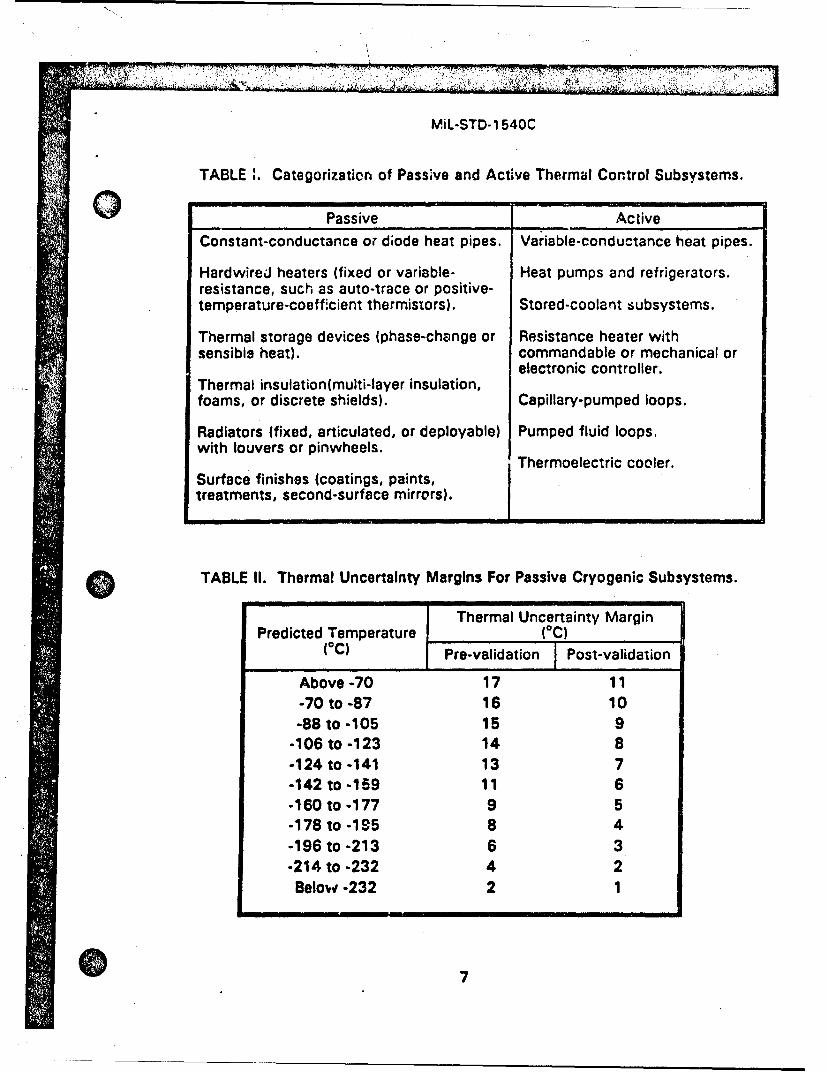
For space and upper-stage vehicles, the analytical model is validated usingresults from a vehicle thermal balance test involving operational modes whichinclude the worst-case hot and cold conditions. The thermal uncertainty margin iscpplied to the analytically determined extreme temperatures, even after validationby a thermal balance test. The thermal uncertainty margin accounts foruncertainties in parameters such as complicated view factors, surface properties,rrziation environment, joint conduction, and unrealistic aspects of ground testsimulation. The margins vary depending on whether passive or active thermalcontrol techniques are used. Examples of each type, for purposes of uncertaintymargin to be applied, appear in Table I. The margins to be applied are addressed inthe following subparagraphs.
3.3.1.1 Maralns for Passive Thermal Control Subsystems. For units that haveno thermal control or have only passive thermal control, the recommendedminimum thermal uncertainty margin is 17*C prior to achieving a val'datedanalytical modc. F-ir space and upper-stage vehicles, the uncertainty margin maybe reduced to 11"C after the analytical model is validated using results from avehicle thermal balance test. To avoid significant weight and power increases ofthe power subsystem due to additional hardware or increased heater size, theuncertainty margin of 1 70C may be reduced to 11 °C.
For units that have large uncertainties in operational or environmentalconditions or that do not require thermal balance testing, the thermal uncertaintymargin may be greater than those stated above. Examples of these units for alaunch vehicle are a vehicle heat shield, external insulation, and units within the aftskirt.
For passive cryogenic subsystsms operating below minus 700C, the thermaluncertainty margin may be reduced as presented in Table II. In addition, thefollowing thermal-uncertainty heat-load margins are recommended: 50 percent inthe conceptual phase, 45 percent for preliminary design, 35 percent for criticaldesign review, and 30 percent for qualification.
3.3.1.2 Marglns for Active Thermal Control Subsystems. For thermal designsin which temperatures are activeiy controlled, a heat-load margin of 25 percentmay be used in lieu of the thermal margins specified in 3.3.1.1. This margin isapplicable at the condition that Imposes the maximum and minimum expectedtemperatur-3. For example, for heaters regulated by a mechanical thermostat orelectronic controller, a 25-percent heater capacity margin may be used In lieu ofthe thormal margins at the minimum expected temperature and at minimum bus
6
MIL-STD-1 540C
TABLE C.Categorization of Passive and Active Thermal Control Subsystems.
Passive Active
Constant-conductance or diode heat pipes. Variable-conductance heat pipes.
HardwireJ heaters (fixed or variable- Heat pumps and refrigerators.resistance, such as auto-trace or positive-temperature-coefficient thermistors). Stored-coolant subsystems.
Thermal storage devices (phase-change or Resistance heater withsensible heat). commandable or mechanical or
electronic controller.Thermal insulation(multi-layer insulation,foams, or discrete shields). Capillary-pumped loops.
Radiators (fixed, articulated, or deployable) Pumped fluid loops.with louvers or pinwheels.
Thermoelectric cooler.Surface finishes (coatings, paints,treatments, second-surface mirrors).
TABLE II. Thermal Uncertainty Margins For Passive Cryogenic Subsystems.
Thermal Uncertainty MarginPredicted Temperature (°C)
(OC) Pre-validation Post-validation
Above-70 17 11-70 to -87 16 10
-88 to -105 15 9-106 to -123 14 8-124 to -141 13 7-142 to -159 11 6-160 to -177 9 5-178 to -195 8 4-196 to -213 6 3-214 to -232 4 2Below -232 2 1
7
MIL-STD-1540C
voltage, which translates into a duty cycle of no more than 80 percent under thesecold conditions. Where an 11 0C addition in the analytically determined extremetemperatures would cause the temperature of any part of the actively-controlled 0unit to exceed an acceptable temperature limit, a control-a.uthority margin in excessof 25 percent should be demonstrated.
For designs In which the temperatures are actively controlled to below minus70'C by expendable coolants or refrigerators, the thermal uncertainty heat-loadmargin of 25 percent should be increased in the early phases of the development.For these cases, the following thermal-uncertainty heat-load margins arerecommended: 50 percent in the conceptual phase, 45 percent for preliminarydesign, 35 percent for the critical design review, and 30 percent for Qualification.
3.3.2 Statisttcal Estimates of Vibration. Acoustic. and Shock Environmerls.Qualification and acceptance tests for vibration, acoustic, and shock environmentsare based upon statistically expected spectral levels. The level of the extremeexpected environment, used for qualification testing, is that not exceeded on rtleast 99 percent of flights, estimated with 90-percent confidence (P99/90 level).The level of the maximum expected environment, used for acceptance testing, isthat not exceeded on at least 95 percent of flights, estimated with 50-percentconfidence (P95/50 level). These statistical estimates are made assuming alognormal flight-to-flight variability having a standard deviation of 3 de, unless adifferent assumption can be justified. As a result, the P95/50 level estimate is 5dB above the estimated mean (namely, the average of the logarithmic values of thespectral levels of data from all available flights). When data from N flights are usedfor the estimate, the P99/90 estimate in dB is 2.0 + 3.9/N1 2 above the P95/50estimate. When data from only one flight are available, those data are assumed torepresent the mean and so the P95/50 is 5 dB higher and the P99/90 level is 11dB higher.
When ground testing produces the realistic flight environment (for example,engine operation or activation of explosive ordnance), the statistical distributioncan be determined using the test data, oroviding data from a sufficient number oftests are available. The P99/90 and P95/50 levels are then determined from thederived distribution.
Extreme and maximum expected spectra should be specified for zones of thelaunch, upper-stage, and space vehicles to allow for repositioning of units withintheir zones without changing the expected environment. Particular spectra can bedeveloped for specific units.
3.3.3 Fatloue Eoulvalent Duration. For a time-varying flight acoustic orvibration environment, tha fAtigue equivalent duration is the time duration, at themaximum envircnment achieved during that flight, that would produce the samefatigue damage potential. For a given flight trajectory, the equivalent duration canbe assumed to be independent of the maximum environment achieved during any
MIL-STD- 1 540C
particular flight. The fatigue damage potential is taken to be proportional to theAM fourth power of amplitude, unless another basis can be justified.
3.3.4 Extreme and Maximum Expected Acoustlc Environment. The acousticenvironment for an exterior or interior zone of a vehicle results from propulsive andaerodynamic excitations. The acou3tic environment is expressed by a1/3-octave-band pressure spectrum in dB (reference 20 micropascal) for centerfrequencies spanning a range of at least 31 to 10,000 Hz. For a time-varyingenvironment, the acoustic spectrum used for test purposes is the envelope of thespectra for each of a series of 1-second time segments overlapped by at least 50percent. Longer time segments may be used only if it is shown that significantsmoothing of the time-dependent characteristics of the spectra (that is, large biaserror) does not occur. The extreme and maximum expected acoustic environments(P99/90 and P95/50 acoustic spectra, respectively, per 3.3.2) are the bases forqualification and acceptance test spectra, respectively, subject toworkmanship-based minimum spectra. The aszociated duration is the fatigueequivalent duration in flight (3.3.31.
3.3.5 Extreme and Maximum Exnected Random Vibration Environment. Therandom vibration environment induced at the structural attachments of units is dueto the direct or indirect action of the acoustic and aerodynamic excitations, toroughness In combustion or burning processes, and to machinery induced randomdisturbances. The random vibration environment is expressed as an accelerationspectral density in g2/Hz (commonly termed power spectral density or simply PSD)over the frequency range of at least 20 to 2000 Hz. For a time-varyingenvironment, the PSD used for test purposes is the envelope of the spectra foreach of a series of 1-second time segments overlapped by at least 50 percent.Longer time segments may be used only If it Is shown that significant smoothing ofthe time-dependent characteristics of the spectra (that is, large bias error) does notoccur. Also, the resolution bandwidth is to be no greater than 1/6 octave, butneed not be less than 5 Hz. The extreme and maximum expected vibrationenvironments (P99/90 and P95/50 PSOs, respectively, per 3.3.2) are the bases forthe qualification and acceptance test spectra, respectively, subject toworkmanship-based minimum spectra. The associated duration is the fatigueequivalent duration in flight (3.3.3).
3.3.6 Extame and Maximum Expected Silnusoldal Vibration Environment. Thesinusoidal vibration Induced at the structural attachments of units may be due tcperiodic excitations from rotating machinery and from Instability involving pogo(interaction of structural and propulsion dynamics), flutter (interaction of structuraldynamics and aerodynamics), or combustion. Periodic excitations may also occurduring ground transportation. The sinusoidal vibration environment is expressed asan acceleration amplitude in g over the frequency range for which amplitudes aresignificant. Namely, those whose acceleration amplitude exceeds 0.016 times thefrequency in Hz. This is based on a response velocity amplitude of 1.27 metersper second (50 inches per second) when the vibration Is applied to a single-degree-
9
MIL-STD-1540C
of-freedom system having a Q of 50. The resolution bandwidth should be nogreater than 10 percent of the lowest frequency sinusoidal component present.The extreme and maximum expected sinusoicdal vibration environments (P99/90and P95/50 ampiitude spectra, respectively, per 3.3.2) are the basis forqualification and acceptance spectra, respectively. The associated duration is thefatigue equivalent duration (3.3.3), including flight and transportation.
When combined sinusoidal and random vibration during service life (3.5.6) canbe more severe than sinusoidzl and random vibration consider6d separately, thecombined environment is applicable.
3.3.7 Extreme and Maximum Fpected Shock Environmn-t. Shock transientsresult from the sudden application or release of loads associated with deployment,separation, Impact, and release events. Such events often employ explosive-ordnance devices resulting in generation of a pyroshock environment, characterizedby a high-frequency acceleration transient which decays typically within 5 to 15milliseconds. The shock environment is expressed as the derived shock responsespectrum in g, based upon the maximum absolute acceleration or the equivalentstatic acceleration induced In an Ideal, viscously damped, single-degree-of-freedomsystem. Its natural frequency should span the range from at least 100 Hz to10,000 Hz for pyroshock or comparable shock disturbances, at intervals of nogreater than 1/6 octave, and for a resonant amplification (Q) of 10. The extremeand maximum expected shock environments (P99/90 and P95/50 shock responsespectra, respectively, per 3.3.2) are the bases for qualification and acceptance testspectra, respectively.
3.4 STRUCTURAL "F;*RMS
3.4.1 flurlt c. The burst factor is a multiplying factor applied to themaximum expected operating pressure to obtain the design burst pressure. Burstfactor is synonymous with ultimate pressure factor.
3.4.2 g.algn Bur•t fail.•urJ. The design burst pressure is a test pressurethat pressurized components must withstand without rupture in the applicableoperating environments. It is equal to the product of the', maximum expectedoperating pressure and a burst factor.
3.4.3 Design F.ator gf Saftyl, The design factor o• safety is a multiplyingfactor used In the design analysis to account for uncertainties such as materialproperties, design procedures, and manufacturing procedures. The design factor ofsafety is often called the design safety factor, factor of salety, or, simply, thesafety factor. In general, two types of design factors of safety are specified:design yield factor of safety and design ultimate factor of safety.
10
MIL-STO-1 540C
3.4.4 Craign Ultimate load. The design ultimate load is a load, orcombinations of loads, that the structure must withstand without rupture orcollapse in the applicable operating environments. It is equal to the product of thelimit load and the design ultimate factor of safety.
3.4.5 Deslan Yield Load. The design yield load is a load, or combinations ofload:s, that a structure must withstand without experiencing detrimentaldeformation in the applicable operating environments. It is equal to the product ofthe limit load and the design yield factor of safety.
:3.4.6 LimitLoad. A limit load is the highest load, or combinations of loads,that may be applied to a structure during its service life (3.5.6), and acting inassociation with the applicable operating environments produces a design orextreme loading condition for that structure. When a statistical estimate isapplicable, the limit load is th3t load not expected to be exceeded on at least 99percont of flights, estimated with 90-percent confidence.
3.4.7 Maximum Exoected Ooeratino Pressure (MEOP . The MEOP is thehighest gage pressure that an item in a pressurized subsystem is required toexperience during its service life (3.5.6) and retain its functionality, in associationwith Its applicable operating environments. The MEOP is synonymous v.ith limitpressure or maximum operating pressure (MOP) or maximum working pressure(MWP). Included are the effects of maximum ullage pressure, fluid head due tovehicle quusi-steady and dynamic accelerations, waterhammer, slosh, pressuretransients and oscillations, temperature, and operating variatility of regulators or
" relief valves.
3.4.8 Maximum Predicted Acceleration. The maximum predicted acceleration(its extreme value), defined for structural loads analysis and test purposes, is thehighest acceleration determined from the combined effects of quasi-steadyacceleration, the vibroacoustic environment, and the dynamic response to suchsignificant transient flight events as liftoff; engine ignitions and shutdowns;transonic and maximum dynamic pressure traversal; gust; and vehicle separation.The frequency range of concern is usually limited to below 50 Hz for structuralloads resulting from the noted transient events, and to below 300 Hz forsecondary structural loads resulting from the vibration and acoustic environments.Maximum accelerations are predicted for each of three mutually perpendicular axesin both positive and negative directions. When a statistical estimate is applicable,the maximum predicted acceleration is at least that acceleration not expected to beexceeded on 99 percent of flights, estimated with 90-percent confidence (P99/90).
3.4.9 Oerational Deflections. Operational deflections are the deflectionsimposed on a structure during operation (for example, by engine thrust-vectorgimballing, thermal differentials, flight accelerations, and mechanical vibration).
0 11

MIL-STD-1 540C
3.4.10 Pressure CemoQnellt. A pressure component is a unit in a pressurizedsubsystem, other than a pressure vessel, that is structurally designed largely by theacting pressure. Examples are lines, tubes, fittings, valves, bellows, hoses,regulators, pumps, and accumulators.
3.4.11 Pressure Vessel. A pressure vessel is a structural component whoseprimary purpose is to store pressurized fl'Jids and one or more of the foliowingapply:
a. Contains stored energy of 19,310 joules (14,240 foot-pounds) orgreater based on adiabatic expansion of a perfect gas.
b. Contains a gas or liquid that would endanger personnel or equipmentor create a mishap (accident) if released.
c. May experience a design limit pressure greater than 690 kilopascals(100 psi).
3.4.12 Pressurized Structure. A pressurized structure is a structure designedto sustain both internal pressure and vehicle structural loads. A main piope!lenttank of a launch vehicle is a typical example.
3.4.13 Pressurized Subsystem. A pressurized subsystem consists of pres=,revessels (3.4.11) or pressurized structures (3.4.12), or both, and pressurecomponents (3.4.10). Excluded are electrical or other control units required forsubsystem operation.
3.4.14 PoorfgLEacto. The proof factor Is a multiplying factor applied to thelimit load, or maximum expected operating pressure, to obtain the proof load orproof pressure for use in a proof test.
3.4.15 ProfgL T.s. A proof test Is an acceptance test used to prove thestructural Integrity of a unit or assembly, or to establish maximum possible flawsizes for safe-life determination. The proof test gives evidence of satisfactoryworkmanship and material quality by requiring the absence of failure or detrimentaldeformation. The proof test load and pressure compensate for the difference inmaterial properties between test and design temperature, if applicable.
3.4.16 Strut•Jral Component. A mechanical unit is considered to be a
structural component If Its primary function is to sustain loed or maintainalignment.
12
MIL-STD- 1 540C
3.5 OTHER DEFINITIONS
3.5.1 Ambient Entironment. The ambient environment for a ground test isdefined ns normal room conditions with temperature of 23 ± 100C (73 ± 180F),atmospheric pressure of 101 + 2/-23 kilopascals (29.9 + 0.6/-6.8 in. Hg), andrelative humidity of 50 ± 30 percent.
3.5.2 Cortamtnatlon Tolerance Level. The contamination tolerance level isthe value of contaminant particle size, or level of contamination, at which aspecified performance, reliability, or life expectancy of the item is adverselyaffected.
3.5.3 0nerational Modes. The operational modes for a unit, assembly,subsystem, or system include all combinations of operational configurations orconditions that can occir during its service life (3.5.6). Examples: powercondition, command mode, readout mode, attitude control mode, redundancymanagement mode, safe mode, and spinning or despun condition.
3.5.4 Other Test. An Oother" test is a test that may be required subject to anevaluation of its benefit on a case-by-case basis. Special requirements of usageand peculiarities of the particular test item should be taken into account. If theevaluation shows that an "other" test is effective, it becomes a "required" test forthat case (10.2.1.3). In general, "other" tests are unique tests and therefore havea low probability of being required.
0 3.5.5 Qualificatlon Margin. An environmente; qualification margin is theincrease in an environmental condition, over that expected during service life(3.5.6), including acceptance testing, to demonstrate that adequate ruggednessexists in the design and in its implementation. A margin may include an increase inlevel or range, an increase in duration or cycles of exposure, as well as any otherappropriate increase In severity. Environmental qualification margins are intendedto demonstrate the ability to satisfy all of the following on a single qualificationitem:
a. Be tolerant of differences !n ruggedness and functionality of flightItems relative to the qualification item, due to reasonable variations inparts, material properties, dimension3, processes, and manufacturing.
b. Be immune to excessive degradation (such as fatigue, wear, loss ofmaterial properties or functionality) after encuring a specifiedmaximum of acceptance testing prior to operational use of a flightitem.
c. Meet requirements under extreme conditions of flight, which whenexpressed statistically are the P99/90 estimates (3.3.2, 3.4.8).
o 13
MIL-STD-1 540C
3.5.6 iarnt.cnLif.. The set-vice life of an item starts at the completion offabrication and continues through all acceptance testing, handling, storage,transportation, prelaunch testing, all phases of launch, orbital operations, disposal,reentry or recovery from orbit, refurbishment, retesting, and euse that may berequired or specified.
3.5.7 Temoerature Stabilization. For thermal cycle and thermal vacuumtesting, temperature stabilization for a unit is achieved when the unit baseplate iswithin the allowed test tolerance on the specified test temperature (4.6), and therate of change of temperature has been less than 30C per hour for 30 minutes. Forsteady-state thermal balance testing, temperature stabiliza:ion is achieved whenthe unit having the largest thermal time constant is within 3YC of its steady statevalus, as determined by numerical extrapolation of test temperatures, and the rateof change is less than 1 C per hour.
3.5.8 Test Di~creoancy. A test discrepancy is a functional or structuralanomaly that occurs during testing, which may reveal itself as a deviation fromspecification requirements for the test item. A test discrepancy may be a - rmomentary, unrepeatable anomaly; or it may be a permanent failure to respond inthe predicted manner to a specified combination of test environment and functionaltest stimuli. Test discrepancies include those associated with functionalperformance, premature operation, failure to operate or cease operation at theprescribed time, and others that are unique to the item.
A test discrepancy may be due to a failure of the test item, or may be due tosome unintended cause such as from the test setup, test instrumentation, suppliedpower, test procedures, or computer software used.
3.5.9 Test Item Failure. A failure of a test item is defined as a testdiscrepancy that is due to a design, workmanship, or quality deficiency in the itembeing tested. Any test discrepancy is considered to be a failure of the test itemunless It can be determined to have been due to some unintended cause (3.5.8).
3.5.10 Thermal SoakDuration. The thermal soak duration of a unit at the hotor cold extreme of a thermal cycle Is the time that the unit is operating and itsbaseplate is continuously maintained within the allowed tolerance of the specifiedtest temperature.
1/
S~14
MIL-STD- 1 540C
SECTION 4
0 GENERAL REQUIREMENTS
This section addresses general requirements applicable to all test categories.Included are tailoring of requirements, testing philosophy, propulsion equipmenttests, firmware tests, inspections, test condition tolerances, test plans andprocedures, retest, and documentation.
4.1 TAILORING OF REQUIREMENTS
This Standard establishes a baseline of requirements which should be tailoredup or down to meet the needs of a particular program (10.2). The programmaticimplications of imposing each requirement should be evaluated. This includes notonly the direct costs versus the benefits, but also the risks and potential costs ofnot imposing requirements. If extensive tailoring of the testing requirements isappropriate for a particular program, the procuring agency may provide a summaryof the applicability of the various paragriphs. Tables in 10.2.2 provideRequirements Applicability Matrices, in general and detailed forms, to be used bythe procuring agency for stating changes to the stringency or applicability of therequirements appearing in the various sections and for the various tests of thisStandard. If the applicable requirements In this Standard are not tailored by thecontract, they stand as written.
.4.2 TESTIG PHILOSOPHY
The complete test program for launch vehicles, upper-stage vehicles, andspace vehicles encompasses development, qualification, acceptance, prelaunchvalidation, and follow-on operation3l tests and evaluations. Test methods,environments, and measured parameters shall be selected to permit the collectionof empirical design parameters and the correlation of data throughout the completetest program. A st Isfactory test program requires the completion of specific testobjectives prlor to the accomplishment of others. The test program encompassesthe testing of progressively more complex assemblies of hardware and computersoftware. Design suitability should be demonstrated in the earlier develkpmenttests prior to testing the next more complex assemblies or combinations in theprogression :,nd prior to the start of formal qualification testing. All qualificationtesting for an item shuuld be completed, and consequential design Improvementsincorporated, prior to the initiation of flight hardware acceptance testing for thatitem. In generals hardware Items subjected to qualification tests are themselvesnot eligible for flight, since there has been no demonstration of remaining life fromfatigue and wear standpoints. Section 8 describes higher risk, alternativestrategies which may be used to tailor a qualification test program. The integrated
S0 15
MIL-STD-1540C
system prelaunch validation tests, described in Section 9, are intended to becombined with or incorporated with the MIL-STD-1833 Step 3 integrated systemtests, and the Step 4 and 5 operational tests that include the appii.able ground 0equipment and associated computer software.
Environments other than thosa specified in this Standbrd can be sufficientlystressful as to warrant additional qualification and possibly acceptance testing.These include environments such as nuclear and electromagnetic radiation, as wellas climatic conditions not specified such as lightning.
The environmental tests specified are intended to be imposed sequentially,rather than in combination. Nevertheless, features of the hardware design or ofthe service environments may warrant the imposition of combined environments insome tests. Examples: combined temperature, acceleration, and vibration whentesting units employing elastomeric isolators in their design; and combined shock,vibration, and pressure when testing pressurized components. In formulating thetest requirements in these situations, a logical combination of environmentalfactors should be imposed to enhance test effectiveness.
4.3 PROPULSION EQUIPMENT JETS
In general, tests of solid rocket motors and tests cf liquid rocket engines arenot addressed in chis Standard. However, units which comprise a vehiclepropulsion subsystem, including units which are integral to or mounted on a motoror engine, are covered by this Standard in that they shall be qualified andacceptance tested to the applicable unit requirements speci'ieI herein. Testing ofa unit on an enpine during the engine acceptance test firing may be substituted forpart of the unit level acceptance test if it can be established that the environmentsand duration meet the Intent of the individual acceptance test criteria, or if suchunits are not amenable to testing individually. Environmental testing of thrusters(such as staging rockets, retro-motors, and attitude control thrurters) shall meetthe applicable unit requirements of this Standard.
4.3.1 Engne Line RaI&aceabl. Unit (LRU) Acceptance Testlna. An engineLRU le an engine unit which may be removed from an engine and replaced by anow unit without requiring re-acceptance test firing of the engine with the newunit. If the unit being replaced was included in an engine acceptance test firing aspart of its acceptance test, then the replacement unit shall either be subjected tosuch a test on an engine, or shall undergo equivalent unit level acceptance testing.Equivalent testing shall consider all appropriate environments such as temperature,vibration, pressure, vacuum, and chemical. Testing shall demonstrate functionalityof the unit under conditions similar to those achieved in the engine acceptance testfiring and flight.
16
MIL-STD-1 540C
4.3.2 Engine Line Renlncecble Unit (LRU) Qu if fiction Teting. All engineO LRUs shall be qualified at a unit level to the requirements of this Standard.
4.4 FIRMW&ABE TEITr,
Firmware is the combination of a hardware device and computer instructionsor computer data that reside as read-only software on the hardware device. Thesoftware cannot be readily modified under program control. Firmware that fallsunder the intent and purpose of a Commercial Off the Shelf item (COTS) should betested as COTS. Firmware that is not COTS should be tested as a developmentitem subject to the test requirements of this document. The software element offirmware should be tested as software, and the hardware element of firmwareshould be tested as hardware.
4.5 ILIQL
All units and higher levels of assembly should be inspected to identifydiscrepancies before and after testing, including tests performed at the launch site.The inspections of flight hardware shall not entail the removal of unit covers norany disassembly, unless specifically called out in the test procedures. Includedshould be applicable checks of finish, identification markings, and cleanliness.Weight, dimensions, fastener tightness torques and breakaway forces and torquesshould be measured, as applicable, to determine compliance with specifications.
4.6 TEST CONDMON TOLERANCES.
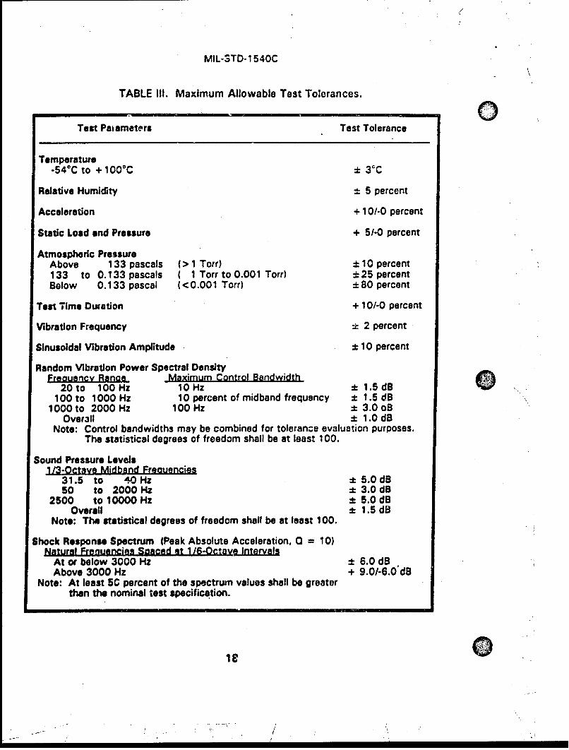
Unless stated otherwise, the specified test parameters should be assumed toInclude the maximum allowable test tolerances listed in Table Ill. For conditionsoutside the ranges specified, the tolerances should be appropriate for the purposeof the test.
4.7 TEST PLANS AND PROCEDURES
The test plans and procedures shall be documented in sufficient detail toprovide the framework for identifying and interrelating all of the individual tests andtest procedures needed.
4.7.1 Test Pla. The test plans should provide a general description of eachtest planned and the conditions of the tests. The test plans should be based upona function-by-function mission en•iymis and any specified testing requirengents. Tothe degree practicable, tests should be planned and executed to fulfill testobjectives from development through operations. Test objectives should beplanned to verify compliance with the design and specified requirements of the
17
/
MIL-STD-1540C
TABLE Ill. Maximum Allowable Test Tolerances.
Test Pakameters Test Tolerance
Temperature
-54 0C to + 1 00°C ± 3rC
Relative Humidity t 5 percent
Acceleration + 10/-0 percent
Static Load and Pressure + 5/-0 percent
Atmospheric PressureAbove 133 pascals (> 1 Torr) :t 10 percent133 to 0.133 pascals ( 1 Torr to 0.001 Torr) :t25 percentBelow 0.133 pascal (<0.001 Torr) :t±80 percent
Test Time Duration + 10/-0 percent
Vibration Frequency 1 2 percent
Sinusoldal Vibration Amplitude :± 10 percent
Random Vibration Power Spectral DensityFreouencv Ranaa Maximum Control Bandwidth
20 to 100Hz 10Hz ± 1.5dB100 to 1000 Hz 10 percent of midband frequency :± 1.5 dB
1000 to 2000 Hz 100 Hz ± 3.0 oBOverall ± 1.0 dB
Note: Control bandwidths may be combined for tolerance evaluation purposes.The statistical degrees of freedom shall be at least 100.
Sound Pressure Levels113-Octave Midband Freouencias
31.5 to 40Hz ± 5.0dB50 to 2000 Hz ± 3.0 dB
2500 tO 10000 Hz ± 5.0 dBOverall ± 1.5 dB
Note: The statistical degrees of freedom shall be at least 100.
Shock Response Spectrum (Peak Absolute Acceleration, 0 = 10)Natural Frenuencies Spaced at 1/6-Octave Intervals
At or below 3000 Hz ± 6.0 dBAbove 3000 Hz + 9.01-6.0'rB
Note: At least 50 percent of the spectrum values shall be greaterthan the nominal test specification.
:eIF
MIL-STD-1 54OC
items involved, including interfaces. The test plans should incorporate byreference, or directly document, the following:
a. A brief background of the applicable project and descriptions of thetest items covered (such as the systems, vehicles, and subtierequipment).
b. The overall test philosophy, testing approach, and test objective foreach item, Including any special tailoring or interpretation of designand testing requirements.
c. The allocation of requiremrents to appropriate testable levels ofassembly. Usually this is a reference to a requirements traceabilitymatrix listing all design requirements and Indicating a cross referenceto a verification method and :o the applicable assembly level.
d. The identification of separate environmental test zones (such as theengine, fairing, or payload).
e. The Identification of separate states or modes where the configurationor environmental levels may be different (such as during testing,launch, upper-stage transfer, on-orbit, eclipse, or reentry).
f. The environmental specifications or life-cycle environmental profi lesfor each of the environmental test zones.
g. Required special test equipment, facilities, interfaces, and downtimerequirements.
h. Required test tools and test beds including the qualification testingplanned for the test tools and test beds to demonstrate that theyrepresent an operational system environment and verify that simulatedinterfaces are correict.
1. Standards to be used for the recording of test data on computercompatible electronic media, such as disks or magnetic tape, tofacilita~te automated accumulation and sorting of data.
j.The review and approval process to be followed for test plans andprocedures, and for making changes to apprcved test plans andprocedures.
19
MIL-STD.1540C
k. Overall schedule of tests showing conformance with theprogram schedules incuding the scheduled availability ot test articles,test facilities, special test equipment, and procedures.
4.7.2 Lest Procedures. Tests - 'all be conducted using doc;umented testprocedures, prepared for performing all of the required tests in accordance with thetest objectives in the approved test plans. The test objectives, testing criteria, andpass-fail criteria shall be stated clearly in the test procedures. The test proceduresshall cover all operations in enough detail so that there is no doubt as to theexecution of any step. Test objectives and criteria should be stated clearly torelate to design or operations specifications. Whr"e appropriate, minmumrequirements for valid data and pass-fail criteria should be provided at theprocedure step level. Traceability should be provided from the spd Aifications orrequirements to the test pro'.edures. Where practicable, the individual procedurestep that satisfies the requirement should be identified The test procedure foreach item shall include, as a minimum, descriptions of the following:
a. Criteria, objectives, assumptions, and constraints.
b. Test setup.
c. Initialization requirements.
d. Input data.
e. Test instrumentation.
f. Expected intermediate test results.
g. Requirements for recording output data.
h. Expected output data.
i. Minimum requirements for valid data to consider the test successful.
j. Pass-fail criteria for evaluating results.
k. Safety considerations and hazardous conditions.
4.8 RETEST
Whenever the design of hardware is changed, the hardware involved should beretested, as necessary, and all documentation pertinent to the changes shall berevised. When retesting a redesigned item, limited testing may be satisfactory aslong as it is adequate to verify the redesign, to confirm that the redesign did notnegate prior testing, and to show that no new problems have been introduced.However, care must be exercised with this limited retesting concept since evensmall changes can potentially affect the item in unexpected ways.
20
• r
MIL-STD-1 540C
Retesting may also be necessary if a test discrepancy (3.5.8) occurs whileperforming any of the required testing steps. In that case, conducting a properfailuie analysis plays an important part in determining the type and degree ofretesting. The failure analysis snould include the determination of whether a failureoccurred, the cause of the failure, the symptoms of the failure, Snd isolation of thefailure to the smallest replaceable item.
4.8.1 Retest Dfuring QuelifiC~tionorAcc2tgc. If a test discrepancy occursduring jualification or bcceptanqe testing, the test may be continued withoutcorrective action if the discrepant item or software coding does not affect thevalidity of test data obtained by the continuation of testing. Otherwise the testshall be Interrupted and the discrepancy verified. To the extent practicable, thetest configuration should not be modified until the cause of the discrepancy hasbeen isolated and verified. If the discrepancy is caused by the test setup, testsoftware, or a failure in the test equipment, the test being conducted at the time ofthe discrepancy may be continued after the cause is removed and repairs arecompleted, as long as the discrepancy did not overstress the item under test. Ifthe discrepancy is caused by a failure of the item under test, the preliminary failureanalysis and appropriate corrective action should normally be completed andproperly documented before testing is resumed. Retesting may be required toestablish a basis for determining compliance of a test item to a specification orrequirement, and may be required to assess the readiness of test items forIntegrated system testing.
4.8.2 Retest Durino Prelaunch Validatign. If a discrepancy occurs duringprelaunch validation testing (integrated system testing), it shall be documented forlater evaluation. The test director is responsible for assessing the effect of thediscrepancy to determine whether the discrepancy has jeopardized the probablesuccess of the remainder of the test. The test director may decide to continue orhalt the test. If continued, the test starts at the test procedure step designated bythe test director. The integrated system testing should be continued, wherepracticable, to conserve time-critical operational resources. When the discrepancyhas been corrected or explained, retesting may be required.
4.8.3 Retest During Ooerational Tests and Evaluations. If a discrepancyoccurs during operational tests and evaluations, it shall be documented for laterevaluetion. The operating agency Is responsible for assessing the effect of thediscrepancy to determine whether the discrepancy has jeopardized the probablesucce3s of the remainder of the test. The operating agency is also responsible fordetermining the degree of retesting required.
21
MIL-STD-1540C
49 DOCUMENTATION
See Subsection 10.5 for additional information.
4.9.1 Test Documentation Files. The test plans and procedures (4.7),including a list of test equipment, calibration dates and accuracy, computersoftware, test data, test log, test results and conclusions, problems or deficiencies,pertinent analyses, and resolutions shall be documented and maintained. The testdocumentation files shall be maintained by the applicable contractors for theduration of their contracts.
4.9.2 Test Dntt. Pertinent test data shall be maintained in a quantitative formto permit the evaluation of performance under the various specified test conditions;pass or fail statements alone may be insufficient. The test data shouid also becompared across major test sequences for trends or evidence of anomalousbehavior. To the extent practicable, all relevant test measurements and tt aenvironmental conditions imposed on the units should be recorded on con.putercompatible electronic media, such as disks, magnetic tape, or by other s,54tablemeans to facilitate automated accumulation and sorting of data for the crtical testparameters. These records are intended to be an accumulation of trend d'lata andcritical test parameters that should be examined for out of tolerance vaiL as and forcharacteristic signatures during transient and mode switching. For deve,.)pmentand qualification tests, a summary of the test results should be documerneed in testreports. The test report should detail the degree of success in meeting the testobjectives of the approved test plans and should document the test results,deficiencies, problems encountered, and problem resolutions.
4.9.3 Igst Lg. Formal test conduct shall be documented in a test log. Thetest log shall identify the personnel involved and be time-tagged to permit areconstruction of test events such as start time, stop time, anomalies, and anyperiods of interruption.
22
I.V
MIL*STD-1 540C
SECTION 5
0 DEVELOPMENT TESTS
5.1 GENiERAL
Development tests, or engineering tests, shall be conducted as required to:
a. Validate new design concepts or the application of proven conceptsand techniques to a new configuration.
b . Assist in the evolution of designs from the conceptual phase to theoperational phase.
c. Reduce the risk involved in committing designs to the fabrication ofqualification and flight hardware.
d. Validate qualification and acceptance test procedures.
e. Investigate problems or concerns that arise after successfulqualification.
Requirements for development testing therefore depend upon the maturity ofthe subsystems and units used and upon the operational requirements of thespecific program. An objectiv'e of development testing is to identify problems earlyin their design evolution so that any required corrective actions can be taken priorto starting formal qualification testing. Development tests should be used toconfirm structural and performance margins, manufacturability, testability,maintainability, reliability, life expectancy, and compatibility with system safety..Where practicable, development tests should be conducted over a range ofoperating conditions that exceeds the design limits to identify marginal capabilitiesand marginal design features. Comprehensive development testing is an especiallyImportant ingredient to mission success in programs that plan to use qualificationItems for flight, including those that allow a reduction In the qualification testlevels and durations. Development tests may be conducted on breadboardequipment, prototype hardware, or the development test vehicle equipment.
Development tests may be conducted at In-plant test facilities, which mayInclude subcontractor's facilities, at a government approved test bed, or at anyother appropriate test facility. However, when performed at a government facility,that facility may require approval of the test plans and procedures. Internalcontractor documentation of development test plans, test procedures, and testresults are normally used unless stated otherwise by contract.
23
MIL-STD-1540C
Tne development test requirements are necessarily unique to each new launchvehicle, upper-stage vehicle, and space vehicle. The following provide guidelinesfor conducting appropriate development tests when their need has beenestablished.
5.2 PART. MATERIAL. AND PROCESS DEVELOPMENT TESTSAND EVALUATIONS
Part, material, and process development tests and evaluations are conductedto demonstrate the feasibility of using certain items or processes in theimplementation of a design. These development tests and evaluations may beconducted to assess design alternatives, manufacturing alternatives, and toevaluate tradeoffs to best achieve the development objectives. Development testsand evaluations are required for new types of parts, materials, and processes; toassure proper application of parts, materials, and processes in the design; and todevelop acceptance criteria for these items to avoid assembling defective units.
Material characterization testing under simulated environmental conditions isnormally conducted for composite laminate, insulations, seals, fluid lines, and itemsnot well characterized for their intended use.
5.3 SUBASSEMBLY DEVELOPMENT TESTS. IN-PROCESS TESTSAND INSPECTIONS
Subassemblies are subjected to development tests and evaluations as requiredto minimize desigr: risk, to demonstrate manufacturing feasibility, and to assess thedesign and manufacturing alternatives and trade-offs required to best achieve thedevelopment objectives. Tests are conducted as required to develop in-processmanufacturing tests, inspections, and acceptanc6 criteria for the items to avoidassembling defective hardware items.
5.4 UNIT DEVELOPMENT TESTS
Units are subjected to development tests and evaluations as may be requiredto minimize design risk, to demonstrate manufacturing feasibility, to establishpackaging designs, to demonstrate electrical and mechanical performance, and todemonstrate the capability to withstand environmental stress including storage,transpow"tion, extreme combined environments, and launch base operations.Temperature cycling and random vibration testing at levels beyond the qualificationrequirements should be conducted to further increase confidence in the design andidentify the weakest elements. New designs should be characterized acrossworst-case voltage, frequency, and temperature variations at the breadboard level.Functional tests of prototype units in thermal and vibration environments arenormally conducted. Development tests of deployables, of thrust vector controls,
24
, .I N

NEMEC=,,--
MIL-STD-1 540C
and of the attitude control subsystem are normally conducted. Life tests of criticalitems that may have a wearout failure mode, such as moving mechanicalassemblies, should also be conducted. Vibration resonance searches of a unitshould be conducted to correlate with a mathematical model and to support designmargin or failure evaluations. Development tests and evaluations of vibration andshock test fixtures should be conducted prior to first use to prevent inadvertentovertesting or uncdartesting, including avoidance of excessive cross-axis responses.These development tests of fixtures should result in the design of shock andvibration test fixtures that can be used during unit qualification and acceptancetests. When it is not practicable to use fixtures of the same design for unitqualification and acceptance tests, evaluation surveys should be performed oneach fixture design to assure that the unit responses are within allowable margins.
5.4.1 Structural Comoosite Develogment Tests. Development tests shall beconducted on structural components made of advanced composites or bondedmaterials, such as payload adapters, payload fairings, motor cases, and composite-overwrapped pressure vessels.
If appropriate, testing should include:
a. *Static load or burst testing to validate the ultimate structuralcapabilities.
b. Damage tolerance testing to define acceptance criteria.
Q c. Acoustic transmission loss test for composite fairings.
5.4.2 Thermal Develodn Test. For critical electrical and electronic unitsdesigned to operate in a vacuum environment less than 0. 133 pascal (0.001 Torr),thermal mapping for known boundary conditions should be performed in thevacuum environment to verify the internal unit thermal analysis, and to providedata for thermal mathematical model correlation. Once correlated, the thermalmodel is used to demonstrate that critical part temperature limits, consistent withreliability requirements and performance, are not exceeded. When electrical andelectronic packaging is not accomplished in accordance with known and acceptedtechniques relative to the interconnect subsystem, parts mounting, board sizes andthickness, number of layers, thermal coefficients of expansion, or installationmethod, development tests should be performed. The tests should establishconfidence In the design and manufacturing processes used. Heat transportcapacity tests may be required for constant and variable conductance heat pipes atthe unit level to demonstrate compliance with 3.3.1. Thermal conductance testsmay be performed to verify conductivity across items such as vibration isolators,thermal isolators, cabling, and any other; potentially significant heat conductionpath.
0;
MIL-STD-1 540C
5.4.3 Shock and Vibrotion Isolator Develooment Tests. When a unit is to bemounted on shock or vibration isolators whose performance is not well known,development testing should be conducted to verify their suitability. The isolatorsshould be exposed to the various induced environments (for example, temperatureand chemical environments) to verify retention of isolator performance (especiallyresonant frequencies and amplifications) and to verify that the isolators haveadequate service life (3.5.6). The unit or a rigid simulator with proper massproperties (mass, center of gravity, mass moments of inertia), should be tested onits isolators in each of three orthogonal axes, and, if necessary, in each of threerotational axes. Responses at all corners of the unit should be determined toevaluate isolator effectiveness and, when applicable, to establish the criteria forunit acceptance testing without isolators (7.4.4). When multiple units aresupported by a vibration isolated panel, responses at all units should be measuredto account for the contribution of panel vibration mndes.
5.5 VEHICLE AND SUBSYSTEM DEVELOPMENT TESTS
Vehicles and subsystems are subjected to development tests and evaluationsusing structural and thermal development models as may be required to confirmdynamic and thermal environmental criteria for design of subsystems, to verifymechanical interfaces, and to assess functional performance of deploymentmechanisms and thermal control subsystems. Vehicle ievel development testingalso provides an opportunity to develop handling and operating procedures as wellas to characterize Interfaces and interactions. 0
5.5.1 Mechanical Fit Development Tests. For launch, upper-stage, and spacevehicles, a mechanical fit, assembly, and operational interface test with thefacilities at the launch or test site is recommended. Flight-weight hardware shouldbe used if practicable; however, a facsimile or portions thereof may be used toconduct the development tests at an early point in the schedule in order to reducethe impact of hardware design changes that may be n9cessary.
5.5.2 Mode Survey DIvelooment Tests. In advance of the qualification modesurvey test (6.2.10), a development mode survey test (or modal survey) should beconducted at the vehicle or subsystem level when uncertainty in analyticallypredicted structural dynamic characteristics is judged to be excessive for purposesof structural or control subsystem design, and an early identification of problemareas is desired. The test article may be full-scale or subscale; for a large vehicle,such as a launch vehicle, a subscale model is often used. Such a development testdoes not replace a modal survey required for vehicle qualification, unless the testalso meets the requirements In 6.2.10.
5.6.3 Structural Develonment Tests. For structures having redundant loadpaths, structural tests may be required to verify the stiffness properties and to
26 0
MIL-STD-1 540C
measure member loads, stress distributions, and deflections. The stiffness dataare of particular interest where nonlinear structural behavior exists that Is not fullyEI~ exercised in a mode survey test (5.5.2, 6.2.10). This may include nonlinearbearings, elastic buckling of panels, gapping at preloaded interfaces, and slipping atfriction joints. The member load and stress distribution data may be used toexperimentally verify the loads transformation matrix. Deflection data may be alsoused to experimentally verify the appropriate deflection transformation matrix.These matrices may be used, in conjunction with the dynamic model, to calculateloads such as axial forces, bending moments, shears, and torsional moments, andvarious stresses and deflections, which can be converted into design load andclearance margins for the vehicle. This development test does not replace thestructural static load test that is required for subsystem qualification (6.3.1);however, the two tests may be Incorporated into a single test sequence thatencompasses the requirements of both tests, provided that the test article isflight-like, the manufacturing log Is up-to-date, and the test plan is preparedaccording to the qualification requirements.
5.5.4 Acoustic and Shock Develogment Tests. Since high-frequency vibrationand shock responses are difficult to predict by analytical techniques, acoustic andshock development testing of the launch, upper-stage, and space vehicles may benecessary to verify the adequacy of the dynamic design criteria for units. Vehicleunits that are not installed at the time of the test should be dynamically simulatedwith respact to mass, center of gravity, moments of Inertia, Interface stiffness, andgeometric characteristics. For the acoustic test, the vehicle is normally exposed tothe qualification acoustic levels in an acoustic chamber. For the shock test, allexplosive-ordnance devices and other mechanisms capable of imparting asignificant shock to the vehicle should be operated. Where practicable, the shocktest should Involve physical separation of elements being deployed or released.When a significant shock Is expected from subsystems not on board the vehicleunder test (such as when a fairing separation Causes shock responses on an upperstage under test), the adaptor subsystem or suitable simulation shall be attachedand appropriate explosive-ordnance devices or other means used to simulate theshock Imposed. The pyroshock environment may vary significantly betweenordnance activations. Therefore, the statistical basis given In 3.3.2 shall be usedfor estimating maximum expected and extreme spectra. Multiple activations ofordnance devices may be used to provide data for better-substantiated estimates.
5.5.5 Thermal Balance Develooment Tests. A thermal balance developmenttest may be necessary to verify the analytical modeling of launch, upper-stage, orspace vehicles, and to verify the unit thermal design criteria. For vehicles in whichthermally Induced structural distortions are critical to mission success, the thermalbalance test also evaluates alignment concerns. The test vehicle should consist ofa thermally equivalent structure with addition of equipment panels, thermal controlInsulation, finishes, and thermally equivalent models of electrical, electronic,
27
MIL-STD-1540C
pneumatic, and mechanical units. Testing should be conducted in a spacesimulation test chamber capable of simulating the ascent, transfer orbit, and orbitalthermal-vacuum conditions as may be appropriate.
5.5.6 Transoortation and Handllng Development Tests. The handling andtransporz of launch, upper-stage, and space vehicles, or their subtier elements, isnormally conducted so as to result in dynamic environmentu well below thoseexpected for launch and flight. However, since these environments are difficult topredict, it is often necessary to conduct a development test tGi potentiallysignificant handling and transportation configurations to determine worst-casedynamic inputs. Such a test should use a development model of the item or asimulator which has at least the proper mass properties, instrumented to measureresponses of the item. In particular, a drop test representative of a maximumcredible operational occurrence should be conducted to demonstrate protection ofthe item in the handling apparatus and shipping container. The data should besufficient to determine whether the environments are benign relative to the designrequirement!, or to provide a basis for an analysis to demonstrate lack of damage,or to augment qualification and acceptance testing, if necessary.
5.5.7 Wind-tunnel Development Tests. Flight vehicle aerodynamic andaerothermal data are needed to establish that the vehicles survive flight, andfunction properly under the imposed loads. For flight vehicles with a new orsignificantly changed aerodynamic design, the following wind-tunnel tests shall beconducted:
a. Force and Moment Tests. These tests provide the resultantaerodynamic forces and moments acting on the vehicle during thehigh-dynamic-pressure region of flight. Data from these tests areused in both structural and control subsystem design and in trajectoryanalysis.
b. Steady-State Pressure Tests. These tests determine the spatialdistribution of the steady-state component of the pressures Imposedon the vehicle's external surfaces during the high-dynamic-pressureregion of flight. These data are used to obtain the axial airloaddistributions which are used to evaluate the static-elasticcharacteristics of the vehicle. These data are also used incompartment venting analyses to determine burst and collapsepressures imposed on the vehicle structure. The design and testing ofthe payload fairing structure are particularly dependent uponhigh-quality definition of th-e pressures.
28
MIL-STD- 1 540C
c. Aerodynamic Heatina Tests. These tests determine the heatingeffects due to fin and fuselage junctures, drag (friction), angle of0 attack, flow transition, shock wave impingement, proximity effects formultibody vehicles, and surface discontinuit• 3s.
d. Base Heatina Tests. These tests determine the heating effects due tothermal radiation, multiplume recirculation convection, plume-inducedflow separation on the vehicle body, and the base flow field.
e. Thruster Plume-Im21noement Heatino Tests. These tests determinethe heating effects due to impingement of the thruster plumes.
f. Transonic and Suoersonle Buffet and Aerodynamic Noise Tests.These tests define the spatial distribution of the unsteady orfluctuating component of the pressures imposed on the vehicleexternal surfaces during the high-dynamic-pressure region of flight..These data are used to obtain the dynamic airloads acting to excitethe various structural modes of the vehicle and are used in aeroelastic,flutter, and vibroacoustic analyses.
g. Ground-wind-induced Oscillation Tests These tests define theresultant forces and moments acting on the vehicle prior to launchwhen it is exposed to the ground-wind environment. Flexible modelsor elastically-mounted rigid models are used to simulate at least thefirst cantilever bending mode of the vehicle. Nearby structures orterrain, which may Influence the flow around the vehicle, shall also besimulated.
29
MIL-STD-1 540C
SECTION 6
QUALIFICATION TESTS0
6.1 GENERAL QUALIFICATION TEST REQUIREMEN2TS
Qualification tests shall be conducted to demonstrate that the design,mn.anufacturing process, and acceptance program produce mission items that meetspecification requirements. In addition, the qualification tests shall validate theplanned acceptance program including test techniques, procedures, equipment,instrumentation, and software. The qualification test baseline shall be tailored foreach program. Each type of flight item that is to be acceptance tested shallundergo a corresponding qualification test, except for certain structural items asidentified herein.
In general, a single qualification test specimen of a given design shall beexposed to all applicable environmental tests. The use of multiple qualification testspecimens may thi required for one-time-use devices (such as explosive ordnanceor solid-propellant rocket motors). Aside from such cases, multiple qualificationspecimens of a given design may be used to enhance confidence in thequalification process, but are not required by this Standard.
6.1.1 Qualification Hardware. The hardware subjected to qualification testingshall be produced from the same drawings, using the same materials, tooling,manufacturing process, and level of personnel competency as used for flighthardware. Ideally, a qualification item would be randomly selected from a group ofproduction items. A vehicle or subsystem qualification test article should befabricated using qualification units to the maximum extent practicable.Modifications are permitted if required to accommodate benign changes that maybe necessary to conduct the test. These changes include adding instrumentationto record functional parameters, test control limits, or design parameters forengineering evaluation. When structural items are rebuilt or reinforced to meetspecific strength or rigidity requirements, all modifications shall be structurallyIdentical to the changes incorporated in. flight articles. The only testing requiredprior to the start of qualification testing of an item is the wear-in (7.4. 10) toachieve a smooth, consistent, and controlled operation of the Item (such as formoving mechanical assemblies, valves, and thrusters).
6.1.2 Qualification Test Levels and Durations. To demz~nstrate margin, thequalification environmental conditions shall stress the qualification hardware tomo. re severe conditions than the maximum conditions that might occur duringservice life (3.5.6), Including not only flight, but also a maximum time or number ofcycles that can be accumulated ;n acceptance testing and retesting. Qualification
30
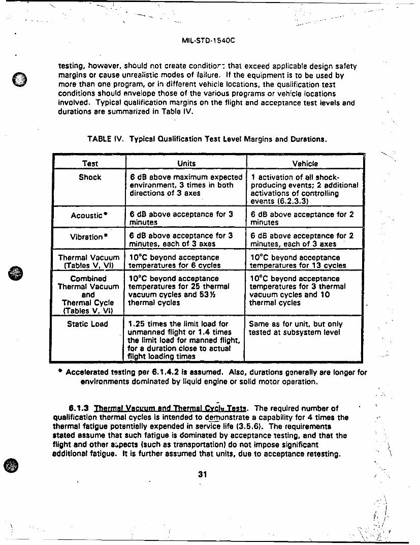
MIL-STD..1 540C
testing, however, should not create conditior: that exceed applicable design safetymrisor cause unrealistic modes of failure. If the equipment is to be used by
more than one program, or in different vehicle locations, the qualification testconditions should envelope those of the various programs or veh~cle locationsinvolved. Typical qualification margins on the flight and acceptance test levels anddurations are summarized In Table IV.
TABLE IV. Typical Qualification Test Level Margins and Durations.
Test Units Vehicle
Shock 6 dB above maximum expected 1 activation Of all shock-environment, 3 times in both producing events; 2 additionaldirections of 3 axes activations of controlling
____________ ____________________events (6.2.3.3)
Acoustic * 6 dB above acceptance for 3 6 dB above acceptance for 2minutes minutes
Vibration * 6 dB above acceptance for 3 6 dB above acceptance for 2_____________minutes, each of 3 axes minutes, each of 3 axes
Thermal Vacuum 100C beyond acceptance 100C beyond acceptance(Tables V, VI) temperatures for 6 cycles temperatures for 13 cycles
Combined 1 00C beyond acceptance 1 00C beyond acceptanceThermal Vacuum temperatures for 25 thermal temperatures for 3 thermal
and vacuum cycles and 53Ya vacuum cycles and 10Thermal Cycle thermal cycles thermal cycles(Tables V, V0) _______________
Static Load 1.25 times the limit load for Same as for unit, but onlyunmanned flight or 1.4 times tested at subsystem levelthe limit load for manned flight,for a duration close to actual
_____________ I flight loading times ______________
Accelerated testing per 6.1.4.2 Is assumed. Also, durations generally are longer forenvironments dominated by liquid engine or solid motor operation.
6.1.3 Thermal VacUUm and Thermal Cvchj Tests. The required number ofqualification thermal cycles is intended to demtinstrate a capability for 4 times thethermal fatigue potentially expended in service life (3.5.6). The requirementsstated assume that such fatigue is dominated by acceptance testing, and that theflight and other azpects (such as transportation) do not impose significantadditional fatigue. It is further assumed that units, due to acceptance retesting.
31
MIL-STD-1 540C
may be subjected to as many as 2 times the number of thermal cycles specified fora basic test. If a different limit on number of cycles is used, the required numberof qualification cycles shall be changed per note 5 oi Table VI. No allowance ismade for acceptance retest of vehicles. For both thermal.cycle and thermalvacuum tests, the temperature ranges in Table V are the basis for the number ofcycles in Table VI for qualification and acceptance testing.
In instances where these baseline requirements are not appropriate due to thetemperature range, acceptance retest allowance, or significance of the mission orother service, the qualification number of cycles shall be modified per note 5 ofTable VI. Also, the maximum allowable number of acceptance thermal cycles canbe extended after the original qualification by performing the required additionaltesting on the qualification test item necessary to meet the requirement in note 5of Table VI.
Electrical and electronic units, or units containing electrical and electronicelements, are subjected to multiple thermal vacuum cycles and thermal cycles forthe purpose of uncovering workmanship deficiencies by a process known asSenvironmental stress screening." Such screening is Intended to identify defectsthat may result in early failures. Therefore the number of cycles imposed isgenerally unrelated to mission thermal cycles. For units not containing electrical orelectronic elemetits, only thermal vacuum testing is required and the number ofthermal cycles are considerably reduced (Table VI, 6.4.3.4, and 7.4.3.3).
6.1.4 Acoustlc and VlbrMtion Qualificagton. For the acoustic and vibrationenvironments, the qualification tests are designed to demonstrate the ability of thetest item to endure both of the following:
a. The acceptance test spectrum (7.1.2 or 7.1.3) for 4 times the maximumallowable duration of acceptance testing of flight items, including anyretesting.
b. The extreme expected spectrum (6 dB higher than acceptance, unless alesser margin can be justified per 3.3.2) for a duration of 4 times thefatigue equivalent duration in flight (3.3.3), but for not less than 1 minute.
The maximum allowable duration of acceptance testing can be extended after theoriginal qualification by performing additional testing on the qualification test item.If one or more electrical or electronic units are involved, this additional acoustic orvibraticn test~ng shall be followed by at least 1.5 thermal cycles or 1.5 thermalvacuum cycles.
Either the approach described In 6.1.4.1 or 6.1.4.2 may be selected forconduct of the qualification testing.
32
- -: ,' ,,
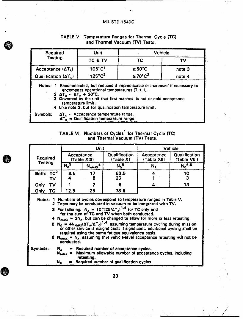
MIL-STD-1 540C
TABLE V. Temperature Ranges for Thermal Cycle (TC)and Tharmal Vacuum (TV) Tests.
Required Unit VehicleTesting TC & TV TC TV
Acceptance (ATA) 1050 C1 > 500C note 3
Qualification (AT 0 ) 1250C 2 > 70°C2 note 4
Notes: 1 Recommended, but reduced if impracticable or increased if necessary toencompass operational temperatures (7.1.1).
2 &TO - ATA + 20 0C.3 Governed by the unit that first reaches its hot or cold acceptance
temperature limit.4 Like note 3, but for qualification temperature limit.
Symbols: ATA - Acceptance temperature range.ATO = Qualification temperature range.
TABLE VI. Numbers of Cyclesi for Thermal Cycle (TC)and Thermal Vacuum (TV) Tests.
Unit VehicleAcceptance Qualification Acceptance Qualification
Required (Table XI1I) (Table X) (Table XIl) (Table VIII)Testing N x4 N0
5 NO N05 ,6
Both: TC2 8.5 17 53.5 4 10TV 4 8 25 1 3
Only TV 1 2 6 4 13Only TC 12.5 25 78.5
Notes: 1 Numbers of cycles correspond to temperature ranges in Table V.2 Tests may be conducted in vacuum to be integrated with TV.3 For tailoring: NA - 10(125/&TA) 1'4 for TC only and
for the sum of TC and TV when both conducted.4 NAwx - 2 NA, but can be changed to allow for more or less retesting.5 No - 4NAvAx(&TA/ATQ)", assuming temperature cycling during mission
or other service is insignificant; if significant, additional cycling shall berequired using the same fatigue equivalence basis.
6 Nvx - NA, assuming that vehicle-level acceptance retesting w1ll not beconducted.
Symbols: NA - Required number of acceptance cycles.NAw~x - Maximum allowable number of acceptance cycles, including
retesting.No - Required number of qualification cycles.
33
-- -- - /- -
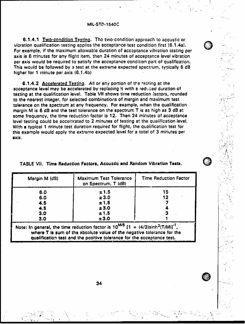
MIL-STD-1540C
6.1.4.1 Two-condition T stina. The two-condition approach to acoustic orvibration qualification testing applies the acceptance test condition first (6.1.4a). "For example, if the maximum allowable duration of accaptance vibration testing peraxis is 6 minutes for any flight item, then 24 minutes of acceptance level vibrationper axis would be required to satisfy the acceptance condition part of qualification.This would be followed by 3 test at the extreme expected spectrum, typically 6 dBhigher for 1 minute per axis (6.1.4b)
6.1.4.2 Accelerated Testing. All or any portion of the ,'asting at theacceptance level may be accelerated by replacing it with a redujed duration oftasting at the qualification level. Table VII shows time reduction ;'actors, roundedto the nearest integer, for selected combinations of margin and maximum testtolerance on the spectrum at any frequency. For example, when the qualificationmargin M is 6 dB and the test tolerance on the spectrum T is as high as 3 dB atsome frequency, the time reduction factor is 12. Then 24 minutes of acceptancelevel testing could be accelerated to 2 minutes of testing at the qualification level.With a typical 1 minute test duration required for flight, the qualification test forthis example would apply the extreme expected level for a total of 3 minutes peraxis.
TABLE VII. Time Reduction Factors, Acoustic and Random Vibration Teats. 0Margin M (dB) Maximum Test Tolerance Time Reduction Factor
on Spectrum, T (dB)
6.0 ± 1.5 156.0 ± 3.0 124.5 ±1.5 74.5 ±3.0 43.0 ± 1.5 33.0 ±3.0 1
Note: In general, the time reduction factor is 10 [1 + (4/3)sinh2(T/M)]",where T is sum of the absolute value of the negative tolerance for thequalification test and the positive tolerance for the acceptance test.
34
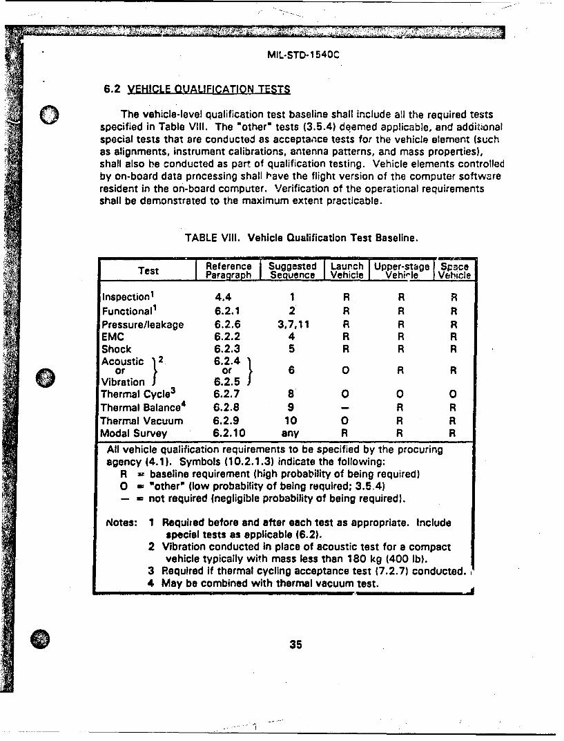
MIL-STD-1 540C
6.2 VEHICLE QUALIFICATION TESTS
JThe vehicle-level qualification test baseline shall include all the required testsspecified in Table VIII. The "other" tests (3.5.4) deemed applicable, and additionalspecial tests that are conducted as acceptance tests for the vehicle element (suchas alignments, instrument calibrations, antenna patterns, and mass properties),shall also be conducted as part of qualification testing. Vehicle elements controlledby on-board data prncessing shall have the flight version of the computer softwareresident in the on-board computer. Verification of the operational requirementsshall be demonstrated to the maximum extent practicable.
TABLE VIII. Vehicle Qualification Test Baseline.
Reference Suggested Launch Upper-stage SpaceTest Paragraph Sequence Vehicle Vehi,'e Vehicle
Inspection1 4.4 1 R R RFunctional1 6.2.1 2 R R RPressure/leakage 6.2.6 3,7,11 R R REMC 6.2.2 4 R R RShock 6.2.3 5 R R R
coustic 12 6.2.4 1or or 6 0 R R
Vibration 6.2.5Thermal Cycle3 6.2.7 8 0 0 0Thermal Balance 4 6.2.8 9 - R RThermal Vacuum 6.2.9 10 0 R RModal Survey 6.2.10 any R R R
All vehicle qualification requirements to be specified by the procuringagency (4.1). Symbols (10.2.1.3) indicate the following:
R - baseline requirement (high probability of being required)0 W Notherp (low probability of being required; 3.5.4)- - not required (negligible probability of being required).
Notes: 1 Requited before and after each test as appropriate. Includespecial tests as applicable (6.2).
2 Vibration conducted In place of acoustic test for a compactvehicle typically with mass less than 180 kg (400 Ib).
3 Required if thermal cycling acceptance test (7.2.7) conducted.4 May be combined with thermal vacuum test.
35
MIL-STD-1 540C
6.2.1 Functional Test. Vehicle Qualification
6.2.1.1 PIuJg.s.. The functional test verifies that the mechanical andelectrical performance of the vehicle meet the specification requirements, includingcompatibility with ground support equipment, and validates all test techniques andsoftware algorithms used in computer-assivted commanding and data processing.Proper operation of all redundant units or mechanisms should be demonstrated tothe maximum extent practicable.
6.2.1.2 Mechanical Functional Test. Mechanical devices, valves, deployables,and separation subsystems shall be functionally tested at the vehicle level in thelaunch, orbital, or recovery configuration appropriate to the function. Alignmentchecks shall be made where appropriate. Fit checks shall be made of the vehiclephysical interfaces using master gages or interface assemblies. The test shouldvalidate that the vehicle performs within maximum and minimum limits underworst-case conditions including environments, time, and other applicablerequirements. Tests shall demonstrate positive margins of strength, torque, andrelated kinematics and clearances. Where operation in earth gravity or in anoperational temperature environment cannot be performed, a suitable ground testfixture may be used to permit operation and performance evaluation. The pass-failcriteria shall be adjusted as appropriate to account for worst-case maximum andminimum limits that have been modified to adjust for ground test conditions.
6.2.1.3 Electrical and Fiber-optic Circuit Functional Test. The vehicle shouldbe in its flight configuration with all units and subsystems connected, exceptexplosive-ordnance elements. The test shall verify the integrity of electrical andfiber-optic circuits, including functions, redundancies, end-to-end paths, and atlea-'t nominal performance, including radio-frequency and other sensor inputs.End-to-end sensor testing may be accomplished with a self-test or coupled inputs.
The test shall be designed to operate all units, primary and redundant, and toexercise all commands and operational modes to the extont practicable. Theogloration of all thermally controlled units, such as heaters and thermostats, shallbe verified by test. Where control of such units is implemented by sensors,electrical or electronic devices, coded algorithms, or a computer, end-to-endperformance testing should be conducted. The test shall demonstrate that allcorim.ands having precondition requirements (such as enable, disable, a specificequipment configuration, and a specific command sequence), cannot be executedunless the preconditions are satisfied. Whenever practicable, equipmentperforman-.e parameters that might affect end-ta-end performance (such as power,voltag., gain, frequerncy, command and data rates) shall be varied overspecification ranges to demonstrate the performance. Autonomous functions shallbe verified to occur when the conditions exist for which they are designed.Continuous monitoring of several perceptive parameters, including input and output
36
.: h.. • ,!..
7' t>'-.
MIL-STD-1 540C
parameters, and the vehicle main bus by a power transient monitoring device, shallbe provided to detect intermittent failures.
For at least one functional test in the qualification sequence, the vehicle shallbe operated through a mission profile with all events occurring in actual flightsequence to the extent practicable. This sequence shall include the finalcountdown, launch, ascent, separation, upper-stage operation, orbital operation,and return from orbit as appropriate. All explosive-ordnance firing circuits shall beenergized and monitored during these events to verify that the proper energydensity is delivered to each device and in the proper sequence. All measurementsthat are telemetered shall also be monitored during appropriate portions of theseevents to verify proper operations.
6.2.1.4 Suoolementarv Reauirements. Functional tests shall be conductedbefore and after each of the vehicle tests to detect equipment anomalies and toassure that performance meets specification requirements. These tests do notrequire the mission profile sequence. Sufficient data shall be analyzed to verify theadequacy of the testing and the validity of the data before any change is made toan environmental test configuration, so that any required retesting can be readilyaccomplished. During these tests, the maximum use of telemetry shall beemployed for data acquisition, problem identification, and problem isolation.Functional tests required during individual vehicle tests are specified in connectionwith each test.
0 6.2.2 Electromagnetic Comoatibilitv Test. Vehicle Qualification
6.2.2.1 Purose. The electromagnetic compatibility test demonstrateselectromagnetic compatibility of the vehicle and ensures that adequate marginsexist in a simulated launch, orbital, disposal, and return-from-orbit electromagneticenvironment.
6.2.2.2 ITst Descriotion. The operation of the vehicle and selection ofinstrumentation shall be suitable for determining the margin against malfunctionsand unacceptable or undeired responses due to electromagnetic incompatibilities.The test shall demonstrate satisfactory electrical and electronic equipmentoperation in conjunction with the expected electromagnetic radiation from othersubsystems or equipment, such as from other vehicle elements and ground supportequipment. The vehicle shall be subject=,i to the required tests while In thelaunch, orbital, and return-from-orbit configurations and in all possible operationalmodes, as applicable. Special attention shall be given to areas indicated to bemarginal by analysis. Potential electromagnetic interference from the test vehicleto other subsystems shall be measured. The tests shall be conducted according tothe requirements of MIL-STD-, ,1. The tests shall include but not be limited tothree main segments:
37
MIL-STD-1 540C
a. Radiated emissions susceptibility.
b. Intersystem radiated susceptibility.Q
c. External radii, frequency interference suscepto'bility.
Explosive-ordnance devices having bridge wires, but otherwise inert, shall beinstalled in the vehicle and monitored during all tests.
6.2.3 Shock Test. Vehicle Qualification
6.2.3.1 PurwQas . The shock test demonstrates the capability of the vehicle towithstand or, if appropriate, to operate in the induced shock environments. Theshock test also yields the data to validate the extreme and maximum expected unitshock requirement (3.3.7).
6.2.3.2 TestLA 12sristi1n. The vehicle shall be supported and configured toallow flight-like dynamic response of the vehicle with respect to amplitude,frequency content, and paths of transmission. Support of the vehicle may varyduring the course of a souries of shock tests in order to reflect the configuration 81.the time of each shock event. Test setups shall avoid undue influence of testfixtures, and prevent recontact of separated portions.
In the shock test or series of shock tests, the vehicle shall be subjected toshock transients that simulate the extreme expected shock environment (3.3.7) tothe extent practicable. Shock events to be considered include separations anddeployments initiated by explosive ordnance or other devices, as well as impactsand suddenly applied or released loads that may be significant for unit dynamicresponse (such as due to an engine transient, parachute deployment, and vehiclelanding). All devices on the vehicle capable of imparting significant shockexcitation to vehicle units shall be activated. Those potentially significant shocksources not on the vehicle under test, such as on an adjoining payload fairing or anearby staging joint, shall also be actuated or simulated and applied throughappropriate interfacing structures. Dynamic Instrumentation shall be installed tomeasure shock responses in 3 orthogonal directions at attachments of selectedunits.
6.2.3.3 Test Acla~tigoai. All explosive-ordnance devices and other potentallysignificant shock-producing devices or events, including those from sources notinstalled on the vehicle under test, shall be activated at least one time or simulatedas appropriate. Significant shock sources are those that induce a shock responsespectrum (3.3.7) at any unit location that is within 6 dB of the envelope of theshock response spectra from all shock sources. The significant sources shall beactivated 2 additional times to provide for variability in the vehicle test and toprovide data for prediction of maximum and extreme expected shock environments
38
MIL-STD-1540C
for units (3.3.2). Activation of both primary and redundant devices shall be carriedo1 out in the same sequence as they are intended to operate in service.
6.2.3.4 Supplementary Reouiremerts. Electrical and electronic units shall beoperating and monitored to the maximum extent practicable. Continuousmonitoring of several perceptive parameters, including input and outputparameters, and the vehicle main bus by a power transient monitoring device, shallbe provided to detect intermittent failures.
6.2.4 Acouslic Test. Vehicle Qualification
6.2.4.1 EPulw2o. The acoustic test demonstrates the ability of the vehicle toendure acoustic acceptance testing and meet requirements during and afterexposure to the extreme expected acoustic environment in flight (3.3.4). Exceptfor items whose environment is dominated by structure-borne vibration, theacoustic ter' also verifies the adequacy of unit vibration qualification levels andserves as a 4ualification test for items not tested at a lower level of assembly.
6.2.4.2 Test Descriotion. The vehicle in its ascent configuration shall beInstalled in an acoustic test facility capable of generating sound fields or fluctuatingsurface pressures that induce vehicle vibration env;ronments sufficient for vehiclequalification. The vehicle shall be mounted on a flight-type support structure orreasonable simulation thereof. Significant fluid and pressure conditions shall bereplicated to the extent practicable. Appropriate dynamic instrumentation soall beinstalled to measure vibration responses at attachment points of critical andrepresentative units. Control microphones shall be placed at a minimum of 4well-separated locations, preferably at one half the distance from the test article tothe nearest chamber wall, but no closer than 0.5 meter (20 inches) to both the testarticle surface and the chamber wall. When test article size exceeds facilitycapability, the vehicle may be appropriately subdivided and acoustically tested asono or more subsystems or assemblies.
6.2.4.3 Test Level and Duration. The test shall be conducted per 6.1.4. Thetypical version of the test involves accelerated acceptance-level testing per 6.1.4.2and applies the qualification-level spectrum for a total of 2 minutes. This is basedon a qualification margin of 6 dB, a maximum of 3 minutes of accumulatedacceptance testing on a flight vehicle, and a fatigue equivalent duration of notgreater than 15 seconds. Operating time should be divided approximately equallybetween redundant functions. Where insufficient test time is available to testredundant units, functions, and modes that are operating during the launch,ascent, or reentry phase, extended testing shall be performed at a level no lowerthan 6 dB below the qualification level.
39

MIL,-STri- 15407ýý
6.2.4.4 Suoplemente2r Rloulrements. During the test, all electrical andelectronic units, even if not operating during launch, shall be electrically energizedand sequenced through operational modes to the maximum extent practicable,with the exception of units that may sustain damage If energized. Continuousmonitoring of several perceptive parameters, including input and outputparameters, and the vehicle main bus by a power transient monitoring device, shallbe provided to detect intermittent failures.
6.2.5 Vibralon Test. Vehicle Quallfication. The vibration test may beconducted instead of an acoustic test (6.2.4) for small, compact vehicles whichcan be excited more effectively via interface vibration than by an acoustic field.Such vehicles typically have a mass under 180 kilograms (400 pounds).
6.2.5.1 Eurnglos. The vibration test demonstrates the ability of the vehicle toendure vibration acceptance testing and meet requirements during and afterexposure to the extreme expected environment in flight (3.3.5). Except for itemswhose response is dominated by acoustic excitation, the vibration test also verifiesthe adequacy of unit vibration qualification levels and serves as a qualification testfor items that have not been tested at a lower level of assembly.
6.2.5.2 Test DescriptIon. The vehicle and a flight-type adapter, in the ascentconfiguration, shall be vibrated using one or more shakers through appropriatevibration fixtures. Vibration shall be applied in each of 3 orthogonal axes, onedirection being parallel to the vehicle thrust axis. Instrumentation shall be installedto measure, in those same 3 axes, the vibration inputs and the vibration responsesat attachment points of critical and representative units. Q
6.2.5.3 Tes Levels and Duration. The test shall be conducted per 6.1.4 toproduce the required spectrum at the input to the vehicle or at attachment pointsof critical or representative units, as spaecified. When necessar; to preventunrealistic input forces or unit responses, the spectrum at the vehicle input may belimited or notched, but not below the minimum spectrum for a vehicle (7.1.3). Thetypical version of the test for each axis involves accelerated acceptance-leveltesting per 6.1.4.2 and applies the qualification spectrum for 2 minutes (samebasis as in 6.2.4.3). Operating time should be divided approximately equallybetween redundant functions. Where insufficient test time is available to testredundant units, functions, and modes that are operating during the launch,ascent, or reentry phase, extended testing shall be performed at a level no lowerthan 6 dB below the qualification level.
6.2.5.4 Suoolementarv Regulrements. Same as 6.2.4.4, except that thestructural response shall also be monitored to ensure that no unrealistic testconditions occur.
40
MIL-STD-1 540C
6.2.6 Pressure and Leakmaoe Tests. Vehicle Qualification
6.2.6.1 Purgos.. These tests demonstrate the capability of pressurizedsubsystems tc meet the specified flow, pressure, and leakage rate requirements.
6.2.6.2 Test Descrigtion. The vehicle shall be placed in a facility thatprovides the services and safety conditions required to protect personnel andequipment during the testing of high-pressure subsystems and in the handling ofdangerous fluids. Preliminary tests shall be performed, as necessary, to verifycompatibility with the test setup and to ensure proper control of the equipment andtest functions. The requirements of the subsystem including flow, leakage, andregulation shall be measured while operating applicable valves, pumps, and motors.The flow checks shall verify that tho plumbing configurations are adequate.Checks for subsystem cleanliness, moisture levels, and pH levels shall also bemade. Where pressurized subsystems are assembled with other than brazed orwelded connections, the specified torque values for these connections shall beverified prior to the initial qualification leak check.
In addition to the high-pressure test, propellant tanks and thruster valves shallbe tested for leakage under propellant servicing conditions. The subsystem shallbe evacuated to the internal pressure normally used for propellant loading and thepressure monitored for decay as an indication of leakage.
6.2.6.3 Test Levels and Durations.
a. For launch and upper-stage vehicles which contain pressurizedstructures, the pressurized subsystem shall be pressurized to a proofpressure which is 1.1 times the maximum expected operatingpressure (MEOP) and held constant for a short dwell time, sufficientto assure that the proper pressure was achieved within the allowedtest tolerance. The test pressure shall then be reduced to the MEOPfor leakage inspection.
b. For space vehicles, unless specified otherwise, the pressurizedsubsystems shall be pressurized to a proof pressure which is 1.25times the MEOP and held for 5 minutes and then the pressure shall bereduced to the MEOP. This sequence shall be conducted 3 times,followed by inspection for leakage at the MEOP. The duration of theevacuated propulsion subsystem leakage test shall not exceed thetime that this condition is normally experienced during propellantloading.
6.2.6.4 SuRooementarv Regulrements. Applicable safety standards shall befollowed in conducting all tests. Tests for detecting external leakage shall be
41
MIL-STD-1540C
performed at such locations as joints, fittings, plugs, and lines. The acceptableleakage rate to meet mission requirements shall be based upon an appropriateanalysis. In addition, the measurement technique shall account for leakage ratevariations with pressure and temperature and have the required threshold,resolution, and accuracy to detect any leakage equal to or greater than theacceptable leak rate. If appropriate, the leakage rate measurement shall beperformed at the MEOP and at operational temperature, with the representativefluid commodity, to account for dimensional and viscosity changes. Times toachieve thermal and pressure equilibrium, test duration, and temperature sensitivityshall be determined by an appropriate combination of analysis and developmenttest, and the results documented. Leakage detection arid measurement proceduresmay require vacuum chambers, bagging of the entire vehicle or localized areas, orother special techniques to achieve the required accuracies.
6.2.7 Thermal Cycle Test. Vehicle Qualification
6.2.7.1 PurtP.Q.l. The thermal cycle test demonstrates the ability of thevehicle to withstand the stressing associated with flight vehicle thermal cycleacceptance testing, with a qualification margin on temperature range and maximumnumber of cycles. The thermal cycle test, in combination with a reduced-cyclethermal vacuum test, can be selected as an alternate to the thermal vacuum test(6.2.b and Table VI).
6.2.7.2 Test Descriotlon. The vehicle shall be placed in a thermal chamber at 0ambient pressure, and a functional test shall be performed to assure readiness forthe test. The vehicle shall be operated and monitored during the entire test,except that vehicle power may be turned off if necessary to reach stabilization atthe cold temperature. Vehicle operation shall be asynchronous with thetemperature cycling, and redundant units shall be operated for approximately equaltimes.
When the relative humidity of the inside spaces of the vehicle is below thevalue at which the cold test temperature would cause condensation, thetemperature cycling shall begin. One complete thermal cycle is a period beginningat ambient temperature, then cycling to one temperature extreme and stabilizing(3.5.7), then to the other temperature extreme and stabilizing, and then returningto ambient temperature. Strategically placed temperature monitors installed onunits shall assure attainment and stabilization of the expected temperatureextremes for several units. Auxiliary heating and cooling may be employed forselected temperature-sensitive units (e.g., batteries). If it is necessary in order toachieve the required temoerature rate of change, parts of the vehicle such as solararrays and passive thermal equipmernt may be removed for the test. The lastthermal cycle shall contain cold and hot soaks during which the vehicle shallundergo a functional test, including testing of redundant units.
420
MIL.STD-1540C
6.2.7.3 Test Level and Duration. The minimum vehicle temperature rangeshall be 700C from the hot to the cold condition (Table V). With the 700Cqualification temperature range, the required number of cycles shall be 10. Forother ranges, see Table VI. The average rate of change of temperature shall be asrapid as practicable.
6.2.7.4 Sugolementarv Reauirements. Continuous monitoring of severalperceptive parameters, including input and output parameters and the vehicle mainbus by a power transient monitoring device, shall be provided to detect intermittentfailures. Moisture condensation inside of electrical and electronic units shall beprevented. Combinations of temperature and humidity which allow moisturedeposition either on the exterior surfaces of the vehicle or inside spaces where thehumidity is slow to diffuse (for example, multilayer insulation) shall be avoided.
6.2.8 Thermal Balance Test. Vehicle Qualificstion
6.2.8.1 Purwose. The thermal balance test provides the data necessary toverify the analytical thermal model and demonstrates the ability of the vehiclethermal control subsystem to maintain the specified operational temperature limitsof the units and throughout the entire vehicle. The thermal balance test alsoverifies the adequacy of unit thermal design criteria. The thermal balance tlp. •:• "be combined with the thermal vacuum test (6.2.9).
6.2.8.2 Test Descriltlon. The qualification vehicle shall be tested to simulatethe thermal environment experienced by the vehicle during its mission. Tests shallbe capable of validating the thermal model over the full mission range of seasons,equipment duty cycles, ascent conditions, solar angles, maximum and minimumunit thermal dissipations including effects of bus voltage variations, and eclipsecombinations so as to include the worst-case hot and cold temperatures for allvehicle units. As a minimum, two test conditions shall be imposed: a worst hotcase and a worst cold case. If practicable, 2 additional cases should be imposed:a transient for correlation with the model and a case chosen to check the validityof the correlated model. Special emphasis shall be placed on defining the testconditions expected to produce the maximum and minimum temperatures ofsensitive units such as batteries. Sufficient measurements shall be made on thevehicle internal and external units to verify the vehicle thermal design andanalyses. The power requirements of all thermostatically or electronicallycontrolled heaters and coolers shall be verified during the test, and appropriatecontrol authority demonstrated.
The test chamber, with the test item installed, shall provide a pressure of nohigher than 13.3 millipascal (104 Torr) for space and upper-stage vehicles, or apressure commensurate with service altitude for launch vehicles. Whereappropriate, provisions should be made to prevent the test item from 'viewing"
43
MIL-STD-1 540C
warm chamber walls, by using black-coated cryogenic shrouds of sufficient areaand shape that are capable of approximating liquid nitrogen temperatures. The 0vehicle thermal environment may be supplied by one of the following methods:
a. Abso.rbedFJLu. The absorbed solar, albedo, and planetary irradiationis simulated using heater panels or infrared (IR) lamps with theirspectrum adjusted for the external thermal coating properties, or usingelectrical resistance heaters attached to vehicle surfaces.
b. IngIdnt Flux. The intensity, spectral content, and angular distributionof the Incident solar, albedo, and planetary Irradiation are simulated.
c. Equivalent Radiation Sink Temaerature. The equivalent radiation sinktemperawure is simulated using infrared lamps and calorimeters withoptical properties identical to those of the vehicle surface.
d. C. The thermal environment is supplied by a combinationof tha above methods.
The selection of the method and fidelity of the simutlation depends upon detailsof the vehicle thermal design such as vehicle geometry, the size of internallyproduced heat loads compared with those supplied by the external environment,and the thermal characteristics of the external surfaces. Instrumentation shall beincorporated down to the unit level to evaluate total vehicle performance withinoperational limits as well as to identify unit problems. The vehicle shall beoperated and monitored throughout the test. Dynamic flight simulation of thevehicle thermal environment should be provided unless the external vehicletemperature does not vary significantly with time. (See 10.3 regarding formationof a Test Evaluation Team.)
6.2.8.3 Test Levels and Duratlonp. Test conditions and durations for thethermal balance test are dependent upon the vehicle configuration, design, andmission details. Normally, boundary conditions foe evaluating thermal design shallinclude both of the following:
a. Maximum external absorbed flux plus maximum internal powerdissipation.
b. Minimum external absorbed flux plus minimum internal powerdissip3tion.
The thermal time constant of the subsystems and mission profile both influencethe time required for the vehicle to achieve thermal equilibrium and hence the testduration. 0
44
MIL-STD-1 540C
6.2.8.4 Sulolementnrv Reaulrements. Success criteria depend not only onsurvival and operation of each item within specified temperature limits, but also oncorrelation of the test data with theoretical thermal models. As a goal, correlationof test results to the thermal model predictions should be within ± 3VC. Lack ofcorrelation with the theoretical models may indicate either a deficiency in themodel, test setup, or vehicle hardware. The correlated thermal math model shallbe used to make the final temperature predictions for the various mission phases(such as prelaunch, ascent, on-orbit, and disposal orbit).
6.2.9 Thermal Vacuum Test. Vehicle QOaliflcatlun.
6.2.9.1 Purpose. The thermal vacuum test demonstrates the ability of thevehicle to meet qualification requirements under vacuum conditions andtemperature extremes which simulate those predi'rted for flight plus a dcsignmargin, and to withstand the thermal stressing environment of the vehicle thermalvacuum acceptance test plus a qualification margin on temperature range andnumber of cycles.-
6.2.9.2 Test Description. The vehicle shall be placed in a thermal vacuumchamber and a functional test performed to assure readiness for chamber closure.The vehic!e shall be divided into separate equipmernt zones, based on the limits ofthe temperature-sensitive units and similar unit qualification temperatures withineach zone. Units that operate during ascent shall be operating and monitored forcorona and multipacting, as applicable, as the pressure is reduced to the lowestspecified level. The rate of chamber pressure reduction shall be no greater thanduring ascent, and may have to be slower to allow sufficient time to monitor forcorona and multipacting. Equipment that does not operate during launch shallhave electrical power applied after the lowest specified pressure level has beenreached. A thermal cycle begins with the vehicle at ambient temperature. Thetemperature is raised to the specified high level and stabilized (3.5.7). Followingthe high-temperature soak, the temperature shall be reduced to the lowestspecified level and stabilized. Following the low-temperature soak, the vehicleshall be returned to ambient temperature to complete one thermal cycle.Functdonal tests shall be conducted during the first and last thermal cycle at boththe high- and low-temperature limits with functional operation and .monitoring ofperceptive parameters during all other cycles. If simulation of the ascentenvironment Is desirable at the beginning of the test, the first cycle may begin witha transition to cold thermal environment, rather than a hot thermal environment.
In addition to the thermal cycles for an upper-stage or space vehicle, thechamber may be programmed to simulate various orbital flight operations.Execution of operational sequences shall be coordinated with expectedenvironmental conditions, and a complete cycling of all equipment shall be
45
MIL-STD-1 540C
performed including the operating and monitoring of redundant units and paths.Vehicle electrical equipment shall be operating and monitored throughout the test.Temperature monitors shall assure attainment of temperature limits. Strategicallyplaced witness plates, quartz crystal microbalances. or other instrumentation shallbe installed in the test chamber to measure the outgassing from the vehicle andtest equipment.
6.2.9.3 Test Levels and Duration. Temperatures in various equipment areasshall be controlled by the external test environment and interna; heating resultingfrom equipment operation. During the hot and cold half cycles, the temperaturelimit is reachad as soon as one unit in each equipment area is at the hot or coldtemperature reached during its qualification thermal testing. Unit temperaturesshall not be allowed to go outside their qualification range at any time during thetest. The pressure shall be maintained at no higher than 13.3 millipascal (104Torr) for space and upper-stage vehicles and, for launch vehicles, at no higher thanthe pressure commensurate with the highest possible service altitude. When thealternate thermal cycle test (6.2.7) is not performed, the thermal vacuumqualification test shall include at least 13 complete hot-cold cycles (Table VI).When thermal cycling is performed, the thermal vacuum qualification test shallinclude at least 3 complete hot-cold cycles (Table VI).
The rate of temperature change shall equal or exceed the maximum predictedmission rate of change. The temperature soak (3.5.10) shall be at least 8 hours ateach temperature extreme during the first and last cycles. For intermediate cycles,the soak duration shall be at least 4 hours. Operating time should be dividedapproximately equally between redundant units.
6.2.9.4 SuRnlementarv Reouirements. Continuous monitoring of severalperceptive parameters, including input and output parameters, and the vehicle mainbus by a power transient monitoring device, shall be provided to detect intermittentfailures. It may be necessary to achieve temperature limits at certain locations byaltering thermal boundary conditions locally or by altering the operational sequenceto provide additional heating or cooling. Adjacent equipments may be turned on oroff; however, any soecial conditioning within the vehicle shall generally be avoided.External baffling, shadowing, or heating shall be utilized to the extent feasible.The vehicle shall be operated over the qualification temperature range, althoughperformance within specification Is not required outside of 1 00 C beyond themaximum and minimum expected temperatures.
6.2.10 Mode Survey Test. Vehicle Qulification.
6.2.10.1 Euwse. The mode survey test (or modal survey) is conducted toexperimentally derive a structural dynamic model of a vehicle or to provide a basisfor test-verification of an analytical model. After upgrading analytically to the flight o
46
MIL-STD-1 540C
configuration (such as different propellant loading and minor differences betweenflight and test unit mass properties), this model is used in analytical simulations offlight loading events to define the verification-cycle structural loads environment.These loads are used to determine structural margins and adequacy of thestructural static test loading conditions (6.3.1). Thby are therefore critical forverification of vehicle structural integrity and qualification of the structuralsubsystem as flight-ready. Where practicable, a modal survey is also performed todefine or verify models used in the final preflight evaluation of structural dynamiceffects on control subsystem precision and stability.
6.2.10.2 Test Descriotion. The test article shall consist of flight-qualitystructure with assembled units, payloads, and other major subsystems, and shallcontain actual or simulated liquids at specified fill-levels. For large vehicles,complexity and testing practicability may dictate that tests be performed onseparate sections of the vehicle. For large launch vehicles in particular, practicalitymay also dictate use of an integrated program of ground and flight tests, involvingsubstantibl flight da~ta acquisition and analysis, to acquire the necessary data formodel verification. Wire harnesses may be installed for the mode survey tea3t, butare not required. Mass simulators may be used to represent a flight Item when itsattachment-fixed resonances have been demonstrated by test to occur above thefrequency range of interest established for the modal survey. Dynamic simulatorsmay be used for Items that have resonances within the frequency range of interestIf they are accurate dynamic representations of the flight item. Alternatively, masssimulators may be used if flight-quality items are subjected sesoarately to a modalsurvey meeting qualification requirements. All mass simulators are to Includerealistic simulation of interface attach structure and artificial stiffening of the teststructure shall be avoided.
The data obtained in the modal survey shall be adequate to define the resonantfrequencies and associated mode shapes and damping values, for all modes thatoccur in the frequency range of interest, generally up to at least 50 Hz. Inaddition, the primary mode shall be acquired In each coordinate direction, even ifIts frequency lies outside the specified test range. The test modes are consideredto have acceptable quality when they are orthogonal, with respect to the analyticalmass matrix, to within 10 percent. (See 10.3 regarding formation of a TestEvaluation Team to facilitate deviations from these requirements.)
8.2.10.3 TestLayfill. The test is gonerally conducted at response levels thatare low compared to the expected flight levels. Limited testing shinil be conductedto evaluate nonlinear behavior, with a minimum of 3 levels used when significantnonlinearity 1s Identified.
47
i -
MIL-STD-1 540C
6.2.10.4 Sunolementary Reguirements.
6.2.10.4.1 Correlat on Recuirements. When the modal survey data are used 0to test-verlify an analytical dynamic model for the verificatior -cycle loads analyses,rather than to define the model directly, adequate model-to-: :st correlation shall bedemonstrated quantitatively as follows:
a. Using a cross-orthogonality matrix formed from the analytical massmatrix and the analytical and test modes, corresponding modes are toexhibit at least 95-percent correlation and dissimilar modes are to beorthogonal to within 10 percent.
b. Analytical model frequencies are to be within 3 percent of testfrequencies.
With adequate justification, limited exceptions to this standard of correlation areacceptable for problem modes; a!so, alternative quantitative techniques can beused if their criteria for acceptability are comparable.
6.2.10.4.2 Pretest Reguirements. Because of their criticality to achieving asuccessful test, appropriate oretest analyses and experimentation shall beperformed to:
a. Establish adequacy of the test instrumentation. Qb. Evaluate the test stand and fixturing to preclude any boundary
condition uncertainties that could compromise test objectives.
c. Verify that mass simulators have no rescrances within the frequencyrange of interest.
6.3 SUBSYSTEM QUALIFICATION TESTS
Subsystem qualification tests shall be conducted on subsystems for any of thefollowing purposes:
a. To verify their design.
b. To qualify those subsystems that are subjected to environmentalacceptance tests.
c. When this level of testing provides a more realistic or more practicaltest simulation than testing at another level of assembly.
For purpose c, included are tests such as the required structural static load test,and environmental tests where the entire flight item i1 too large for existing
48 0
__ _ _ __ _ _ __ _ _ _ __ _ __77_ _ __ _ _ __ _ _ _
MIL-STD-1 540C
facilities. Also, the qualification of certain units such as interconnect tubing orwiring may be more readily completed at the subsystem level rather than at theunit levti. In this case, the appropriate unit tests may be conducted at thesubsystem level to complete required unit qualification tests. Types of subsystemthat are not specifically identified herein may be tested in accordance with thevehicle level test requirements. Subsystem qualification test requirements arelisted in Table IX.
6.3.1 Stru.ctural Static Load Test. Subsystem Qualification.
6.3.1.1 Eiargos. The structural static load test demonstrates the adequacyof the subsystem structures to meet requirements of strength and stiffness, withthe desired qualification margin, when subjected to simulated critical environments(such as temperature, humidity, pressure, and loads) predicted to occur during itsservice life (3.5.6).
6.3.1.2 Test Dfisrigt !fl. The support and load application fixture shallconsist of an adequate replication of the adjacent structural section to provideb~oundary to determine the proper sequencing or simultaneity for application ofthermal stresses. When prior loading histories affect the structural adequacy ofthe test article, these shall be included in the test requirements. If more than onedesign ultimate load condition is to be applied to the same test specimen, amethod of sequential load application shall be developed by which each conditionmay, in turn, be tested to progressively higher load levels. The final test may betaken to failure to substantiate the capability to accommodate internal loadredistribution, and to provide data for any conditions which simulate those existingin the flight article. Static loads representing the design yield load (3.4.5) and thedesign ultimate load (3.4.4) shall be applied to the structure, and measurements 01the strain and deformation shall be recorded. Strain and deformation shall bemeasured before loading, after removal of the yield loads, and at severalintermediate levels up to yield load for post-test diagnostic purposes. The testconditions shall encompass the extreme predicted combined effects ofacceleration, vibration, pressure, preloads, and temperature. These effects can besimulated In the test conditions as long as the failure modes are covered and thedesign margins are enveloped by the test. For example, temperature effects, suchas material strength degradation and additive thermal stresses, can often beaccounted for by increasing mechanical loads. Analysis of flight profiles shall beused In subsequent design modification effort, and to provide data for use in anyweight reduction programs. Failure at design yield load means material grossyielding or deflections which degrade mission performance. Failure at designultimate load means rupture or collapse. (See 10.3 regarding formation of a TestEvaluation Team.)
49
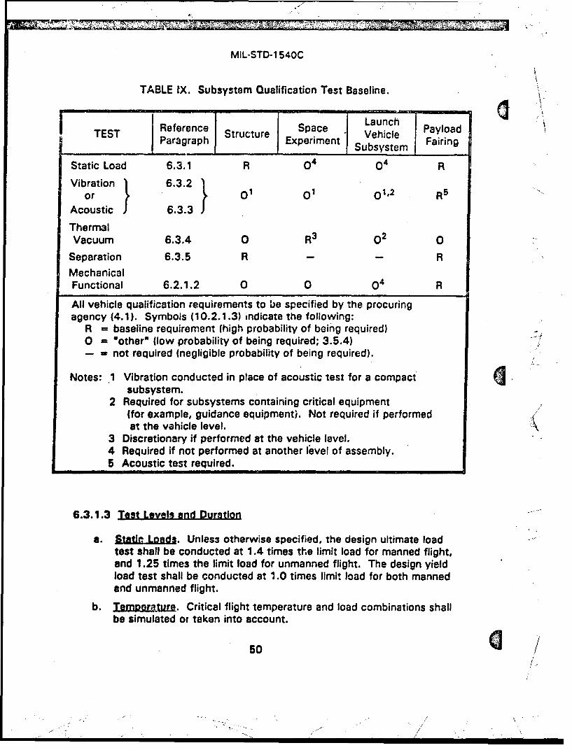
MIL-STD-1 540C
TABLE IX. Subsystem Qualification Test Baseline.
TEST Reference Structure Space Launch PayloadTSParagraph Experiment u Vehicle FairingSubsystem
Static Load 6.3.1 R o4 o4 R
Vibration 6.3.2 1or , 10 12R5 "
Acoustic 6.3.3
ThermalVacuum 6.3.4 0 R3 02 0
Separation 6.3.5 R - - R
MechanicalFunctional 6.2.1.2 0 0 o4 R
All vehicle qualification requirements to be specified by the procuringagency (4.1). Symbols (10.2.1.3) indicate the following:
R = baseline requirement (high probability of being required)0 = 'other" (low probability of being required; 3.5.4)- = not required (negligible probability of being required).
Notes: 1 Vibration conducted in place of acoustic test for a compactsubsystem.
2 Required for subsystems containing critical equipment(for example, guidance equipment). Not required if performed
at the vehicle level. k3 Discretionary if performed at the vehicle level.4 Required if not performed at another level of assembly.5 Acoustic test required.
6.3.1.3 Test Levels and Duration
a. Slatic Loods. Unless otherwise specified, the design ultimate loadtest shall be conducted at 1.4 times the limit load for manned flight,and 1.25 times the limit load for unmanned flight. The design yieldload test shall be conducted at 1.0 times limit load for both mannedand unmanned flight.
b. TeImprtJ~r.. Critical flight temperature and load combinations shallbe simulated or taken into account.
50Sf-
/f
I/
MIL-STD- 1 540C
c. Duration of Loading. Loads shall be applied as closely as practicableto actual flight loading times, with a dweli time not longer than
S)necessary to record test data such as stress, strain, deformation, andtemperature.
6.3.1.A Supolementary Reouirements. Pretest analysis shall be conducted toiden~tify the 5.cations of minimum design margins and associated failure modes thatcorrespond to the selected critical test load conditions. This analysis shall be usedto locate instrumentation, to determine the sequence of loading conditions, and toprovide early indications of anomalous occurrences during the test. This analysisshall also form the basis for judging the adequacy of the test loads. In caseswhere a load or other environment has a relieving, stabilizing, or other beneficialeffect on the structural capability, the minimum, rather than the maximum,expected value shall be used in defining limit-level test conditions. In very complexstructures where simulation of the actual flight loads is extremely difficult, or notfeasible, multiple load cases may be used to exercise all structural zones to designyield and design ultimate loads.
6.3.2 Vibration Test. Subsystem Qualification
6.3.2.1 Pur20se- Same as 6.2.5.1.
6.3.2.2 Test D2escription. Same as 6.2.5.2.
6.3.2.3 Test Levels and Duration. Same as 6.2.5.3.
6.3.2.4 Suctolementary Reoulrements. Same as 6.2.5.4.
6.3.3 Acoustic Test. Subsystem Qualificatlon
6.3.3.1 Pu .2o.s. Same as 6.2.4.1.
6.3.3.2 Test Descr12tton. Same as 6.2.4.2.
6.3.3.3 Test Levels and Duration. Same as 6.2.4.3.
6.3.3.4 Supolementarv Reouirements. Same as 6.2.4.4, as applicable.
6.3.4 Thermal Vacuum Test. Subsystem Qualification
6.3.4.1 E•ow.su. Same as 6.2.9.1..
6.3.4.2 Test Deac,-tloJn. Same as 6.2.9.2.
51
MIL-STD-1 540C
6.3.4.3 Test Levels and Duration. Same as 6.2.9.3.
8.3.4.4 Supplementary Requlrements. Same as 6.2.9.4.
6.3.5 Seopration Test. Srubsvstem Qualificatlon
6.3.5.1 EPuQg.s. The separation test demonstrates the adequacy of theseparation subsystem to meet its performance requirements on such parametersas: separation velocity, acceleration, and angular motion; time to clear andclearances between separating hardware; flexible-body distortion and loads;amount of debris; and explosive-ordnance shock levels. For a payload fairing usinga high-energy separation subsystem, the test also demonstrates the structuralintegrity of the fairing and its generic attachments under the separation shockloads environment. The data from the separation test are also used to validate theanalytical method and basic assumptions used :n the separation analysis. Thevalidated method is then used to verify that requirements are met under worst-caseflight conditions.
6.3.5.2 Test Descrlotion. The test fixtures shall replicate the interfacingstructural sections to simulate the separation subsystem boundary conditionsexisting in the flight article. The remaining boundary conditions for the separatingbodies shall simulate the conditions in flight at separation, unless the use of otherboundary conditions will permit an unambiguous demonstration that subsystemrequirements can be met. The test article shall include all attached flight hardwarethat could pose a debris threat if detached. When ambient atmospheric pressuremay adversely affect the test results, such as for large fairings, the test shall beconducted in a vacuum chamber duplicating the altitude condition encountered inflight at the time of separation. Critical conditions of temperature, pressure, orloading due to acceleration shall be simulated or taken into account. As aminimum, instrumentation shall include high-speed cameras to record the motion ofspecially marked target locations, accelerometers to measure the structuralresponse, and strain gages to verify load levels in structurally critical atachmen~ts.(See 10.3 regarding formation of a Test Evaluation Team.)
6.3.5.3 I.Tst Activations. A separation test shall be conducted todemonstrate that requirements on separation performance parameters are metunder nominal conditions. When critical off-nominal conditions cannot be modeledwith confidence, at least one additional separation test shall be conducted todetermine the effect on the separation process. When force or torque marginrequirements are appropriate, a separate test shall be conducted to demonstratethat the margin is at least 100 percent; for separation subsystems involvingfracture of structural elements, however, the margin demonstrated shall be at least50 percent. In addition, debris risk shall be evaluated by conducting a test
52
MIL-STD-1 540C
encompassing the most severe conditions that can occur in flight, or by includingloads scaled from those measured in tests under nominal conditions.
6.3.5.4 Suoolementary Reauirements. A post-test inspection for debris shall
be conducted on the test article and in the test chamber.
6.4 UNIT QUALIFICATION TESTS
The unit qualification test baseline shall include all the required tests specifiedin Table X. The "other" tests (3.5.4) deemed applicable, and additional specialtests that are conducted as acceptance tests on the unit, shall also be conductedas part of qualification testing. Unit qualification tests shall normally beaccomplished entirely at the unit level. However, in certain circumstances, therequired unit qualification tests may be conducted partially or entiroly at thesubsystem or vehicle levels of assembly. Tests of units such as interconnecttubing, radio-frequency circuits, and wiring harnesses are examples where at leastsome of the tests can usually be accomplished at higher levels of assembly. Ifmoving mechanical assemblies or other units have static or dynamic fluid Interfacesor are pressurized during operation, those conditions should be replicated duringunit qualification testing. Unit performance shall meet the applicable missionrequirements over the entire qualification environmental test range, to themaximum extent practicable. At the end of all required qualification tests, thequalification unit should be disassembled and inspected (4.5).
Where units fall into two or more categories of Table X, the required testsspecified for each category shall be applied. For example, a star sensor may beconsidered to fit both "Electrical and Electronic" and "Optical" categories. Athruster with Integrated valves would be considered to fit both "Thruster' and"Valve" categories.
6.4.1 Functional Test. Unit Qualification
6.4.1.1 Purago.. The functional test verifies that the electrical, optical, andmechanical performance of the unit meets the specified operationa; requirements ofthe unit.
6.4.1.2 Test Descrlotion. Electrical tests shall Include application of expectedvoltages, Impedance, frequencies, pulses, and waveforms at the electricalinterfaces of the unit, Including all redundant circuits. These parameters shall bevaried throughout their specification ranges and the sequences expected in flightoperation. The unit output shall be measured to verify that the unit performs tospecification requirements. Functional performance shall also include electricalcontinuity, stability, response time, alignment, pressure, leakage, or other special
53
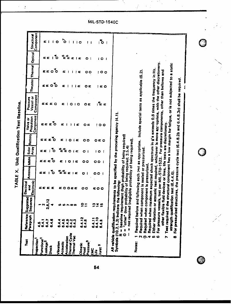
MIL-STD- 1 540C
CL I 1 0 11 10 1I 101O
0 03
w 0 0 cc IIIcc 00 1001 2 C
V .0
.00 Cc2
G;0 0 cc 10 1 w SI.50E
z*(A*1
S .- 02 CLc: b 0 c
j- I=~ Cca O-L Eu
.2 -u' e
V C SIcecc clw1o01gc 00 0=0 .5E Pc
Q. 0 to.
Ir cc : ecc I w 01 10 1 CDO L&~'
2 ~ ~ ~ ~ ~ .i5,c1 =000
at 0, 0. t;..",-
.m c 5 uA14 El '
-j Pw-i 10 10 : I1v 0
0054a
MIL-STD-1 540C
tests that relate to a particular unit configuration. Moving mechanical assembliesshall be tested in the configuration corresponding to the environment being0 simulated and shall be passive or operating corresponding to their state during thecorresponding environmental exposure. Torque versus angle and time versusangle, or equivalent linear measurements for linear devices, shall be made.Functional tests should include stiffness, damping, friction and breakawaycharacteristics, where appropriate. Moving mechanical assemblies that containredundancy in their design shall demonstrate required performance in eachredundant mode of operation during the test.
6.4.1.3 Suoolementarv Reguirements. Functional or monitoring tests shall beconducted before, during, and after each of the unit tests to detect equipmentanomalies and to assure that performance meets specification requirements.
6.4.2 Thermal Cycle Test. Electrical and Electronic Unit Qualification
6.4.2.1 Purgoset. The thermal cycle test demonstrates the ability of electricaland electronic units to operate over the qualification temperature range and toendure the thermal cycle testing imposed during acceptance testing.
6.4.2.2 Test Description. With the unit operating (power on) and whileperceptive parameters are being monitored, the test shall follow the temperatureprofile in Figure 1. The test control temperature shall be measured at arepresentative location on the unit, such as at the mounting point on the
0 baseplate. Each time the control temperature has stabilized (3.5.7) at the hottemperature, the unit shall be turned off and then hot started. Then, with the unitoperating, the control temperature shall be reduced to the cold temperature and theunit turned off. To aid in reaching the cold temperature, the unit may be poweredoff when the temperature of the unit is at least 100C colder than its minimumexpected temperature (3.3.1). After the unit has stabilized at the coldtemperature, the unit shall be cold started. T.',mperature change from ambient tohot, to cold, and return to ambient constitutas one thermal cycle.
6.4.2.3 Test Levels and Duration
a. Pressure and Humidity. Ambient pressure is normally used; however,the thermal cycle test may be conducted at reduced pressure,including vacuum conditions. When unsealed units are being tested,provisions shall be taken to preclude condensation on and, within theunit at low temperature. For example, the chamber may b~floodedwith dry air or nitrogen. Also, the last half cycle shall be hpt(Figure 1).
55
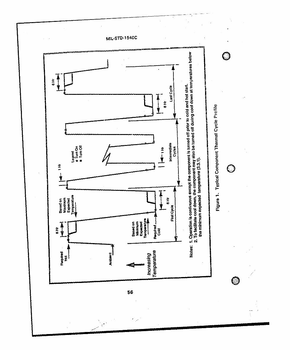
MIL-STD-1 540C
L (A 0
00 s
E C!
0
0 ý0
00
56.
MIL-STD-1540C
b. ITe[ tgJ.. The unit temperature shall reach the qualification hottemperature, 10'C above the acceptance hot temperature (7.1.1),0 during the hot half cycle; the qualification cold temperature, 10°Cbelow the acceptance cold temperaturp, during the cold half cycle(Table V). For units exposed to cryogenic temperatures in service,qualification margins shall be prescribed on an individual basis. Thetransitions between hot and cold should be at an average rate of 3 to50C per minute, and shall not be slower than 1°C per minute.
c. Duration. Table VI shows the number of qualification thermal cyclesrequired for various situations. The last 4 thermal cycles shall befailure free. Thermal soak durations (3.5.10) shall be a minimum of 6hours at the hot and 6 hours at the cold temperature during the firstand last cycle (Figure 1). Intermediate cycles shall have at least 1-hoursoaks at the hot and cold temperatures. During thermal soaks, theunit shall be turned off until the temperature stabilizes (3.5.7) andthen turned on, remaining on until the next soak period off-onsequence. Measurement of thermal soak durations shall begin at thetime oa unit turn-on (Figure 1).
6.4.2.4 u1nmfelntf•J l3 Reguirements. The requirements of the thermal cycletest may be satisfied by extending the thermal vacuum test of 6.4.3, to achievethe number of cycles required to meet the requirements of Table VI. Selection ofsuch an alternative requires that the applicable acceptance test be carried out inthe same fashion. Functional tests shall be conducted after the unit temperatureshave stabilized at the hot and cold temperatures during the first and last thermalcycle, and after return to ambient. During the remainder of the test, electrical andelectronic units, including all redundant circuits and paths, shall be cycled throughvarious operational modes. Oerceptive parameters shall be monitored for failuresand Intermittents to the ma. imum extent practicable. Units shall meet theirperformance requirements within specification over the maximum expectedtemperature range (3.3.1) extended at both temperature extremes by 100C. Fordigital units, such as computers, the final thermal cycle should employ asufficiently slow temperature transition to permit a complete functional check to berepeated at essentially all temperatures.
Moisture condensation inside of electrical or electronic units shall beprevented. Condensation is also minimized by requiring the first and last half cycleto be hot (Figure 1).
6.4.3 Thermal Vacuum Test. Unit Qualificatgon
6.4.3.1 PEurwgz. The thermal vacuum test demonstrates the ability of theunit to perform In the qualification thermal vacuum environment and to endure the
S57
MIL-STD- 1 540C
thermal vacuum testing imposed on flight units during acceptance testing. It alsoserves to verify the unit thermal design.
6.4.3.2 Test D2escrIption. The unit shall be mounted In a vacuum chamber ona thermally controlled heat sink or in a manner similar to its actual installation inthe vehicle. The utit surface finishes, which affect radiative heat transfer orcontact conductance, shall be thermally equivalent to those on the flight units. Forunits designed to reject their waste heat through the baseplate, a controltemperature sensor shall be attached either to the unit baseplate or the heat sink.The location shall be chosen to correspond as closely as possible to thetemperature limits used in the vehicle thermal design analysis or applicableunit-to-vehicle interface criteria. For components cnoled primarily by radiation, arepresentative location on the unit case shall similarly be chosen. The unit heattransfer to the thermally controlled heat sink and the radiation heat transfer to theenvironment shall be controlled to the same proportions as calculated for the flightenvironment. During testing of radio-frequency (rf) equipment with a possibility ofmultipaction, a space nuclear radiation environment shall be simulated by agamma-ray or x-ray source at 4 rads per hour.
The chamber pressure shall be reduced to the required vacuum conditions.Units that are required to operate during ascent shall be operating and monitoredfor arcing and corona during the reduction of pressure to the specified lowestlevels and during the early phase of vacuum operation. At vacuum pressuresbelow 133 millipascals (10-3 Torr), units shall be monitored as appropriate to also 0assure that multipacting does not occur. Units that Jo not operate during launchshall have electrical power applied after the test pressure level has been reached.
A thermal cycle begins with the conductive or radiant sources and sinks atambient temperature. With the unit operating and while perceptive parameters arebeing monitored, the unit temperature is raised to the specified hot temperatureand maintained. All electrical and electronic units that operate in orbit shall beturned off, then hot started after a duration sufficient to ensure the unit internaltemperature has stabilized (3.5.7), and then functionally tested. With the unitoperating, the component temperature chall be reduced to the specified coldtemperature. To aid In reaching the cold temperature, the unit may be powered offwhen the temperature of the unit is at least 10C colder than its minimumexpected temperature (3.3.1). After the unit temperature has reached thespecified cold temperature, the unit shall be turned off (if not previously turned offduring the transition) until the internal temperature stabilizes (3.5.7) and then coldstarted and functionally tested, continuing to maintain the unit at the specifiedtemperature until the end of the soak. The temperature of the sinks shall then beraised to ambient conditions. This constitutes one complete thermal cycle.
058
MIL-STD-1540C
6.4.3.3 Test Levels and Duration
a. Pressu For units required to operate during ascent, the time forreduction of chamber pressure from ambient to 20 pascals (0.15 Torr)shall be at least 10 minutes to allow sufficient time in the region ofcritical pressure. The pressure shall be further reduced from 20pascals for operating equipment, or from atmospheric for equipmentwhich does not operate during ascent, to 13.3 millipascals (10-4 Torr)at a rate that simulates the ascent profile to the extent practicable.For launch vehicle units, the vacuum pressure shall be modified toreflect an altitude consistent with the maximum service altitude.
b. TJmpera•utr. The unit hot and cold temperatures shall be the sameas those specified in 6.4.2.3b. An exception is made for a propulsionunit In contact with propellant for which the cold temperature shall belimited to 30C above the propellant freezing temperature. Thetransitions between hot and cold should be at an average rate greaterthan 1 0C per minu,a.
c. Duration. The number of thermal cycles shall be as given in Table VI.Thermal soak durations (3.5.10) shall be a minimum of 6 hours at thehot and 6 hours at the cold temperature during the first and last cycle.Intermediate cycles shall have at least 1-hour soaks at the hot andcold temperatures with power turned on. Measurement of thermalsoak durations shall begin at the time of unit turn-on (Figure 1).
6.4.3.4 Sunolementarv Renuirements. The 25-cycle test is applicable to unitscontaining electrical or electronic elements where environmental stress screening isimposed for acceptance testing. For nonelectrical and nonelectronic units, the 6-cycle test applies (Table VIl.
Functional tests shcll be conducted after unit temperatures have stabilized atthe hot and cold temperatures during the first and last cycle, and after return ofthe unit to ambient temperature in vacuum. During the remainder of the test,electrical and electronic units, including all redundant circuits and paths, shall becycled through various operational modes. Perceptive parameters shall bemonitored for failures and intermittents to the maximum extent practicable. Unitsshall meet their performance requirements within specifications over the maximumexpected temperature range extended by 100C at the hot and cold limits.
For moving mechanical assemblies, performance parameters (such as currentdraw, resistance torque or force, actuation time, velocity or acceleration) shall bemonitored. Where practicable, force or torque margins shali be determined onmoving mechanical assemblies at the temperature extremes. Where this is not
59
-'- -_ /- 1-..
MIL-STD-1 540CC
practicable, minimum acceptable force or torque margin shall be demronstrated.Compatibility with operational fluids shall be verified at test temperature extremesfor valves, propulsion units, and other units as appropriate.
6.4.4 Vibration Test. Unit Qulfcto
6.4.4.1 Pupoe The vibralon test demonstrates the ability of the unit toendure a maximum duration of correcponding acceptance testing and then meetrequirements during and after exposure to the extreme expected dynamicenvironment in flight (3.3.5).
6.4.4.2 Tet1asdcxiptn. The unit shall be mounted to a fixture through thenormal mounting points of the unit. The same test fixture should be used in thequalification and acceptance vibration tests. Attached wiring harnesses andhydraulic and pneumatic lines up to the first attachment point, instrumentation,and other connecting items should be included as in the flight configuration. Sucha configuration shall be required when units that employ shock or vibrationisolators are tested on their isolators. The suitability of the fixture and test controlmeans shall have been established prior to the qualification testing (6.4.4.5). Theunit shall be tested in eafch of 3 orthogonal axes. Units required to operate underpressure during ascent shall be. pressurized to simulate flight conditions, fromstructural and leakage standpoints, and monitored for pressure decay. Unitsdesigned for operation during ascent, and whose maximum or minimum expectedtemperatures fall outside the normal temperature range (7.1.1), are candidates forQcombined vibration and temperature testing. When such testing is employed, unitsshall be conditioned to be as close to the worst-case flight temperature as ispracticable and monitored for temperature during vibration exposure.
Units mounted on shock or vibration isolators shall typically require vibrationtesting at qualification levels in two configurations. A first configuration is withthe unit hard-mounted to qualify for the accepta nce- level testing if, as is typical,the acceptance testing. is performed without the isolators present. The secondconfiguration Is with the unit mounted on -the isolators to qualify for the flightenvironment. The unit shall be mounted on isolators of the same lot as those usedin service, If practicable. Units mounted on isolators shall be controlled at thelocations where the Isolators are attached to the structure. Hard-mounted unitsshall be controlled at the unit mounting attachments.
6.4.4.3 Test Leveal and Quratlon2. The test shall be conducted per 6.4.4. Forhard-mounted units, a typical version of the test involves acceleratedacceptance-level testing per 6.1.4.2 and applies the qualification level spectrum for3 minutes per axis. This is bas6d on' a qualification margin of 6 dB, a maximum of6 minutes of accumulated acceptance testing on a flight unit, and a fatigueequivalent duration in flight (3.3.3) of not greater than 15 seconds. Operating time
60 c
A
MIL-STD-1540C
should be divided approximately equally between redundant functions. Wheninsufficient test time is available at the full test level to test redundant circuits,functions, and modes, extended testing using a spectrum no lower than 6 dBbelow the qualification spectrum shall be conducted as necessary to completefunctional testing.
6.4.4.4 Suoolementarv Reoulrerments. During the test, all electrical andelectronic units shall be electrically energized and functionally sequenced throughvarious operational modes to the maximum extent practicable. This includes allredundant circuits, and all circuits that do not operate during launch. Severalperceptive parameters shall be monitored for failures or interrittents during thetest. Continuous monitoring of the unit, including the main bus by a powertransient monitoring device, shall be provided to detect intermittent failures. Whennecessary to prevent unrealistic input forces or unit responses for units whosemass exceeds 23 kilograms (50 pounds), the spectrum may be limited or notched,but not below the minimum test spectrum for a unit (7.1.3). The vibration testdoes not apply to a unit having a large surface causing its vibration response to bedue predominantly to direct acoustic excitation (6.4.5).
6.4.4.5 Fixture Evaluation. The vibration fixture shall be verified by test touniformly impart motion to the unit under test and to limit the energy transfer fromthe test axis to the other two orthogonal axes (crosstalk). The crosstalk levelsshould be lower than the input for the respeetive axis. In 1/6-octave bands above1000 Hz, exceedances of up to 3 dB are allowed provided that the sum of theirbandwidths does not exceed 300 Hz in a cross axis. The dynamic testconfiguration (fixture and unit) shall be evaluated for crosstalk before testing toqualification levels.
6.4.4.6 Soecial Considerations for Structural Unlta. Vibration acceptancetests of structural units are normally not conducted beiýause the process controls,inspections, and proof testing that are implemented are sufficient to assureperformance and quality. However, to demonstrate structural integrity ofstructural units having critical fatigue-type modes of failure, with a low fatiguemargin, a vibration qualification test shall be conducted. The test duration shall be4 times the fatigue equivalent duration in flight at the extreme expected level(3.3.5). When a structural unit is not subjected to a static strength qualificationtest, a brief random vibration qualification test shall be conducted with anexposure to 3 dB above the extreme expected level. The duration shall be thatnecessary to achieve a steady-state response, but not less than 10 seconds, todemonstrate that ultimate strength requirements are satisfied.
61
MIL-STD-1 540C
6.4.5 Acoustic Test. Unit Qualification
6.4.5.1 P . The acoustic test demonstrates the ability of a unit havinglarge surfaces, whose vibration response is due Dredominantly to direct acousticexcitations, to endure a maximum duration of acoustic acceptance testing and thenmeet requirements during and after exposure to the extreme expected dynamicenvironment in flight (3.3.4). For such units, the acoustic test shall be conductedand the vibration test (6.4.4) is discretionary.
6.4.5.2 Test Description. The unit in its ascent configuration shall beinstalled in an acoustic test facility capable of generatiro sound fields or fluctuatingsurface pressures that induce unit vibration environments sufficient for unitqualification. The unit should be mounted on a flight-type support structure orreasonable simulation thereof. Significant fluid and pressure conditions shall bereplicated to the extent practicable. Appropriate dynamic instrumentation shall beinstalled to measure vibration responses. Control microphones shall be placed at aminimum of 4 well-separated locations at one half the distance from the test articleto the nearest chamber wall, but no closer than 0.5 meter (20 inches) to both thetest article surface and the chamber wall.
6.4.5.3 Test Level and Duration. Same as 6.2.4.3 except the qualificationtest duration shall be 3 minutes based on a maximum of 6 minutes of accumulate6acceptance testing on a flight unit.
6.4.5.4 Suoolementarv Reauirements. Same as 6.2.4.4.
6.4.6 Shock Test. Unit Qualification_
6.4.6.1 Purose. The shock test demonstrates the capability of the unit tomeet requirements during and after exposure to the extreme expected shockenvironment in flight (3.3.7).
6.4.6.2 Test Descriotion. The unit shall be mounted to a fixture through thenormal mounting points of the unit. The same test fixture should be used in thequalification and acceptance shock tests. If shock Isolators are to be used inservice, they shall be installed. The selected test method shall be capable ofmeeting the required shock spectrum with a transient that has a durationcomparable to the duration of the expec•,ted shock in flight. A mounting of the uniton actual or dynamically similar structure provides a more realistic test than does amounting on a rigid structure such as a shaker armature or slip table. Sufficientprior development of the tent mechanist shall have been carried out to validate theproposed test method before testing qualification hardware. The test environmentshall comply with the following conditions:
620
M. - \' ,\ 2
MIL-STD-1540C
a. A transient having the prescribed shock spectrum can be generatedwithin specified tolerances.
b. The applied shock transient provides a-simultaneous application of tfrequency components as opposed to a serial application. Toward ttend, it shall be a goal for the duration of the shock transient toapproximate the duration of the service shock event. In general, th(duration of the shock employed for the shock spectrum analysis shanot exceed 20 milliseconds.
6.4.6.3 Test Level and Exposure. The shock spectrum in each direction alo
each of the 3 orthogonal axes shall be at least the qualification level for that"direction. For vibration or shock isolated units, the lower frequency limit of theresponse spectrum shall be below 0.7 times the natural frequency of the Isolatedun't. A sufficient number of shocks shall be imposed to meet the amplitude crite
in both directions of each of the 3 orthogonal axes at least 3 times the number osignificant events 'at that unit location. A significant event for the unit beingqualified is one that produces a maximum expected shock spectrum within 6 dBthe envelope of maximum expected spectra (3.3.7) from all events.
6.4.6.4 SuDolementary Reaulregments. Electrical and electronic units,including redundant circuits, shall be energized and monitored to the maximumextent practicable, including those that are not normally operating during the
j service shock. A functional test shall be performed before and after all shocktests, and several perceptive parameters monitored during the shocks to evaluateperformance and to detect any failures. Relays shall not transfer and shall notchatter in excess of specification limits during the shock test.
A shock qualification test is not required along any axis for which both thefollowing are satisfied:
a. The qualification random vibration test spectrum when converted toan equivalent shock response spectrum (3-sigma response forQ = 10) exceeds the qualification shock spectrum requirement at al!frequencies below 2000 Hz.
b. The maximum expected shock spectrum above 2000 Hz does notexceed g values equal to 0.8 times the frequency in Hz at allfrequencies above 2000 Hz, corresponding to a velocity of 1.27meters/second (50 inches/second).
O :63
... . j" °' 2 2i* , ,. /22* "' . "','
MIL-STD-1 540C
6.4.7 Leakaoe Test. Unit Qualification
6.4.7.1 Eroq. The leakage test demonstrates the capability of pressurizedcomponents and hermetically sea!ed units to meet the specified design leakage raterequirements.
6.4.7.2 Test Descriotion. An acceptable leak rate to meet missionrequirements is based upon development tests and appropriate analyses. Anacceptable measurement technique is one that accounts for leak rate variationswith differential pressure and hot and cold temperatures and has the requiredthreshold, resolution, and accuracy to detect any leakage equal to or greater thanthe maximum acceptable leak rate. Consideration should be given to testing unitsat differential pressures greater or less than the maximum or minimum operatingdifferential pressure to provide some assurance of a qualification margin forleakage. It appropriate, the leak rate test shall be made at qualification hot andcold temperatures with the representative fluid to account for geometry alterationsand viscosity changes.
6.4.7.3 Test Level and Duration. Unless otherwise specified, the leakagetests shall be performed with the unit pressurized at the maximum differentialoperating pressure, as well as at the minimum differential operating pressure if theseals are dependent upon pressure for proper sealing. The test duration shall besufficient to detect any significant leakage. 4
6.4.8 Pressure Test. Unit Qualification
6.4.8.1 EPurog.. The pressure test demonstrates adequate margin, so thatstructural failure does not occur before the design burst pressure is reached, orexcessive deformation does not occur at the maximum expected operatingpressure (MEOP).
6.4.8.2 Test Descriotion
a. Proof Pressure Test. For items such as pressurized structures andpressure components, a proof test with a minimum of 1 cycle of proofpressure shall be conducted. Evidence of either leakage, a permanentset or distortion that exceeds a drawing tolerance, or failure of anykind shall constitute failure to pass the test.
b. Pressure Cycle Test. For pressurized structures and pressure vessels,a pressure cycle test shall be conducted. Requirements for applicationof external loads in combination with internal pressures during testingshall be evaluated based on the relative magnitude and on thedestabilizing effect of stresses due to the external load. If limit
64
MIL-STD-1 540C
combined tensile stresses are enveloped by the test pressure stress,the application of external load is not required.
C. BurstITx. The pressure shall be increased to the design burstpressure, while simultaneously applying the ultimate external load(s),if appropri3te. The internal pressure shall be applied at a sufficientlyslow rate that dynamic stresses are negligible. For pressure vessels,after demonstrating no burst at the design burst pressure, thepressure shall be increased to actual burst of the vessel, and theactual burst pressure shall be recorded.
6.4.8.3 Test Leve~s and DurationsL
a. Temgerature and Humidity. The test temperature and humidityconditions shall be consistent with the critical-use temperature andhumidity. As an alternative, tests may be conducted at ambientconditions if the test pressures are suitably adjusted to account fcrtemperature and humidity effects on material strength and fracturetoughness.
b. Pro.of P . Unless otherwise specified, the minimum proofpressure for pressurized structures shall be 1.1 times the MEOP. Forpressure vessels, and other pressure components such as !ines and
C fittings, the minimum proof pressure shall comply with therequirements specified in MIL-STD-1 522. The pressure shall bemaintained for a time just sufficient to assure that the proper pressur,was achieved. Except that for pressure vessels, the hold time shall ba minimum of 5 minutes unless otherwise specified.
c. Pesr .l,. Unless otherwise specified, the peak pressure forpressurized structures shall equal the MEOP during each cycle, andthe number of cycles shall be 4 times the predicted number ofoperating cycles or 50 cycles, whichever is greater. For pressurevessels, the test shall comply with the requirements specified inMIL-STD-1522.
d. Burt Pressure. Unless otherwise specified, the minimum design bunpressure for pressurized structures shall be 1.25 times the MEOP. F(pressure vessels and pressure components, the minimum design burspressure shall comply with MIL-STD-1522. The design burst pressurshall be maintained for a period of time just sufficient to assure thatthe proper pressure was achieved.
o 65
MIL-STD-1 540C
6.4.8.4 Sug~lemertary Reautrements. Applicable safety standards shall befollowed in conducting all tests. Unless otherwise specified, the qualificationtesting of pressure vessels shall include a demonstration of a leak-before-burst(LBB) failure mode using pre-flawed specimens as specified in MIL-STD-1522. TheLBB pressure test may be omitted if availabla material data are directly applicableto be used for an analytical demonstration of the leak-before-burst failure mode.
6.4.9 Accelerrtion Test. Unit Qualification
6.4.9.1 Puwrgzo.. The acceleration test demonstrates the capability of theunit to withstand or, if appropriate, to operate in the qualification level accelerationenvironment.
6.4.9.2 Test Descriotion. The unit shall be attached, as it is during flight, to atest fixture and subjected to acceleration in appropriate directions. The specifiedaccelerations apply to the center of gravity of the test item. If a centrifuge isused, the arm (measured to the geometric center of the test item) should be atleast 5 times the dimension of the test Item measured along the arm. Theacceleration gradient across the test item should not result in accelerations that fallbelow the qualification level on any critical member of the test item. In addition,any over-test condition should be minimized to prevent unnecessary risk to the testarticle. Inertial units such as gyros and platforms may require counter-rotatingfixtures on the centrifuge arm.
6.4.9.3 Test Levels and Duration
a. Acceleration Level. The test acceleration level shall be at least 1.25times the maximum predicted acceleration (3.4.8) for each directionof test. The factor shall be 1.4 for manned flight.
b. Duration. Unless otherwise specified, the test duration shall be atleast 5 minutes for each direction of test.
6.4.9.4 Sugolementarv Requirements. If the unit is to be mounted on shockor vibration isolators in the vehicle, the unit should be mounted on these isolatorsduring the qualification test.
6.4.10 Life Test. Unit Qualification
6.4.10.1 PurRose. The life test applies to units that may have a wearout,drift, or fatigue-type failure mode, or a performance degradation, such as batteries.The test demonstrates that the units have the capability to perform withinspecification limita for the maximum duration or cycles of operation duringrepeated ground testing and in flight.
66
MIL-STD-1540C
6.4.10.2 Test Descriotion. One or more units shall be operated underconditions that simulate their service conditions. These conditions shall be0 selected for consistency with end-use requirements and the significant lifecharacteristics of the particular unit. Typical environments are ambient, thermal,and thermal vacuum to evaluate wearout and drift failure modes; and pressure,therr, al, and vibration to evaluate fatigue-type failure modes. The test shall bedesigned to demonstrate the ability of the unit to withstand the maximumoperating time and the maximum number of operational cycles predicted during itsservice life (3.5.6) with a suitable margin.
6.4.10.3 Test Levels and Durations.
a. Pressjjj. For pressurized structures and pressure vessels, thepressure level shall be that specified in 6.4.8.3c. For other units,ambient pressure shall be used except where degradation due to avacuum environment may be anticipated, such as for some unsealedunits. In those cases, a pressure of 13.3 millipascals (104 Torr) orless shall be used.
b. Environmental Levels. The extreme expected environmental levelsshall be used. Higher levels may be used to accelerate the life testing,provided that the resulting increase in the rate of degradation is wellestablished and that unrealistic failure modes are not introduced.
c. Duration. For pressurized structures and pressure vessels, theduration shall be that specified in 6.4.8.3c. For other units, the totaloperating time or number of operational cycles shall be at least 2times that predicted during the service life (3.5.6), including groundtesting, in order to demonstrate an adequate margin. For a structuralcomponent having a fatigue-type failure mode that has not beensubjected to a vibration qualification test, the test duration shall be atleast 4 times the specified service life.
d. Functional Duty Cycle. Complete functional tests shall be conductedbefore the test begins and after completion of the test. During the lifetest, functional tests shall be conducted in sufficient detail, and atsufficiently short Intervals, so as to establish trends.
6.4.10.4 Supolementarv Reauirements. For statistically-based life tests, theduration is dependent upon the number of samples, confidence, and reliability to bedemonstrated.. The mechanisms in each unit that are subjected to wearout shouldbe separately tested. For these mechanisms, the duration of the life test shouldassure with high confidence that the mechanisms will not wear out during theirservice life. At the end of the life test, mechanisms and moving mechanical
67
MIL-STD-1 540C
assemblies shall be disassembled and inspected for anomalous conditions. Thehardware may be disassembled and inspected earlier if warranted. The criticalareas of parts that may be subject to fatigu. failure shall be inspected to determinetheir integrity.
6.4.11 Electromaanetic Compatibillty (EMC) Test. Unit Qualification
6.4.11.1 Pl.os.. The electromagnetic compatibility test shall demonstratethat the electromagnetic interference characteristics (emission and susceptibility) ofthe unit, under normal operating conditions, do not result in malfunction of theunit. It also demonstrates that the unit does not emit, radiate, or conductinterference which could result in malfunction of other units.
6.4.11.2 Test Description. The test shall be conducted in accordance withthe requirements of MIL-STD-1541. An evaluation shall be made of each unit todetermine which tests shall be performed as the baseline requirements.
6.4.12 Climatic Tests. Unit Qualification
6.4.12.1 Pur.pos. These tests demonstrate that the unit is capable ofsurviving exposure to various climatic conditions without excessive degradation, oroperating during exposure, as applicable. Exposure conditions include thoseimposed upon the unit during fabrication, test, shipment, storage, preparation forlaunch, launch itself, and reentry if applicable. These can include such conditions 4as humidity, sand and dust, rain, salt fog, and explosive atmosphere. Degradationdue to fungus, ozone, and sunshine shall be verified by design and materialselection.
It is the intent that environmental design of flight hardware not beunnecessarily driven by terrestrial natural environments. To the greatest extentfeasible, the flight hardware shall be protected from the potentially degradingeffects of extreme terrestrial natural environments by procedural controls andspecial support equipment. Only those environments that cannot be controlledneed be considered in the design and testing.
6.4.12.2 Humidity Test. Unit Qualification
6.4.12.2.1 Puroose. The humidity test demonstrates that the unit is capableof surviving or operating in, if applicable, warm humid environments. In the caseswhere exposure is controlled throughout the life cycle to conditions with less than55-percent relative humidity, and the temperature changes do not create conditionswhere condensation occurs on the hardware, then verification by test is notrequired.
"68
/
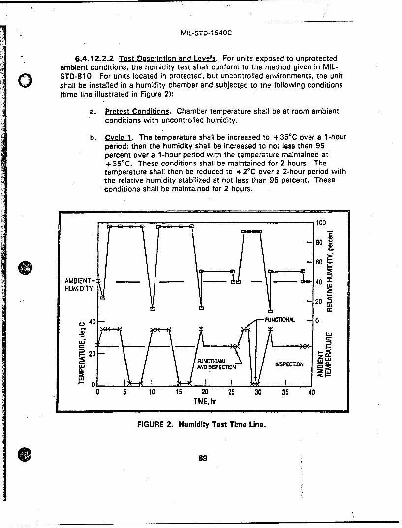
MIL-STD-1 540C
6.4.12.2.2 Test Description end Levels. For units exposed to unprotectedambient conditions, the humidity test shall conform to the method given in MIL-STD-810. For units located in protected, but uncontrolled environments, the unitshall be installed in a humidity chamber and subjected to the following conditions(time line illustrated in Figure 2):
a. Pretest Conditions. Chamber temperature shall be at room ambientconditions with uncontrolled humidity.
b. Cycle 1. The temperature shall be increased to +35 0 C over a 1-hourperiod; then the humidity shall be increased to not less than 95percent over a 1-hour period with the temperature maintained at+35 0 C. These conditions shall be maintained for 2 hours. Thetemperature shall then be reduced to + 20C over a 2-hour period withthe relative humidity stabilized at not less than 95 percent. Theseconditions shall be maintained for 2 hours.
100
- 80
- 60~- - -- o40AMOIENT-t 4HUMIDITY
- 20~
o40- FUNCTIONAL -I0.
-20 ,FUNTOA wU=V ý INPET C3 CL /' "
ILAND DWSPECTION U4PETI9 0
0 5 10 15 20 25 30 35 40
TIME, hr
FIGURE 2. Humidity Test Time Line.
69
MIL-STD-1 540C
c. C . Cycle 1 shall be repeated except that the temperature shallbe Increased from + 20C to + 35 0C over a 2-hour period; moisture isnot added to the chamber until + 350C is reached.
d. 3. The chamber temperature shall be increased to +35 0 C overa 2-hour period without adding any moisture to the chamber. Thetest unit shall then be dried with air at room temperature and 50-percent maximum relative humidity by blowing air through thechamber for 6 hours. The volume of air used per minute shall beequal to 1 to 3 times the test chamber volume. A suitable containermay be used in place of the test chamber for drying the test unit.
e. Cycle4. If it had been removed, the unit shall be placed back in thetest chamber and the temperature increased to + 350 C and therelative humidity increased to 90 percent over a 1-hour period; andthese conditions shall be maintained for at least 1 hour. Thetemperature shall then be reduced to + 20 C over a 1-hour period withthe relative humidity stabilized at 90 percent; and these conditionsshall be maintained for at least 1 hour. A drying cycle should follow(see Cycle 3).
6.4.12.2.3 Sugolementary Reguirements. The unit shall be functionallytested prior to the test and at the end of Cycle 3 (within 2 hours after the drying)and visually inspected fcr deterioration or damage. The unit shall be functionallytested during the Cycle 4 periods of stability, after the 1-hour period to reach+:!5°C and 90-percent relative humidity, and again after the 1-hour period toreach the +2°C and 90-percent relative humidity.
6.4.12.3 Sand and Dust Test Unit Qualification
6.4.12.3.1 Ejmo.se. The sand and dust test is conducted to determine theresistance of units to blowing fine sand and dust particles. This test shall not berequired for units protected from sand and dust by contamination control,protective shipping and storage containers, or covers. However, in those cases,rain testing demonstrating the adequacy ot the protective shelters, shipping andstorage containers, or covers, as applicable, may be required instead of a test ofthe unit itself.
6.4.12.3.2 Test De-crnltIon. The test requirements for the sand and dusttest shall conform to the method given in MIL-STD-810.
70
MIL-STD-1 540C
6.4.12.4 Rain Test. Unit Q jfjcalu o
6.4.12.4.1 P . The rain test shall be conducted to determine theresistance of units to rain. Units protected from rain by protective shelters,shipping and storage containers, or covers, shall not require verification by test.
6.4.12.4.2 Test Description. Buildup of the unit, shelter, container, or thecover being tested shall be representative of the actual fielded configurationwithout any duct tape or temporary sealants. The initial temperature differencebetween the test item and the spray water shall be a minimum of 100C. Fortemperature-controlled containers, the temperature difference between the testitem and the spray water shall at least be that between the maximum controltemperature and the coldest rain condition In the field. Nozzles used shall producea square spray pattern or other overlapping pattern (for maximum surfacecoverage) and droplet size predominantly in the 2 to 4.5 millimeter range atapproximately 375 kilopascals gage pressure (40 psig). At least one nozzle shallbe used for each approximately 0.5 square meter (6 ft2) of surface area and eachnozzle shall be positioned at 0.5 meter (20 inches) from the test surface. Allexposed faces shall be sprayed for at least 40 minutes. The interior shall beinspected for water penetration at the end of each 40-minute exposure. Evidenceof water penetration shall constitute a failure.
6.4.12.5 Salt Fog Test. Unit Qualification
6.4.12.5.1 Purgo.. The salt fog test is used to demonstrate the resistanceof the unit to the effects of a salt spray atmosphere. The salt fog test is notrequired if the flight hardware is protected against the salt fog environment bysuitable preservation means and protective shipping and storage containers.
6.4.12.5.2 Test Descri2tion. The requirements for the salt fog test shall
conform to the method given in MIL-STD-810.
6.4.12.6 Exolosive Atmosohere Test. Unit Qualification
6.4.12.6.1 ujQ9.. The explosive atmosphere test is conducted todemonstrate unit operability in an ignitable fuel-air mixture without igniting themixture.
6.4.12.6.2 Test Descrlotion. The test requirements for the explosiveatmosphere test shall conform to the method given in MIL-STD-810.
.71
MIL*STD-l 540C
SECTION 7
ACCEPTANCE TESTS0
7.1 GEKERAL ACCEPTANCE TEST REQUIREMENTS
Acceptance tests shall be conducted as required to demonstrate theacceptability of each deliverable item. The tests shall demonstrate conformance tospecification requirements and provide quality-control assurance againstworkmanship or mateeial deficiencies. Acceptance testing is intended to stressscreen items to precipitate incipient failures due to latent defects in parts,materials, and workmanship. However, the testing shall not create conditions thatexceed appropriate design safety margins or cause unrealistic modes of failure. Ifthe equipment Is to be used by more than one program or in different vehiclelocations, the acceptance test conditions should envelope those of the variousprograms or vehicle locations involved. Typical acceptance test levels anddurations are summarized in Table Xl, and arm detailed in subsequent p aragraphs.
The test baseline shall be tailored for each program, giving consideration toboth the required end other tests (3.5.4). For special~items, such as some taperecorders and certain batteries, the specified acceptance test environments wouldresult in physical deterioration of materials or other damage. In those cases, lesssevere acceptance test environments that still satisfy the system operationalrequirements shall be used.
7.1.1 Temoerature Range and Number of Thgrmal Cycles. Acceptance Tests.Two requirements on the unit acceptance temperature range (Figure 3) are:
a. The range shall encompass the maximum and minimum expectedtemperatures (3.3.1).
b. The range should be as large as practicable to meet environmentalstress screening purposes. A range of 105 0C is recommended, and Isthe basis used in Tables V and VI.
For units, the range from -44 to + 61 *C is recommended If requirement *a" Issatisfied. The number of cycles shall be In compliance with Table VI. If this105c0C temperature range, p'us the 100C hot and cold extension for qualification,gives rise to unrealistic failure modes or unrealistic design requirements, the rangemay be shifted or reduced to the extent necessary. To compensate for a reducedrange, the number of thermal cycles for acceptance tests shall then be increasedper note 3 of Table VI. For units exposed to cryogenic temperatures, acceptancetemperature limits shall encompass the highest and lowest temperatures withappropriate uncertainty margins (Table 11). For units which do not contain electrical
72
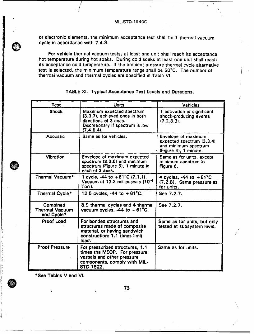
/
MIL-STD-1 540C
or electronic eOements, the minimum acceptance test shall be 1 thermal vacuumo cycle in accordance with 7.4.3.
For vehicle thermal vacuum tests, at least one unit shall reach its acceptancehot temperature during hot soaks. During cold soaks at least one unit shall reachits acceptance cold temperature. If the ambient pressure thermal cycle alternativetest is selected, the minimum temperature range shall be 50 0 C. The number ofthermal vacuum and thermal cycles are specified in Table VI.
TABLE X1. Typical Acceptance Test Levels and Durations.
Test Units Vehicles
Shock Maximum expected spectrum 1 activation of significant(3.3.7), achieved once in both shock-producing eventsdirections of 3 axes. (7.2.3.3).Discretionary if spectrum is low
i_ _(7.4.6.4).
Acoustic Same as for vehicles. Envelope of maximumexpected spectrum (3.3.4)and minimum spectrum(Figure 4), 1 minute.
Vibration Envelope of maximum expected Same as for units, exceptsp.,ctrum (3.3.5) and minimum minimum spectrum inspectrum (Figure 5). 1 minute in Figure 6.
_ _ _ each of 3 axes.Thermal Vacuumr 1 cycle, -44 to +61 0 C (7.1.1). 4 cycles, -44 to +61°C
Vacuum at 13.3 millipascals (10-4 (7.2.8). Same pressure asTorr). for units.
Thermal Cycle* 12.5 cycles, -44 to + 610 C. See 7.2.7.
Combined 8.U thermal cycles and 4 thermal See 7.2.7.Thermal Vacuum vacuum cycles, -44 to + 61 0C.
and Cycle* ......Proof Load For bonded structures and Same as for units, but only
structures made of composite tested at subsystem level.material, or having sandwichconstruction: 1.1 times limitload.
Proof Pressure For pressurized structures, 1.1 Same as for %inits.times the MEOP. For pressurevessels and other pressurecomponents, comply with MIL-
_ _I STD- 15 22.
*See Tables V and VI.
73
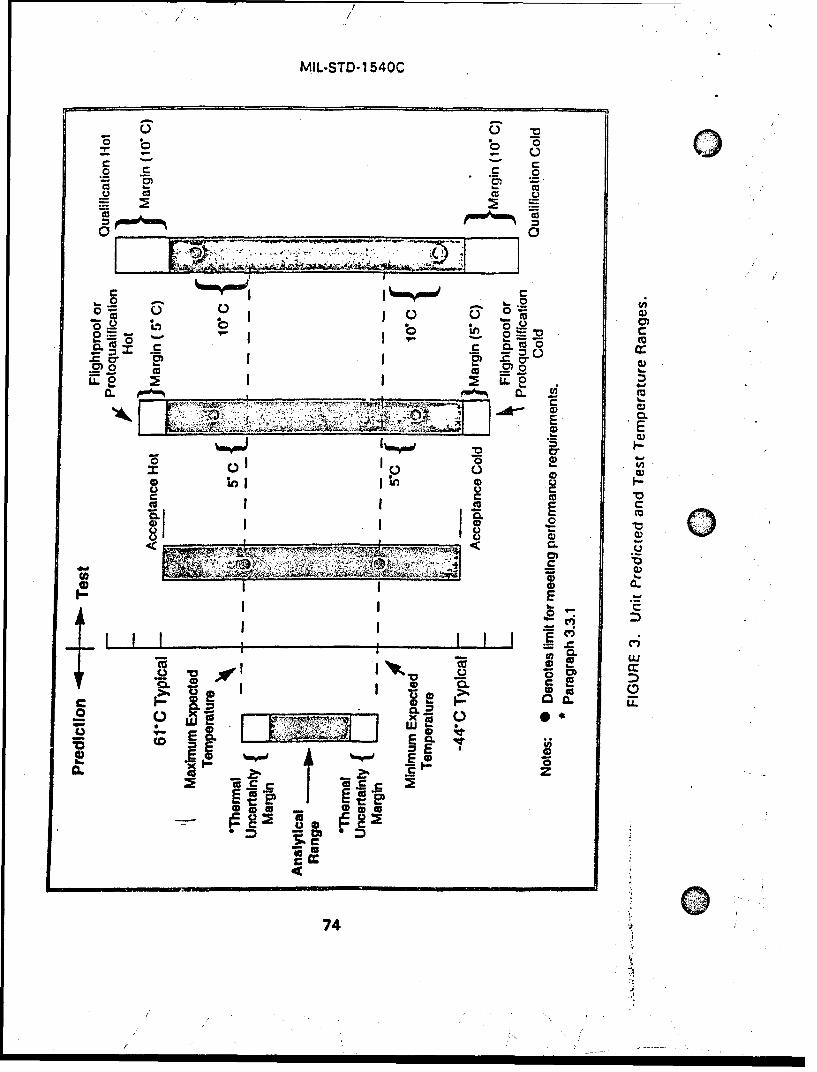
MIL-STD-1 540C
cu u
0
Lo b_ 0 n o4
CL01 0 c L)0r
B.L 0_ 0 1 L'~ I C
(DE0
1 CD
C ca
f CL Ca
CL 1!
CLCC. UJ
I 0
Ii E-L
CD x CD )
74
MIL-STD-1 540C
7.1.2 Acoustic Environment. Acceotance Tests. The acceptance testacoustic spectrum shall be the maximum expected environment (3.3.4), but notQ less than the minimum free-field spectrum in Figure 4. The minimum duration ofthe acceptance acoustic test is 1 minute.
7.1.3 Vibretion Environment. Acceotance Tests. The acceptance test randomvibration spectrum shall be the maximum expected environment (3.3.5), but notbelow the minimum spectrum in Figure 5 for a unit or below the minimumspectrum in Figure 6 for a vehicle. The minimum spectrum for a unit whose massexceeds 23 kilograms (50 pounds) should be evaluated on an individual basis. Theacceptance sinusoidal vibralion amplitude, if significant, shall be that of themaximum expected sinusoidal vibration environment (3.3.6). When concurrentrandom and sinusoidal vibration during service life (3.5.6) can be ,,lore severe thaneither considered separately, an appropriate combination of the two types ofvibration should be used for the test. The minimum duration of the acceptancerandom vibration test shall be 1 minute for each of 3 orthogonal axes.
7.1.4 Storaoe Tests: Vehicle. S•ubsvstem. or Unit Acceotance. Storage testrequirements consist of appropriate testir., after storage (such as vibration,thermal, and static load or pressure) based on the vehicle design, and the durationand conditions of storage. Items having age-sensitive material may require periodicretesting and those having rotating elements may require periodic operation.
7.2 VEHICLE ACCEPTANCE TESTS
The vehicle acceptance test baseline shall include all the required testsspecified in Table XII. The "other" tests (3.5.4) deemed applicable, and anyspecial tests for the vehicle element (such as alignments,- instrument calibrations,antenna patterns, and mass properties) shall also be conducted as part ofacceptance testing. If the vehicle is controlied by on-board data processing, theflight version of the computer software shall be resident in the vehicle computerfor these tests. The verification of the operational requirements shall bedemonstrated in these tests to the extent practicable.
7.2.1 Functignal Test. Vehicle Acceotance
7.2.1.1 Purpose. The functional test verifies that the electrical andmechan'cal performance of the vehicle meets the performance requirements of thespecifications and detects any anomalous condition.
7.2.1.2 Mechanical Functional Test. Same as the me chanical functional testfor vehicle quelification (6.2.1.2), except tests are only necessary at nominaloperational conditions.
75
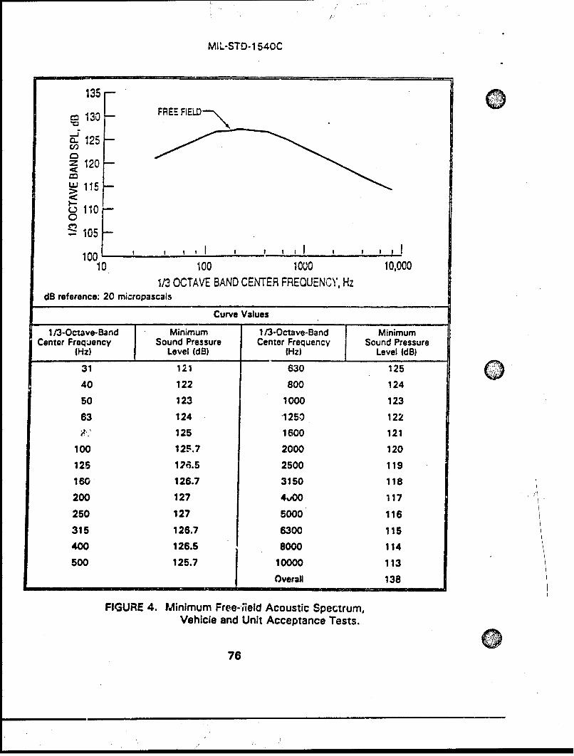
MIL-STD-1 540C
135 -
S130 -- FREE FIELD130
-125
z 120
"'115I-- S110 -oilO0
~105100 , , I , , , 1 , II.
10 100 1000 10,0001/3 OCTAVE BAND CEN'TER FREQUENCY, Hz
dB reference: 20 micropascals
Curve Values
1/3-Octave-Band Minimum 1/3-Octave-Band MinimumCenter Frequency Sound Pressure Center Frequency Sound Pressure
(Hz) Level (dB) (Hz) Level IdB)
31 121 630 125
40 122 800 124
50 123 1000 123
63 124 "1250 122
V.' 125 1600 121
100 12F.7 2000 120
125 126.5 2500 119
160 126.7 3150 118
200 127 4,00 117
250 127 5000 116
315 126.7 6300 115
400 126.5 8000 114
500 125.7 10000 113
Overall 138
FIGURE 4. Minimum Free-;ield Acoustic Spectrum,Vehicle and Unit Acceptance Tests.
76
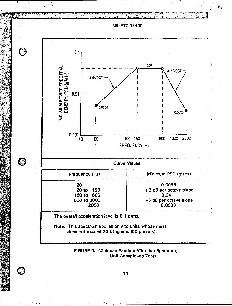
M-,'~~ ~~~ 4PM IM4A 77 - -,-ý7 v
MIL-STD-1 540CC
0.1
-- - - - -
3d8/OCTT
S0.01
0.001 I0I 00I
10 20 100 150 600 1000 2000FREQUENCY, Hz
0 Curve Values
Frequency (Hz) Minimum PSD (g2IHZ)
20 0.005320 to150+ 3 dB per octave slope
150 to 600 0.04600 to 2000 -6 dB per octave slope
2000 0.0036
The overall acceleration level is 6.1 grins.
Note: This spectrum applies only to units whose mass
does not exceed 23 kilograms (50 pounds).
FIGURE 5. Minimum Random Vibration Spectrum,Unit Acceptan~ce Tests.
0 77
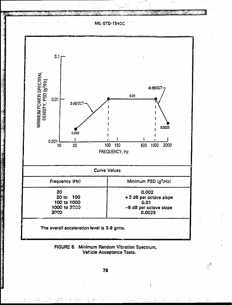
MIL-STD- 1 540C
0.1
-J
LU•-•••T
0.010 >- 3 d/C
0.0025
0.002
0.001 , I I10 20 100 150 600 1000 2000
FREQUENCY, Hz
Curve Values
Frequency (Hz) Minimum PSD (g2/Hz)
20 0.00220 to 100 + 3 dB per octave slope
100 to 1000 0.011000 to 2•C0 -6 dB per octave slope2M00 0.0025
The overa!i acceleration level is 3.8 grms.
FIGURE 6, Minimum Random Vibration Spectrum,Vehicle Acceptance Tests.
78
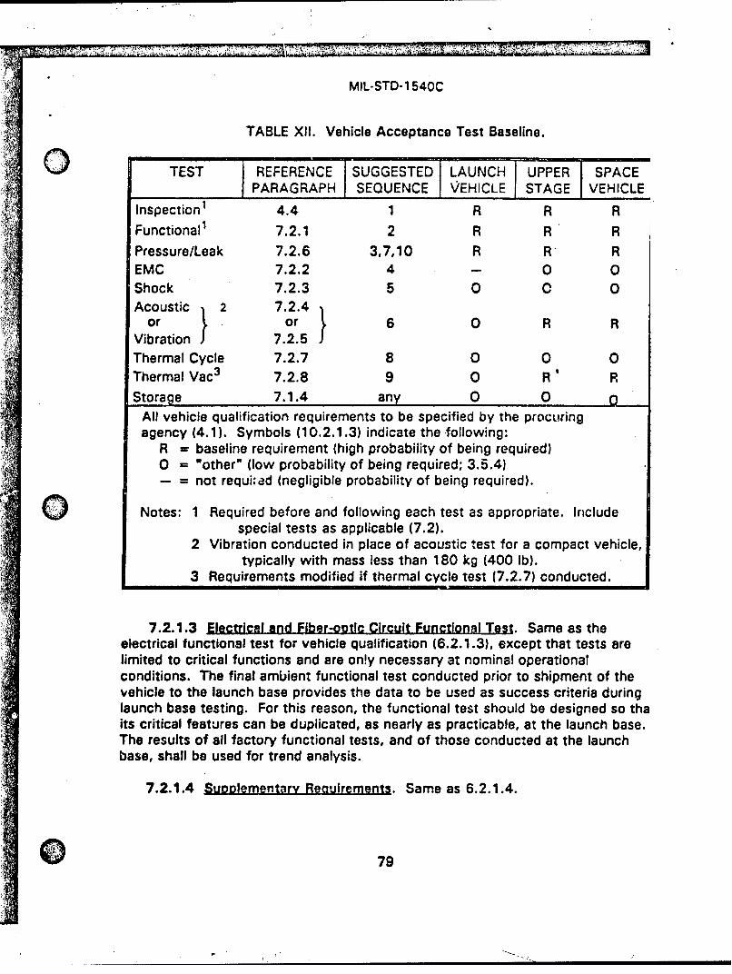
MIL-STD-1 540C
TABLE XII. Vehicle Acceptance Test Baseline.
TEST REFERENCE SUGGESTED LAUNCH UPPER SPACEPARAGRAPH SEQUENCE VEHICLE STAGE VEHICLE
Inspection1 4.4 1 R R RFunctional1 7.2.1 2 R R R
Pressure/Leak 7.2.6 3,7,10 R R REMC 7.2.2 4 - 0 0Shock 7.2.3 5 0 0 0Acoustic 2 7.2.4
or } or 6 0 R RVibration 7.2.5Thermal Cycle 7.2.7 8 0 0 0Thermal Vac 3 7.2.8 9 0 R R
Storage 7.1.4 any 0 0All vehicle qualification requirements to be specified by the procuringagency (4.1). Symbols (10.2.1.3) indicate the following:
R = baseline requirement (high probability of being required)0 = "other" (low probability of being required; 3.5.4)- = not requi;ad (negligible probability of being required).
0 Notes: 1 Required before and following each test as appropriate. Includespecial tests as applicable (7.2).
2 Vibration conducted in place of acoustic test for a compact vehicle,typically with mass less than 180 kg (400 Ib).
3 Requirements modified if thermal cycle test (7.2.7) conducted.
7.2.1.3 Electrical and Fiber-optic Circuit Functional Test. Same as theelectrical functional test for vehicle qualification (6.2.1.3), except that tests arelimited to critical functions and are on!y necessary at nominal operationalconditions. The final ambient functional test conducted prior to shipment of thevehicle to the launch base provides the data to be used as success criteria duringlaunch base testing. For this reason, the functional test should be designed so thaits critical features can be duplicated, as nearly as practicable, at the launch base.The results of all factory functional tests, and of those conducted at the launchbase, shall be used for trend analysis.
7.2.1.4 Suoolementarv Reauirements. Same as 6.2.1.4.
079
MIL-STD-1 540C
7.2.2 Electromeanetic Compatibility (EMCI Test. Vehicle Acceptance. LimitedEMC acceptance testing shall be accomplished on vehicles to chock on marginalEMC compliance indicated during vehicle qualification testing and to verify thatmajor changes have not occurred on successive production equipment. The limitedtests shall include measurements of power bus ripple and peak transients, andmonitoring of seiected critical circuit parameters.
7.2.3 Shock Test. Vehicle Acceotance
7.2.3.1 EPu.g.,Q. The shock test simulatws the dynamic shock environmentimposed on a vehicle in flight in order to detect material and workmanship defects.
7.2.3.2 Test Description. Same as 6.2.3.2, except that the dynamicinstrumentation may be reduced.
7.2.3.3 Test Activations. Shock acceptance testing of vehicles should beperformed in those instances deemed advisable due to severity of the environmentor susceptibility of the design. One activation of those events causing significantshocks to critical and shock sensitive units should be conducted. Firing of bothprimary and rodundant explosive-ordnance devices is required in the samerelationship as they are to be used in flight. However, when the structure isexplosively severed, as in the case of a shaped charge, such testing isdiscretionary. To aid in fault detection, the shock test should be conducted withsubsystems operating and monitored to the greatest extent practicable.
7.2.4 Acoustic Veh!cle Acceotnnce
7.2.4.1 EJ20s.. The acoustic test simulates the flight or minimumworkmanship-screen acoustic environment and the induced vibration on units inorder to expose material and workmanship defects that might not be detected in astatic test condition. It also serves as an acceptance test for functionalsubsystems, units, and interconnection items that have not been previouslyacceptance tested.
7.2.4.2 Ttest Description. Same as 6.2.4.2, except that the dynamicinstrumentation may be reduced.
7.2.4.3 Test Level and Duration. The acoustic anvironrnent shall be asdefined in 7.1.2. Operating time for launch operating elements should be dividedapproximately equally between redundant units. Where insufficient time isavailable to test redundant units, functions, and modes that are operating duringthe launch, ascent, or reentry phase, extended testing shall be at a level no lowerthan 6 dB below the acceptance level.
so

MIL-STD-1 540C
7.2.4.4 Supolementarv Reouirements. Same as 6.2.4.4, except only unitsthat are operating or pressurized during launch, ascent, or reentry phase need beenergized and sequenced through operational modes.
7.2.5 Vibration Test. Vehicle Acceotance
7.2.5.1 Purpose. Same as 7.2.4.1. The vibration test may be conducted inlieu of an acoustic test (7.2.4) for a compact vehicle which can be excited moreeffectively via interface vibration than by an acoustic field. Such vehicles typicallyhave a mass below 180 kilograms (400 pounds).
7.2.5.2 Test Description. Same as 6.2.5.2, except that dynamicinstrumentation may be reduced.
7.2.5.3 Test Level and Duration. The random vibration environment shall beas defined in 7.1.3. When necessary to prevent excessive input forces or unitresponses, the spectrum at the vehicle input may be limited or notched, but notbelow the minimum spectrum in Figure 6. Vibration shall be applied in each of the3 orthogonal axes as tested for qualification. Where insufficient time is availableto test redundant circuits, functions, and modes that are operating during thelaunch, ascent, or reentry phase, extended testing shall be at a level no lower than6 dB below the acceptance level.
7.2.5.4 Suooiementarv Reaulrements. Same as 6.2.5.4, except only unitsthat are operating or pressurized during the launch, ascent, or reentry phase needbe energized and sequenced through operational modes.
7.2.6 Pressure and Leakaae Tests. Vehicle Acceotance
7.2.6.1 Purmg.. The pressure and leakage test demonstrates the capabilityof fluid subsystems to meet the specified flow, pressure, and leakagerequirements.
7.2.6.2 Test Descruoion. Same as 6.2.6.2.
7.2.6.3 Test Levels nnd Dura.ions.
a. Same as 6.2.6.3a.
b. Same as 6.2.6.3b, except only 1 pressure cycle.
7.2.6.4 lernentarv Recuirrnentsl. Same as 3.2.6ý.4.
MIL-STD-1 540C
7.2.7 Thermal Cycle Test. Vehicle Acceotance
7.2.7.1 PI.Q.s. The thermal cycle test detects material, process, andworkmanship defects by subjecting the vehicle to a thermal cycle environment.
7.2.7.2 Test Descriotion. Same as 6.2.7.2.
7.2.7.3 Test Level and Duration. The minimum temperature range shall be50*C. The average rate of change of temperature from one extreme to the othershall be as rapid as practicable. Operating time should be divided approximatelyequally between redundant circuits. The minimum number of thermal cycles shallbe 4 (Tables V and VI).
7.2.7.4 Sulolementarv ReQuirements. Same as 6.2.7.4. If the thermal cycletest is implemented, only one thermal cycla is required in the thermal vacuumacceptance test specified in 7.2.8.
7.2.8 Thermal Vacuum Test. Vehicle Accentgnco
7.2.8.1 Purnose. The thermal vacuum test detects material, process, andworkmanship defects that would respond to vacuum and thermal stress conditionsand verifies thermal control.
7.2.8.2 Test Descrigtion. Same as 6.2.9.2. 47.2.8.3 Test Levels and Duration. Temperatures in various equipment areas
shall be controlled by the external test environment and ;nternal heating resultingfrom equipment operation so that the hot (or cold) temperature on at least one unitin each equipment area equals the acceptance test temperature as defined in7.1.1. For space and upper-stage vehicles, the pressure shall be maintained at orbelow 13.3 millipasnals (10"4 Torr). For launch vehicles, the pressure shall bemaintained at equal to or less than the pressure commensurate with the highestpossible service altitude.
Operating time should be divided approximately equally between redundantcircuits. The thermal vacuum acceptance test shall include at least 4 completehot-cold cycles at the maximum predicted orbital rate of temperature change andhave at least an 8-hour soak at the hot and cold temperatures during the first andlast cycles. For intermediate cycles, the soak duration at each temperatureextreme shall be 4 hours minimum. The soak duration shall be extended asnecessary to test flight operational conditions including redundancy. If thealternate thermal cycle test (7.2.7) is conducted, then only 1 hot-cold thermalvacuum cycle shall be conducted with an 8-hour minimum soak duration at hot andcold temperatures (Tables V and VI).
82
MIL-STD-1 540C
During one cycle, thermal equilibrium shall be achieved at both hot and coldtemperatures to allow collection of sufficient data to verify the funr.tion of anythermostats, louvers, heat pipes, electric heaters, and to assess the controlauthority of active thermal subsystems.
7.2.8.4 SupDlementarv Reauirements. Same as 6.2.9.4, except that theacceptance temperature limits apply. Performance within specification is notrequired at temperatures beyond the maximum and minimum expectedtemperatures.
7.3 SUBSYSTEM ACCEPTANCE TESTS
Except for pressurized subsystems, subsystem-level acceptance tests areconsidered discretionary. These tests can be effective since failures detected atthis level usually are much less costly to correct than are those detected at thevehicle level. Also, certain acceptance tests should be conducted at thesubsystem level where this level provides a more perceptive test than would bepossible at either the unit or vehicle level. The desirability of conducting thesesubsystem acceptance tests should be evaluated considering such factors as
a. The relative accessibility of the subsystem and its units.
b. The retest time at the vehicle level.
c. The cost and availability of a subsystem for testing of spare units.
When subsystem level tests are performed, the test requirements are usually basedon vehicle-level test requirements.
7.3.1 Proof Load Test. Structural Subsystem Acceotance
7.3.1.1 PurJpgo. The proof load test shall be required for all bondedstructures, and structures made of composite material or having sandwichconstruction. It detects material, process, and workmanship defects that wouldrespond to structural proof loading. The proof load test is not required if a provennondestructive evaluation method, with well established accept and reject criteria,is used.
7.3.1.2 Test Descrigtions. Same as 6.3.1.2, except that every structuralelement shall be subjected to its proof load and not to higher loading.
7.3.1.3 Test Level and Duration
a. Saic LotLgd. Unless otherwise specified, the proof load for flightitems shall be 1.1 times the limit 'oad (3.4.6).
83
//
MIL-STD-1 540C
b. Duretion. Loads shall be applied as closely as practicable to actualflight loading times, with a minimum dwell time sufficient to record,4test data.
7.3.2 Preof Pressure Test. Pressurized Subsystem AccePtance
7.3.2.1 Pu[ose. The proof pressure test detects material and workmanshipdefects that could result in failure of the pressurized subsystem.
7.3.2.2 Test Descriation. Same as 6.4.8.2a.
7.3.2.3 Test Levels and Duration. Same as 6.4.8.3b.
7.4 UNIT ACCEPTANCE TESTS
The unit acceptance test baseline consists of all the required tests specified inTable XIII. Any special tests, and the "other" tests (3.5.4) deemed applicable,shall also be conducted us part of acceptance testing.
Unit acceptance tests shall normally be accomplished entirely at the unit level.Acceptance tests of certain units (such as solar arrays, Interconnect tubing, radio-frequency circuits, and wiring harnesses) may be partially accomplished at higherlevels of assembly.
Where units fall into two or more categories of Table XIII, the required testsspecified for each category shall be applied. For example, a star sensor may beconsidered to fit both "Electrical and Electronic Equipment" and "OpticalEquipment" categories. In this example, a thermal cycle test would be conductedsince it is required for electronic equipment, even though there is no requirementfor thermal cycling of optics. Similarly, an electric motor-driven-actuator fits both"Electrical and Electrical Equipmento and "Moving Mechanical Assembly"categories. The former makes thermal cycling a required test, even though this isan "other" test (3.5.4) for the moving mechanical assembly category.
7.4.1 Functional Test. Unit Acceotance
7.4.1.1 Putnse. The functional test verifies that the electrical andmechanical performance of the unit meets the specified operational requirements ofthe unit.
7.4.1.2 Tetst Descriglon. Same as 6.4.1.2.
7.4.1.3 Supolement3rv Rsgulfament. Same as 6.4.1.3.
84
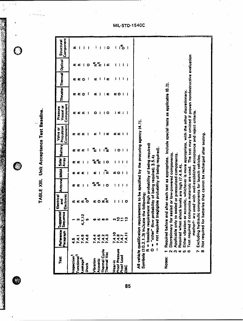
MIL-STD-1 540C
I1 lo 1 1,01
1 0 = I
.0 0
.2
CL
u 4-
-00
IO c *
0.0
cc soaqc18 P
"a .. 6 U .0 C V
0 CL
w E .-0c 1 II : -
92 IE u&r =o (U Z
C5

THIS
PAGEis
MISSING
IN
ORIGINALDOCUMENT
MIL-STD-1540C
7.4.2.4 Supolementarv Reouirements. Same as 6.4.2.4, except that units areonly required to meet their performance requirements within specification over themaximum expected temperature range.
7.4.3 Thermal Vacuumn Test, Unit Accnotanca
7.4.3.1 Purp..Q;Q. The thermal vacuum test Detects material and workmanshipdefects by subjecting the unit to a thermal vacuum environment.
7.4.3.2 Iest Description. Same as 6.4.3.2, except that the space nuclearradiation environment need not be simulated.
7A4.3.3 Test Levels and Duration
a. Pressure. The pressure shall be reduced from atmospheric to 13.3miilipascals 110-4 Torr) for on-orbit simulation, or to the functionallyappropriate reduced pressure, at a rate that simulates the ascentprofile, to the extent practic3ble. For launch vehicle units, thevacuum pressure shall be modified to reflect an altitude consistentwith the maximum service altitude. For units that are proven to befree of vacuum related failure modes, the thermal vacuum acceptancetest may be conducted at ambient pressure.
b. Temseratur. The hot and cold temperatures shall be the acceptance 4temperature limits (7.1.1).
c. D . The basic requirement, except for electrical and electronicunits, is a single cycle with 6-hour hot and cold soaks (Table VI). ForeWectrical and electronic units, a minimum of 4 thermal vLcuum cyclesshall be used (Table VI). Temperature soak duration3 shall be at least6 hours at the hot temperature and 6 hours at the ,od temperatureduring the first and last cycle. During the two i.iermedi,-te ,yc!,'s,the soaks shall be 1 hour long. During each soak period, ch, onit shallbe turned off until the temperature has stabilized and then turne, on.Measurement of temperature soak durations (3.5.10) shall betiin atthe time of unit turn-on (Figure 1).
7.4.3.4 Su1olementgry Regulrements. Functional tests shall be conducted atthe hot and cold temperatures during the first and last cycle, and after return ofthe unit to ambient temperature in vacuum. During the remainder of the test,electric&l and electronic uniks, Including all redundant circuits and paths, shall becycled through various operational modes. Perceptive parameters shall bemonitored for failures and intermittents to the maximum extent practicable. Unitsshall me3t their performance requirements over the maximum expected
887
MIL-STD-1 540C
temperature range. Units shall be operated over the entire acceptance temperatureOirange, although performance within specification is not required if the acceptancetest temperatures extend beyond the minimum or maximum expectedtemperatures.
For moving mechanical assemblies, performance parameters, such as currentdraw, resistance torque or force, actuation time, velocity or acceleration, shall bemonitored. Compatibility of thrusters with their operational fluids shall be verifiedat test temperature extremes.
7.4.4 Vibration Test. Unit Acceotance
7.4.4.1 E_==. The vibration test detects material and workmanshipdefects by subjecting the unit to a vibratir n environment.
7.4.4.2 Test Descriotlon. Same as 6.4.4.2, except that attached hydraulicand pneumatic lines are not required. Units mounted on shock or vibrationisolators shall normally be tested hard mounted to assure that the minimumspectrum shown in Figure 5 is input to the test item.
7.4.4.3 Tost LeveLand Duration. The vibration environment shall be asdefined in 7.1.3. The minimum spectrum is shown in Figure 5. Where insufficienttime is available to test all modes of operation, extended testing at a level no lowerthan 6 dB below the acceptance test level shall be conducted as necessary tocomplete functional testing.
7.4.4.4 Suoplementarv Reoulrements. Same as 6.4.4.4 and if the dynamictest configuration (unit and fixture) changes from the qualification configuration,then the fixture evaluation (6.4.4.5) shall be repeated before testing to acceptancelevels.
7.4.4.5 Soeclal Considerations for Isolators. All isolators shall be lot tested inat least one axis, with rated supported mass, to verify that dynamic amplificationand resonant frequency are within allowable limits. Test inputs may either be themaximum expected random vibration level applied for at least 15 seconds, or be areference sinuso!dal input having a frequency sweep rate not greater than 1 octaveper minute.
7.4.5 Acoustic Test. Unit Acceptance
7.4.5.1 Pur.os.. The acoustic test detects material and workmanshipdefects by subjecting the unit to an acoustic environment.
7.4.5.2 Test Deicrintlon. Same as 6.4.5.2.
88
II
MIL-STD-1 540C
7.4.5.3 Test Level and Duration. The unit acoustic environment shall be asdefined in 7.1.2. Where insufficient time is available during the 1-minute to checkredundant circuits, functions, and modes that are operating during the launch,ascent, or reentry phase, extended testing at a level no lower than 6 dB below theacceptance level shall be conducted as necessary to complete functional testing.
7.4.5.4 Surpnlementerv Reauirements. Same as 6.2.4.4.
7.4.6 Shock Test. Unit ACceptance
7.4.6.1 Plr~s.. The shock test is intended to reveal material andworkmanship defects in units subject to high-level shock environments in flight.
7.4.6.2 Test Descriotion. The unit shall be attached at its normal points tothe same fixture or structure used for its shock qualification test (6.4.6.2). Theunit shall be electrically energized and monitored. The test technique employedshall be identical to that selected for its qualification, differing only in level and thenumber of repetitions. A functional test of the unit shall be performed before andafter the shock test. The unit shall be electrically energized during the testing.Circuits should be monitored for intermittents to the maximum extent practicable.
7.4.6.3 Tesl, Level and Exposure. The shock response spectrum in bothdirections of each of 3 orthogonal axes shall be at !east the maximum expectedlevel for that direction. A sufficient number of shocks sh311 be imposed to meet C]the required level in each of these 6 directions at least once.
7.4.6.4 Suoolementarv Reaul-ements. A shock acceptance test becomes arequired test (3.5.4) if the maximum expected shock response spectrum in g'sexceeds 1.6 times the frequency in Hz (corresponding to a velocity of 2.54meters/second or 100 inches/second). For example, if the maximum expectedshock response spectrum value at 2000 Hz exceeds 3200g, the test is required.
7.4.7 Proof Load Test. Structurel Unit Acceotonce
7.4.7.1 Eurpogs. The proof load test shall be conducted for all structuralunits made from composite material or having adhesively bonded parts. The proofload test detects material, process, arnd workmanship defects that would respondto structural proof loading. The requirement for the proof load test Is waived if aproven nondestructih'e evaluation method, with well established accept and rejectcriteria, is used inste d.
7.4.7.2 Test Descriptions. Same as 7.3.1.2.
7.4.7.3 Test Level and Duration. Same as 7.3.1.3.
89

THIS
PAGEis
MISSING
IN
ORIGINAL
DOCUMENT
962
MIL-STD-1540C
7.4.10.3 Test Levels and Duration.
0 a. Pressure. Ambient pressure should normally be used.
b. TemperatiJre. Ambient temperature shall be used for operations if thetest objectives can be met. Otherwise, temperatures representative ofthe operational environment shall be used.
c. Duation. The number of cycles shall be either 15 or 5 percent of thetotal number of expected cycles during service life (3.5.6), whicheveris greater.
7.4.10.4 Supplementary Requirements. Perceptive parameters shall bemonitored during the wear-in test tr. detect evidence of degradetion.
7.4.11 EMC Test. Unit Acceptance. Limited EMC acceptance testing shall beaccomplished on units that exhibit emission or susceptibility characteristics, whichmay adversely affect vehicle performance, to verify that these characteristics havenot deterioratod from the qualification test levels. The tests should be restricted toonly those necessary to evaluate these critical characteristics.
91
MIL-STD-1 540C
SECTION 8
ALTERNATIVE STRATE( iES
The qualification testing in Section 6 proviJes a demonstration that the design,manufacturing, and acceptance testing produces flight items t.hat meetspecification requirements. In a minimum-risk program, the hardware itemssubjected to qualification tests are themselves not eligible for flight, since there hasbeen no demonstration of remaining life from fatigue and wear standpoints. Yet,programmatic realities of limited production, tight schedules, and budgetary. limitsdo not always provide for dedicated nonflight qualification items. In response,strategies have evolved to minimize the risk engendered by this situation. Thethree strategies or combinations thereof, described in this section, may be used atthe vehicle, subsystem, and unit levels. It should be recognized that thesestrategies present a higher risk than the use of standard acceptance tested itemsfor flight that have margins demonstrated by testing of a dedicated qualificationitem. The higher risk of these alternate strategies may be partially mitigated byenh3nced development testing and by increasing the design factors of safety.
The strategies are intendcd for use in space vehicle programs that have a very
limited number of vehicles.
8.1 SPARES STRATEGY
This strategy does not alter the qualification and acceptance test requirementspresented in Section;:: 6 and 7. Yet, in some cases, qualification hardware may beused for flight if the risk is minimized. In a typical case, the qualification testprogram results in a qualification test vehicle that was built using units that hadbeen qualification tested at the unit level. After completing the qualification tests,the critical units can be removed from the vehicle and the qualification vehicle canthen be refurbished, as neceasary. Usually a new set of critical units would beinstalled that had only been acceptance tested. This refurbished qualificationvehicle would then be certified for flight when it satisfactorily completes thevehicle acceptance tests in 7.2. In vehicles where redundant units are provided,only one of the redundant units would have been qualification tested at the unitlevel, so only it would be removed and replaced. The qualification units that weieremoved would be refurbished, as necessary, and would typically be used as flightspares. However, qualification units that are mission or safety critical (3.2;2)should never bb used for flight.
92
.", -"- : i " .•": "•:~ ~~-•s:- • .' : "' """ "•
MIL-STD-1 540C
8.2 FLIGHTPROOF STRATEGY
With a flightproof strategy, all flight items are subjected to enhancedacceptance testing, and there is no qualification item. The risk taken is thathas been no formal demonstration of remaining life for the flight items. Thisalleviated to some degree by the fact that each flight item has met requiremiunder acceptance testing at higher than normal levels. The test levels are rmless than those specified in Section 6 for qualification, but are never less thathose specified in Section 7 for acceptance. The test durations for the flighttest strategy are the same as those specified for acceptance. It is recommerthat development testing be used to gain confidence that adequate margin,especially in a fatigue or wear sense, remains after the maximum allowedaccumulated acceptance testing at the enhanced levels.
8.2.1 Vehicle FlightDroof Tests. The vehicle flightproof tests shall beconducted as in 7.2 (Table XII), with the following modifications:
a. The vehicle shock test shall be conducted as in 6.2.3 for the firflight vehicle. For subsequent vehicles, only 1 activation of sigievents is required (7.2.3).
b. The vehicle acoustic and random vibration tests shall be condu(in 7.2.4 and 7.2.5. except that the test level shall be 3 dB abokacceptance test environment (7.1.2 and 7.1.3). For -he first fliivehicle, the tests shall be conducted with power on, to the extfpracticable.
c. The vehicle thermal vacuum tests shall be conducted as in 7.2.,except that !he hot and cold temperatures shall be 50C beyondacceptance temperatures for units (7.1.1).
d. The vehicle thermal balance test shall be conducted on the firstvehicle as in 6.2.8.
e. If a thermal cycle test is conducted as in 7.2.7. then the minimvvehicle temperature range shall be f'OTC.
f. EMC tests shall be conducted as in 6.2.2 for the first flight vehFor subsequent vehicles, the EMC test of 7.2.2 shall be require
g. The r iodel survey shall be conducted as in 6.2.10 on the first fvehicle.
93
MIL-STD-1 540C
8.2.2 Subuystem Flizhtoroof Tests. The subsystem flightproof tests shall beconducted ss in 7.3. In addition, a proof load test shall be conducted on allstructures in the structural subsystem. The proof load shall be equal to 1.1 timesthe limit load.
8.2.3 UnIt Frightoroof Tests. The unit flightproof tests shall be conducted asin 7.4 (Table XIII), with the following modifications:
a. For the first flight unit only, the shock test shall be conducted as in6.4.6. except that the shock level shall be 3 dB above the acceptancetest level, achieved once in both directions of 3 axes. For subsequentunits, the shock test shall be conducted if required as described in7.4.6. except that the shock test level shall be 3 dB above theacceptance test level.
b. Vibration and acoustic tests shall be conducted as in 7.4.4 and 7.4.5,except that the test level shall be 3 dB greater than the acceptancetest level (7.1.2 and 7.1.3).
c. The unit thermal vacuum tests shall be conducted as in 7.4.3, exceptthat the hot and cold temptaturos shall be SC beyond theacceptance test temperature, ,7.1.1). For the first flight antenna andsolar array units, this thermal vacuum test shall be required.
d. The unit thermal cycle tests shall be conducted as in 7.4.2, exceptthat the hot and cold temperatures shall be 50C beyond theacceptance test temperatures (7.1.1).
e. The unit EMC test shahl be conducted on the first unit as in 6.4.11.
The unit flightproof test approach shall not be allowed for pressure vessels,pressure components, structural components with a low fatigue margin, andnonrachargeable batteries. These units shall follow k normal qualification andacceptance program as specified in Sections 6 and 7.
8.3 PIROTOQU.ALLCAE1OQ rRAI"GY
With a protoqualificatlon strategy, a modified qualification (protoqualification)is conducted on a singlo item end that test Item is considered to be available forflight. The normal acceptance program In Section 7 Is then conducted on all otherflight ihems.
94
MIL-STD-1540C
8.3.1 VehIcle Protoput-,ificatlon Tests. The protoqualification tests shall bO conducted as in 6.2 (Table Vill), with the following modifications:
a. The shock test shall be conducted as in 6.2.3, except that only 2repetitions of activated events are required.
b. The acoustic or random vibration tests shall be conducted as in 6.;and 6.2.5, except that the duration factors shall L~e 2 (instead of 4and the level margin for the flight environment shall be 3 dO (inste,of 6 dB typically) in place of ttie requirements in 6.1 .4. if the testaccelerated (6.1.4.2), the time reduction factor shall be based on Ireduced level margin per Table VII.
c. The thermal vacuum test shall be conducted as in 6.2.9, except ttthe hot and cold temperatures shall be 50C beyond the acceptancitemperatures for units (7.1.1) and the number of cycles shall be htof those in Table VI.
d. If the alternate thermal cycle test ;s conducted as in 6.2.7. then ttminimum vehicle temperature range shall be 60 0C and the numbercycles shall be half of those in Table VI.
8.3.2 Subsvytem Protoaulalflcatlon TaefA. The subsystem protoqualifica'tests shall be conducted as in 8.3.1. except that the structural subsystem testsshall be conducted as in 6.3 (Table IX) with an ultimate load test factor of 1.2!No detrimental deformation shall be allowed during the test. In addition, thedesign safety factor for ultimate shall be 1.4 and the design safety factor for yishall be 1.25.
8.3.3 Unit Protogual1fugation Tests. The protoqualification unit tests shallconducted as In 6.4 (Table X), with the following modifications:
a. The shock test shall be conducted as in 6.4.6, except that only 2repetitions and only a 3 dB level margin for the flight environment(hnstead of 6 dB typically, Table IV' shall be required.
b. The random vibration or acoustic tests shall be conducted as in 6.'and 6.4.5, except that the duration factors shall be 2 (instead of 4and the level margin for the flight environment shall be 3 dB (inste;of 6 dB typically). If the test is accelerated (6.1.4.2), the timereduction factor shall be based on the reduced level margin per TalVII.
95
MIL-STD- 1540C
c. The thermal vacuum tests shall be conducted as in 6.4.3, except thatthe hot and cold temperatures shall be 5VC beyond the acceptancetemperatures for units (7.1.1) and the number of cycles shall be halfof those in Table VI.
d. The thermal cycle tests shall be conducted as in 6.4.2, except thatthe hot and cold temperatures shall be 5°C beyond the acceptancetemperatures fcr units (7.1.1) and the number of cycles shall be halfof those in Table VI.
8.4 CQOMBINATION TEST STRATEGIES
Various comnbinations of strategy may be considered depending on specificprogram considerations and the degree of risk deemed acceptable. For example,the protoqualification strategy for units (8.3.3) may be combined with theflightproof strategy for the vehicle (8.2.1). In other cases, the flightproof strategywould be applied to some units (8.2.3) peculiar to a single mission, while theprotoqualification strategy may be applied to multi-mission units (8.3.3). In suchcases, the provisions of each method would apply and the resultant risk would beincresseC ,-artespondingly.
• 96
MIL-STD-1 540C
SECTION 9
PRELAUNCH VALIDATION AND OPERATIONAL TESTS
9.1 PRELAUNCH VALIDATION TESTS. GENERAL REQUIREMENT
Prelaunch validation testing is accomplished at the factory and at the launbase, with the objective of demonstrating launch system and on-orbit systemreadiness. Prelaunch validation testing is usually divided into two phases:
Phase a. Integrated system tests (Step 3 tests, MIL-STD-1833).
Phase b. Initial operational tests and evaluations (Step 4 tests,MIL-STD- 1833).
During Phase a, the test series establishes the vehicle baseline data in thefactory preshipment acceptance tests. All factory test acceptance data shou;accompany delivered flight hardware. When the launch vehicle(s), upper-stagvehicle(s), and space vehicle(s) are first delivered to the launch site, tests shaýconducted as required to assure vehicle readiness for integration with the othlvehicles. These tests also verify that no changes have occurred in vehicleparameters as a result of handling and transportation to the launch btse. Thelaunch vehicle(s), upper-stage vehicle(s), and space vehicle(s) may each bedelivered as a complete vehicle or they may be delivered as separate stages aifirst assembled at the launch site as a complete launch system. The prelaunclvalidation tests are unique for each program in the extent of the operationsnecessary to ensure that all interfaces are properly tested. For programs thata complete vehicle to the launch site, those tests primarily confirm vehicleperformance, check for transportation damage, and demonstrate interfacecompatibility.
During Phase b, Initial operational tests and evaluations (Step 4 tests) areconducted following the Integrated system tests to demonstrate successfulintegration of the vehicles with the launch facility, and that compatibility existibetween the vehicle hardware, ground equipment, computer software, and witthe entire launch system and on-orbit system. The point at wnich the integratsystem tests end and the Initial operational tests and evaluations begin issomewhat arbitrary since the tests may be scheduled to overlap In time. To ttgreatest extent practicable, the initial operational tests and evaluations are toexercise all vehicles and subsystems through every operational mode In ordor 1ensure that all mission requirements are satisfied. These Step 4 tests shall beconducted In an operational environment, with the equipment in Its operational
S >97
MIL-STD-1 540C
configuration, by the operating personnel in order to test and evaluate theeffectiveness and suitability of the hardware and software. These tests shouldemphasize reliability, contingency pl3ns, maintainability, supportability, andlogistics. These tests should assure compatibility with scheduled range operationsincluding range instrumentation.
9.2 PRELAUN'CH VALIDATION TEST FLOW
Step 4 testing (MIL-STD-1833) of new or modified ground facilities, groundequipment, or software should be completed prior to starting the prelaunchvalidation testing of the vehicles at the launch bass. The prelaunch validation testflow shall follow a progressive growth pattern to ensure proper operation of eachvehicle element prior to progressing to a higher level of assembly and test. Ingeneral, tests should follow the launch base buildup cycle. As successive vehiclesor subsystems are verified, assembly proceeds to the next level of assembly.Following testing of the vehicles and their interfaces, the vehicles are electricallyand mechanically mated and integrated into. the launch system. Upper-stagevehicles and space vehicles employing a recoverable flight vehicle shall utilize aflight vehicle simulator to perform mechanical and electrical interface tests prior tointegration with the flight vehicle. Following integration of the launch vehicle(s),upper-stage vehicle(s), and space vehicle(s), functional tests of each of thevehicles shall be conducted to eaisure its proper ope:ation following the handlingoperations involved in mating. Vehicle cleanliness shall be monitored by use ofwitness plates. In general, the Step 4 testing of the launch system is conductedfirst, then the Step 4 testing of the on-orbit space system is conducted.
9.3 PRELAUNCH VALIDATION TEST CONFIGURATION
During each test, the applicable vehicle(s) should be in their flight configurationto the maximum extent practicable, consistent with safety, control, and monitoringrequirements. For programs utilizing a recoverable flight vehicle, the testconfiguration shall Include any airborne support equipment required for the launch,ascent, and space vehicle deployment phases. This equipment shall bemechnnically and electrically mated to the space vehicle in Its launch configuration.Whenever practicable, ground support equipment should have a floating-point-ground scheme that is connected to the flight vehicle single-point ground. Isolationresistance tests shall be run to verify the correct grounding scheme prior toconnection to the flight vehicle. This reduces the possibility of ground equipmentinterference with vehicle performance. All ground equipment shall be validatedprior to being connected to any flight hardware, to preclude the possibility of faultyground equipment causing damage to the flight hardware or inducing ambiguous orInvalid data. Test provisions shall be made to verify Integrity of circuits into whichflight jumpers, arm plugs, or enable plugs have been inserted.
98
MIL-STD-1 540C
9.4 PRELAUNCH VALIDATION TEST DESCRIPTIONS
The prelaunch validation tests shall exercise and demonstrate satisfactoryoperation of each of the vehicles through all of theic mission phases, to themaximum extent practicable. Test data shall be compared to corresponding daobtained in factory tests to identify trends in performance parameters. Each teprocedure used shall include test limits and success criteria sufficient to permitrapid determination as to whether or not processing and integration of the launisystem should continue. However, the final acceptance or rejection decision, i:most tests, depends upon the results of post-test data analysis.
9.4.1 Functional Tests. Electrical functional tests shall be conducted thatduplicate, as nearly as practicable, the factory functional tests performed forvehicle acceptance. Mechanical tests for leakage, valve and mechanismoperability, and fairing clearance shall be conducted.
9.4.1.1 Simuilators. Simulation devices shall be carefully controlled and slbe permitted onif when there is no feasible alternative for conducting the test.When it Is necessary to employ simulators in the conduct of prelaunch validatictests, the interfaces disconnected in tOe subsequent replacement of the simuls.with flight hardware shall be revalidated. Simulators shall be used for thevalidation of ground support equipment prior to connecting it to flight hardwarr
9.4.1.2 Exploslve-ordnance Firing Circult3. If not performed at an earlierIin the factory test cycle, validation that proper Ignition energy levels are preseneach electra-explosive device (EED) shall be performed prior to final connectionthe firing circuit to the EEDs. A simulation of the EED characteristics snail be uduring these tests. The circuits shall be commanded through power-on, arm, atfire cycles. The circuits are to be monitored during the tests to detect energydensities exceeding ignition threshold during powtr-on and arm cycless, and tovalidate that proper ignition energy density Is transmitted to the conducting pintthe EED at the fire command. Circuit continuity and stray energy checks shall Imade prior to connection of a firing circuit to ordnance devices and this check ibe repeated whenever that connection is opened and prior to reconnection.
9.4.1.3 Transoartatlon and Handling Monfltorin. Monitoring for shock anivibration should be performed at a minimum of the forward and aft Interfacesbetween the shipping container transporter and the article being shipped, andthe top of the article. Maas irements should be on the article side of the interfsIn all three axes at each location. The monitoring requires a sensing and recordsubsystem capable of providing complete time histories of the most severe eveias well as condensed summaries of the events, including their time of occurronfA frequency resonse up to 300 Hz Is required. Monitoring should cover the orshipment period and the data evaluated as part of the receiving process. Expos
99.
MIL-STD-1 540C
to shock or vibration having a spectrum above the acceptance spectrum mayrequire additional testing or analysis.
9.4.2 Propulsion Subsystem Leakage ynd Functior'! Tests. Functional testsof the vehicle propulsion subsystem(s) shall be conducted to verify the properoperation of all units, to the maximum extent practicable. Propulsion subsystemleakage rates shall be verified to be within allowable limits.
9.4.3 Luaunch-criticel Ground Suonort Eouloment Tests. Hardware associatedwith ground subsystems that are flight critical and nonredundant (such asumbilicals) shall have been subjected to appropriate functional tests undersimulated functional and environmental conditions of launch. These tests shallinclude an evaluation of radio-frequency (rf) interference between systemelements, electrical power Interfaces, and the command and control subsystems.On a new vehicle design or a significant design change to the telemetry, tracking,or receiving subsystem of an existing vehicle, a test shall be run on the first vehicleto ensure nominal operation and that explosive-ordnance devices do not fire whenthe vehicle Is subjected to the worst-case electromagnetic interferenceenvironment.
9.4.4 ComoatIblIlty Test. On-orbit System.
9.4.4.1 Eu=Owg.. The compatibility test validates the compatibility of theupper-stage vehicle, the space vehicle, the on-orbit command and control network,and other elements of the space system. For the purpose of establishing thecompatibility testing baseline, It is assumed that the on-orbit command and controlnetwork is (or operationally Interfaces with) the Air Force Satellite Control Network(AFSCN). The compatibility test demonstrates the ability of the upper-stagevehicle and space vehicle, when in orbit, to properly respond to the AFSCNhardware, software, and operations team as specified in the AFSCN ProgramSupport Plan. For programs that have a dedicated ground station, compatibilitytests shall also be performed with the dedicated ground station.
9.4.4.2 Jot MsaIU;g.om. Facilities to perform on-orbit system compatibilitytests exist at the Western Range (WR) and the Eastern Range (ER). At bothlocations, thore are facilities that can command the launch, upper-stage, and spacevehicles, process telaremtry from the vehicles, as well as perform tracking andranging, thus verifying the system compatibility, the command software, thetelemetry processing software, and the telemetry modes. The required testsinclude the following:
a. Verification of the compatibility of the radio frequencies and signalwaveforms used by the flight unt's command, telemetry, and trackingIlnks.
100
/ /
MIL-STD-1 540C
b. Verification of the ability of the flight units to accept commands frory0 the command and control network(s).
c. Verificaton of the command and control networkis) capability toreceive, process, dizvlay, and record the vehicle(s) telemetry link(s)required to monitor tie flight units during launch, ascent, and on-orb'mission phases.
d. Verification of the ability of the flight units to support on-orbit trackiras required for launch, ascent, and on-orbit mission phases.
9.4.4.3 Suonlemgntary Reugm . The compatibility test should be run;soon as feasible after the vehicles arrives at the launch base. The test is madewith every vehicle to verify system interface compatibility. The test shall be runusing the software model versions that are integrated into the operational on-orbilsoftware of the vehicle under test. A preliminary compatibility test may be runprior to the arrival of the vehicle at the launch base by the use of prototypesubsystems, units, or simulators as required to prove the interface. Preliminarycompatibility tests may be run using preliminary software. Normally, a preliminarcompatibility test is run once for each series of vehicles to check designcompatibility, and is conducted well in advance of the first launch to permit oroeicorrection of hardware, software, and procedures as required. Changes in theinterface from those tested in the preliminary test shall be checked by the0 compatibility tests conducted just prior to launch. Following the completion of ttcompatibility test, the on-orbit commtnd and control network configuration ofsoftware, hardware, and procedures should be frozen until the snace vehicle is inorbit and initialized.
9.5 FOLLOW-ON OPERATIONAL TESTS
9.5.1 Follow-an Ogorational Tests and Evaluations. Follow-on OperationalTests and Evaluations shall be conducted at the launch site in an operationalenvironment, with the equipment in its operational configuratio.. The assignedoperating personnel shall identify operational system deficiencies. (Step 5 in MIL.STD- 1833).
9.5.2 nk-orbit Teltig. On-orbit testing should be conducted to verify thefunctional integrity of the space vehicle following launch and orbital maneuvering,Other on-orbit testing requirements are an important consideration in the design cany space vehicle. For example, there may be a reed to calibrate on-lineequipment or to verify the operational status of of -line equipment while in orbit.However, on-orbit testing is dependent on the built-in design features, and iftesting provisions were not provided, the desired tests cannot be accomplished.
Tol
MIL-STD-1 540C
On-orbit tests are, therefore, so program peculiar that specific requirements are notaddressed i n this Standard.
9.5.3 Tests of Reu;&bl Flight Hardware. Tests of reusable flight hardwareshall be conducted as required to achieve a successful space mission. Reusablehardware consists of the v'ahicles and units intended for repeated missions.Airborne support equipment, that performs its mission while attached to arecoverable launch vehicle, is an example of a candidate for reuse. The reusableequipment would be subjected to repeated exposure to test, launch, flight, andrecovery environments throughout its service life. The accumulated exposure timeof equi.pment retained in a recoverable vehicle and of airborne support equipment isa function of the planned number of missions involving this equipment and theretest requirements between missions. The environmental exposure time ofairborne support equipment is further dependent on whether or not its use isrequired during the acceptance testing of other nonrecoverable flight equipment.In any case, the service life of reusable hardware should include all planned reusesand all planned retesting between uses.
The testing requirements for reusable space hardware after the completion of amission and prior to its reuse on a subsequent mission depends heavily upon thedesign of the reusable item and the allowable program risk. For those reasons,specific details are not presented in this Standard. Similarly, orbiting spacevehicles that have completed their useful life spans may be retrieved by means of arecoverable flight vehicle, refurbished, and reu~sed. Based on present approaches,it is expected that the retrieved space vehicle would be returned to thecontractor's factory for disassembly, physical inspection, and refurbishment. Alloriginally specified acceptance tests should be conducted before reuse.
102
MIL-STD-1 540C
SECTION 10
0 NOTES
This Notes section is not a mandatory part of this Standard. The contents ofthis section are intended for use by government acquisition personnel for guidanceand information only.
10.1 INTENDED,
This Standard is intended for reference in applicable program specifications orin other documents, to establish general test requirements for launch, upper-stageand space vehicles; and for their subsystems and units (components). Theapplication of these test requirements to a particular program is intended to assurta high level of confidence in achieving a successful space mission. This Standardis not intended to be used in the acquisition of space system ground equipmentand associated computer software, whose test requirements are outlined inMIL-STD-1833, "Test Requirements for Ground Equipment and AssociatedComputer Software Supporting Space Vehicles' and not included in this documenDOD-STD-2167, "Defense System Software Development' and DOD-STD-2168,"Defense System Software Quality Program," also address computer software.Test requirements for space parts and materials are in their detailed specifications0 and not In this document.
10.2 TAILORED APPLICATION.
The technical requirements in each contract should be tailored to the needs olthat particular acquisition. Only the minimum requirements needed to provide thebasis for achieving the program requirements should be imposed. The cost ofimposing each requirement of this Standard should be evaluated against thebenefits. However, the risks and potential costs of not imposing requirementsmust also be considered.
Tail!oring is a continuing process throughout the acquisition that should beimplemented by the wording used to state the testing requirements.MIL-HDBK-340, "Application Guidelines for MIL-STD-1 540," is a companiondocument to this Standard that is Intended to provide helpful guidance informatiorfor tailoring.
10.2.1 Tailoring In the Specificatlons. The Standard is organized to provideself-tailoring of the requirements to various applications when referenced in thespecifications. These features include an organization of requirements by testcategories, by Item categories, by required/otherlnot-required categories, byweighting factors, and by alternative test strategies. The tailo-ing desired should
103
MII -STD-1540C
be implemented ; ie wording used to state the testing requirements in thespecifications or ler applicable contractual documents.
10.2.1.1 Test Catenories. The major test categories in this Standard are:
a. Development tests (Seciion 5).
b. Qualification tests (Section 6).
c. Acceptance tests (Section 7).
d. Flightproof and protoqualification tests (Section 8).e. Prelaunch validation tests (Section 9).
f. Operational tests (Section 9).
The general requirements stated in Section 4 apply for all of the test categories.
10.2.1.2 Item Categories. Space systems are composed of items in, variouscategories including ground equipment, computer software, procedures, personnel,as well as flight equipment. All items are tested to some degree to assuresuccessful space missions. The major item categories covered by the testingrequirements in this Standard are:
a. Vehicles (launch, upper-stage and space vehicles; Tables VII and XII).
b. Subsystems (Tab;e IX and 6.3).
c. Units (Tables X and XIII).
d. Integrated vehicles (flight vehicle, flight system, and on-orbit system).
10.2.1.3 "Requlred". "Othera. and "Not-reautred" Test2. "Required', 'other",and "not-requirede tests for each vehicle category are indicated by an ORO, 000,and "-', respectively, in Tables VIII, IX, X, XII, and XIII. The following basis hasbeen used:
a. "Required" tests are the baseline tests that are required by thisStandard because they are generally effective.
b. 0Other" tests (3.5.4) are those that are usually ineffective and have alow probability of being required. Such tests must be evaluated on acae-by-case basis. If the evaluation shows than an "other" test iseffective, it becomes a "required" test for that case.
c. *Not-required" tests are generally ineffective and are not required bythis Standard.
Unless modified by contract, the contractual compliance requirements include all ofthe "required" tests plus all "other" tests evaluated as required.
104
MIL-STD-1540C
10.2.1.4 Weightlng Factors. Even for the required tests, not all of threquirements have an equal importance or equal weight. To avoid overataltesting requirements, and hence avoid excessive costs, or numerous waivevarious categories of weighting factors are associated with the requiremenprimary weighti.ng factors that are incorporated in the Standard are:
a. Weighting factor "a". "Shall" designates the most importantweighting level, the mandatory requirements. Unless modifieacontract, the "shalt requirements constitute the firm contraclcompliance requirements. Any deviations require the approvacontracting officer.
b. Weighting factor "b". "Shall, where practicable" designatesrequirements or practices at the second highest weighting levAhternative requirements or practices may be used for specificapplications, when the use of the alternative is substantiateddocumented technical trade studies. These trade studies shomade available for review when requested, or provided to thegovernment in accordance with the contract provisions. Unlerequired by other contract provisions, noncompliance with thiwhere practicable" requirements does not require approval ofcontracting officer.
c. Weiohtina factor "ca. "Should" designates the third weightirUnless required by other contract provisions, noncompliancethese "should" requirements does not require documented tecsubstantiation, and does not require approval of the contractiiofficer.
d. Weiohtina f3ctor W". "May" designates the lowest weightintIn some cases, these "may" requirements are stated as examacceptable practices. Unl6ss required by other contract provinoncompliance with the Omay" requirements does not requireof the contracting officer and does not require documented tesubstantiation.
10.2.1.5 Alternative Test Strateig.le. The application of the alternati'strategies outlined in Section 8 should be based on life-cycle cost considetthat include the number of units being manufactured, the potentiai launchcosts of a prelaunch failure, the potential cost of the loss of mission capatto a failure, and other life-cycle costs. The fact ihat an alternative test strmay have lower testing costs does not mean it provides the lowest life-cy(Any constraints on the use of the alternative 4et strategies must be stateocontract.
105
MIL-STD-1540C
10.2.2 Teiloring in the Statement of Work (SOW).
10.2.2.1 TailorIng Summary. To make the requirements clear for a particularcontract, and to assist in the tailoring process, the procuring agency may provide asummary of tailoring requirements. To accomplish this, the procuring agencyshould complete either Table XIV or Table XV, or an adaption thereof, and includeone or the other in the contract, usually as a statement of work (SOW) task. TableXIV can be used when primarily broad, genera' i'ailoring of the requirements isdesired, with only a few specific test or test items to be specially treateddifferently. Table XV can be used when detailed tailoring of the requirements isdesired. These tables provide a recommended format for stating changes to thestringency or applicability of the baseline requirements appearing in the Standard,relating to the use of "shall" versus "should" and to "required" versus "other"(3.5.4). The latter pair appear in tables stating the applicability of various tests tocategories of vehicles, subsystems, and units. The implication of these terms isdiscussed in 10.2.1.3 and 10.2.1.4. For example, the "fully applicable" degreemay be used to allow the procuring agency to impose the highest level ofstringency for some requirements without being constrained by the baselinerequirements of this Standard. A sample of a completed Table XIV and XVappears in Tables XVI and XVII, respectively. Suggested wording for the SOW isas follows:
"XX.XXX Tailoring of MIL-STD-1 540C. Preliminary tailoring of MIL-STD-1540C is provided in the attached Requirements Applicability Matrix. Thecontractor shall review these tailored requirements and provide additionalrecommended tailoring and supporting rationale for approval by thecontracting officer."
10.2.2.2 ITst Plans. Depending on the particular acquisition phass, it may bedifficult for the procuring agency to identify which "required" and "other" tests aremost effective for a particular subsystem or test article. In these cases, theprocuring agency may request that the contractor review the "required" and"other" tests and propose an effective test plan, subject to approval by theprocuring agency. Suggested wordings for the Statement of Work is as follows:
"xx.xxx Review of Test Plans. Test plans and test procedures shall beprepared based upon the test requirements stated in the programspecifications and the guidance provided in MIL-STD-1540. Technicalreview meetings shall be conducted to present to the procuring agency therecommended test plans and procedures applicable to each item category.These presentations shall include the evaluation of the "required, otherand not-required" tests that form the basis of the test plans.
If the procuring agency wishes to formally review the applicable test plans orprocedures prepared by contractors, requirements for their preparation should bestated in the Contract Data Requirements List (CDRL; 10.5).
106
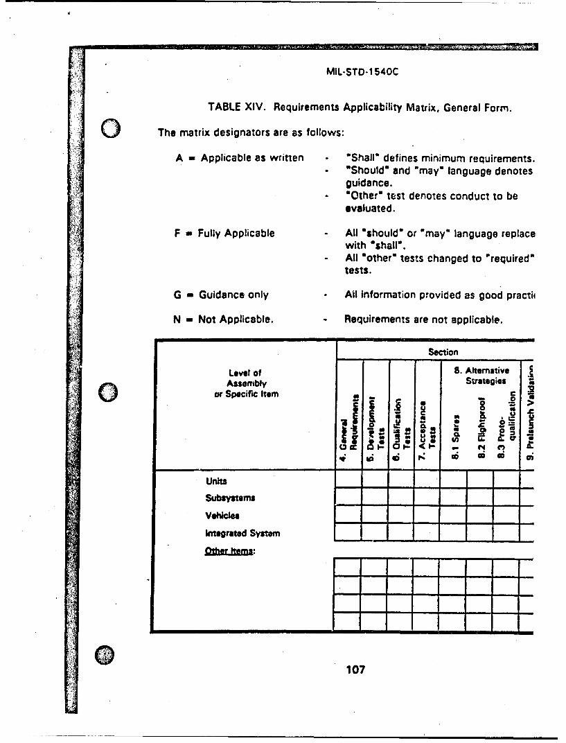
MIL-STD-1540C
TABLE XIV. Requirements Applicability Matrix, General Form.
The matrix designators are as follows:
A - Applicable as written "Shall" defines minimum requirements."Should* and "may" language denotesguidance." Other" test denotes conduct to beevaluated.
F - Fully Applicable All "should" or 'may" language replace;with %shall'.All 'other" tests changed to "required"tests.
G - Guidance only All information provided as good practii
N - Not Applicable. Requirements are not applicable.
Section
Levil of 8. AlternativeAssembly Strategies
UrduU
or Specific Item00
Units- - -- - - -
Subsystems
Veicles
Integrated System
Ote Itms
I 0
! 107
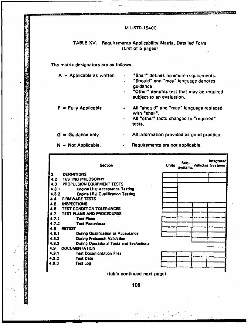
MoL-STD- 1540CC
TABLE XV. Requirements Applicability Matrix, Detailed Form.(first of 5 pages)
The matrix designators are as follows:
A -Applicable as written OShalla defines minimum rquirements."Should' and *maya language denotesguidance.
"-Other* denotes test that may be requiredsubject to an evaluation.
F - Fully Applicable - All "should" and *maym language replacedwith *sha~l¶w
*All motherm tests changed to "required'tests.
G = Guidance only - All information provided as good practice.
N - Not Applicable. - Requirements are not applicable.
section Units stesVehicI.s Systemst
3. DEFINITONS-4.2 TESTING PHILOSOPHY4.3 PROPULSION EQUIPMENT TESTS-4.3.1 Engine LRU Acceptance Testing4.3.2 Engine LRU Oualification Testing4.4 FIRMWARE TESTS4.5 INSPECTIONS 14.6 TEST CONDITON TOLERANCES- - - -
4.7 TEST PLANS AND PROCEDU~RES- --
471 Test Plans - - -
4.7.2 Test Procedures- - - -
481 During Qualification or Acceptance - -
4.8.2 During Prelaunch Validation -
4.8.3 During Operational Tests and Evaluations- -
4.9 DOCUMENTATION4.3.1 Test Documentation Files ~-4.9.2 Test Data - -
4.9.3 Test Log -I-I
(table continued next page)
108
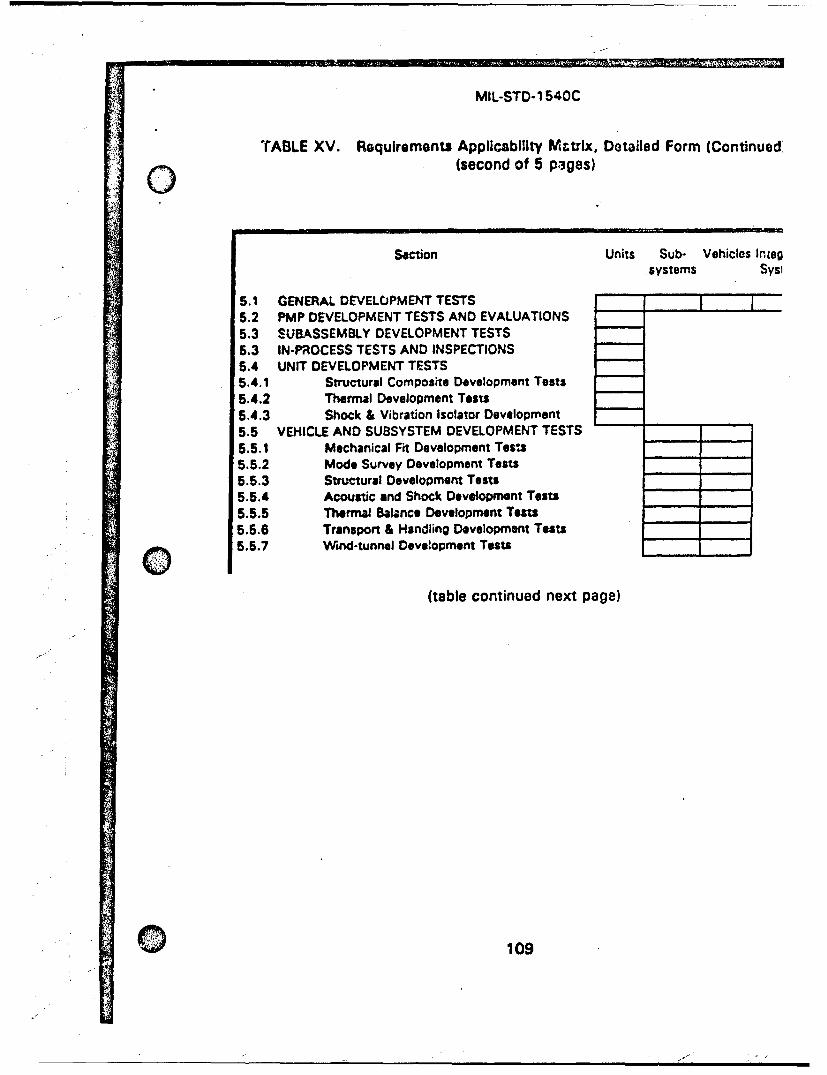
2;9=
MIL-STD-1 540C
TABLE XV. Requirements Applicability MWtrix, Detailed Form (Continued,C (second of 5 pages)
Section Units Sub- Vehicles Inlegsystems Sysi
5.1 GENERAL DEVELOPMENT TESTS5.2 PMP DEVELOPMENT TESTS AND EVALUATIONS5.3 SUBASSEMBLY DEVELOPMENT TESTS5.3 IN-PROCESS TESTS AND INSPECTIONS5.4 UNIT DEVELOPMENT TESTS5.4.1 Structural Composite Development Tests5.4.2 Thermal Development Tests5.4.3 Shock & Vibration Isolator Development5.5 VEHICLE AND SUBSYSTEM DEVELOPMENT TESTS -
5.5.1 Mechanical Fit Development Tess5.5.2 Mode Survey Development Tests5.5.3 Structural Development Tests -
5.5.4 Acoustic and Shock Development Tests - -
5.5.5 Thermal Balance Development Tests5.5.6 Transport & Handling Development Tests -.-
5.5.7 Wind-tunnel Development Tests -
(table continued next page)
109
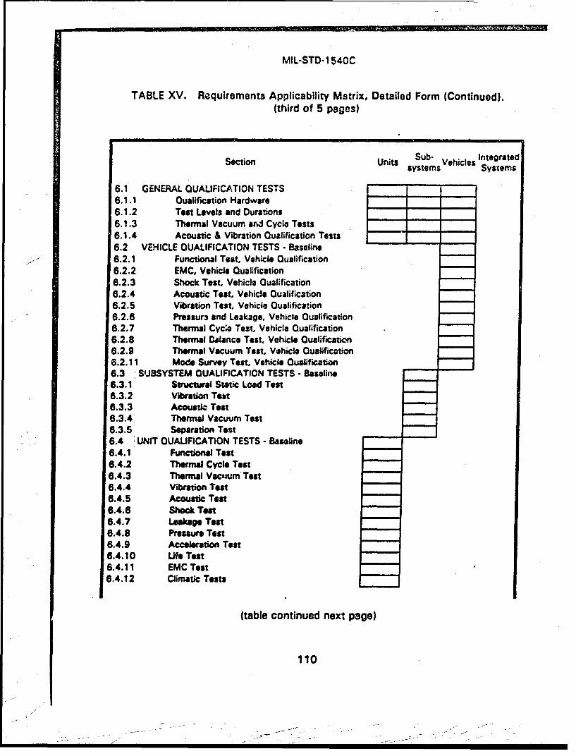
MIL-STD-1 540C
TABLE XV. Requirements Applicability Matrix, Detailed Form (Continued).(third of 5 pages)
Section Units Su-Vehicles Integr~atedsystems Systems
6.1 GENERAL QUALIFICATION TESTS- - -
6.1.1 Qualification Hardware- - -
6.1.2 Tesm Levels and Durations- - -
6 .1.3 Thermal Vacuum and Cycle Tests16.1.4 Acoustic & Vibration Qualification Tests6.2 VEHICLE QUALIFICATION TESTS - Baseline
--- 6.2.1 Functional Test, Vehicle Qualification6.2.2 EMC, Vehicle Qualification6.2.3 Shock Test, Vehicle Qualification6.2.4 Acoustic Test, Vehicle Qualification6.2.5 Vibration Test, Vehicle Qualification6.2.6 Pressurn and Leakage, Vehicle Qualification6.2.7 Thermal Cycle Test, Vehicle Qualification6.2.8 Thermal Balance Test, Vehicle Qualification6.2.9 Thermal Vacuum Test, Vehicle Qualification6.2.11 Mode Survey Test, Vehicle 0uslificat~on6.3 SUBSYSTEM QUALIFICATION TESTS.- Baseline6.3.1 Structural Static Load Test6.3.2' VibrationTeom6.3.3 Acoustic Test6.3.4 Thermal Vacuum Test6.3.5 Separation Test6.4 UNIT QUAUFICATION TESTS - Baseline6.4.1 Functional Test6.4.2 Thermal Cycle Test6.4.3 Thermal Vacuum Test6.4.4 Vibration Test6.4.5 Acoustic Tesg6.4.6 Shock Test6.4.7 Leakage Test6.4.8 Pressure Test6.4.9 Acceleation Test6.4.10 Life Test6.4.11 EMC Test6.4.12 Climatic Tests
(table continued next page)
110
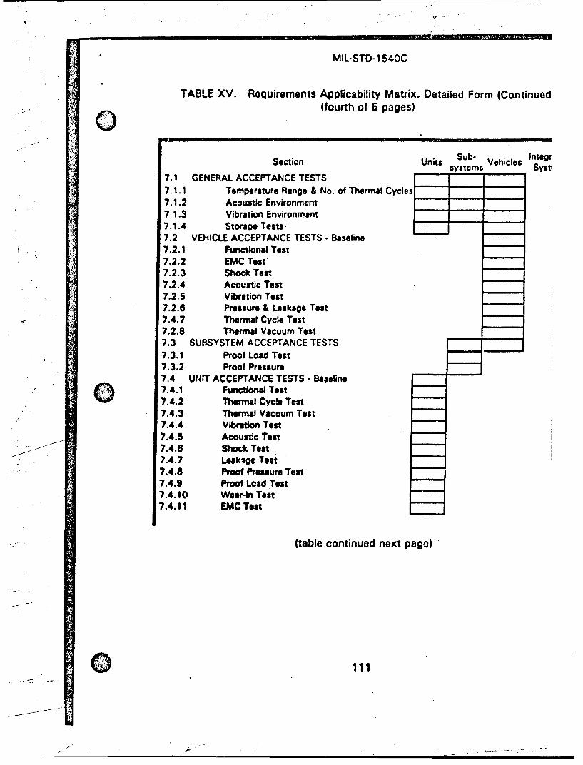
MIL-STD-1 540C
TABLE XV. Requirements Applicability Matrix, Detailed Form (Continuedo (fourth of 5 pages)
Section Units Sub- Vehicles Integfsystems Syst
7.1 GENERAL ACCEPTANCE TESTS7.1.1 Temperature Range & No. of Thermal Cycles7.1.2 Acoustic Environment7.1.3 Vibration Environmeant7.1.4 Storage Tests ....-.-7.2 VEHICLE ACCEPTANCE TESTS - Baseline7.2.1 Functional Test7.2.2 EMC Test7.2.3 Shock Test7.2.4 Acoustic Test7.2.5 Vibration Test7.2.6 Pressure & Leakage Test7.4.7 Thermal Cycle Test7.2.8 Thermal Vacuum Test7.3 SUBSYSTEM ACCEPTANCE TESTS7.3.1 Proof Load Test7.3.2 Proof Pressure7.4 UNIT ACCEPTANCE TESTS - Baseline7.4.1 Functonal Test7.4.2 Thermal Cycle Test7.4.3 Thermal Vacuum Test7.4.4 Vibration Test7.4.5 Acoustic Test7.4.6 Shock Test7.4.7 Leaksge Test7.4.8 Proof Pressure Test7.4.9 Proof Load Test7.4.10 Wear-in Test7.4.11 EMC Test
(table continued next page)
0 111
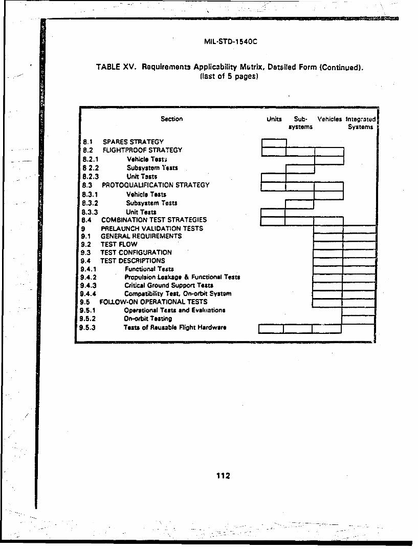
MIL-STD-1 540C
TABLE XV. Requirements Applicability Mutrix, Detailed Form (Continued).-i- -(last of 5 pages)
Section Units Sub- Vehicles Integratedsystems Systems
8.1 SPARES STRATEGY8.2 FLIGHTPROOF STRATEGY8.2.1 Vehicle Testi82.2 Subsystem Tests8.2.3 Unit T ests8.3 PROTOQUALIFICATION STRATEGY8.3.1 Vehicle Tests
8.3.2 Subsystem Tests8.3.3 Unit Tests8.4 COMBINATION TEST STRATEGIES9 PRELAUNCH VALIDATION TESTS9.1 GENERAL REQUIREMENTS9.2 TEST FLOW9.3 TEST CONFIGURATION -
9.4 TEST DESCRIPTIONS -
9.4.1 Functional Tests9.4.2 Propulsion Leakage & Functional Tests9.4.3 Critical Ground Support Tests9.4.4 Compatibility Test, On-orbit System9.5 FOLLOW-ON OPERATIONAL TESTS9.5.1 Operational Tests and Eveluations -.-
9.5.2 On-orbit Testing9.5.3 Tests of Reusable Flight Hardware
/.
112
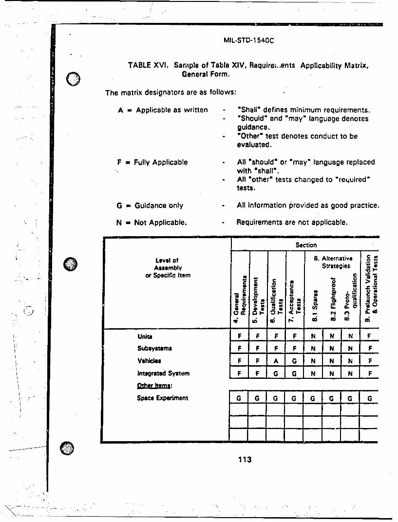
MIL-STD-1 540C
TABLE XVI. Sample of Table XIV, Requirei,,ents Applicability Matrix,0 General Form.
The matrix designators are as follows:
A = Applicable as written "Shall" defines minimum requirements.-. 'Should" and "may" language denotes
guidance."Other" test denotes conduct to beevaluated.
F = Fully Applicable All "should" or "may" language replacedwith "shall".
SAll "other" tests changed to *re.4uired"tests.
G = Guidance only All information provided as good practice.
N - Not Applicable. Requirements are not applicable.
Sectioni Level of 18. Alternative g
Assembly StrategiesortSpecific Item F F G G
•a ... ~
> 11
0..K) Q C
Units F F F F N N N FSubsystems F F F F N N N F
Vehicls F F A G N N N F
Integrated System F F G G N N NF
113
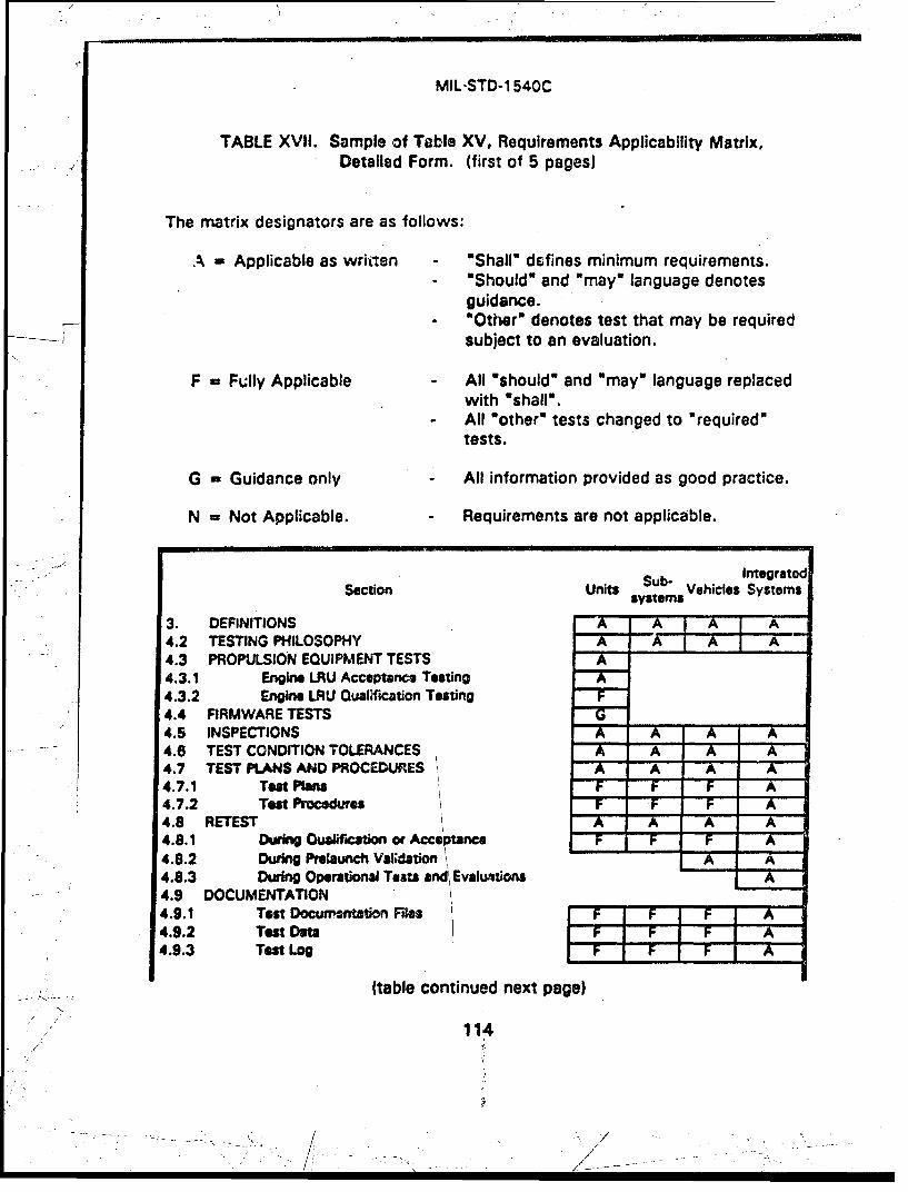
MIL-STD-1 540C
TABLE XVII. Sample of Table XV, Requirements Applicability Matrix,Detailed Form. (first of 5 pages)
The matrix designators are as follows:
A = Applicable as written "Shall" defines minimum requirements."Should' and "may" language denotesguidance.
* "Other" denotes test that may be requiredsubject to an evaluation.
F = Fully Applicable All "should" and "may" language replacedwith "shalln.All *other" tests changed to "required"tests.
G = Guidance only - All information provided as good practice.
N = Not Applicable. - Requirements are not applicable.
S... •"Sub- Integrate
Section Units sub- Vehicles SystemssystemsSytm
3. DEFINITIONS A A A A4.2 TESTING PHILOSOPHY A A A A4.3 PROPULSION EQUIPMENT TESTS4.3.1 Engine LRU Acceptrnce Testing4.3.2 Engine LRU Qualification Testing4.4 FIRMWARE TESTS G4.5 INSPECTIONS A A A A4.6 TEST CONDITION TOLERANCES A A A A4.7 TEST PLANS AND PROCEDURES _7X_ A -A A4.7.1 Test Plans F F F A4.7.2 Test Procdures F F F A4.8 RETEST AiX -A X-4.8.1 During Oualif'rion or Accertance F F T A4.8.2 During Prelaunch Val;dation A A4.8.3 During Operational Tests and Evaluntions A4.9 DOCUMENTATION4.9.1 Test Docurr-ntation Files F F F A4.9.2 Test Data F F F A4.9.3 Test Log F F F A
(table continued next page)
"114
I - /
S• . , /~~~~~.,". i,. . .. .
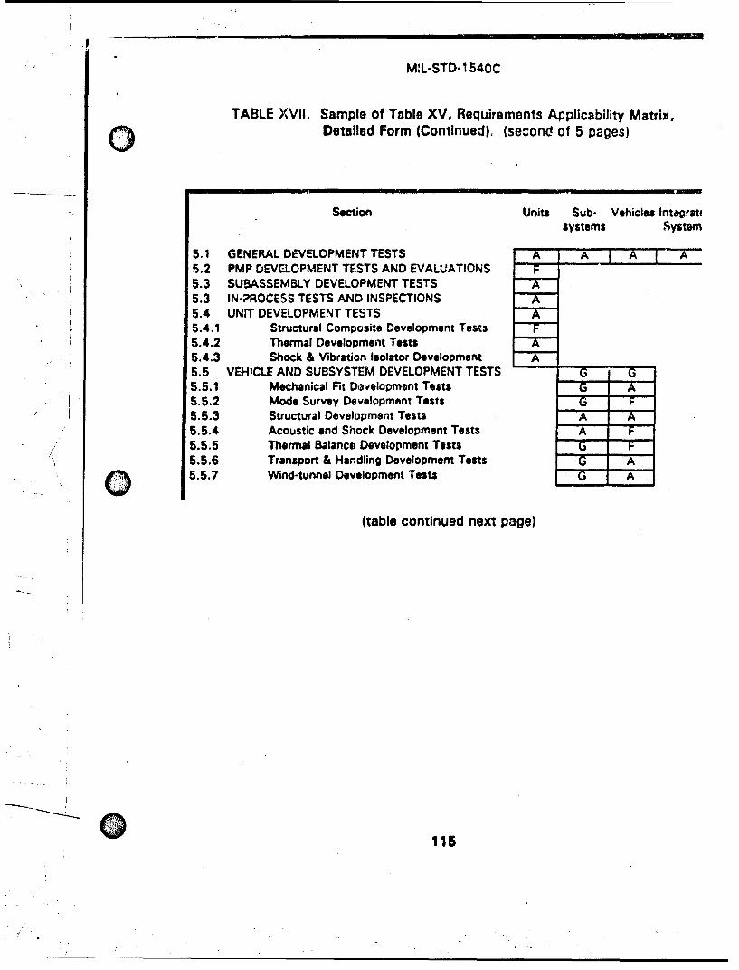
M:L-STD-1540C
TABLE XVIi. Sample of Table XV, Requirements Applicability Matrix,Q Detailed Form (Continued). (second of 5 pages)
Section Units Sub- Vehicles Intagratfsystems ,ystern
5.1 GENERAL DEVELOPMENT TESTS A A A r A5.2 PMP DEVELOPMENT TESTS AND EVALUATIONS F
5.3 SUBASSEMBLY DEVELOPMENT TESTS5.3 IN-PROCESS TESTS AND INSPECTIONS A5.4 UNIT DEVELOPMENT TESTS5.4.1 Structural Composite Development Tests5.4.2 Thermal Development Tests5.4.3 Shock & Vibration Isolator Development A5.5 VEHICLE AND SUBSYSTEM DEVELOPMENT TESTS G G5.5.1 Mechanical Fit Development Tests G A5.5.2 Mode Survey Development Tests G F5.5.3 Structural Development Tests A A5.5.4 Acoustic and Shock Development Tests A F5.5.5 Thermal Balance Development Tests G F5.5.6 Transport & Handling Development Tests G A5.5.7 Wind-tunnel Development Tests G A
(table continued next page)
115
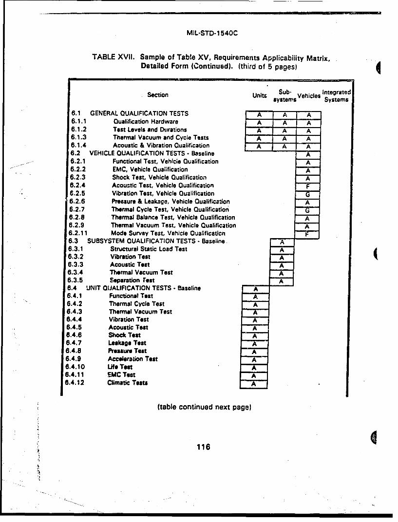
MIL-STD-1540C
TABLE XVII. Sample of Table XV, Requirements Applicabiiity Matrix,Detailed Form (Continued). (third of 5 pages)
Section Units Sub- ehi ces Integratedsystem ncs Systems
6.1 GENERAL QUALIFICATION TESTS A A A6.1.1 Qualification Hardware A A A6.1.2 Test Levels and Durations A A A6.1.3 Thermal Vacuum and Cycle Tests A A A6.1.4 Acoustic & Vibration Qualification A A A6.2 VEHICLE QUALIFICATION TESTS - Baseline A6.2.1 Functional Test, Vehicie Qualification A6.2.2 EMC, Vehicle Qualification A6.2.3 Shock Test, Vehicle Qualification A6.2.4 Acoustic Test, Vehicle Qualification F6.2.5 Vibration Test, Vehicle Qualification6.2.6 Pressure & Leakage, Vehicle Qualification A6.2.7 Thermal Cycle Test, Vehicle Qualification G6.2.8 Thermal Balance Test, Vehicle Qualification A6.2.9 Thermal Vacuum Test, Vehicle Qualification A6.2.11 Mode Survey Test, Vehicle Qualificaticn6.3 SUBSYSTEM QUALIFICATION TESTS - Baseline A6.3.1 Structural Static Load Test A6.3.2 Vibration Test A6.3.3 Acoustic Test A6.3.4 Thermal Vacuum Test A6.3.5 Separation rest A6.4 UNIT QUALIFICATION TESTS - Baseline A6.4.1 Functional Test A6.4.2 Thermal Cycle Test A6.4.3 Thermal Vacuum Test A6.4.4 Vibration Test A6.4.5 Acoustic Test A6.4.6 Shock Test A6.4.7 Leakage Test A6.4.8 Pressure Test A6.4.9 Accelera•ion Test A6.4.10 Life Test A6.4.11 EMC Tet A8.4.12 Climatic Tests A
(table continued next page)
116
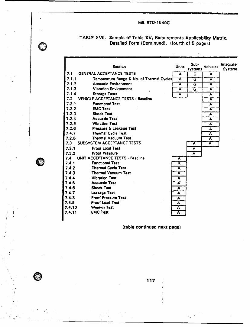
MIL-STD-1540C
TABLE XVIL. Sample of Table XV, Requirements Applicability Matrix,Detailed Form (Continued). (fourth of 5 pages)
Section Units Sub- Vehicles Integratetsystems Systemt
7.1 GENERAL ACCEPTANCE TESTS A G A7.1.1 Temperature Range & No. of Thermal Cycles A _G A7.1.2 Acoustic Environment A G A7.1.3 Vibration Environment A G A7.1.4 Storage Tests A A7.2 VEHICLE ACCEPTANCE TESTS - Baseline A7.2.1 Functional Test AiX_7.2.2 EMC Test A7.2.3 Shock Test A7.2.4 Acoustic Test A7.2.5 Vibration Test A7.2.6 Pressure & Leakage Test A7.4.7 Thermal Cycle Test A7.2.8 Thermal Vacuum Test A7.3 SUBSYSTEM ACCEPTANCE TESTS A A7.3.1 Proof Load lest A7.3.2 Proof Prassure A7.4 UNIT ACCEPTANCZE TESTS - Baseline7.4.1 Functional Test7.4.2 Thermal Cycle Test7.4.3 Thermal Vacuum Test A7.4.4 Vibration Test7.4.5 Acoustic Test A7.4.6 Shock Test A7.4.7 Leakage Teat A7.4.8 Proof Pressure Test A7.4.9 Proof Load Test A7.4.10 Wear-in Test A7.4.11 EMC Test
(table continued next page)
117
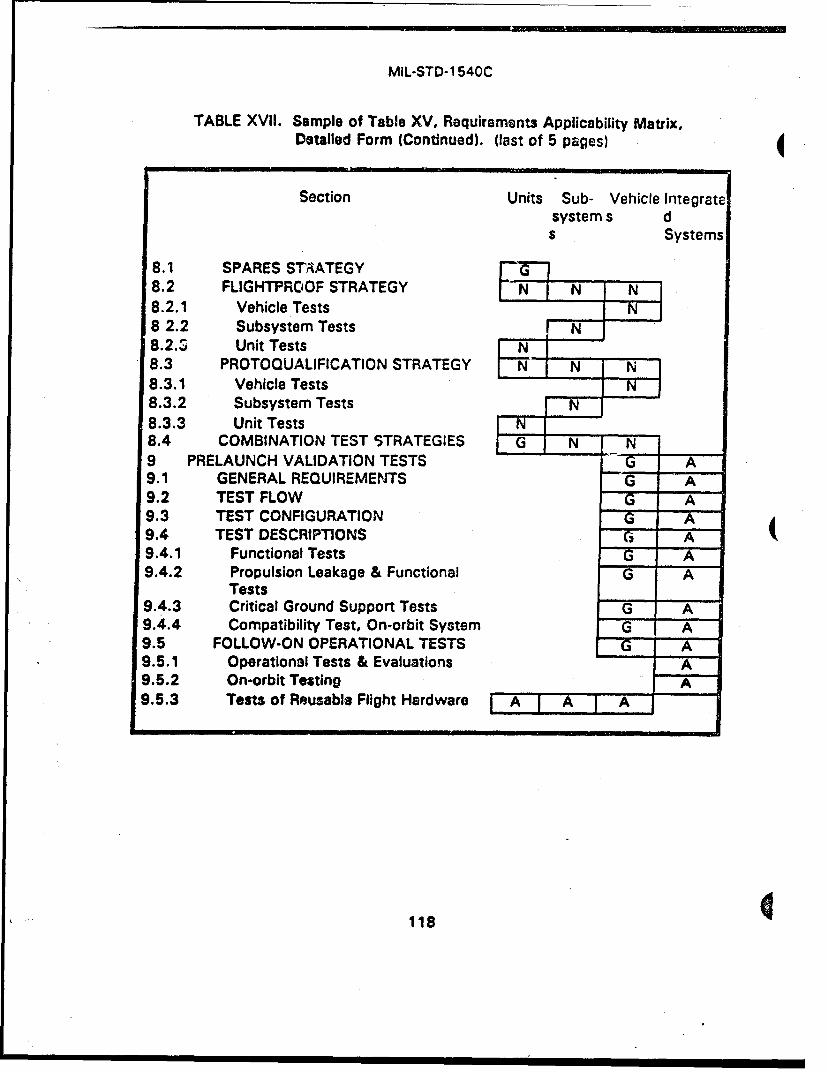
MIL-STD-1540C
TABLE XVII. Sample of Table XV, Requirements Applicability Matrix,Detailed Form (Continued). (last of 5 pages) 4
Section Units Sub- Vehicle Integratesystem s ds Systems
8.1 SPARES STVATEGY8.2 FLIGHTPROOF STRATEGY N I' N N8.2.1 Vehicle Tests8 2.2 Subsystem Tests N8.2.,S Unit Tests8.3 PROTOQUALIFICATION STRATEGY EN N N8.3.1 Vehicle Tests .. 1 NfF8.3.2 Subsystem Tests N8.3.3 Unit Tests N8.4 COMBINATION TEST STRATEGIES N N9 PRELAUNCH VALIDATION TESTS G A9.1 GENERAL REQUIREMENTS G A9.2 TEST FLOW G A9.3 TEST CONFIGURATION G A9.4 TEST DESCRIPTIONS G A9.4.1 Functional Tests G A9.4.2 Propulsion Leakage & Functional G A
Tests9.4.3 Critical Ground Support Tests G A9.4.4 Compatibility Test, On-orbit System G A9.5 FOLLOW-ON OPERATIONAL TESTS G A9.5.1 Operational Tests & Evaluations A9.5.2 On-orbit Testing A9.5.3 Tests of Reusable Flight Hardware A A A
118
MIL-STD-1 540C
10.3 TEST EVALUATION TEAM.
As a cost containment and quality assurance measure, it is stronglyrecommended that a joint contractor/procuring agency test evaluation teamestablished for each cf the major vehicle level tests, particularly the mode squalification test, the thermal balance qualification test, the subsystem stru,static load qualification test, and major separation qualification tests. The tconductor would typically be the chairman of the Test Evaluation Team. O1members should be provided by the design organization that will use the reiby safety, and by quality assurance. The procuring agency should providequalified technical representative to the team to perform the usual customeimonitoring of the test and to facilitate the timely approval of technically jusrminor deviations from the test requirements. The members of the team wotypically change for each test.
Formation of this team would be accomplished by the contract terms, Ias a Statement of Work (SOW) task. Suggested wording for the SOW is aifollows:
"xx.xxx Joint A encv/Cgntractor Test Evaluation Team. As a costcontainment and quality assurance measure, the contractor shall eia test evaluation team for the mode survey qualification test, the tbalance qualification test, and the (any other appropriate tests). TEvaluation Team shall:a. Evaluate the adequacy of the test configuration, including
instrumentation, prior to the start of testing.
b. Provide guidance in resolving technical problems and Issues ariduring testing.
c. Expedite the disposition of discrepancies and the approval ofcorrective actions, If required.
d. Verify adequacy of the test results.
*. Recommend tear-down of the test setup.
(The procuring agency) will provide a technical representative to thEvaluation Team to support team activities, monitor the test, and f;timely approval of technically justified or minor deviations from tesirequirements. In particular, during the mode survey test, the TestEvaluation Team may deviate from the completeness requirement fmodes judged to be unimportant, and from the orthogonality standiproblem modes. Such deviations require adequate technical justificand the concurrence of the designated representative of (the procuagency).*
119
MIL-STD-1 540C
10.4 IN-PROCESS CONTROLS.
In-process controls are almost always a more cost-effective way of avoidingdefects than the imposition of tests and inspections on completed units.Therefore, appropriate in-process controls and other quality management stepsshould be imposed to achieve the high-quality and reliability goals of space andlaunch systems. The acceptance testing requirements specified in this Standardare intended to be the last step in assuring the quality of each production item.When it has been thoroughly demonstrated that the purpose of an acceptancetesting requ'rement has been met by the in-process controls or other qualitymanagement steps implemented by the manufacturer, the manufacturer shouldpetition the procuring agency for approval to reduwe the test to a sampling test, orif appropri3te, for deletion of the test.
10.5 DOCUMENTATION.
Documents, forms, technical manuals, and data are prepared and distributed inaccordance with the Contract Data Requirements List (CDRL) of the applicablecontract. The data and data items discussed in this Standard are not deliverableunless invoked by the CDRL or the applicable contract..
The following Data Item Descriptions (DIDs) are among those most frequentlyused in the Contraui Data Requirements List (CDRL - DD Form 1423) to establish) •detail requirements for the preparation of test plans, procedures, and reports.
- Jum2b_ DDTitl.eDI-T-30714 Master Test Plan/Program Test Plan.DI-MCCR-80014A Software Test Plan.
DI-MCCR-80017A Software Test Report.
DI-ATTS-80041 Test Requirement Document.
DI-QCIC-8051 1 Installation Test Procedure.
DI-QCIC-80512 Installation Test Report.
DI-NDTI-80808 Test Plans/Procedures.
DI-NDTI-80809A Test/Inspection Reports.
DI-FACR-80810 Test Facility Requirement Document (TFRD).DI-ENVR-80861 Environmental Design Test Plan.
DI-MGMT-80882 Structural Test Plans.DI-MISC-80946 Launch Vehicle Post-Flight Analysis.
DI-MISC-80963 Reentry Vehicle Data Report.
DI-EMCS-81295 Electromagnetic Compatibility Test Plan.
120
- 7

MIL-STD-1 540C
10.6 GUIDANCEDOCUMENTS
0MIL-HDBX-340 Application Guidelines for MIL-STD-1 540; TestRequirements for Launch, .Upper-stage, and SpaceVehicles.
MIL-HDa;K-343 Design, Construction, and Testing Requirements forof a Kind Space Equipment.
MIL-STD-1 757 Lightning Qualification Test Techniques for AerospacVehicles and Hardware.
MIL-STD-1 795 Lightning Protection of Aerospace Vehicles and\ Hardware.
MIL-STD-1809 Standard Space Environment for Air Force Space
Vehicles.
DOD-STD-2167 Defense System Software Development.
"DOD-STD-2168 Defense System Quality Program.
DOD-E-83578 Explosive Ordnance for Space Vehicles, GeneralSpecification for.
MIL-A-83577 Assemblies, Moving Mechanical, for Space andLaunch Vehicles.
DNA-TR-84-140 Satellite Hardness and Survivability; Testing RationaMElectronic Upset and Burnout Effects.
10.7 MANA•,MENT OF OPERATIONAL TESTS AND EVALUATIONS
The Air Force Operational Test and Evaluation Center (AFOTEC) managesForce operational tests and evaluations (OT&E) as directed or designated in onits three levels of involvement:
a. Conducts OT&E.b. Monitors OT&E.c. Provides advisory role In the conduct of OT&E.
10.8 SUBJECT TERM (KEY WORD) LISTING
Acceptance SoftwareDevelopment Test BaselineHardware Test PlanInspections Test ProcedureOperational Test StepQualification TestingRecords Test Requirements
.121
.- •_ , ,. . t .1•
MIL-STD-1540C
10.9 CHANGES FROM PREVIOUS ISSUES Marginal notations are not used inthis revision to identify changes with respect to the previous issue due to theextensiveness of the changes. The title and content have been changed to showextension of the test requirements to launch vehicles and upper-stage vehicles.
Custodians Preparing ActivityAir Force - 19 Air Force - 19
(Project No. 1 810-F049)
122
Al
A4
./ -. - -... . . . '
S- /~ ~~ , \ > ,)-. ,
"/" -. I 7 I II I.
MIL-STD-1540C
C)INDEX
Accelerated testing, dynamic qualificstion 34 therrhal uncertainty margins, subsystAcceleration test, unit qualification 66 Data item descriptions (DIDs) 120Acceleration, maximum predicted 11 Development testAcceptance test acoustic 27
baseline article for 5levels & durations, typical 73 mechanical fit 26units 85 mode survey 26vehicles 79 part, material, process (PMP) 24
general requirements 72 purpose 23isolator, special considerations 89 shock 27special tests 35, 53 shock & vibration isolator 26storage 75 structural 26subsystem 83 structural composite 25unit 84 subassembly 24vehicle 75 subsystem 26
Acoustic environment thermal 25extreme & maximum expected 9 thermalsbalance 27
Acoustic test transportation & handling 28acceptance spectrum 75 unit 24
minimum 76 vehicle 26qualification margin & duration 31 wind tunnel 28replacement by vibration 40, 50, 79, 81 Discrepancy, test 14subsystem qualification 51 Documentationtolerances 18 deliverability 120unit test data 22
-crtpPtance 88 test documentation file 22qualification 62 test log 22
"vehicle test procedures 20acceptance 80 Electrical & fiber-optic circuit testqualification 39 vehicle qualification 36
Airborne support equipment 4 Electromagnetic compatibility testAlternative strategy 15 launch-critical ground support equiprr
combination 96 unitdiscussion 105 acceptance 91flightproof 93 qualification 68protoqualification 94 vehicle qualification 37rationale 92 Environmental stress screening 32, 59,spares 92 Explosive atmosphere test
Ambient environment 13 unit qualification 71Appication of Standard 1 Explosive ordnance
guidelines in MIL-HDBK-340 121 device definition 5Items covered 104 DOD-E-83578 121test categories 1 electromagnetic compatibility 38
"Burst prelaunch validation 99design pressure 10 launch-critical ground support equfactor 10 100
Climatic tests, unit qualification 68 Failure, test item 14Combination tes strategles 96 Fairing separation testCompatibility test, on-orbit system 100 subsystem qualification 52Contamination tolerance 13 Fatigue 9, 13, 15, 92, 93Cryogenic inspection after qualification life test
acceptance temperature range, units 72 life factor 32qualification margins, units 57 structural units 61
123
MIL-STD-1 540C
INDEX
life test, unit qualification 67 pressure test, vehicle qualification 41margin 67 static loads, qualification 31
low for structural units 94 static load test, subsystem qualification 50structural qualification 61 subsystem protoqualification 95
thermal cycling 31, 33 Margins, thermal (see Thermal margins)Fatigue equivalent duration 32. 39. 60, 61 Maximum expected operating pressure (MEOP)
definition 9 definition 11Firmware tests 17 Mechanical functional testFlightproof strategy 93 vehicle qualification 35
subsystem tests 94 Mode survey testunit tests 94 development 26vehicle tests 93 Test Evaluation Team 119
Follow-on operational tests 101 vehicle qualification 46reusable flight hardware 102 Moving mechanica, assembly (MMA)
Functional test definition 5ground support equipment, disassembly & inspection after life test 67
launch-critical 100 margins, measurement 6uri.j thermal vacuumprelaunch validation 99 testing 60propulsion subsystem MIL-A-83577 121
prelaunch validation 100 monitoring during thermal vacuum test 60unit multiple categcries 84
acceptance 84 performance monitoringqualification 53 unit thermal vacuum acceptance 88
vehicle unit qualification, conditions 53, 55acceptance 75 Notes for government use of Standard 103qualification 35 On-orbit system
Ground support equipment, launch-critical compatibility test 100prelaunch validation tests 100 follow-on operational tests 101
Guidance documents 121 One-of-a-kind equipment, MIL-HDBK-343 121Humidity test, unit qualification 63 Operational deflections 11In-process controls 120 Operational modes 13Inspections 17 Operational tests and evaluations 1, 16Integrated system tests 16 management 121Isolator acceptance "Other" test
special considerations 88 definition 13Key word, listing 122 discussion 104Leakage test Prelaunch validation tests 16
propulsion subsystem general requirements 97prelaunch validation 100 ground support equipment, launch-critical 100qualification 41 grounding 98
unit test configuration 98acceptance 90 test descriptions 99qualification 84 test flow 98
Life test Pressure & leakage tests, vehiclemoving mechanical asserbly acceptance 81
development 25 qualification 40unit qualification 66 Pressure component, definition 12
i.ghtning protection (MIL-STD-1 795) 121 Pressure for structural testLUmit load, definition 11 burst factor, deflnition 10Loads for structural test, definitions 11 design burst, definition 10Margins, structural csign factor of safety, definition 10
acceleratk•m test, unit qualification 68 maximum expected operating, definition 11prssure tiet, unit qulification 65
124
MIL-STD-1540C
INDEX
Pressure test Reusable flight hardwarequalification pressure & durt:ion 41 definition 5unit qualification 64 follow-on operational tests 102
Pressure vessel, definition 12 Salt fog test, unit qualification 71Pressurized structure, definition 12 Sand & dust test, unit qualification 70Pressurized subsystem, definition 12 Separation testProof subsystem qualification 17, 52
factor 12 Test Evaluation Team 119test, definition 12 Service life, definition 14load test, acceptance Shock environment
structural component 89 extreme & maximum expected 10structural subsystem 83 Shock test
pressure test qualificationpressurized subsystem acceptance 84 activations, vehicle 38unit acceptance 90 levels & number of shocks, typica!
success criteria 12 tolerances 18Propulsion equipment tests 16 unitProtoqualification strategy acceptance 89
subsystem tests 95 qualification 62unit tests 95 vehiclevehicle tests 95 acceptance 80
Ouslification test qualification 38acceleration of acceptance. dynamic tstinq Sinusoidal vibration environment
34 extreme & maximum expected 9acoustic 32 Spares strategy 92basline Special tests 35, 53
units 53,54 Static load testvehicles 35 qualification load factors 31
general requirements 30 subsystem qualification 49hardware 30 Test Evaluation Team 119levels & durations, general 30 Statistical estimatesmargin requirement for qualification 14
definition 13 shock, vibration, acoustic environmetand durations, typical 31 Storage tests, acceptance 75cryogenic exposure, units 57 Structural component, definition 12
required prior testing 30 Structural testrequirements, multiple unit categories 53 static load, subsystem qualificationspecial tests 35, 53 tolerances 18vibration 32 Subsystem qualification tests 48
Rain test, unit qualifiration 71 Tailoring 103Random vibration environment examples 114
extreme & maximum expected 9 see Requirements Applicability Matri:Required tests, discussion 104 TemperatureRequiremenets Applicabiity Matrix maximum & minimum expected 5
detaled form 108-112 rarge for cycling 72"sample 114-118 predicted & test ranges, unit 74
general form 107 stabilization, definition 14sa-mple 113 Test
ee 20 allowable toerances 17, 18during operational tests & eva!,'|tions 21 categories 1during prelaunch validation 21 data documentation 22during qualification or acceptance 21 discrepancy 14
documentation fides 22
"125
-_o_. o, //
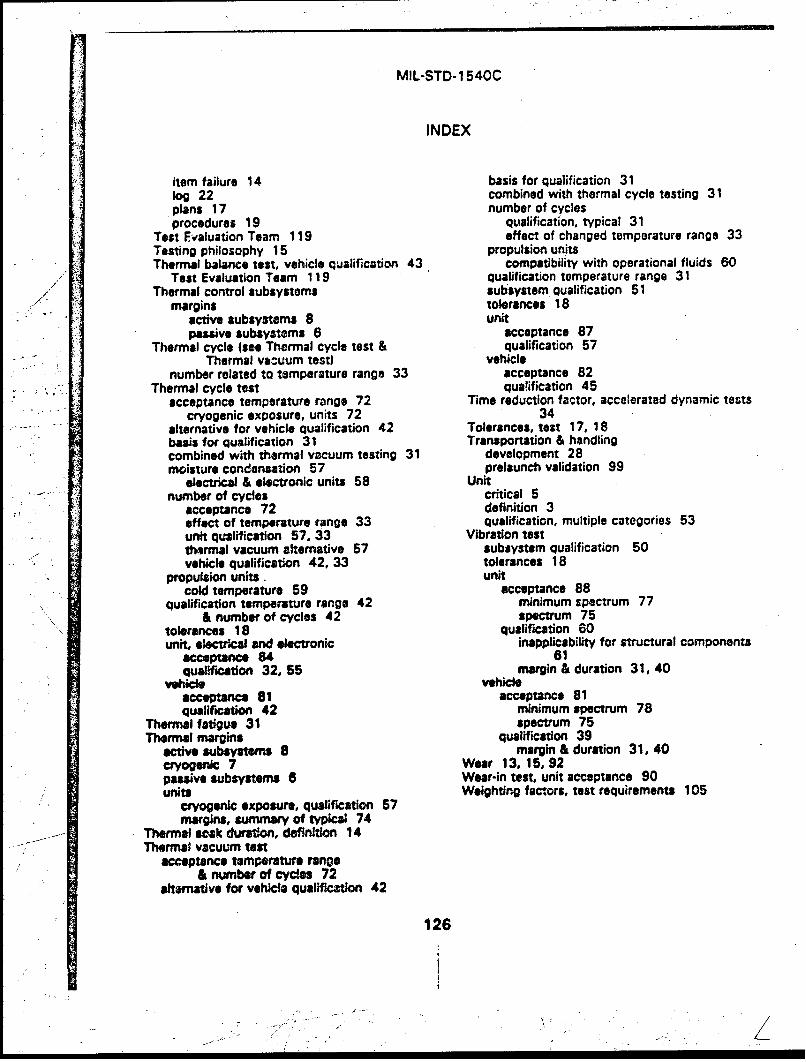
MIL-STD-1 540C
INDEX
item failure 14 basis for qualification 31log 22 combined with thermal cycle testing 31plans 17 number of cyclesprocedures 19 qualification, typical 31
Test Evaluation Team 119 effect of changed temperature range 33Testing philosophy 15 propulsion unitsThermal balance test, vehicle qualification 43 compatibility with operational fluids 60
Teat Evaluation Team 119 qualification temperature range 31Thermal control subsystems subsystem qualification 51
.- margins tolerances 18"active subsystems 8 unitpawve subsystems 6 acceptance 87
Thermal cycle (see Thermal cycle test & qualification 57Thermal vacuum test) vehicle
number related to temperature range 33 acceptance 82Thermal cycle test qua!ification 45
acceptance temperature range 72 Time reduction factor, accelerated dynamic testscryogenic exposure, units 72 34
alternative for vehicle qualification 42 Tolerances, test 17, 18basis for qualification 31 Transportation & handlingcombined with thermal vacuum testing 31 development 28moisture condensation 57 prelaunch validation 99
electrical & electronic units 58 Unitnumber of cycles critical 5
acceptance 72 definition 3effect of temperature range 33 qualification, multiple categories 53unit qualification 57, 33 Vibration testthermal vacuum alternative 57 subsystem qualification 50vehicle qualification 42, 33 tolerances 18
propulsion units. unitcold temperature 59 acceptance 88
qualification temperature range 42 minimum spectrum 77& number of cycles 42 spectrum 75
tolerances 18 qualification 60unit, electrical and electronic inapplicability for structural components
acceptance 84 61qualIfication 32, 55 margin & duration 31, 40
vehide vehideacceptance 81 acceptance 81qualification 42 minimum spectrum 78
Thermal fatigue 31 spectrum 75Thermal margins qualification 39
active subsystems 8 margin & duration 31, 40cryogenic 7 Wear 13. 15, 92passive subsystems 6 Wear-in test, unit acceptance 90units Weighting factors, test requirements 105
creyognic exposure, qualification 57margins, u•mmary of typical 74
Thermal soak duration, definition 14Thermal vacuum test
acceptance temperature range& number of cycles 72
alternative for vehicle qualification 42
126
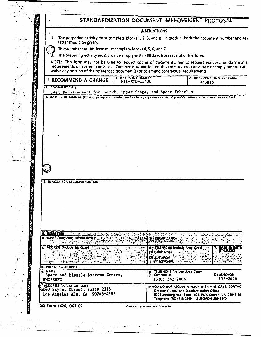
STANDARDIZATION DOCUMENT 114PROVEWENT PROPO0S'A
INSTRUCTIONS
1. The preparing activity must complete blocks 1, 2. 3. and 8. in block 1, both the document number and re%letter should be given.QThe submitter of this form must complete blocks 4, 5, 6, and 7.The preparing activity must provide a reply within 30 days from receipt of the form.
NOTE: This form may not be used to request copies of documents, nor to request waivers, or clarificaticrequirements on current contracts. Comments submitted on this form do not constitute or imply authorizati(waive any portion of the referenced documnent(s) or to amend contractual requirements.
I RECOMMEND A CHANGE: 1i. DOCUMENT NUMBER j.DOCUMENT DATE (YYMMOD)ý . . 1 ý I I Mll-TD-540C7 1. 940915
3. DOCUMENT TITLE
Test Requirements for Launch, Upper-Stage, and Space Vehicles4. NATURE OF CHANGE (identify piaragraph number and include proposed rewrite, it possibM*. Attach efltra sheets as neeoled.)
S. REASON FOR RECOMMENDATION
S.SUBMITTilt
C. ADOORSS tkln~o* Zip Cod*). IV Th.EP$ONlEJ f*K Area Code) 7.DATA SUMtTTTI
B. PREPARING ACTIVITY
a. NAMEb TELEPHONE (Include Area Code)Space and Missile Systems Center, (( omeca 2) AUTOVON
SM/DC(310) 363-2406 833-2406
0U SkIncue Ztiet Suite) 21 IF YOU 00 NOT RECEIVE A REPLY WITHIN 45 DAYS. CONTAC0o kn~ele Stree, CA ite02315-8 Defense Quality and Standardization Office
Los ngees AB, A 9045-6835203 Leesburg Pike, Svite 1403. Falls Church. VA 22041.34Telephone (703) 756-2340 AUTIOVON 259-2310
DO Form 1426, OCT 89 Previous edstions are obsolete.

![INFCIRC 540c II HB INFCIRC 254 1 HB INFCIRC 254 2 ... - Europa · Dual-use equipment and materials listed in the NSG guidelines Part 2 [5]. References to the NSG exist in several](https://img.pdfslide.us/doc/110x75/60719199a00de01672150115/infcirc-540c-ii-hb-infcirc-254-1-hb-infcirc-254-2-europa-dual-use-equipment.jpg)