Embed Size (px)
Citation preview
ii. AdvAnced combustion And emission control reseArch For high-eFFiciencY engines C. Critical Enabling Technologies
FY 2007 Progress Report 20� Advanced Combustion Engine Technologies

Advanced Combustion Engine Technologies 202 FY 2007 Progress Report
II.C.1 Variable Valve Actuation for Advanced Mode Diesel Combustion
Jeffrey Gutterman P.E. Delphi Corporation 5500 West Henrietta Rd. PO Box 20366 Rochester, NY 14602-0366
DOE Technology Development Manager: Roland Gravel
NETL Project Manager: Jason Conley
Subcontractor: Electricore Inc., Valencia, CA
Objectives
• Develop an optimal, cost-effective, variable valve actuation (VVA) system for advanced low-temperature diesel combustion processes.
• Design and model alternative mechanical approaches and down-select for optimum design.
• Build and demonstrate a mechanism capable of application on running engines.
Accomplishments
• Confirmation that a single cam design did not have the required control flexibility to meet requirements.
• Three dual cam design concepts were developed and modeled.
• A dual cam design was selected from concept designs and all dynamic analyses were completed.
• An original equipment manufacturer (OEM) confirmed that the proposed dual cam design is a cost-effective and production feasible design.
• Package size was reduced to require minimal change to OEM engine envelope.
• Advanced VVA math-based design process was introduced and design tools are now available for future modeling work.
• All of critical design analyses for high stress subcomponents including springs, bearings, gears and output rocker cam were completed.
• The mechanical actuator (cam phaser) development engineering work was completed and prints prepared.
• Cam phaser controller with proportional, integral, and derivative control capability built and tested.
• A single-cylinder device was built and installed on a free running lab engine.
Future Directions
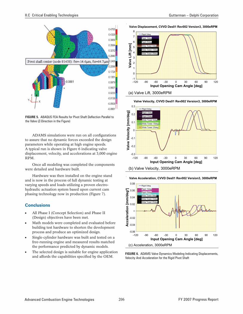
• Recent continuously variable valve duration (CVVD) assembly finite element analysis (FEA) analysis results indicate the potential for output rocker cam pivot shaft deformation. Design enhancements will be integrated to improve stiffness and eliminate the variation.
• OEM engine in-cylinder air flow analysis using the Star-CD computational fluid dynamics (CFD) program is underway. Further analysis of the effect of the CVVD modified valve lift on air charge efficiency and swirl, will establish benefits of CVVD.
• Accelerated durability testing of mechanism.
• Dynamometer testing while monitoring exhaust emissions on running engines will verify benefits predicted by CFD modeling.
G G G G G
introduction
Our objective is to develop and demonstrate an optimal cost-effective diesel VVA system for advanced, low-temperature combustion processes. Flexible control of the valve event is a significant enabler for advanced mode diesel combustion (AMDC). It is an essential factor in the control of the species and thermodynamic conditions for the combustion cycle. VVA is expected to enable expanding the operating load and speed range of AMDC. It is also a potential tool for enhancing the effectiveness of aftertreatment catalysts. Thus, viable VVA technology is expected to help in reducing the penalty in fuel consumption related to extremely low emission standards.
Delphi Corporation has major manufacturing and product development and applied R&D expertise in thee valvetrain area. Historical R&D experience included the development of fully variable electrohydraulic valvetrain on research engines as well as several generations of mechanical VVA for gasoline systems. A new mechanism was taken from concept stage through design, modeling, build and bench testing on a single-cylinder engine test stand.
FY 2007 Progress Report 20� Advanced Combustion Engine Technologies
II.C Critical Enabling Technologies Gutterman – Delphi Corporation
Approach
Working with an OEM was critical to determine the mechanism motion requirement and system specifications. To speed development, significant time was spent using advanced design tools and simulations before building the actual hardware. After modeling more than 200 variations of the mechanism it was determined that the single cam design did not have enough flexibility to satisfy three critical OEM requirements simultaneously, (maximum valve lift variation, intake valve opening timing and valve closing duration), and a new approach would be necessary.
Internal design reviews, including three with the OEM, resulted in a dual cam design that had the flexibility to meet all motion requirements. The second cam added complexity to the mechanism however the cost was offset by the simplification of the actuator subsystem.
Once the design was dynamically simulated and the FEA was completed, single-cylinder hardware was built and installed on a free-running engine test stand to verify predicted performance.
results
Critical performance parameters were supplied by an OEM that had to be met before the mechanism could be applied to their engine. The previously detailed GEMS design was a single cam device
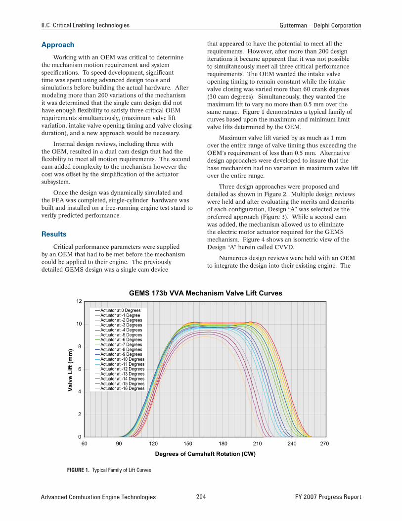
that appeared to have the potential to meet all the requirements. However, after more than 200 design iterations it became apparent that it was not possible to simultaneously meet all three critical performance requirements. The OEM wanted the intake valve opening timing to remain constant while the intake valve closing was varied more than 60 crank degrees (30 cam degrees). Simultaneously, they wanted the maximum lift to vary no more than 0.5 mm over the same range. Figure 1 demonstrates a typical family of curves based upon the maximum and minimum limit valve lifts determined by the OEM.
Maximum valve lift varied by as much as 1 mm over the entire range of valve timing thus exceeding the OEM’s requirement of less than 0.5 mm. Alternative design approaches were developed to insure that the base mechanism had no variation in maximum valve lift over the entire range.
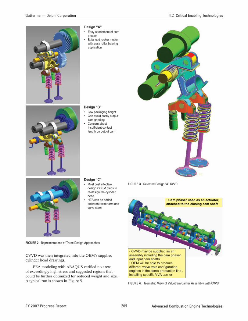
Three design approaches were proposed and detailed as shown in Figure 2. Multiple design reviews were held and after evaluating the merits and demerits of each configuration, Design “A” was selected as the preferred approach (Figure 3). While a second cam was added, the mechanism allowed us to eliminate the electric motor actuator required for the GEMS mechanism. Figure 4 shows an isometric view of the Design “A” herein called CVVD.
Numerous design reviews were held with an OEM to integrate the design into their existing engine. The
GEMS 173b VVA Mechanism Valve Lift Curves 12
10
8
6
4
2
0
Actuator at 0 DegreesActuator at -1 DegreeActuator at -2 DegreesActuator at -3 DegreesActuator at -4 DegreesActuator at -5 DegreesActuator at -6 DegreesActuator at -7 DegreesActuator at -8 DegreesActuator at -9 DegreesActuator at -10 DegreesActuator at -11 DegreesActuator at -12 DegreesActuator at -13 DegreesActuator at -14 DegreesActuator at -15 DegreesActuator at -16 Degrees
60 90 120 150 180 210 240 270
Degrees of Camshaft Rotation (CW)
FiGure 1. Typical Family of Lift Curves
Valv
e Li
ft (m
m)
Advanced Combustion Engine Technologies 20� FY 2007 Progress Report
Gutterman – Delphi Corporation II.C Critical Enabling Technologies
Design “A” • Easy attachment of cam
phaser • Balanced rocker motion
with easy roller bearing application
Design “B” • Low packaging height • Can avoid costly output
cam grinding • Concern about
insufficient contact length on output cam
FiGure 3. Selected Design “A” CVVD Design “C” • Most cost effective
design if OEM plans to re-design the cylinder head
• HEA can be added between rocker arm and valve stem
FiGure 4. Isometric View of Valvetrain Carrier Assembly with CVVD
• Cam phaser used as an actuator, attached to the closing cam shaft
• CVVD may be supplied as an assembly including the cam phaser and input cam shafts • OEM will be able to produce different valve train configuration engines in the same production line , installing specific VVA carrier
FiGure 2. Representations of Three Design Approaches
CVVD was then integrated into the OEM’s supplied cylinder head drawings.
FEA modeling with ABAQUS verified no areas of exceedingly high stress and suggested regions that could be further optimized for reduced weight and size. A typical run is shown in Figure 5.
FY 2007 Progress Report 20� Advanced Combustion Engine Technologies
II.C Critical Enabling Technologies Gutterman – Delphi Corporation
Valve Displacement, CVVD Des01 Rev002 Version3, 3000eRPM 8
Rigid 0deg
Rigid 15deg
Rigid 25deg
Wide Tower 0deg
Wide Tower 15deg
Wide Tower 25deg
Valv
e Li
ft [m
m]
7
6
5
4
3
2
1
0
-1 -120 -90 -60 -30 0 30 60 90 120
Input Opening Cam Angle [deg]
(a) Valve Lift, 3000eRPM
Valve Velocity, CVVD Des01 Rev002 Version3, 3000eRPM 0.3
Rigid 0deg
Rigid 15deg
Rigid 25deg
Wide Tower 0deg
Wide Tower 15deg
Wide Tower 25deg Va
lve
Velo
city
[mm
/deg
]
FiGure 5. ABAQUS FEA Results for Pivot Shaft Deflection Parallel to the Valve (Z-Direction in the Figure)
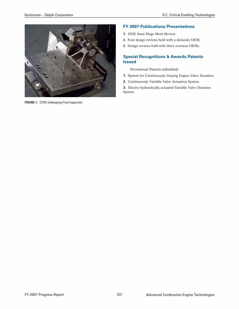
ADAMS simulations were run on all configurations to assure that no dynamic forces exceeded the design parameters while operating at high engine speeds. A typical run is shown in Figure 6 indicating valve
0.2
0.1
0
-0.1
-0.2
displacement, velocity, and accelerations at 3,000 engine -0.3 RPM. -120 -90 -60 -30 0 30 60 90 120
Input Opening Cam Angle [deg] Once all modeling was completed the components
were detailed and hardware built. (b) Valve Velocity, 3000eRPM
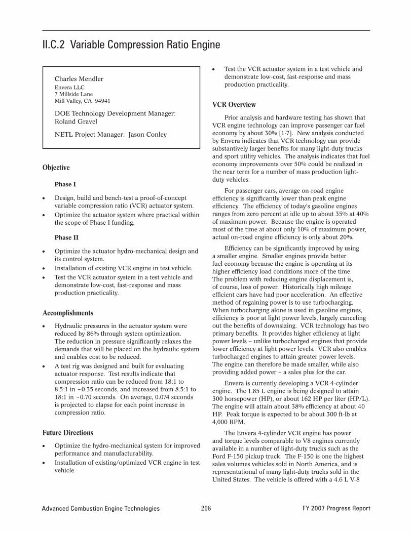
Hardware was then installed on the engine stand and is now in the process of full dynamic testing at
Valve Acceleration, CVVD Des01 Rev002 Version3, 3000eRPM 0.08 varying speeds and loads utilizing a proven electro- Rigid 0deg
Rigid 15deg
Rigid 25deg
Wide Tower 0deg
Wide Tower 15deg
Wide Tower 25deg
hydraulic actuation system based upon current cam phasing technology now in production (Figure 7).
conclusions
• All Phase I (Concept Selection) and Phase II (Design) objectives have been met.
• Math models were completed and evaluated before building test hardware to shorten the development A
ccel
erat
ion
[mm
/deg
²] 0.06
0.04
0.02
0
-0.02
-0.04
process and produce an optimized design.
• Single-cylinder hardware was built and tested on a free-running engine and measured results matched the performance predicted by dynamic models.
• The selected design is suitable for engine application and affords the capabilities specified by the OEM.
-0.06 -120 -90 -60 -30 0 30 60 90 120
Input Opening Cam Angle [deg] (c) Acceleration, 3000eRPM
FiGure 6. ADAMS Valve Dynamics Modeling Indicating Displacements, Velocity And Acceleration for the Rigid Pivot Shaft
Advanced Combustion Engine Technologies 20� FY 2007 Progress Report
Gutterman – Delphi Corporation II.C Critical Enabling Technologies
FY 2007 publications/presentations
1. DOE Semi-Mega Merit Review.
2. Four design reviews held with a domestic OEM.
3. Design reviews held with three overseas OEMs.
special recognitions & Awards/patents issued
Provisional Patents submitted:
1. System for Continuously Varying Engine Valve Duration.
2. Continuously Variable Valve Actuation System.
3. Electro-hydraulically actuated Variable Valve Duration System.
FiGure 7. CVVD Undergoing Final Inspection
FY 2007 Progress Report 207 Advanced Combustion Engine Technologies
II.C.2 Variable Compression Ratio Engine
Charles Mendler Envera LLC 7 Millside Lane Mill Valley, CA 94941
DOE Technology Development Manager: Roland Gravel
NETL Project Manager: Jason Conley
Objective
PhaseI
• Design, build and bench-test a proof-of-concept variable compression ratio (VCR) actuator system.
• Optimize the actuator system where practical within the scope of Phase I funding.
PhaseII
• Optimize the actuator hydro-mechanical design and its control system.
• Installation of existing VCR engine in test vehicle.
• Test the VCR actuator system in a test vehicle and demonstrate low-cost, fast-response and mass production practicality.
Accomplishments
• Hydraulic pressures in the actuator system were reduced by 86% through system optimization. The reduction in pressure significantly relaxes the demands that will be placed on the hydraulic system and enables cost to be reduced.
• A test rig was designed and built for evaluating actuator response. Test results indicate that compression ratio can be reduced from 18:1 to 8.5:1 in ~0.35 seconds, and increased from 8.5:1 to 18:1 in ~0.70 seconds. On average, 0.074 seconds is projected to elapse for each point increase in compression ratio.
Future Directions
• Optimize the hydro-mechanical system for improved performance and manufacturability.
• Installation of existing/optimized VCR engine in test vehicle.
• Test the VCR actuator system in a test vehicle and demonstrate low-cost, fast-response and mass production practicality.
VCR Overview
Prior analysis and hardware testing has shown that VCR engine technology can improve passenger car fuel economy by about 30% [1-7]. New analysis conducted by Envera indicates that VCR technology can provide substantively larger benefits for many light-duty trucks and sport utility vehicles. The analysis indicates that fuel economy improvements over 50% could be realized in the near term for a number of mass production light-duty vehicles.
For passenger cars, average on-road engine efficiency is significantly lower than peak engine efficiency. The efficiency of today’s gasoline engines ranges from zero percent at idle up to about 35% at 40% of maximum power. Because the engine is operated most of the time at about only 10% of maximum power, actual on-road engine efficiency is only about 20%.
Efficiency can be significantly improved by using a smaller engine. Smaller engines provide better fuel economy because the engine is operating at its higher efficiency load conditions more of the time. The problem with reducing engine displacement is, of course, loss of power. Historically high mileage efficient cars have had poor acceleration. An effective method of regaining power is to use turbocharging. When turbocharging alone is used in gasoline engines, efficiency is poor at light power levels, largely canceling out the benefits of downsizing. VCR technology has two primary benefits. It provides higher efficiency at light power levels – unlike turbocharged engines that provide lower efficiency at light power levels. VCR also enables turbocharged engines to attain greater power levels. The engine can therefore be made smaller, while also providing added power – a sales plus for the car.
Envera is currently developing a VCR 4-cylinder engine. The 1.85 L engine is being designed to attain 300 horsepower (HP), or about 162 HP per liter (HP/L). The engine will attain about 38% efficiency at about 40 HP. Peak torque is expected to be about 300 ft-lb at 4,000 RPM.
The Envera 4-cylinder VCR engine has power and torque levels comparable to V8 engines currently available in a number of light-duty trucks such as the Ford F-150 pickup truck. The F-150 is one the highest sales volumes vehicles sold in North America, and is representational of many light-duty trucks sold in the United States. The vehicle is offered with a 4.6 L V-8
Advanced Combustion Engine Technologies 208 FY 2007 Progress Report
Mendler – Envera LLC II.C Critical Enabling Technologies
engine that produces 248 HP and 294 ft-lb torque. The engine is 2.5 times larger than the Envera VCR engine yet produces less power. The F-150 4.6 L engine has an efficiency of about 24% at 40 HP, which is significantly lower than the Envera VCR value of about 38% at 40 HP.
Efficiency gains are expected to be larger in light-duty trucks than in passenger cars because trucks in practice often have larger and lower performance engines. The benefit of downsizing is greater for many light-duty trucks because their engines tend to be over sized and under rated.
V-8 engines are popular and continue to be sold in high numbers based on consumer perceptions of image, durability, torque and power. Arguably, in each of those categories the VCR engine offers a more secure future commercial outlook. With respect to durability, the VCR engine has lower peak combustion pressure than diesel engines. There is no intrinsic reason that a VCR engine cannot match the durability and longevity of modern diesel engines. A 4-cylinder engine may not deliver the “tough” image that V-8 engines currently provide. Fleet operators of delivery vehicles, however, represent a very different type of customer. Companies seeking to attain cost savings and a greener image will be most interested in the fuel economy benefits provided by VCR. These same benefits will influence vehicle purchasing decisions for everyday people more and more as fuel prices rise.
G G G G G
introduction
The current project effort is directed towards reducing VCR system cost and providing a fast actuator response. The technology has three main cost areas: the VCR mechanism; the actuator system for adjusting compression ratio; and the super or turbocharging hardware.
The Envera VCR mechanism comprises an eccentric carrier that holds the crankshaft of the engine. Pivoting of the eccentric carrier raises and lowers the crankshaft relative to the engine’s cylinder head, and adjusts engine compression ratio. The Envera VCR eccentric carrier presently has a low cost.
A hydraulic actuator system is used to pivot the eccentric carrier. The current effort is directed towards reducing the cost of the actuator system and providing a fast actuator response. Another goal is to provide a durable compact VCR actuator design.
Envera anticipated that actuator response and cost would be optimized primarily through hydraulic control circuit system design and computer software. The results of Phase I have shown, however, that hydraulic cylinder sizing and mechanical design changes are of primary
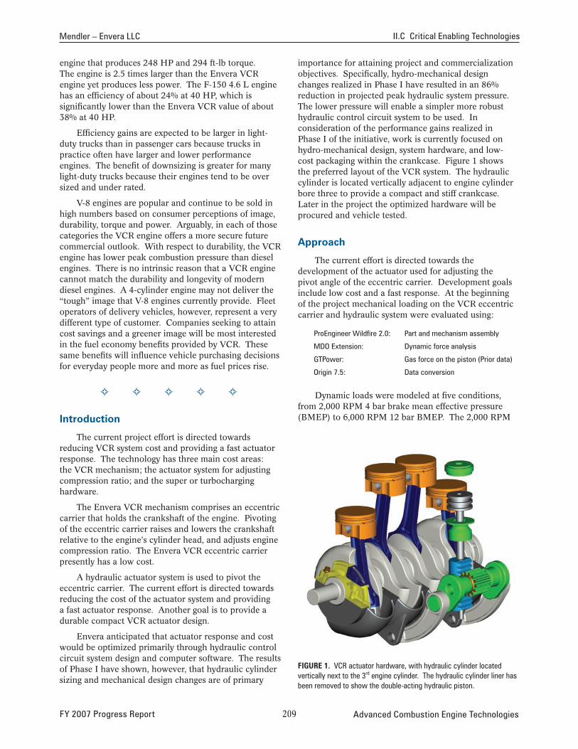
importance for attaining project and commercialization objectives. Specifically, hydro-mechanical design changes realized in Phase I have resulted in an 86% reduction in projected peak hydraulic system pressure. The lower pressure will enable a simpler more robust hydraulic control circuit system to be used. In consideration of the performance gains realized in Phase I of the initiative, work is currently focused on hydro-mechanical design, system hardware, and low-cost packaging within the crankcase. Figure 1 shows the preferred layout of the VCR system. The hydraulic cylinder is located vertically adjacent to engine cylinder bore three to provide a compact and stiff crankcase. Later in the project the optimized hardware will be procured and vehicle tested.
Approach
The current effort is directed towards the development of the actuator used for adjusting the pivot angle of the eccentric carrier. Development goals include low cost and a fast response. At the beginning of the project mechanical loading on the VCR eccentric carrier and hydraulic system were evaluated using:
ProEngineer Wildfire 2.0: Part and mechanism assembly
MDO Extension: Dynamic force analysis
GTPower: Gas force on the piston (Prior data)
Origin 7.5: Data conversion
Dynamic loads were modeled at five conditions, from 2,000 RPM 4 bar brake mean effective pressure (BMEP) to 6,000 RPM 12 bar BMEP. The 2,000 RPM
FiGure 1. VCR actuator hardware, with hydraulic cylinder located vertically next to the 3rd engine cylinder. The hydraulic cylinder liner has been removed to show the double-acting hydraulic piston.
FY 2007 Progress Report 20� Advanced Combustion Engine Technologies
II.C Critical Enabling Technologies Mendler – Envera LLC
12 bar BMEP condition causes the highest loading on the hydraulic system of about 2,250 psi. In Phase I of the project Envera pursued reducing the size of the hydraulic pressure spikes through system optimization. Through this effort peak hydraulic pressures have now been reduced to an estimated 314 PSI, an 86 percent reduction in peak pressure. This reduction in peak pressure is a huge improvement.
In consideration of the performance gains realized through geometry optimization, work is currently focused on hydro-mechanical design, system hardware, and low-cost packaging within the crankcase. Design work is presently being done in ProEngineer Wildfire 3.0. Finite element analysis will be preformed on highly loaded components after geometrical design requirements for the VCR have been established. Later in the project the optimized hardware will be procured and vehicle tested.
results
Hydraulic pressures in the actuator system were reduced by 86% through system optimization. The reduction in pressure significantly relaxes the demands that will be placed on the hydraulic system and enables cost to be reduced.
A test rig was designed and built for evaluating actuator response. Test results indicate that compression ratio can be reduced from 18:1 to 8.5:1 in ~0.35 seconds, and increased from 8.5:1 to 18:1 in ~0.70 seconds. On average 0.074 seconds is projected to elapse for each point increase in compression ratio.
conclusion
• During Phase I of the project hydraulic pressures in the actuator system were reduced by 86% through system optimization. The reduction in pressure will significantly relax the demands placed on the hydraulic actuator system.
• Down-sized gasoline VCR engines having optimized combustion can provide very large fuel economy benefits, and attain low tailpipe emission levels using proven catalytic converter technology. The VCR engine can also be operated on alternative fuels such as ethanol derived from switch grass or other biomass feedstock.
references
1. Automotive Engineering International (SAAB), pages 54-57, SAE, April 2001.
2. Automotive Engineer (SAAB), page 36, December 2000.
3. Gravel, R., and Mendler, C.(DOE, ENVERA): Variable Compression Ration (VCR) Engine, OAAT Accomplishments, www.eere.energy.gov/vehiclesandfuels/ pdfs/success/vcr3_29_01.pdf.
4. European Commission, Community Research, Variable Compression Ratio Technology for CO2 Reduction of Gasoline Engine Passenger Cars, europa.eu.int/comm/research/conferences/ 2002/pdf/presspacks/1-1-vcr_en.pdf.
5. Mendler, Charles (ENVERA): Variable Compression Ratio Engine, DOE FY 2003 Advanced Combustion Technologies Annual Report, US Department of Energy, 2003.
6. Mendler, Charles (ENVERA): Variable Compression Ratio Engine, DOE FY 2004 Advanced Combustion Technologies Annual Report, US Department of Energy, 2004.
7. Advanced Combustion and Emission Control Technical Roadmap for Light-Duty Powertrains, US Department of Energy, May 2006.
Advanced Combustion Engine Technologies 2�0 FY 2007 Progress Report
II.C.3 Development of Wide-Spectrum Voltammetric Sensors for Engine Exhaust NOx Measurement
Dr. Michael Vogt (Primary Contact), Mr. Alton Reich, Dr. Marcus Ashford, Ms. Amanda LardStreamline Automation, LLC3100 Fresh Way SW Huntsville, AL 35805
DOE Technology Development Manager: Roland Gravel
NETL Project Manager: Aaron Yocum
Subcontractor: University of Alabama, Tuscaloosa, AL
Objectives
• Fabricate and package voltammetric sensors to be suitable for engine exhaust testing.
• Operate the new sensors to provide nitrogen oxides (NOx) calibration data and results.
• Calibrate voltammetric sensor instrumentation with NOx results.
• Verify the operation of the instrumentation.
Accomplishments
• An all-new planar type voltammetric NOx gas sensor was designed, and all supplies for final fabrication were received.
• Existing monolithic cermet micro-arrays were modified with new solder-less leads for long-term high-temperature operation.
• A new rugged-ized stainless steel package was designed and prototyped.
• A new high-speed differencing voltammetry algorithm was engineered and employed for chemical characterization.
• Gas voltammetry was successfully applied to both commercial gas sensors (three) and to experimental gas micro-arrays (two).
• Unique electro-activity characterization was completed for NO, NO2, CO2, and NH3 gases, all at typical automotive emissions concentrations. Characterization included identifying repeatable dissociation potentials for each gas, and defining broader voltammetric signatures in both low O and2
high O backgrounds. 2
• Multiple gas analysis from a single sensor was demonstrated (NO, NO2, CO2, and NH3).
• Updates to the instrumentation design were completed, and a model for microcontroller deployment constructed.
• Collaboration relationships were established with Robert Bosch Corporation, to help construct the final sensors, and to evaluate the new NOx sensors for commercialization.
Future Directions
The immediate future work is to take the engineering lessons learned from the design of the new stainless steel package, and of high-temperature interconnects, and complete the final construction of the new planar-type NOx sensor. Robert Bosch Corporation has agreed to package these devices on a commercial assembly line, and provide the sensors for large-scale characterization in automotive test engine exhaust systems. During the next phase characterization, the differencing algorithm will be refined for real-time operation, and the identification and quantification portions of the signature processing will be integrated into that algorithm so that all processing is completed in real-time by an engine controller-type embedded computer.
G G G G G
introduction
The drive to develop a NOx sensor is promoted by environmental factors - NOx gases cause problems such as smog and acid rain so many countries have passed laws to limit NOx emissions. Past R&D concluded that materials and forms of existing NOx sensors were not their failure - it was the limitations of the phenomenon and measurement technique each employed. A practical automotive NOx sensor, free of these limitations, can be successfully developed based upon gas voltammetry as its core technology. This can be done by:
• Adapting the latest thick-film voltammetric gas sensor design to a form-factor suitable for deployment in an automotive exhaust system, and
• Aerforming proof-of-principal characterization and testing on operating spark-ignition and compression-ignition engines.
FY 2007 Progress Report 2�� Advanced Combustion Engine Technologies
II.C Critical Enabling Technologies Vogt – Streamline Automation, LLC
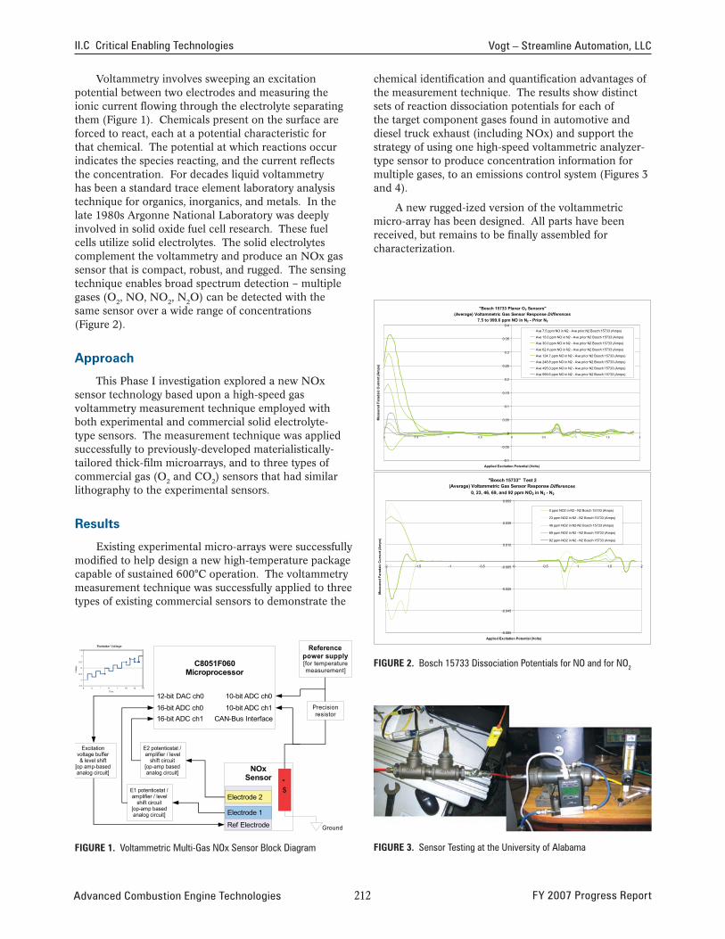
Voltammetry involves sweeping an excitation potential between two electrodes and measuring the ionic current flowing through the electrolyte separating them (Figure 1). Chemicals present on the surface are forced to react, each at a potential characteristic for that chemical. The potential at which reactions occur indicates the species reacting, and the current reflects the concentration. For decades liquid voltammetry has been a standard trace element laboratory analysis technique for organics, inorganics, and metals. In the late 1980s Argonne National Laboratory was deeply involved in solid oxide fuel cell research. These fuel cells utilize solid electrolytes. The solid electrolytes complement the voltammetry and produce an NOx gas sensor that is compact, robust, and rugged. The sensing technique enables broad spectrum detection – multiple gases (O2, NO, NO2, N2O) can be detected with the same sensor over a wide range of concentrations (Figure 2).
Approach
This Phase I investigation explored a new NOx sensor technology based upon a high-speed gas voltammetry measurement technique employed with both experimental and commercial solid electrolyte-type sensors. The measurement technique was applied successfully to previously-developed materialistically-tailored thick-film microarrays, and to three types of commercial gas (O2 and CO2) sensors that had similar lithography to the experimental sensors.
results
Existing experimental micro-arrays were successfully modified to help design a new high-temperature package capable of sustained 600°C operation. The voltammetry measurement technique was successfully applied to three types of existing commercial sensors to demonstrate the
" $
* +
FiGure 1. Voltammetric Multi-Gas NOx Sensor Block Diagram
chemical identification and quantification advantages of the measurement technique. The results show distinct sets of reaction dissociation potentials for each of the target component gases found in automotive and diesel truck exhaust (including NOx) and support the strategy of using one high-speed voltammetric analyzer-type sensor to produce concentration information for multiple gases, to an emissions control system (Figures 3 and 4).
A new rugged-ized version of the voltammetric micro-array has been designed. All parts have been received, but remains to be finally assembled for characterization.
"Bosch 15733 Planar O2 Sensors"
(Average) Voltammetric Gas Sensor Response Differences
7.5 to 999.6 ppm NO in N2 - Prior N2
-0.1
-0.05
0
0.05
0.1
0.15
0.2
0.25
0.3
0.35
0.4
-2 -1.5 -1 -0.5 0 0.5 1 1.5 2
Applied Excitation Potential (Volts)
Mea
sure
d Fa
rada
ic C
urre
nt (A
mps
)
Ave 7.5 ppm NO in N2 - Ave prior N2 Bosch 15733 (Amps)
Ave 15.0 ppm NO in N2 - Ave prior N2 Bosch 15733 (Amps)
Ave 30.0 ppm NO in N2 - Ave prior N2 Bosch 15733 (Amps)
Ave 62.4 ppm NO in N2 - Ave prior N2 Bosch 15733 (Amps)
Ave 124.7 ppm NO in N2 - Ave prior N2 Bosch 15733 (Amps)
Ave 248.8 ppm NO in N2 - Ave prior N2 Bosch 15733 (Amps)
Ave 495.0 ppm NO in N2 - Ave prior N2 Bosch 15733 (Amps)
Ave 999.6 ppm NO in N2 - Ave prior N2 Bosch 15733 (Amps)
"Bosch 15733" Test 2 (Average) Voltammetric Gas Sensor Response Differences
0, 23, 46, 69, and 92 ppm NO2 in N2 - N2
-0.065
-0.045
-0.025
-0.005
0.015
0.035
0.055
-2 -1.5 -1 -0.5 0 0.5 1 1.5 2
Applied Excitation Potential (Volts)
Mea
sure
d Fa
rada
ic C
urre
nt (A
mps
)
0 ppm NO2 in N2 - N2 Bosch 15733 (Amps)
23 ppm NO2 in N2 - N2 Bosch 15733 (Amps)
46 ppm NO2 in N2-N2 Bosch 15733 (Amps)
69 ppm NO2 in N2 - N2 Bosch 15733 (Amps)
92 ppm NO2 in N2 - N2 Bosch 15733 (Amps)
•FiGure 2. Bosch 15733 Dissociation Potentials for NO and for NO2
FiGure 3. Sensor Testing at the University of Alabama
Advanced Combustion Engine Technologies 2�2 FY 2007 Progress Report
Vogt – Streamline Automation, LLC II.C Critical Enabling Technologies
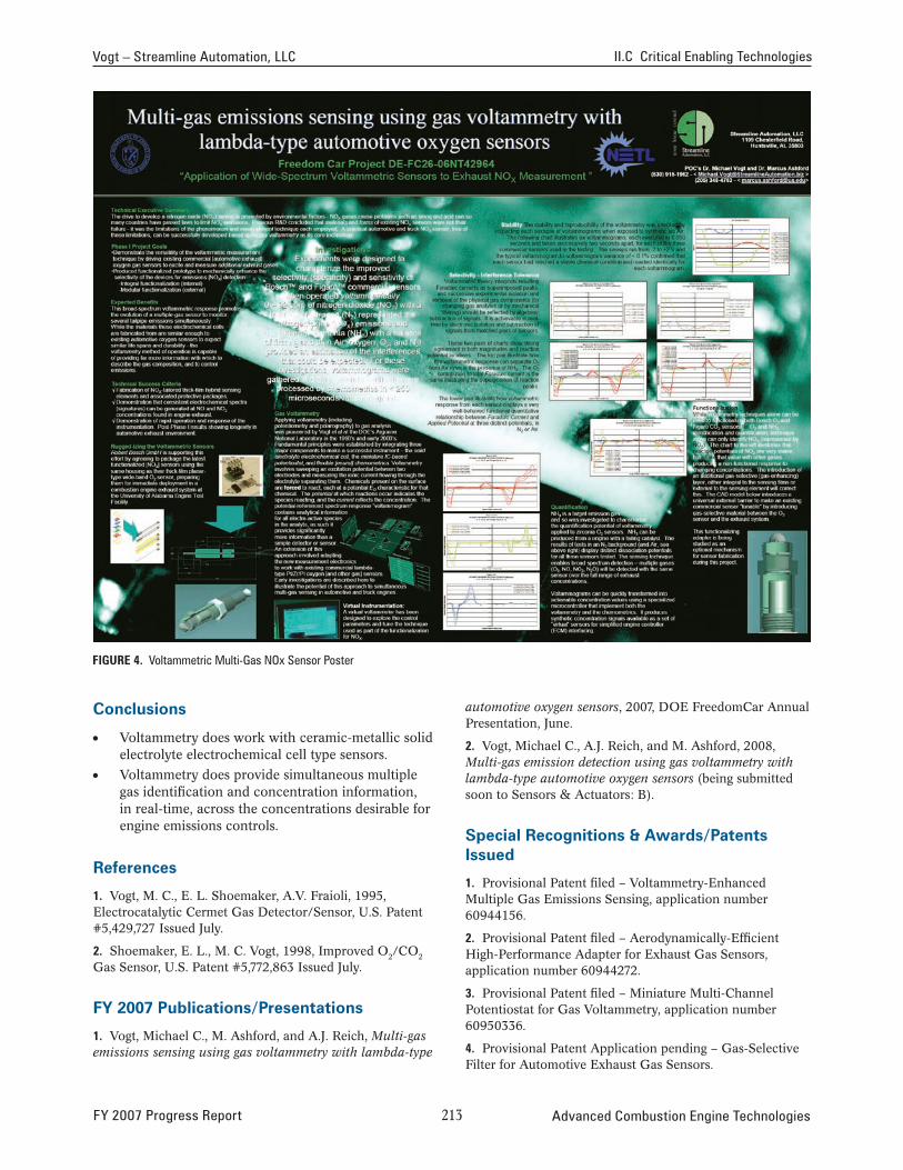
FiGure 4. Voltammetric Multi-Gas NOx Sensor Poster
conclusions
• Voltammetry does work with ceramic-metallic solid electrolyte electrochemical cell type sensors.
• Voltammetry does provide simultaneous multiple gas identification and concentration information, in real-time, across the concentrations desirable for engine emissions controls.
references
1. Vogt, M. C., E. L. Shoemaker, A.V. Fraioli, 1995, Electrocatalytic Cermet Gas Detector/Sensor, U.S. Patent #5,429,727 Issued July.
2. Shoemaker, E. L., M. C. Vogt, 1998, Improved O2/CO2
Gas Sensor, U.S. Patent #5,772,863 Issued July.
FY 2007 publications/presentations
1. Vogt, Michael C., M. Ashford, and A.J. Reich, Multi-gas emissions sensing using gas voltammetry with lambda-type
automotive oxygen sensors, 2007, DOE FreedomCar Annual Presentation, June.
2. Vogt, Michael C., A.J. Reich, and M. Ashford, 2008, Multi-gas emission detection using gas voltammetry with lambda-type automotive oxygen sensors (being submitted soon to Sensors & Actuators: B).
special recognitions & Awards/patents issued
1. Provisional Patent filed – Voltammetry-Enhanced Multiple Gas Emissions Sensing, application number 60944156.
2. Provisional Patent filed – Aerodynamically-Efficient High-Performance Adapter for Exhaust Gas Sensors, application number 60944272.
3. Provisional Patent filed – Miniature Multi-Channel Potentiostat for Gas Voltammetry, application number 60950336.
4. Provisional Patent Application pending – Gas-Selective Filter for Automotive Exhaust Gas Sensors.
FY 2007 Progress Report 2�� Advanced Combustion Engine Technologies
II.C4 Advanced Start of Combustion Sensor – Phase 1: Feasibility Demonstration
Chad Smutzer (Primary Contact), Robert Wilson TIAX LLC 15 Acorn Park Cambridge, MA 02140
DOE Technology Development Manager: Roland Gravel
NETL Project Manager: Samuel Taylor
Subcontractors: • Wayne State University, Detroit, MI • First tier automotive controls supplier
(asked to remain anonymous)
Objectives
• Develop an accelerometer-based start of combustion (SOC) sensor which provides adequate SOC event capture to control a homogeneous charge compression ignition (HCCI) engine in a feedback loop.
• Ensure that the developed sensor system will meet cost, durability, and software efficiency (speed) targets.
Accomplishments
• Two engines of same model line/different serial number installed to verify engine-to-engine repeatability of the SOC sensor system (a potential drawback of accelerometer-based systems).
• Developed an array of algorithms to translate the accelerometer signal into the desired SOC value.
• A library of data has been generated relating engine cylinder pressure to accelerometer events, and the algorithms are being evaluated on the accelerometer data.
Future Directions
• Testing will continue to generate further data at more speed and load points, and this data will be tested in the algorithms.
• Low-temperature combustion is planned to evaluate the sensor for HCCI engine operation (current data has been measured in diesel mode).
• The sensor package will be tried on the second engine setup to determine the engine-to-engine repeatability of the algorithms.
G G G G G
introduction
HCCI has elevated the need for SOC sensors. HCCI engines have been the exciting focus of engine research recently, primarily because HCCI offers higher thermal efficiency than the conventional spark ignition engines and significantly lower NOx and soot emissions than conventional compression ignition engines, and could be fuel neutral. HCCI has the potential to unify all the internal combustion engine technologies to achieve the high-efficiency low-emission goal. However, these advantages do not come easy. It is well known now that the problems encountered with HCCI combustion center on the difficulty of controlling the start of combustion. The emergence of a durable and effective SOC sensor will solve what is arguably the most critical challenge to the viability of HCCI engine platforms. The SOC sensor could be an enabler for a new breed of engines saving 15-20% of petroleum used in transportation, while meeting or exceeding 2010 emission targets.
Approach
The design phase of the project was initiated first, during which the algorithms are being conceptualized and the sensor configuration is being designed. In parallel to the conceptualization of the algorithms, the hardware test setups are being completed. To test the engine-to-engine repeatability of the sensor signals, two engines of different serial numbers but the same model were set up. Once the algorithms are conceptualized and implemented in software, the data from the engine set-ups will be fed into the algorithms to see if they successfully and robustly determine SOC. This process is designed to require some iteration, but following the tasks in the order shown will minimize the iterations and allow for the team to compensate should there be any surprises. Throughout all of these tasks, the team has guided the SOC sensor design effort toward what will be required for commercialization. The work flow was carefully designed to ensure the risk is minimal and that technical success probability is high, and iterations are included to counter any setbacks that may be encountered.
Advanced Combustion Engine Technologies 2�� FY 2007 Progress Report
Smutzer – TIAX LLC II.C Critical Enabling Technologies
results
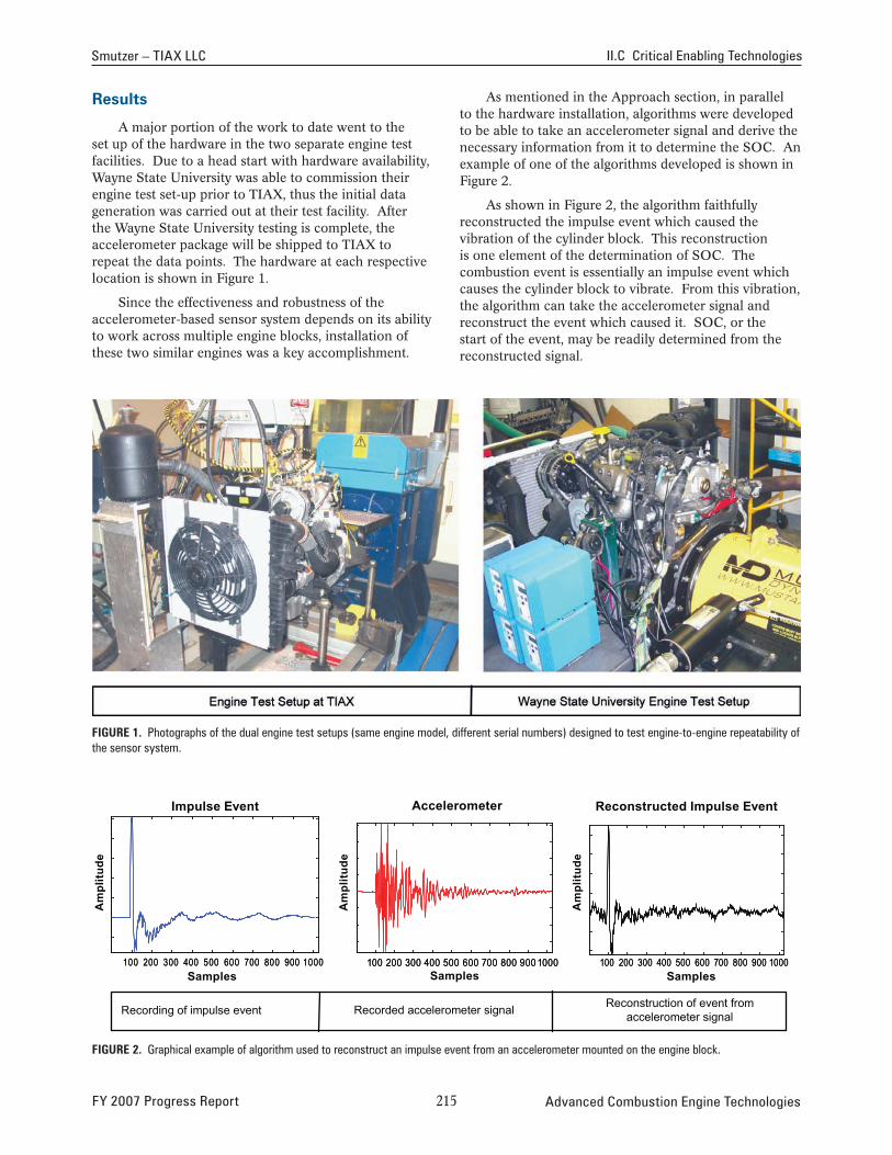
A major portion of the work to date went to the set up of the hardware in the two separate engine test facilities. Due to a head start with hardware availability, Wayne State University was able to commission their engine test set-up prior to TIAX, thus the initial data generation was carried out at their test facility. After the Wayne State University testing is complete, the accelerometer package will be shipped to TIAX to repeat the data points. The hardware at each respective location is shown in Figure 1.
Since the effectiveness and robustness of the accelerometer-based sensor system depends on its ability to work across multiple engine blocks, installation of these two similar engines was a key accomplishment.
As mentioned in the Approach section, in parallel to the hardware installation, algorithms were developed to be able to take an accelerometer signal and derive the necessary information from it to determine the SOC. An example of one of the algorithms developed is shown in Figure 2.
As shown in Figure 2, the algorithm faithfully reconstructed the impulse event which caused the vibration of the cylinder block. This reconstruction is one element of the determination of SOC. The combustion event is essentially an impulse event which causes the cylinder block to vibrate. From this vibration, the algorithm can take the accelerometer signal and reconstruct the event which caused it. SOC, or the start of the event, may be readily determined from the reconstructed signal.
FiGure 1. Photographs of the dual engine test setups (same engine model, different serial numbers) designed to test engine-to-engine repeatability of the sensor system.
Impulse Event Accelerometer Reconstructed Impulse Event
Am
plitu
de
Am
plitu
de
Am
plitu
de
100 200 300 400 500 600 700 800 900 1000 100 200 300 400 500 600 700 800 900 1000 100 200 300 400 500 600 700 800 900 1000100 200 300 400 500 600 700 800 900 1000 100 200 300 400 500 600 700 800 900 1000 100 200 300 400 500 600 700 800 900 1000Samples Samples Samples
Reconstruction of event from accelerometer signalRecorded accelerometer signalRecording of impulse event
FiGure 2. Graphical example of algorithm used to reconstruct an impulse event from an accelerometer mounted on the engine block.
FY 2007 Progress Report 2�� Advanced Combustion Engine Technologies
II.C Critical Enabling Technologies Smutzer – TIAX LLC
0.03 0.04 0.05 0.06 0.07 0.08 0.09 0.1
0.03 0.04 0.05 0.06 0.07 0.08 0.09 0.1
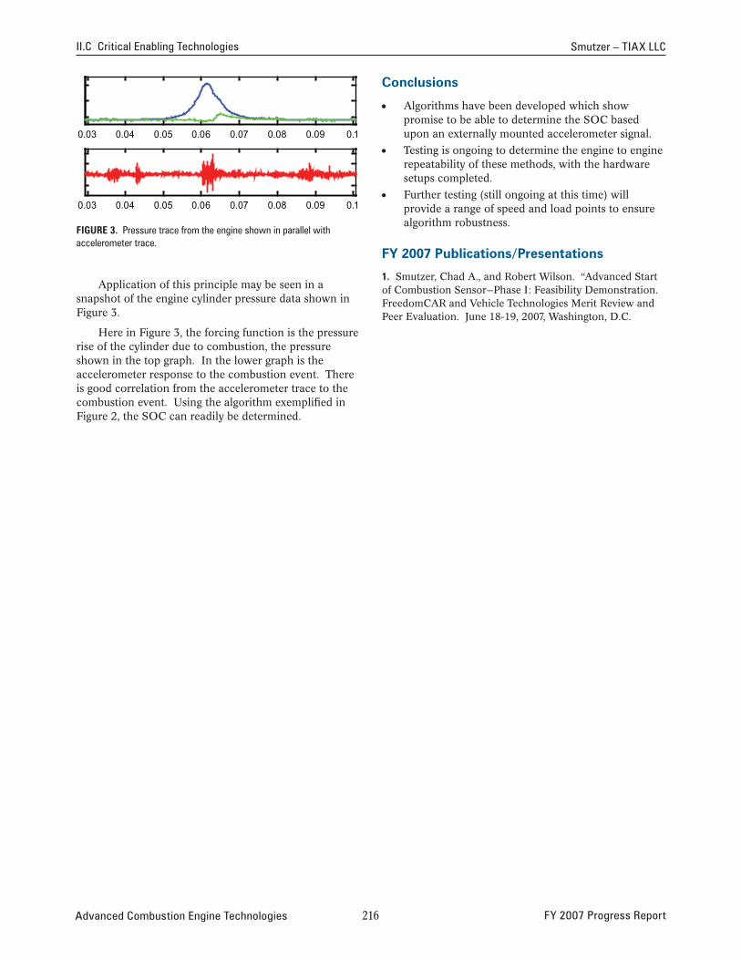
FiGure 3. Pressure trace from the engine shown in parallel with accelerometer trace.
Application of this principle may be seen in a snapshot of the engine cylinder pressure data shown in Figure 3.
Here in Figure 3, the forcing function is the pressure rise of the cylinder due to combustion, the pressure shown in the top graph. In the lower graph is the accelerometer response to the combustion event. There is good correlation from the accelerometer trace to the combustion event. Using the algorithm exemplified in Figure 2, the SOC can readily be determined.
conclusions
• Algorithms have been developed which show promise to be able to determine the SOC based upon an externally mounted accelerometer signal.
• Testing is ongoing to determine the engine to engine repeatability of these methods, with the hardware setups completed.
• Further testing (still ongoing at this time) will provide a range of speed and load points to ensure algorithm robustness.
FY 2007 publications/presentations
1. Smutzer, Chad A., and Robert Wilson. “Advanced Start of Combustion Sensor—Phase I: Feasibility Demonstration. FreedomCAR and Vehicle Technologies Merit Review and Peer Evaluation. June 18-19, 2007, Washington, D.C.
Advanced Combustion Engine Technologies 2�� FY 2007 Progress Report
II.C.5 The Development of a Robust Accelerometer-Based Start of Combustion Sensing System
David Mumford (Primary Contact), Jim Huang Westport Power, Inc. 1691 West 75th Avenue Vancouver, BC V6P 6P2 Canada
DOE Technology Development Manager: Roland Gravel
NETL Project Manager: Jason Conley
Objectives
Phase 1 (October 2006 to July 2007):
• Identify the critical parameters that influence engine-to-engine variation in the accelerometer sensor signal.
• Develop engine-to-engine compensation techniques, using data collected from two engine configurations.
• Verify on paper that the robustness compensation techniques will meet performance requirements.
Phase 2 (August 2007 to July 2008):
• Develop a charge amplifier for use with knock sensors, if required.
• Develop a sensor characterization method, and select the best sensor for the application based on sensor characterization tests.
• Further develop robustness compensation techniques to include the impact of sensor-to-sensor variations, using additional data collected from an engine with different sensor configurations.
• Verify on paper that the robustness compensation techniques will meet performance requirements.
Accomplishments
• Confirmed that the vertical acceleration of the main bearing caps (MBC) has the best correlation with the start of combustion timing.
• Developed an algorithm to obtain the timing for the start of combustion using accelerometers.
• The targeted start of combustion (SOC) error standard deviation is 0.5 crank angle degrees (CAD). The current results have largely exceeded this target for all the testing modes. The averaged engine-to-engine variation over all modes is 0.32 CAD with 98.9% confidence level.
Future Directions:
• Study sensor-to-sensor variation on the two Cummins ISB engines.
• Study the effectiveness of the current compensation methods in dealing with sensor-to-sensor variation.
• Investigate a charge amplifier for gain compensation.
• Further improve robustness using signals from non-adjacent bearing caps (higher degree of redundancy).
G G G G G
introduction
The development of modern combustion systems increasingly relies on detailed knowledge of the combustion event. As the limits of combustion are approached, tight control of combustion leads to improved emissions and higher efficiencies, while retaining and even improving engine reliability and durability.
While developing a novel combustion technology, Westport found that there was no reliable cost-effective technology to monitor the combustion event. As a result, Westport began developing a solution based on commercially available knock sensors. Numerous other forms of combustion (high exhaust gas recirculation systems, homogeneous charge direct injection, etc) may also benefit from this work. Westport has previously proven this method on two different large compression ignition gas engines. The objective of the current work is to improve robustness of this technology; particularly, to identify and reduce the engine-to-engine and sensor-to-sensor variations.
Approach
The experimental study was carried out on two Cummins ISB 5.9L HPCR diesel engines. Accelerometer (knock sensor) data were collected for six of the 13 European Stationary Cycle (ESC) testing modes, which cover a wide range of engine load and speed conditions. Corresponding in-cylinder pressure data was also collected to determine the actual SOC and other combustion parameters.
This data was analyzed to develop a robust algorithm to reliably predict the SOC timing across the different engine modes. Initially this was assessed with two different engines to compare engine-to-engine
FY 2007 Progress Report 2�7 Advanced Combustion Engine Technologies
II.C Critical Enabling Technologies Mumford – Westport Power, Inc
variation with the sensors. Current work is now focused on comparing different sensors and investigating the effect of charge amplification.
results
The two Cummins engines were fully commissioned and baseline tests were conducted at the rated power and torque. A set of six Kistler 6607C1 water-cooled pressure transducers were used to measure the in-cylinder pressures. A Cummins CELL high speed data acquisition system was used to collect the pressure and knock sensor data generated during the engine testing.
For the current study, the accelerometers are mounted directly to the main bearing caps. Finite element analyses of the cap showed that the change in maximum stress due to drilling either a single hole or two holes into the cap was within the acceptable range with the desired safety factor.
Knock sensor and in-cylinder pressure data from the two engines were collected at six modes selected from the 13 ESC modes. For each mode, tests were conducted at nominal, advanced and retarded injection timing (Table 1). Motoring data were also collected for each mode at the nominal timing by intermittently cutting off the injection for a selected cylinder. A repeatability study was conducted on engine #1 to examine the effect on the knock sensor signal of remounting the sensor. Test points were also repeated for engine #2, except for remounting.
Data were also collected at all modes with a Ditran302382 tri-axial research-grade accelerometer mounted on selected bearing caps. The data were used to compare with those from the knock sensors to improve the understanding of the sensor performance.
Table 1. Engine Test Modes
engines show predominantly low-frequency signals. Analysis of the high-frequency signal established the reproducibility of a characteristic frequency between the two ISB engines. The high frequency signal and the low frequency signal were adopted as independent measures for determining SOC.
There are four main steps to the processing algorithm:
1. Pre-process the raw accelerometer data
2. Reconstruct the heat release rate
3. Extract SOC information from the accelerometer signals
4. Select the SOC timing with the highest confidence level
The rate of heat release curve in the current study has a unique double-peak feature. The complex shape of this curve together with the multiple-peak input signal from the knock sensor makes a general transfer function difficult to achieve. In particular, it is difficult to separate the accelerometer signal corresponding to the high-frequency components in the heat release rate from the noise.
The phase shift among different ignition timings was observed in the high-frequency, low-frequency and reconstructed data. A global and a local method were used to obtain the phase shift of SOC from the calibration signal. Both methods can provide an independent SOC estimate, and the results were crosschecked with each other to improve the reliability.
Timing swings were used at advanced, nominal, and slow combustion rates to test SOC detection at the widest expected range of heat release rates. The scatter
Cylinder4,Bearing Cap5 1.5
Motoring Firing
esC mode
%load Torque (nm)
rPm Power (bhP)
start of injection1
5 50 305 1885 109 a, n, r
6 75 457.5 1885 164 a, n, r
8 100 610 2292 266 a, n, r
9 25 152.5 2292 67 a, n, r
12 75 457.5 2698 235 a, n, r
13 50 305 2698 157 a, n, r 1 Nominal (n), advanced (a) and retarded (r) timing HR
RV
Sens
or 1
0.5
0
-0.5 -30 -20 -10 0 10 20 30 40
Crank Angle [Degree] 0.08
0.06
0.04
0.02
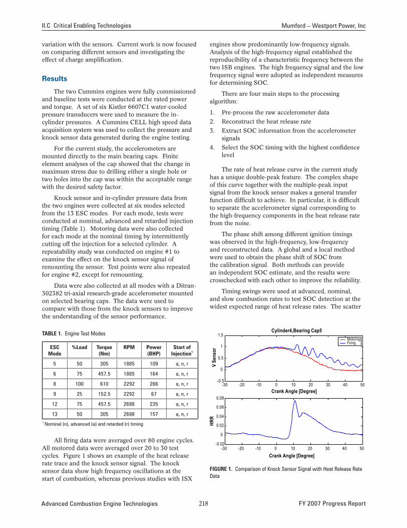
0 All firing data were averaged over 80 engine cycles.
All motored data were averaged over 20 to 30 test cycles. Figure 1 shows an example of the heat release rate trace and the knock sensor signal. The knock sensor data show high frequency oscillations at the start of combustion, whereas previous studies with ISX
Advanced Combustion Engine Technologies
-0.02 -30 -20 -10 0 10 20 30 40 50
Crank Angle [Degree]
Figure 1. Comparison of Knock Sensor Signal with Heat Release Rate Data
2�� FY 2007 Progress Report
50
Mumford – Westport Power, Inc II.C Critical Enabling Technologies
of data tends to increase with delayed ignition. The signal to noise ratio was also found to be relatively low at high speed and low load conditions.
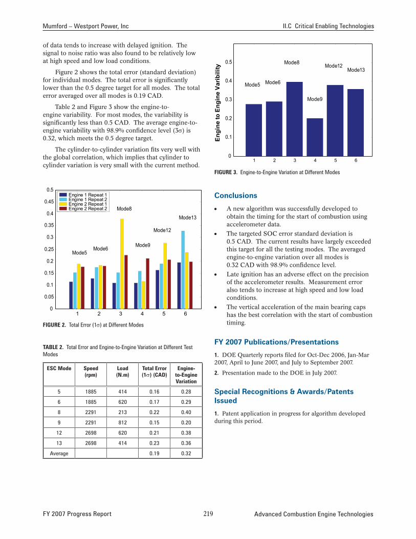
Figure 2 shows the total error (standard deviation) for individual modes. The total error is significantly lower than the 0.5 degree target for all modes. The total error averaged over all modes is 0.19 CAD.
Table 2 and Figure 3 show the engine-toengine variability. For most modes, the variability is significantly less than 0.5 CAD. The average engine-toengine variability with 98.9% confidence level (3σ) is 0.32, which meets the 0.5 degree target.
The cylinder-to-cylinder variation fits very well with the global correlation, which implies that cylinder to cylinder variation is very small with the current method.
0.5
0.45
0.4
0.35
0.3
0.25
0.2
0.15
0.1
0.05
0
Mode5 Mode6
Mode8
Mode9
Mode12
Mode13
Engine 1 Repeat 1Engine 1 Repeat 2Engine 2 Repeat 1Engine 2 Repeat 2
1 2 3 4 5 6
FiGure 2. Total Error (1σ) at Different Modes
Table 2. Total Error and Engine-to-Engine Variation at Different Test Modes
esC mode speed (rpm)
load (n.m)
Total error (1σ) (Cad)
engine-to-engine Variation
5 1885 414 0.16 0.28
6 1885 620 0.17 0.29
8 2291 213 0.22 0.40
9 2291 812 0.15 0.20
12 2698 620 0.21 0.38
13 2698 414 0.23 0.36
Average 0.19 0.32
Engi
ne to
Eng
ine
Varib
ility
0.5
0.4
0.3
0.2
0.1
0
Mode5 Mode6
Mode8
Mode9
Mode12 Mode13
1 2 3 4 5 6
FiGure 3. Engine-to-Engine Variation at Different Modes
conclusions
• A new algorithm was successfully developed to obtain the timing for the start of combustion using accelerometer data.
• The targeted SOC error standard deviation is 0.5 CAD. The current results have largely exceeded this target for all the testing modes. The averaged engine-to-engine variation over all modes is 0.32 CAD with 98.9% confidence level.
• Late ignition has an adverse effect on the precision of the accelerometer results. Measurement error also tends to increase at high speed and low load conditions.
• The vertical acceleration of the main bearing caps has the best correlation with the start of combustion timing.
FY 2007 publications/presentations
1. DOE Quarterly reports filed for Oct-Dec 2006, Jan-Mar 2007, April to June 2007, and July to September 2007.
2. Presentation made to the DOE in July 2007.
special recognitions & Awards/patents issued
1. Patent application in progress for algorithm developed during this period.
FY 2007 Progress Report 2�� Advanced Combustion Engine Technologies
II.C.6 Electrically Coupled Exhaust Energy Recovery System Using a Series Power Turbine Approach
Carl T. Vuk John Deere Product Engineering Center P.O. Box 8000 Waterloo, IA 50704
DOE Technology Development Manager: John Fairbanks
NETL Project Manager: Ralph Nine
Subcontractor:International Truck, Fort Wayne, IN
Objective
The overall objective of this project is to demonstrate the technical benefits of electrically-coupled turbo compounding. Specific objectives for 2007 included:
• Optimize system performance characteristics over operating envelope.
• Develop design of production viable hardware components.
• Demonstrate performance characteristics through vehicle testing.
Accomplishments
The overall project goal of a 10% improvement in fuel economy was successfully demonstrated over most of the operating speed range. Additional potential performance improvement was characterized. Technology was developed to exploit the flexibility of the electrical coupling to optimize system performance as a function of both engine speed and load.
Second generation components were designed. A smaller, higher performing turbo generator has been designed that exhibits considerable simplification. A series turbocharger system that provides improved performance and range was also successfully designed and modeled.
The Deere 8530 turbo compounded tractor was evaluated on the test track after developing suitable controls to handle normal vehicle transients. The International truck was also updated with a complete turbo compounding system.
Future Directions
Vehicle testing to better define actual operating fuel savings is the next step in the project. Emphasis will be primarily on the truck, since this application can have the greatest impact on national fuel usage.
Second generation hardware sized to match Tier 4 emissions regulations with interstage after-treatment has been designed. This hardware needs to be built and tested at Tier 4 conditions.
A systems approach to optimization has proven valuable in early work. Second generation hardware will have greater flexibility and hence more potential for optimization. Additional work is needed here for specific applications as well as broadening the scope of applications using common base hardware. Series turbochargers provide additional flexibility, but matching strategies with as much common hardware is desirable.
Commercialization potential needs to be defined. More detailed cost analysis and projections are required. Volume projections will be important here, so knowing the nature of the benefits over a range of applications will be required. With hybrid technology catching on in trucks, the economic justification becomes much easier.
G G G G G
introduction
The objective of this project is to characterize fuel economy, power growth, and emissions benefits of electrically-coupled turbo compounding, an intelligent waste exhaust heat recovery technology. The rapid adoption of hybrid technology into trucks has the effect of promoting the technology in two ways. First, the widespread application of power electronics in heavy-duty applications will have a favorable impact on component costs required for turbo compounding. The second impact is related to the synergism of hybridization and electric turbo compounding. Hybrid vehicles bring considerable infrastructure that is required for turbo compounding. This effectively lowers the incremental cost of turbo compounding. Hybrid trucks have demonstrated significant fuel economy advantages in stop-and-go driving common to busses, delivery vehicles, and refuse haulers. The advantages in line haul applications are less clear. This is where electric turbo compounding is at its best. The combination of hybridization and turbo compounding is truly synergistic and together both technologies will advance.
Advanced Combustion Engine Technologies 220 FY 2007 Progress Report
Vuk – John Deere Product Engineering Center II.C Critical Enabling Technologies
Changes during the past year relative to CO2
emissions have the potential to drive the technology. The Supreme Court’s decision characterizing CO2 as a regulated emission is significant. The proposal to increase Corporate Average Fuel Economy (CAFE) mileage targets and to also cover heavy-duty and off-road vehicles are also significant new drivers. Increasing fuel economy has direct benefits in lower operating cost, and in conservation, but now also impact CO2 in direct proportion to the fuel economy improvement. Multiple technologies will no doubt be required to fully address these issues, but turbo compounding can clearly play an important role. This is new in 2007, and will help propel this technology into commercial vehicles.
Approach
Extensive dyno testing was completed in an effort to match turbo machinery hardware and optimize system performance over the operating envelope. The impact of Tier 4 after-treatment exhaust pressure restrictions were modeled and tested with several different architectures. Dyno testing was also used to help define transient system behavior prior to vehicle testing. Initial tractor testing was also completed on the test track to optimize dynamic system behavior and transient response characteristics.
Based on encouraging performance improvements, next generation system hardware architecture was defined, and design work initiated.
System hardware for the truck application was designed, built, and installed in an International 8600 truck. The truck will be used to determine the fuel economy benefits over a range of standard driving cycles.
results
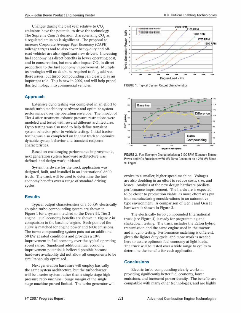
Typical output characteristics of a 50 kW electrically coupled turbo compounding system are shown in Figure 1 for a system matched to the Deere 9L Tier 3 engine. Fuel economy benefits are shown in Figure 2 in comparison to the baseline engine. Each point of the curve is matched for engine power and NOx emissions. The turbo compounding system puts out an additional 50 kW at rated conditions and provides a 10% improvement in fuel economy over the typical operating speed range. Significant additional fuel economy improvement potential is believed possible because hardware availability did not allow all components to be simultaneously optimized.
Next generation hardware will employ basically the same system architecture, but the turbocharger will be a series system rather than a single stage high pressure ratio machine. Surge margin of the single stage machine proved limited. The turbo generator will
FiGure 1. Typical System Output Characteristics
FiGure 2. Fuel Economy Characteristics at 2100 RPM (Constant Engine Power and NOx Emissions w/50 kW Turbo Generator on a 280 kW Rated 9L Engine)
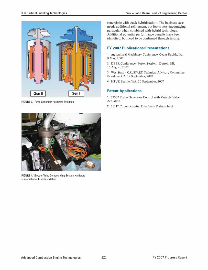
evolve to a smaller, higher speed machine. Voltages are also doubling in an effort to reduce costs, size, and losses. Analysis of the new design hardware predicts performance improvement. The hardware is expected to be closer to production viable, as more effort was put into manufacturing considerations in an automotive type environment. A comparison of Gen I and Gen II hardware is shown in Figure 3.
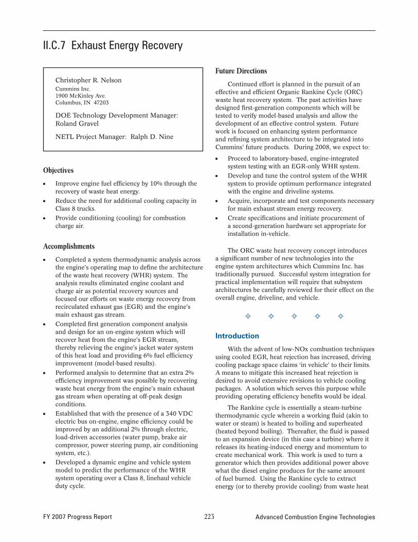
The electrically turbo compounded International truck (see Figure 4) is ready for programming and shakedown testing. The truck includes the Eaton hybrid transmission and the same engine used in the tractor and in dyno testing. Performance matching is different, given the lighter duty cycle, and more work is needed here to assure optimum fuel economy at light loads. The truck will be tested over a wide range to cycles to determine the benefits for each application.
conclusions
Electric turbo compounding clearly works in providing significantly better fuel economy, lower emissions, and increased power density. The benefits are compatible with many other technologies, and are highly
FY 2007 Progress Report 22� Advanced Combustion Engine Technologies
II.C Critical Enabling Technologies Vuk – John Deere Product Engineering Center
FiGure 3. Turbo Generator Hardware Evolution
FiGure 4. Electric Turbo Compounding System Hardware – International Truck Installation
synergistic with truck hybridization. The business case needs additional refinement, but looks very encouraging, particular when combined with hybrid technology. Additional potential performance benefits have been identified, but need to be confirmed through testing.
FY 2007 publications/presentations
1. Agricultural Machinery Conference, Cedar Rapids, IA, 9 May, 2007.
2. DEER Conference (Poster Session), Detroit, MI, 15 August, 2007.
3. WestStart – CALSTART, Technical Advisory Committee, Pasadena, CA, 12 September, 2007.
4. HTUF, Seattle, WA, 20 September, 2007.
patent Applications
1. 17307 Turbo Generator Control with Variable Valve Actuation.
2. 18117 Circumferential Dual-Vane Turbine Inlet.
Advanced Combustion Engine Technologies 222 FY 2007 Progress Report
II.C.7 Exhaust Energy Recovery
Christopher R. Nelson Cummins Inc. 1900 McKinley Ave. Columbus, IN 47203
DOE Technology Development Manager: Roland Gravel
NETL Project Manager: Ralph D. Nine
Objectives
• Improve engine fuel efficiency by 10% through the recovery of waste heat energy.
• Reduce the need for additional cooling capacity in Class 8 trucks.
• Provide conditioning (cooling) for combustion charge air.
Accomplishments
• Completed a system thermodynamic analysis across the engine’s operating map to define the architecture of the waste heat recovery (WHR) system. The analysis results eliminated engine coolant and charge air as potential recovery sources and focused our efforts on waste energy recovery from recirculated exhaust gas (EGR) and the engine’s main exhaust gas stream.
• Completed first generation component analysis and design for an on-engine system which will recover heat from the engine’s EGR stream, thereby relieving the engine’s jacket water system of this heat load and providing 6% fuel effi ciency improvement (model-based results).
• Performed analysis to determine that an extra 2% efficiency improvement was possible by recovering waste heat energy from the engine’s main exhaust gas stream when operating at off-peak design conditions.
• Established that with the presence of a 340 VDC electric bus on-engine, engine efficiency could be improved by an additional 2% through electric, load-driven accessories (water pump, brake air compressor, power steering pump, air conditioning system, etc.).
• Developed a dynamic engine and vehicle system model to predict the performance of the WHR system operating over a Class 8, linehaul vehicle duty cycle.
Future Directions
Continued effort is planned in the pursuit of an effective and efficient Organic Rankine Cycle (ORC) waste heat recovery system. The past activities have designed first-generation components which will be tested to verify model-based analysis and allow the development of an effective control system. Future work is focused on enhancing system performance and refining system architecture to be integrated into Cummins’ future products. During 2008, we expect to:
• Proceed to laboratory-based, engine-integrated system testing with an EGR-only WHR system.
• Develop and tune the control system of the WHR system to provide optimum performance integrated with the engine and driveline systems.
• Acquire, incorporate and test components necessary for main exhaust stream energy recovery.
• Create specifications and initiate procurement of a second-generation hardware set appropriate for installation in-vehicle.
The ORC waste heat recovery concept introduces a significant number of new technologies into the engine system architectures which Cummins Inc. has traditionally pursued. Successful system integration for practical implementation will require that subsystem architectures be carefully reviewed for their effect on the overall engine, driveline, and vehicle.
� � � � �
Introduction
With the advent of low-NOx combustion techniques using cooled EGR, heat rejection has increased, driving cooling package space claims ‘in vehicle’ to their limits. A means to mitigate this increased heat rejection is desired to avoid extensive revisions to vehicle cooling packages. A solution which serves this purpose while providing operating effi ciency benefits would be ideal.
The Rankine cycle is essentially a steam-turbine thermodynamic cycle wherein a working fl uid (akin to water or steam) is heated to boiling and superheated (heated beyond boiling). Thereafter, the fluid is passed to an expansion device (in this case a turbine) where it releases its heating-induced energy and momentum to create mechanical work. This work is used to turn a generator which then provides additional power above what the diesel engine produces for the same amount of fuel burned. Using the Rankine cycle to extract energy (or to thereby provide cooling) from waste heat
FY 2007 Progress Report 223 Advanced Combustion Engine Technologies
II.C Critical Enabling Technologies Nelson – Cummins Inc.
streams serves to reduce the amount of heat which must be rejected while simultaneously providing extra power. Reducing heat rejection and minimizing cooling package size serves to provide vehicle manufacturers with continued opportunities to minimize vehicle frontal area, reducing aerodynamic drag, and improving fuel economy.
The Exhaust Energy Recovery project at Cummins Inc. was initiated by experiments conducted under the Heavy Duty Truck Engine project. During this testing, a Rankine cycle was employed in support of that project’s high engine efficiency demonstration. In the current work, Rankine cycle heat recovery is being focused on the heavy duty diesel engine’s EGR and main exhaust gas streams. Recovery of EGR heat will relieve the engine’s cooling system of a significant portion of this waste heat energy. The EGR energy recovery system must necessarily be designed to capture the peak heat load from this waste energy stream. During off-peak operation, when excess heat rejection capacity exists in the EGR energy recovery system, additional energy may be recovered from the engine’s main exhaust gas stream which will keep the Rankine Cycle system operating at its peak capability. This technique will maximize the benefit of the energy recovery system.
Approach
Cummins’ approach to the project objectives emphasizes analysis-led-design in nearly all aspects of the research. An emphasis is placed on modeling and simulation results to lead the way into feasible solutions.
With the advent of cooled EGR-based combustion technology, the need to provide an effective cooling system for combustion charge conditioning has become vital. The additional cooling required for EGR and fresh charge air to thereby achieve low intake manifold temperatures (in pursuit of clean combustion) has driven an increase in vehicle cooling system performance.
A Rankine cycle extracting heat energy from the engine’s EGR stream reduces the heat load on the engine system cooling package and simultaneously provides extra power from the engine system. The cycle’s turbine-driven electric generator provides power which may be used for a number of different on-vehicle applications including:
• Traditional alternator load (alternator may be removed)
• Supplemental power to engine output (through the use of a driveline-coupled motor)
• More efficient parasitics in the form of coolant pumps, air compressors, etc.
To efficiently accommodate power from the Rankine cycle generator and to minimize its size, higher voltage
than what is traditionally used on heavy-duty vehicles (12 VDC) is required. The recommended voltage level of approximately 340 VDC creates opportunities to use efficient and cost-effective power electronics developed for use in other industries (rectifiers, power conditioners, motor drives, etc.) and components and techniques common with hybrid electric vehicles. High-speed, permanent-magnet or switched-reluctance generators and motors are also compatible with this higher-voltage environment. This compatibility leads to further applications of these devices with subsequent efficiency benefits to the engine and vehicle.
results
Research has been focused on identifying the most effective techniques and tools for Rankine cycle application to a heavy-duty diesel engine installed in a Class 8 tractor.
Simulation Analysis
A simple Recuperated Rankine Cycle is schematically presented in Figure 1. Saturated liquid working fluid (blue) comes from the system condenser and first passes through a recuperator which transfers energy left over after turbine energy extraction. The fluid then passes to the engine heat exchangers (charge air cooler and EGR cooler) where it reaches a superheated state. The superheated vapor is then passed through the turbine to generate electricity. The fluid then passes through the recuperator and then the condenser.
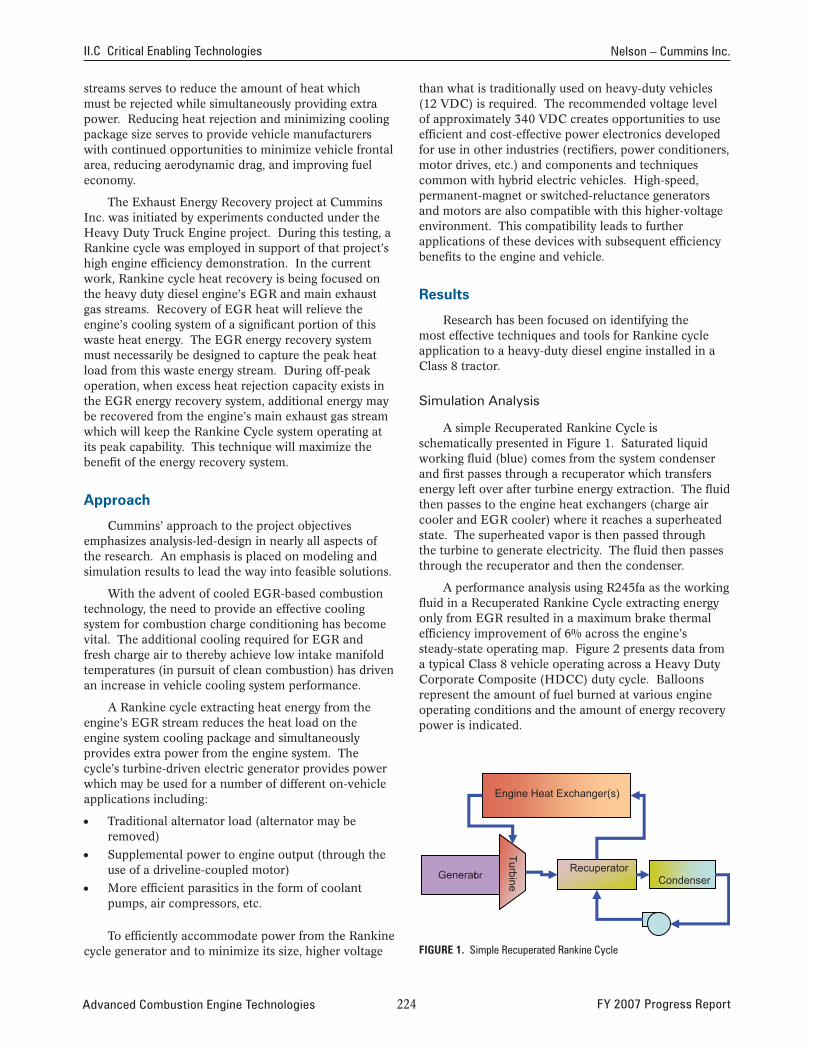
A performance analysis using R245fa as the working fluid in a Recuperated Rankine Cycle extracting energy only from EGR resulted in a maximum brake thermal efficiency improvement of 6% across the engine’s steady-state operating map. Figure 2 presents data from a typical Class 8 vehicle operating across a Heavy Duty Corporate Composite (HDCC) duty cycle. Balloons represent the amount of fuel burned at various engine operating conditions and the amount of energy recovery power is indicated.
Recuperator Condenser
Turbine
Generator
Engine Heat Exchanger(s)
FiGure 1. Simple Recuperated Rankine Cycle
Advanced Combustion Engine Technologies 22� FY 2007 Progress Report
13
0.1611.4
8.7
29.3
6.7
25.1
0.31
2.30.31
Percent Fuel Used
B50
B63
B75
A100C100
B100
A10016 hp
B5017.2 hp
B6318.2 hp
B7519.6 hp
B10021.3 hp
C10020.2 hp
Waste Heat RecoveryPower
Percent Fuel Used
B50
B63
B75
A100C100
B100
Turbine-Generator
filter/dryersight-glass
feedpump
Recuperator
Preheater/BoilerSuperheater
-
-
--
Nelson – Cummins Inc. II.C Critical Enabling Technologies
International Prostar on HDCC Cycle in VMS (13-Mode) 500
450
400
350
300
250
200
150
100
Waste Heat Recovery Power
50
0 1000 1100 1200 1300 1400 1500 1600 1700 1800 1900 2000
13
0.16 11.4
8.7 29.3
B50
B75
6.7
25.1
0.31
2.30.31
A100 16 hp
17.2 hp
B63 18.2 hp
19.6 hp
B100 21.3 hp
C100 20.2 hp
Engine Speed, RPM
FiGure 2. Additional Power Provided by the Cummins WHR system Across an Engine Operating Map
The additional recovered power is provided to the engine as high voltage (340 VDC) electricity which may be used to power engine and vehicle parasitics or to supplement the engine’s brake power output through a driveline motor (incorporated into the engine’s flywheel or elsewhere).
Superheater Preheater/Boiler
Recuperator
Hardware Design
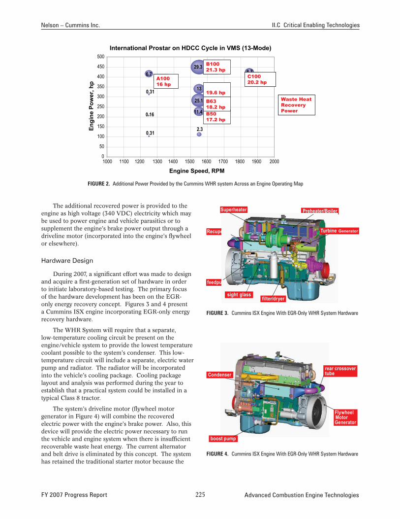
During 2007, a significant effort was made to design and acquire a first-generation set of hardware in order to initiate laboratory-based testing. The primary focus of the hardware development has been on the EGR-only energy recovery concept. Figures 3 and 4 present a Cummins ISX engine incorporating EGR-only energy recovery hardware.
feedpump
The WHR System will require that a separate, low-temperature cooling circuit be present on the
Engi
ne P
ower
, hp
Turbine Generator
filter/dryer sight glass
FiGure 3. Cummins ISX Engine With EGR-Only WHR System Hardware
engine/vehicle system to provide the lowest temperature coolant possible to the system’s condenser. This low-temperature circuit will include a separate, electric water pump and radiator. The radiator will be incorporated into the vehicle’s cooling package. Cooling package layout and analysis was performed during the year to establish that a practical system could be installed in a typical Class 8 tractor.
The system’s driveline motor (flywheel motor generator in Figure 4) will combine the recovered electric power with the engine’s brake power. Also, this device will provide the electric power necessary to run the vehicle and engine system when there is insufficient recoverable waste heat energy. The current alternator and belt drive is eliminated by this concept. The system has retained the traditional starter motor because the
Condenser
boost pump
rear crossover tube
FlywheelMotor Generator
FiGure 4. Cummins ISX Engine With EGR-Only WHR System Hardware
FY 2007 Progress Report 22� Advanced Combustion Engine Technologies
II.C Critical Enabling Technologies Nelson – Cummins Inc.
target duty cycle for this concept does not require a high level of engine off/on operation (as in a more traditional hybrid concept). Also, without the need to provide a high level of starting torque, the flywheel motor is designed as a more efficient motor at the engine’s typical operating speeds.
conclusions
Modeling and analysis performed to date, supported by the previous experiments with Rankine Cycle systems on the Heavy Duty Truck Engine project leads us to expect significant efficiency improvement from the heavy-duty diesel engine through the incorporation of this concept. The synergistic opportunities offered by the presence of additional electric power with subsequent efficiency gains and improved parasitic load characteristics indicate that this concept has significant potential to improve real, in-use fuel economy.
• The 10% efficiency improvement goal is technically feasible. The modeling effort has shown that across a driving cycle, recovery of waste energy from EGR and the main exhaust gas stream plus the incorporation of electric parasitics will reach this efficiency improvement target.
• First generation hardware will begin laboratory-based testing early in 2008. EGR-only energy recovery will be conducted first with exhaust gas energy recovery being pursued thereafter.
• Model validation and controls development for integrated engine and vehicle operation will be developed during laboratory testing.
• Vehicle-intent, second-generation hardware will be specified and designed based on validated model results and future engine architecture definitions.
FY 2007 publications/presentations
1. 2007 DEER Conference Presentation – “Exhaust Energy Recovery”, poster presented by Christopher R. Nelson, August, 2007.
Advanced Combustion Engine Technologies 22� FY 2007 Progress Report
II.C.8 Very High Fuel Economy, Heavy Duty, Constant Speed, Truck Engine Optimized via Unique Energy Recovery Turbines and Facilitated by a High Efficiency Continuously Variable Drivetrain
Bahman Habibzadeh Volvo Powertrain North America 13302 Pennsylvania Ave. Hagerstown, MD 21742
DOE Technology Development Manager: Roland Gravel
NETL Project Manager: Sam Taylor
Subcontractor:Volvo Aero Corp., Malmo, Sweden
Objectives
• Increase engine efficiency by 10% while meeting U.S. 2010 emissions standards.
• Achieve efficiency increase by implementing turbocompounding and narrowing the engine operating speed range. Couple the engine to a continuously variable transmission (CVT) to enable narrow range or constant speed engine operation.
• Test the engine with turbocompounding, with and without a CVT over road cycles in a test cell to demonstrate system efficiency increase.
Accomplishments
• Through simulation, demonstrated an engine efficiency increase of 8.2% when operating over a road cycle and 10.5% during steady-state operation over the European Standard Cycle (ESC) at U.S. 2010 NOx levels (0.2 g/bhp-hr).
• Added investment for the CVT and energy recovery devices will be returned in less than 1.5 years assuming fuel prices of $2.50 per gallon.
• Net fuel efficiency gain when coupled to a CVT was estimated to be 5%.
• One compressor and two turbines (turbocharger and compound) were designed and tailored for the highly weighted engine operating points.
• Prototype of the high efficiency turbocharger was manufactured.
FY 2007 Progress Report
Future Directions
• Test compressor and turbines in special rigs.
• Build prototype of the high efficiency turbocompound device.
• Test turbocompound device along with turbocharger in special rigs in order to verify the theoretical performance.
• Begin baseline engine development with high efficiency turbocharger and turbocompound device.
• Demonstrate the engine and CVT system in a test cell to determine system efficiency.
G G G G G
introduction
The heavy-duty trucking industry is very sensitive to fuel pricing. With new and more stringent emissions standards fuel economy will suffer as more energy is needed to drive the emissions control devices.
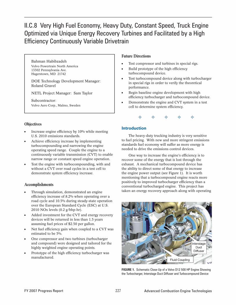
One way to increase the engine’s efficiency is to recover some of the energy that is lost through the exhaust. A mechanical turbocompound device has the ability to direct some of that energy to increase the engine power output (see Figure 1). It is worth mentioning that a turbocompound engine reacts more positively to improved turbocharger efficiency than a conventional turbocharged engine. This project has taken an energy recovery approach along with operating
FiGure 1. Schematic Close-Up of a Volvo D12 500 HP Engine Showing the Turbocharger, Interstage Duct Diffuser and Turbocompound Device
227 Advanced Combustion Engine Technologies
II.C Critical Enabling Technologies Habibzadeh – Volvo Powertrain North America
the engine in a different speed range than typical of today’s engines. Narrowing the engine operating speed allows the designer to select the optimum speed where engine efficiency is highest. Conventional standard transmissions operate with gear steps too great to run the engine at a constant or narrow range but with the development of a CVT, narrow range operation is possible which will allow the engine to operate at peak efficiency over its entire operating range.
A narrow operating range leads to lower average engine speed which allows valve timing optimization and also use of a compressor with a vaned diffuser which has higher effi ciency.
Approach
In order to achieve the efficiency, four techniques were combined: mechanical turbocompounding, high efficiency turbochargers, narrow range engine operation and optimized combustion and valve timings.
Detailed simulations were done based on a Volvo MD13 (485 HP/2600 Nm) engine to determine the benefit of reducing the engine speed and its impact on efficiency. The simulations guided the development of the narrow engine speed range approach and allowed the study of different operating ranges so the best one could be chosen. Simulations were also done to determine the best turbocharger and turbocompound device combination that would return the highest efficiency. Cost analyses were performed on the engine system including the CVT to determine the added cost and return on investment.
Based on the engine simulations, prototype turbocharger and turbocompound hardware had to be designed and manufactured. The prototype hardware will be installed onto a 13L Volvo engine for testing to compare simulation with actual results.
The final plan is to assemble the engine with the high efficiency turbocharger, turbocompound device, and CVT, and place in a test cell capable of running the same road cycles that were used during the simulation phase. The results of the testing will be compared to that determined through vehicle simulations.
Results
Previously Achieved
The simulation result showed:
• Fuel consumption reduction compared to the U.S. 2007 reference engine is 8.2 % when using the U.S. 2007 road cycle with weighting factors (fl at 70%, rolling hills 25% and hilly 5%) and 10.5 % when using the ESC cycle, achieved by:
– High effi ciency turbocharger
– High efficiency mechanical turbocompound device
– Narrow range engine operation which allows optimized camshaft timings and combustion
• A narrow speed engine (1,000-1,300 rpm) is more efficient than constant speed - especially when the engine is not working in the full power range.
• The additional cost of the turbocharger, turbocompound device, and other modifi cations to the engine can be paid back in less than 15 months (assumed fuel price of $2.50 per gallon and the lowest recovered effi ciency).
Recent Achievements
For the stress analysis (low-cycle fatigue), thermodynamic input in form of transient turbocharger speed, temperature, pressures etc. are required. In order to extract these data, a simplified truck operating cycle is defined for cold-starts, warm-starts and load/speed changes.
Both steady-state and high altitude (1,675 m/25°C) simulations have been performed for the MD13 TC engine with updated boundary conditions and turbo maps. The results are obtained by cycle optimization at “engine-out” conditions, i.e. NOx and soot emissions.
Turbocharger
The turbocharger, as seen in Figure 2, has a high performance compressor and radial turbine. The design speed is around 110,000 rpm. The turbine has a housing which is of the double entry type enabling each group of cylinders to feed 180° of the turbine’s circumference.
FIGURE 2. Computer Aided Design Drawing of the Turbocharger Unit
Advanced Combustion Engine Technologies 228 FY 2007 Progress Report
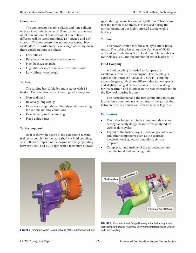
Habibzadeh – Volvo Powertrain North America II.C Critical Enabling Technologies
Compressor
The compressor has nine blades and nine splitters with an inlet hub diameter of 17 mm, inlet tip diameter of 54 mm and outlet diameter of 94 mm. Three diffusers will be tested (nominal, 1.5° opened and 1.5° closed). The compressor has no inducer shroud bleed as standard. In order to achieve a large operating range these considerations are taken:
• LSA diffuser
• Relatively low impeller blade number
• High backsweep angle
• High diffuser inlet to impeller exit radius ratio
• Low diffuser vane height
Turbine
The turbine has 11 blades and a stator with 18 blades. Considerations to achieve high efficiency are:
• Non-scalloped
• Relatively long axially
• Extensive computational fluid dynamics modeling for various running conditions
• Double entry turbine housing
• Fixed guide vanes
Turbocompound
As it is shown in Figure 3, the compound turbine is directly coupled to the crankshaft via fluid coupling, so it follows the speed of the engine normally operating between 1,000 and 1,300 rpm with a maximum allowed
speed during engine braking of 1,900 rpm. This means that the turbine is relatively low stressed during the normal operation but highly stressed during engine braking.
Turbine
The power turbine is of the axial type and it has a stator. The turbine has an outside diameter of Ø118 mm and an inside diameter of Ø80 mm. The number of rotor blades is 23 and the number of stator blades is 17.
Fluid Coupling
A fluid coupling is needed to dampen the oscillations from the piston engine. The coupling is equal to the European Volvo D12 500 HP coupling except the gears, which are different due to new speeds and slightly changed center distance. The new design for the geartrain and interface to the rear transmission in the flywheel housing is done.
The turbocharger and the turbocompound units are located on a common axis which means the gas conduit between them is annular as it can be seen in Figure 4.
summary
• The turbocharger and turbocompound device are aerodynamically designed and stress analyzed for various duty cycles.
• Layout of the turbocharger, turbocompound device, and other components such as the geartrain, flywheel housing, exhaust manifold, etc. are prepared.
• Compressor and turbine of the turbocharger are manufactured and are being tested.
FiGure 3. Computer Aided Design Drawing of the Turbocompound Unit
FiGure 4. Computer Aided Design Drawing of the Turbocharger and Turbocompound Device Assembly Showing the Interstage Duct Diffuser and Fluid Coupling
FY 2007 Progress Report 22� Advanced Combustion Engine Technologies
II.C Critical Enabling Technologies Habibzadeh – Volvo Powertrain North America
• Base engine testing (ESC, Federal Test Procedure, road cycle) are done on a standard MD13 engine.
• Future plans
– To test the compressor with a standard production turbocharger with three different diffusers.
– To assemble and set instrumentation on the turbocharger and test in a hot-gas stand.
– To manufacture and test the turbocompound unit.
– To perform a functional test of the turbocharger and turbocompound device on an MD13 engine.
FY 2007 publications/presentations
1. Quarterly Reports DOE/NETL, Contract – DE-FC-05NT45421, 2006-2007.
2. FY2006 Report, DOE/NETL, Contract – DE-FC-05NT45421, 2006.
Advanced Combustion Engine Technologies 2�0 FY 2007 Progress Report
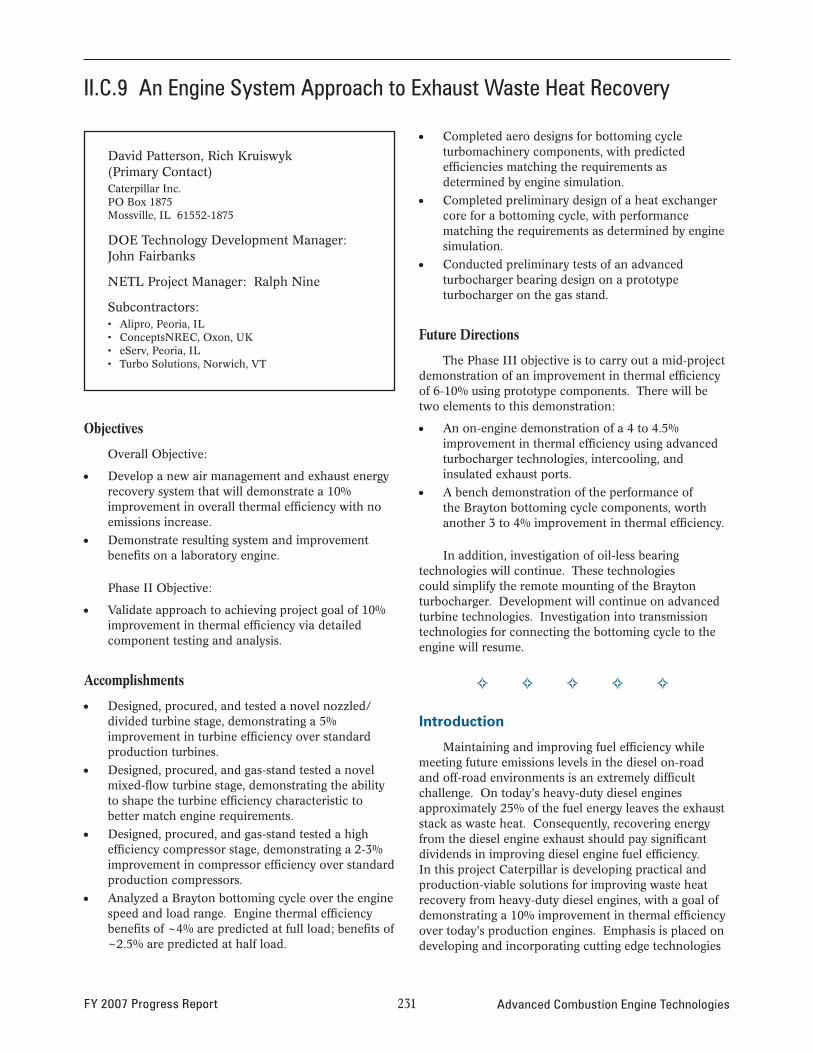
II.C.9 An Engine System Approach to Exhaust Waste Heat Recovery
David Patterson, Rich Kruiswyk (Primary Contact)Caterpillar Inc.PO Box 1875 Mossville, IL 61552-1875
DOE Technology Development Manager: John Fairbanks
NETL Project Manager: Ralph Nine
Subcontractors: • Alipro, Peoria, IL • ConceptsNREC, Oxon, UK • eServ, Peoria, IL • Turbo Solutions, Norwich, VT
Objectives
Overall Objective:
• Develop a new air management and exhaust energy recovery system that will demonstrate a 10% improvement in overall thermal efficiency with no emissions increase.
• Demonstrate resulting system and improvement benefits on a laboratory engine.
Phase II Objective:
• Validate approach to achieving project goal of 10% improvement in thermal efficiency via detailed component testing and analysis.
Accomplishments
• Designed, procured, and tested a novel nozzled/ divided turbine stage, demonstrating a 5% improvement in turbine efficiency over standard production turbines.
• Designed, procured, and gas-stand tested a novel mixed-flow turbine stage, demonstrating the ability to shape the turbine efficiency characteristic to better match engine requirements.
• Designed, procured, and gas-stand tested a high efficiency compressor stage, demonstrating a 2-3% improvement in compressor efficiency over standard production compressors.
• Analyzed a Brayton bottoming cycle over the engine speed and load range. Engine thermal efficiency benefits of ~4% are predicted at full load; benefits of ~2.5% are predicted at half load.
• Completed aero designs for bottoming cycle turbomachinery components, with predicted efficiencies matching the requirements as determined by engine simulation.
• Completed preliminary design of a heat exchanger core for a bottoming cycle, with performance matching the requirements as determined by engine simulation.
• Conducted preliminary tests of an advanced turbocharger bearing design on a prototype turbocharger on the gas stand.
Future Directions
The Phase III objective is to carry out a mid-project demonstration of an improvement in thermal efficiency of 6-10% using prototype components. There will be two elements to this demonstration:
• An on-engine demonstration of a 4 to 4.5% improvement in thermal efficiency using advanced turbocharger technologies, intercooling, and insulated exhaust ports.
• A bench demonstration of the performance of the Brayton bottoming cycle components, worth another 3 to 4% improvement in thermal efficiency.
In addition, investigation of oil-less bearing technologies will continue. These technologies could simplify the remote mounting of the Brayton turbocharger. Development will continue on advanced turbine technologies. Investigation into transmission technologies for connecting the bottoming cycle to the engine will resume.
G G G G G
introduction
Maintaining and improving fuel efficiency while meeting future emissions levels in the diesel on-road and off-road environments is an extremely difficult challenge. On today’s heavy-duty diesel engines approximately 25% of the fuel energy leaves the exhaust stack as waste heat. Consequently, recovering energy from the diesel engine exhaust should pay significant dividends in improving diesel engine fuel efficiency. In this project Caterpillar is developing practical and production-viable solutions for improving waste heat recovery from heavy-duty diesel engines, with a goal of demonstrating a 10% improvement in thermal efficiency over today’s production engines. Emphasis is placed on developing and incorporating cutting edge technologies
FY 2007 Progress Report 2�� Advanced Combustion Engine Technologies
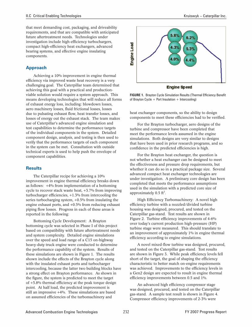
II.C Critical Enabling Technologies Kruiswyk – Caterpillar Inc.
that meet demanding cost, packaging, and driveability requirements, and that are compatible with anticipated future aftertreatment needs. Technologies under investigation include high-efficiency turbochargers, compact high-efficiency heat exchangers, advanced bearing systems, and effective engine insulating components.
Approach
Achieving a 10% improvement in engine thermal efficiency via improved waste heat recovery is a very challenging goal. The Caterpillar team determined that achieving this goal with a practical and production-viable solution would require a system approach. This means developing technologies that will reduce all forms of exhaust energy loss, including: blowdown losses, aero machinery losses, fluid frictional losses, losses due to pulsating exhaust flow, heat transfer losses, and losses of energy out the exhaust stack. The team makes use of Caterpillar’s advanced engine simulation and test capabilities to determine the performance targets of the individual components in the system. Detailed component design, analysis, and testing is then used to verify that the performance targets of each component in the system can be met. Consultation with outside technical experts is used to help push the envelope of component capabilities.
results
The Caterpillar recipe for achieving a 10% improvement in engine thermal efficiency breaks down as follows: +4% from implementation of a bottoming cycle to recover stack waste heat, +3.7% from improving turbocharger efficiencies, +1.3% from intercooling the series turbocharging system, +0.5% from insulating the engine exhaust ports, and +0.5% from reducing exhaust piping flow losses. Progress in each of these areas is reported in the following:
Bottoming Cycle Development: A Brayton bottoming cycle was selected in Phase I of this project based on compatibility with future aftertreatment needs and system complexity. Detailed engine simulations over the speed and load range of a C15 on-highway heavy-duty truck engine were conducted to determine the performance capability of the system. Results of these simulations are shown in Figure 1. The results shown include the effects of the Brayton cycle along with the insulated exhaust ports and turbocharger intercooling, because the latter two building blocks have a strong effect on Brayton performance. As shown in the figure, the system is predicted to meet the target of +5.8% thermal efficiency at the peak torque design point. At half load, the predicted improvement is still an impressive +4%. These simulations are based on assumed efficiencies of the turbomachinery and
FiGure 1. Brayton Cycle Simulation Results (Thermal Efficiency Benefit of Brayton Cycle + Port Insulation + Intercooling)
heat exchanger components, so the ability to design components to meet these efficiencies had to be verified.
For the Brayton turbocharger, aero designs of the turbine and compressor have been completed that meet the performance levels assumed in the engine simulations. Both designs are very similar to designs that have been used in prior research programs, and so confidence in the predicted efficiencies is high.
For the Brayton heat exchanger, the question is not whether a heat exchanger can be designed to meet the effectiveness and pressure drop requirements, but whether it can do so in a practical package size. Several advanced compact heat exchanger technologies are under investigation. A preliminary core design has been completed that meets the performance assumptions used in the simulation with a predicted core size of approximately 0.5 ft3.
High Efficiency Turbomachinery: A novel high efficiency turbine with a nozzled/divided turbine housing was designed, procured, and tested on the Caterpillar gas-stand. Test results are shown in Figure 2. Turbine efficiency improvements of 4-6% over today’s current production high-pressure (HP) turbine stage were measured. This should translate to an improvement of approximately 1% in engine thermal efficiency according to engine simulations.
A novel mixed-flow turbine was designed, procured, and tested on the Caterpillar gas-stand. Test results are shown in Figure 3. While peak efficiency levels fell short of the target, the goal of shaping the efficiency characteristic to better match on-engine requirements was achieved. Improvements to the efficiency levels in a Gen2 design are expected to result in engine thermal efficiency improvements between 0.5 and 1%.
An advanced high efficiency compressor stage was designed, procured, and tested on the Caterpillar gas-stand. A sample test result is shown in Figure 4. Compressor efficiency improvements of 2-3% were
Advanced Combustion Engine Technologies 2�2 FY 2007 Progress Report
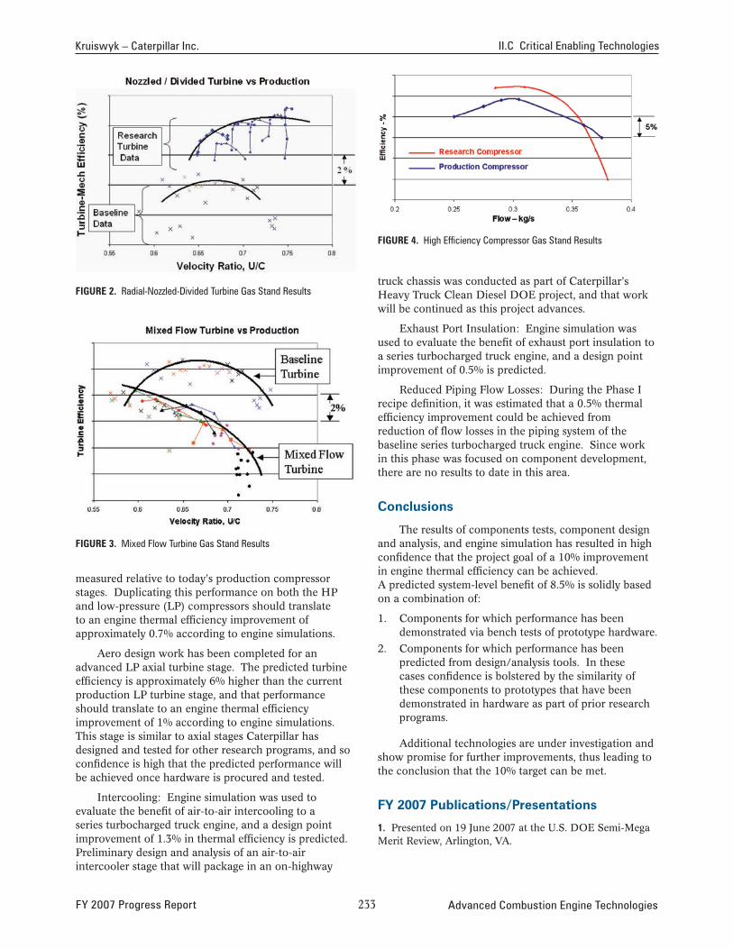
Kruiswyk – Caterpillar Inc. II.C Critical Enabling Technologies
FiGure 2. Radial-Nozzled-Divided Turbine Gas Stand Results
FiGure 3. Mixed Flow Turbine Gas Stand Results
measured relative to today’s production compressor stages. Duplicating this performance on both the HP and low-pressure (LP) compressors should translate to an engine thermal efficiency improvement of approximately 0.7% according to engine simulations.
Aero design work has been completed for an advanced LP axial turbine stage. The predicted turbine efficiency is approximately 6% higher than the current production LP turbine stage, and that performance should translate to an engine thermal efficiency improvement of 1% according to engine simulations. This stage is similar to axial stages Caterpillar has designed and tested for other research programs, and so confidence is high that the predicted performance will be achieved once hardware is procured and tested.
Intercooling: Engine simulation was used to evaluate the benefit of air-to-air intercooling to a series turbocharged truck engine, and a design point improvement of 1.3% in thermal efficiency is predicted. Preliminary design and analysis of an air-to-air intercooler stage that will package in an on-highway
FiGure 4. High Efficiency Compressor Gas Stand Results
truck chassis was conducted as part of Caterpillar’s Heavy Truck Clean Diesel DOE project, and that work will be continued as this project advances.
Exhaust Port Insulation: Engine simulation was used to evaluate the benefit of exhaust port insulation to a series turbocharged truck engine, and a design point improvement of 0.5% is predicted.
Reduced Piping Flow Losses: During the Phase I recipe definition, it was estimated that a 0.5% thermal efficiency improvement could be achieved from reduction of flow losses in the piping system of the baseline series turbocharged truck engine. Since work in this phase was focused on component development, there are no results to date in this area.
conclusions
The results of components tests, component design and analysis, and engine simulation has resulted in high confidence that the project goal of a 10% improvement in engine thermal efficiency can be achieved. A predicted system-level benefit of 8.5% is solidly based on a combination of:
1. Components for which performance has been demonstrated via bench tests of prototype hardware.
2. Components for which performance has been predicted from design/analysis tools. In these cases confidence is bolstered by the similarity of these components to prototypes that have been demonstrated in hardware as part of prior research programs.
Additional technologies are under investigation and show promise for further improvements, thus leading to the conclusion that the 10% target can be met.
FY 2007 publications/presentations
1. Presented on 19 June 2007 at the U.S. DOE Semi-Mega Merit Review, Arlington, VA.
FY 2007 Progress Report 2�� Advanced Combustion Engine Technologies

II.C Critical Enabling Technologies Kruiswyk – Caterpillar Inc.
2. Presented on 15 August 2007 at the U.S. DOE Diesel Engine-Efficiency and Emissions Research (DEER) conference, Detroit, MI.
Advanced Combustion Engine Technologies 2�� FY 2007 Progress Report
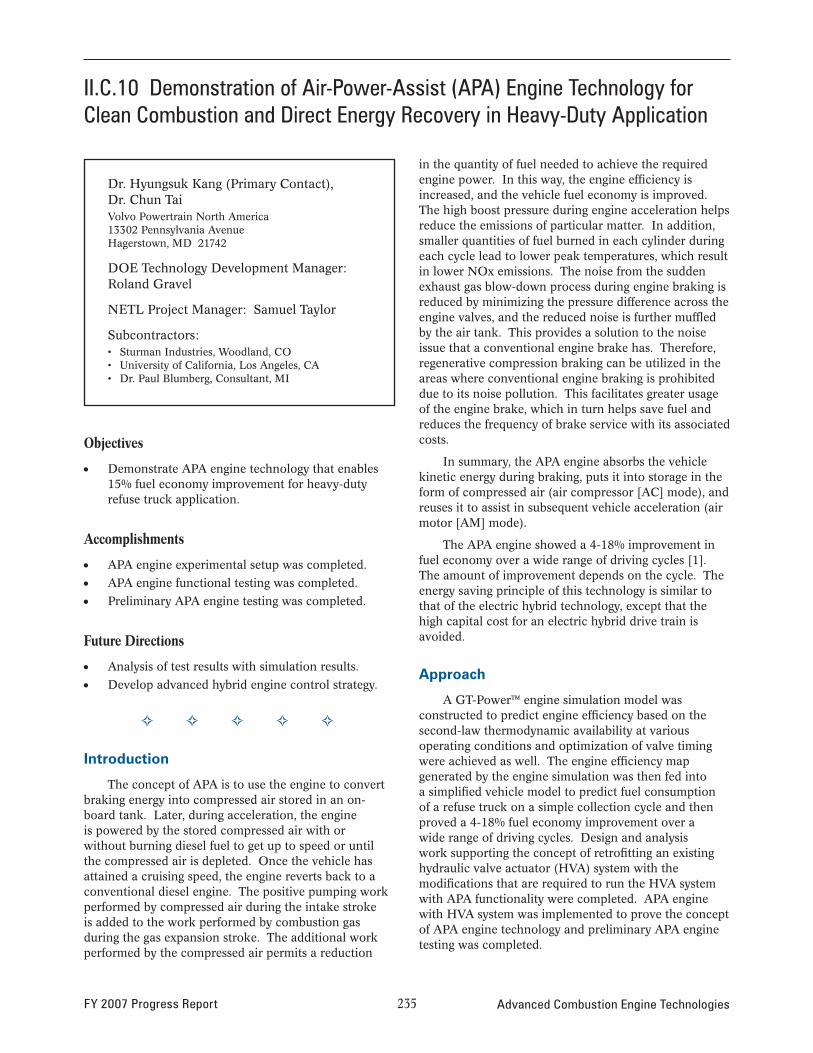
II.C.10 Demonstration of Air-Power-Assist (APA) Engine Technology for Clean Combustion and Direct Energy Recovery in Heavy-Duty Application
Dr. Hyungsuk Kang (Primary Contact), Dr. Chun Tai Volvo Powertrain North America 13302 Pennsylvania Avenue Hagerstown, MD 21742
DOE Technology Development Manager: Roland Gravel
NETL Project Manager: Samuel Taylor
Subcontractors: • Sturman Industries, Woodland, CO • University of California, Los Angeles, CA • Dr. Paul Blumberg, Consultant, MI
Objectives
• Demonstrate APA engine technology that enables 15% fuel economy improvement for heavy-duty refuse truck application.
Accomplishments
• APA engine experimental setup was completed.
• APA engine functional testing was completed.
• Preliminary APA engine testing was completed.
Future Directions
• Analysis of test results with simulation results.
• Develop advanced hybrid engine control strategy.
� � � � �
Introduction
The concept of APA is to use the engine to convert braking energy into compressed air stored in an onboard tank. Later, during acceleration, the engine is powered by the stored compressed air with or without burning diesel fuel to get up to speed or until the compressed air is depleted. Once the vehicle has attained a cruising speed, the engine reverts back to a conventional diesel engine. The positive pumping work performed by compressed air during the intake stroke is added to the work performed by combustion gas during the gas expansion stroke. The additional work performed by the compressed air permits a reduction
in the quantity of fuel needed to achieve the required engine power. In this way, the engine effi ciency is increased, and the vehicle fuel economy is improved. The high boost pressure during engine acceleration helps reduce the emissions of particular matter. In addition, smaller quantities of fuel burned in each cylinder during each cycle lead to lower peak temperatures, which result in lower NOx emissions. The noise from the sudden exhaust gas blow-down process during engine braking is reduced by minimizing the pressure difference across the engine valves, and the reduced noise is further muffl ed by the air tank. This provides a solution to the noise issue that a conventional engine brake has. Therefore, regenerative compression braking can be utilized in the areas where conventional engine braking is prohibited due to its noise pollution. This facilitates greater usage of the engine brake, which in turn helps save fuel and reduces the frequency of brake service with its associated costs.
In summary, the APA engine absorbs the vehicle kinetic energy during braking, puts it into storage in the form of compressed air (air compressor [AC] mode), and reuses it to assist in subsequent vehicle acceleration (air motor [AM] mode).
The APA engine showed a 4-18% improvement in fuel economy over a wide range of driving cycles [1]. The amount of improvement depends on the cycle. The energy saving principle of this technology is similar to that of the electric hybrid technology, except that the high capital cost for an electric hybrid drive train is avoided.
Approach
A GT-Power™ engine simulation model was constructed to predict engine efficiency based on the second-law thermodynamic availability at various operating conditions and optimization of valve timing were achieved as well. The engine effi ciency map generated by the engine simulation was then fed into a simplified vehicle model to predict fuel consumption of a refuse truck on a simple collection cycle and then proved a 4-18% fuel economy improvement over a wide range of driving cycles. Design and analysis work supporting the concept of retrofitting an existing hydraulic valve actuator (HVA) system with the modifications that are required to run the HVA system with APA functionality were completed. APA engine with HVA system was implemented to prove the concept of APA engine technology and preliminary APA engine testing was completed.
FY 2007 Progress Report 235 Advanced Combustion Engine Technologies
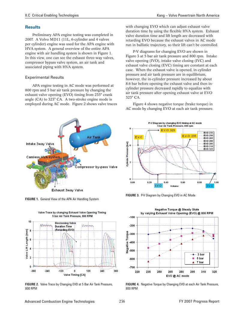
II.C Critical Enabling Technologies Kang – Volvo Powertrain North America
Results
Preliminary APA engine testing was completed in 2007. A Volvo MD11 (11L, 6-cylinder and 4 valves per cylinder) engine was used for the APA engine with HVA system. A general overview of the entire APA engine with air handling system is shown in Figure 1. In this view, one can see the exhaust three-way valves, compressor bypass valve system, an air tank and associated piping with HVA system.
Experimental Results
APA engine testing in AC mode was performed at 800 rpm and 5 bar air tank pressure by changing the exhaust valve opening (EVO) timing from 235° crank angle (CA) to 323° CA. A two-stroke engine mode is employed during AC mode. Figure 2 shows valve traces
with changing EVO which can adjust exhaust valve duration time by using the flexible HVA system. Exhaust valve duration time and lift length are decreased with retarding EVO because the exhaust valves in AC mode run in ballistic trajectory, so their lift can’t be controlled.
P-V diagrams for changing EVO are shown in Figure 3 at 5 bar air tank pressure and 800 rpm. Intake valve opening (IVO), intake valve closing (IVC) and exhaust valve closing (EVC) timing are constant at each case. When the exhaust valve is opened, in-cylinder pressure and air tank pressure are in equilibrium, however, the in-cylinder pressure increased by about 8.6 bar before opening the exhaust valve and then in-cylinder pressure decreased rapidly to equalize with air tank pressure after opening exhaust valve at EVO 323° CA.
Figure 4 shows negative torque (brake torque) in AC mode by changing EVO at each air tank pressure.
FIGURE 1. General View of the APA Air Handling System FIGURE 3. P-V Diagram by Changing EVO in AC Mode
FIGURE 2. Valve Trace by Changing EVO at 5 Bar Air Tank Pressure, 800 RPM
FIGURE 4. Negative Torque by Changing EVO at each Air Tank Pressure, 800 RPM
Advanced Combustion Engine Technologies 236 FY 2007 Progress Report
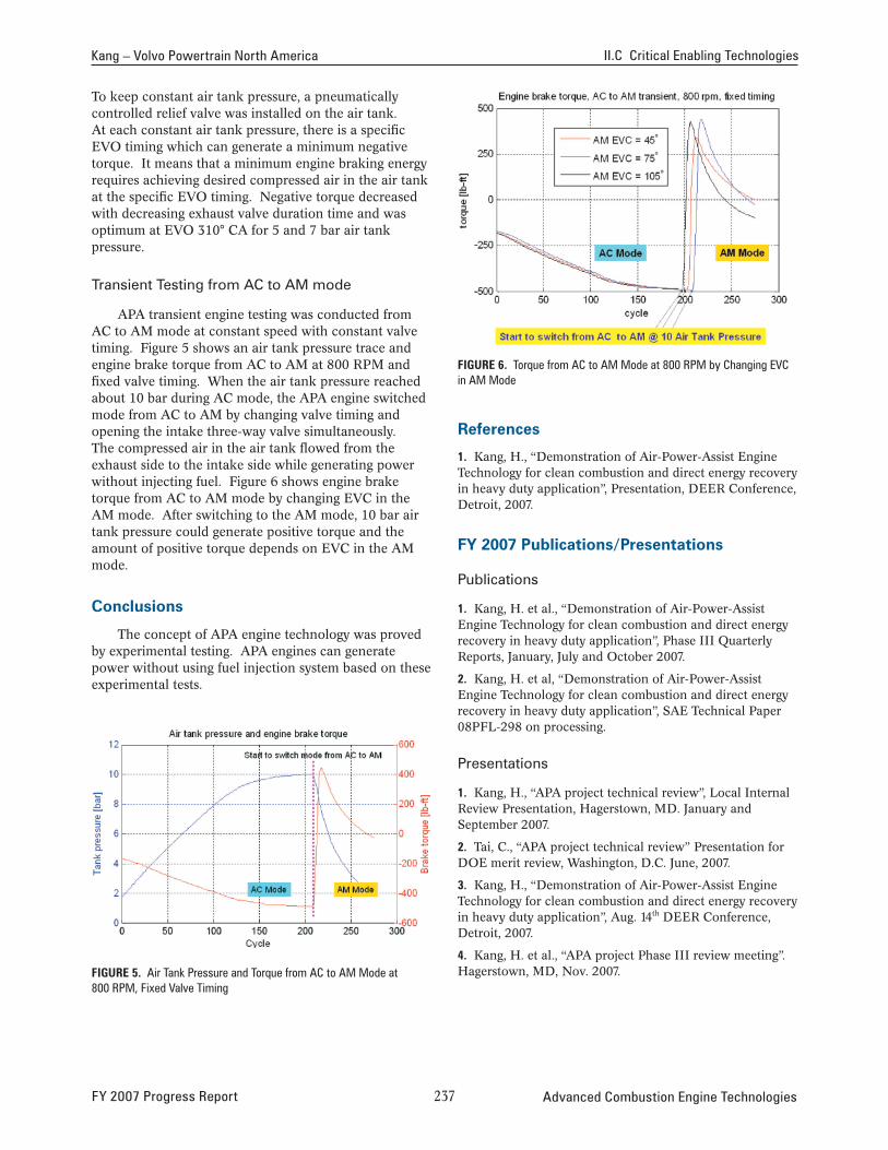
Kang – Volvo Powertrain North America II.C Critical Enabling Technologies
To keep constant air tank pressure, a pneumatically controlled relief valve was installed on the air tank. At each constant air tank pressure, there is a specifi c EVO timing which can generate a minimum negative torque. It means that a minimum engine braking energy requires achieving desired compressed air in the air tank at the specific EVO timing. Negative torque decreased with decreasing exhaust valve duration time and was optimum at EVO 310° CA for 5 and 7 bar air tank pressure.
Transient Testing from AC to AM mode
APA transient engine testing was conducted from AC to AM mode at constant speed with constant valve timing. Figure 5 shows an air tank pressure trace and engine brake torque from AC to AM at 800 RPM and fixed valve timing. When the air tank pressure reached about 10 bar during AC mode, the APA engine switched mode from AC to AM by changing valve timing and opening the intake three-way valve simultaneously. The compressed air in the air tank flowed from the exhaust side to the intake side while generating power without injecting fuel. Figure 6 shows engine brake torque from AC to AM mode by changing EVC in the AM mode. After switching to the AM mode, 10 bar air tank pressure could generate positive torque and the amount of positive torque depends on EVC in the AM mode.
Conclusions
The concept of APA engine technology was proved by experimental testing. APA engines can generate power without using fuel injection system based on these experimental tests.
FIGURE 5. Air Tank Pressure and Torque from AC to AM Mode at 800 RPM, Fixed Valve Timing
FIGURE 6. Torque from AC to AM Mode at 800 RPM by Changing EVC in AM Mode
References
1. Kang, H., “Demonstration of Air-Power-Assist Engine Technology for clean combustion and direct energy recovery in heavy duty application”, Presentation, DEER Conference, Detroit, 2007.
FY 2007 Publications/Presentations
Publications
1. Kang, H. et al., “Demonstration of Air-Power-Assist Engine Technology for clean combustion and direct energy recovery in heavy duty application”, Phase III Quarterly Reports, January, July and October 2007.
2. Kang, H. et al, “Demonstration of Air-Power-Assist Engine Technology for clean combustion and direct energy recovery in heavy duty application”, SAE Technical Paper 08PFL-298 on processing.
Presentations
1. Kang, H., “APA project technical review”, Local Internal Review Presentation, Hagerstown, MD. January and September 2007.
2. Tai, C., “APA project technical review” Presentation for DOE merit review, Washington, D.C. June, 2007.
3. Kang, H., “Demonstration of Air-Power-Assist Engine Technology for clean combustion and direct energy recovery in heavy duty application”, Aug. 14th DEER Conference, Detroit, 2007.
4. Kang, H. et al., “APA project Phase III review meeting”. Hagerstown, MD, Nov. 2007.
FY 2007 Progress Report 237 Advanced Combustion Engine Technologies

Advanced Combustion Engine Technologies 2�� FY 2007 Progress Report