Embed Size (px)
Citation preview
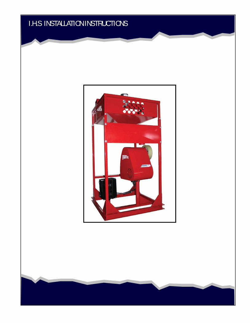
I.H.S INSTALLATION INSTRUCTIONS
2
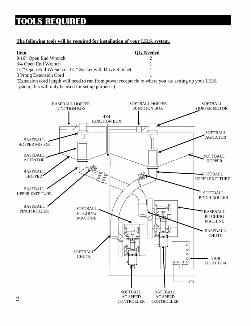
TOOLS REQUIRED
The following tools will be required for installation of your I.H.S. system. Item Qty Needed 9/16” Open End Wrench 2 3/4 Open End Wrench 1 1/2” Open End Wrench or 1/2” Socket with Drive Ratchet 1 3 Prong Extension Cord 1 (Extension cord length will need to run from power receptacle to where you are setting up your I.H.S. system, this will only be used for set up purposes)
BASEBALL HOPPER
SOFTBALL HOPPER
BASEBALL PITCHING MACHINE
SOFTBALL PITCHING MACHINE
SA-8 LIGHT BOX
BASEBALL PINCH ROLLER
SOFTBALL PINCH ROLLER
BASEBALL AC SPEED
CONTROLLER
SOFTBALL AC SPEED
CONTROLLER
BASEBALL UPPER EXIT TUBE
SOFTBALL UPPER EXIT TUBE
BASEBALL CHUTE
SOFTBALL CHUTE
BASEBALL HOPPER MOTOR
SOFTBALL HOPPER MOTOR
4X4 JUNCTION BOX
SOFTBALL HOPPER JUNCTION BOX
BASEBALL HOPPER JUNCTION BOX
BASEBALL AGITATOR
SOFTBALL AGITATOR
3
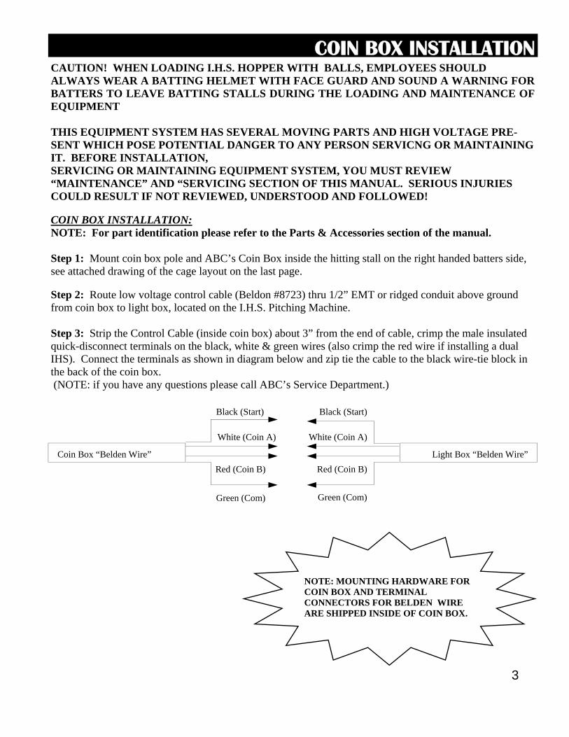
CAUTION! WHEN LOADING I.H.S. HOPPER WITH BALLS, EMPLOYEES SHOULD ALWAYS WEAR A BATTING HELMET WITH FACE GUARD AND SOUND A WARNING FOR BATTERS TO LEAVE BATTING STALLS DURING THE LOADING AND MAINTENANCE OF EQUIPMENT THIS EQUIPMENT SYSTEM HAS SEVERAL MOVING PARTS AND HIGH VOLTAGE PRE-SENT WHICH POSE POTENTIAL DANGER TO ANY PERSON SERVICNG OR MAINTAINING IT. BEFORE INSTALLATION, SERVICING OR MAINTAINING EQUIPMENT SYSTEM, YOU MUST REVIEW “MAINTENANCE” AND “SERVICING SECTION OF THIS MANUAL. SERIOUS INJURIES COULD RESULT IF NOT REVIEWED, UNDERSTOOD AND FOLLOWED! COIN BOX INSTALLATION: NOTE: For part identification please refer to the Parts & Accessories section of the manual. Step 1: Mount coin box pole and ABC’s Coin Box inside the hitting stall on the right handed batters side, see attached drawing of the cage layout on the last page. Step 2: Route low voltage control cable (Beldon #8723) thru 1/2” EMT or ridged conduit above ground from coin box to light box, located on the I.H.S. Pitching Machine. Step 3: Strip the Control Cable (inside coin box) about 3” from the end of cable, crimp the male insulated quick-disconnect terminals on the black, white & green wires (also crimp the red wire if installing a dual IHS). Connect the terminals as shown in diagram below and zip tie the cable to the black wire-tie block in the back of the coin box. (NOTE: if you have any questions please call ABC’s Service Department.)
Coin Box “Belden Wire” Light Box “Belden Wire”
Black (Start)
White (Coin A)
Black (Start)
White (Coin A)
Green (Com) Green (Com)
NOTE: MOUNTING HARDWARE FOR COIN BOX AND TERMINAL CONNECTORS FOR BELDEN WIRE ARE SHIPPED INSIDE OF COIN BOX.
Red (Coin B) Red (Coin B)
COIN BOX INSTALLATION
4
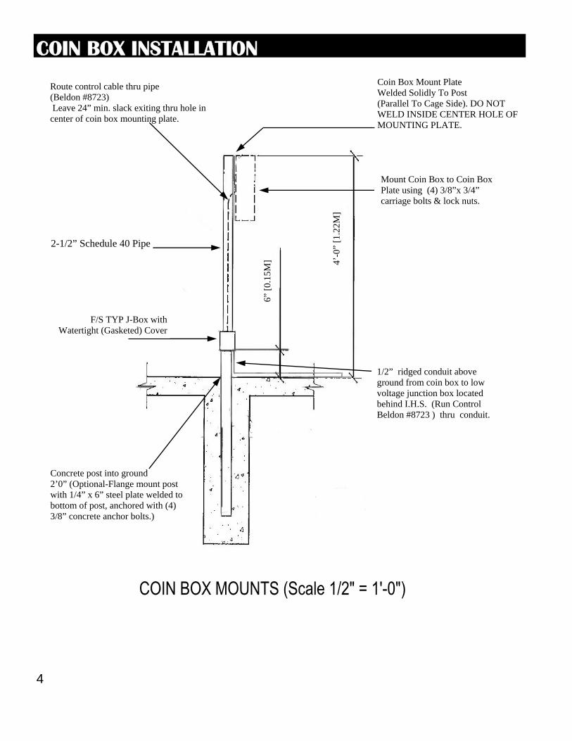
1/2” ridged conduit above ground from coin box to low voltage junction box located behind I.H.S. (Run Control Beldon #8723 ) thru conduit.
Concrete post into ground 2’0” (Optional-Flange mount post with 1/4” x 6” steel plate welded to bottom of post, anchored with (4) 3/8” concrete anchor bolts.)
Route control cable thru pipe (Beldon #8723) Leave 24” min. slack exiting thru hole in center of coin box mounting plate.
2-1/2” Schedule 40 Pipe
F/S TYP J-Box with Watertight (Gasketed) Cover
4’-0
” [1
.22M
]
6” [
0.15
M]
Coin Box Mount Plate Welded Solidly To Post (Parallel To Cage Side). DO NOT WELD INSIDE CENTER HOLE OF MOUNTING PLATE.
Mount Coin Box to Coin Box Plate using (4) 3/8”x 3/4” carriage bolts & lock nuts.
COIN BOX INSTALLATION
5
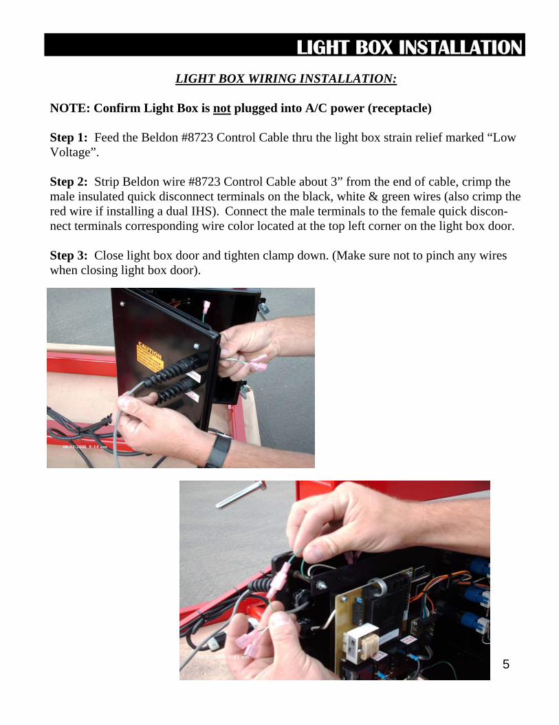
LIGHT BOX WIRING INSTALLATION:
NOTE: Confirm Light Box is not plugged into A/C power (receptacle) Step 1: Feed the Beldon #8723 Control Cable thru the light box strain relief marked “Low Voltage”. Step 2: Strip Beldon wire #8723 Control Cable about 3” from the end of cable, crimp the male insulated quick disconnect terminals on the black, white & green wires (also crimp the red wire if installing a dual IHS). Connect the male terminals to the female quick discon-nect terminals corresponding wire color located at the top left corner on the light box door. Step 3: Close light box door and tighten clamp down. (Make sure not to pinch any wires when closing light box door).
LIGHT BOX INSTALLATION
6
DUAL HOPPER INSTALLATION
THE FOLLOWING STEPS ARE ONLY REQUIRED IF INSTALLING A DUAL MACHINE IHS. IF INSTALLING A SINGLE MACHINE IHS PLEASE PROCEED TO THE PITCHING
MACHINE SETUP INSTRUCTIONS.
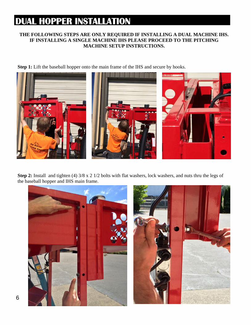
Step 1: Lift the baseball hopper onto the main frame of the IHS and secure by hooks.
Step 2: Install and tighten (4) 3/8 x 2 1/2 bolts with flat washers, lock washers, and nuts thru the legs of the baseball hopper and IHS main frame.
7
DUAL HOPPER INSTALLATION
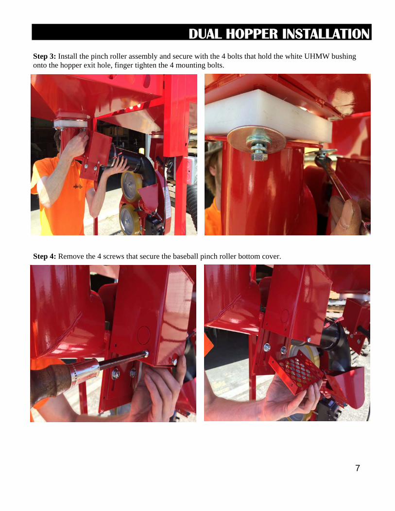
Step 3: Install the pinch roller assembly and secure with the 4 bolts that hold the white UHMW bushing onto the hopper exit hole, finger tighten the 4 mounting bolts.
Step 4: Remove the 4 screws that secure the baseball pinch roller bottom cover.
8
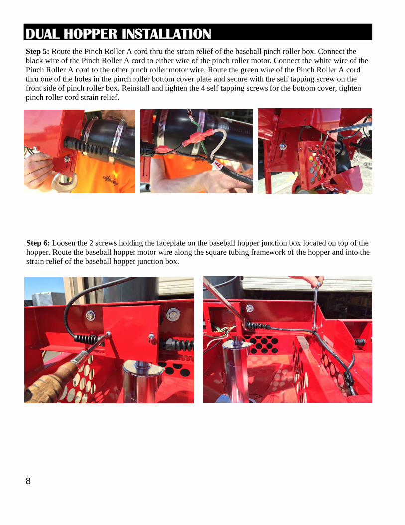
DUAL HOPPER INSTALLATION Step 5: Route the Pinch Roller A cord thru the strain relief of the baseball pinch roller box. Connect the black wire of the Pinch Roller A cord to either wire of the pinch roller motor. Connect the white wire of the Pinch Roller A cord to the other pinch roller motor wire. Route the green wire of the Pinch Roller A cord thru one of the holes in the pinch roller bottom cover plate and secure with the self tapping screw on the front side of pinch roller box. Reinstall and tighten the 4 self tapping screws for the bottom cover, tighten pinch roller cord strain relief.
Step 6: Loosen the 2 screws holding the faceplate on the baseball hopper junction box located on top of the hopper. Route the baseball hopper motor wire along the square tubing framework of the hopper and into the strain relief of the baseball hopper junction box.
9
DUAL HOPPER INSTALLATION
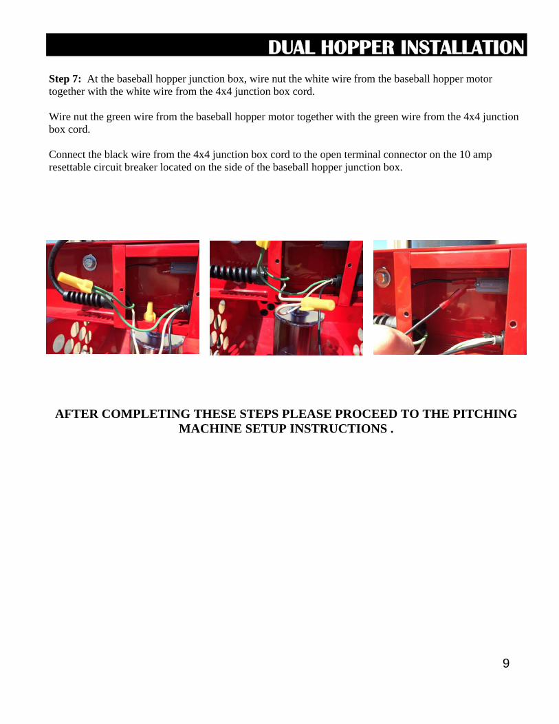
Step 7: At the baseball hopper junction box, wire nut the white wire from the baseball hopper motor together with the white wire from the 4x4 junction box cord. Wire nut the green wire from the baseball hopper motor together with the green wire from the 4x4 junction box cord. Connect the black wire from the 4x4 junction box cord to the open terminal connector on the 10 amp resettable circuit breaker located on the side of the baseball hopper junction box.
AFTER COMPLETING THESE STEPS PLEASE PROCEED TO THE PITCHING MACHINE SETUP INSTRUCTIONS .
10
PITCHING MACHINE SETUP
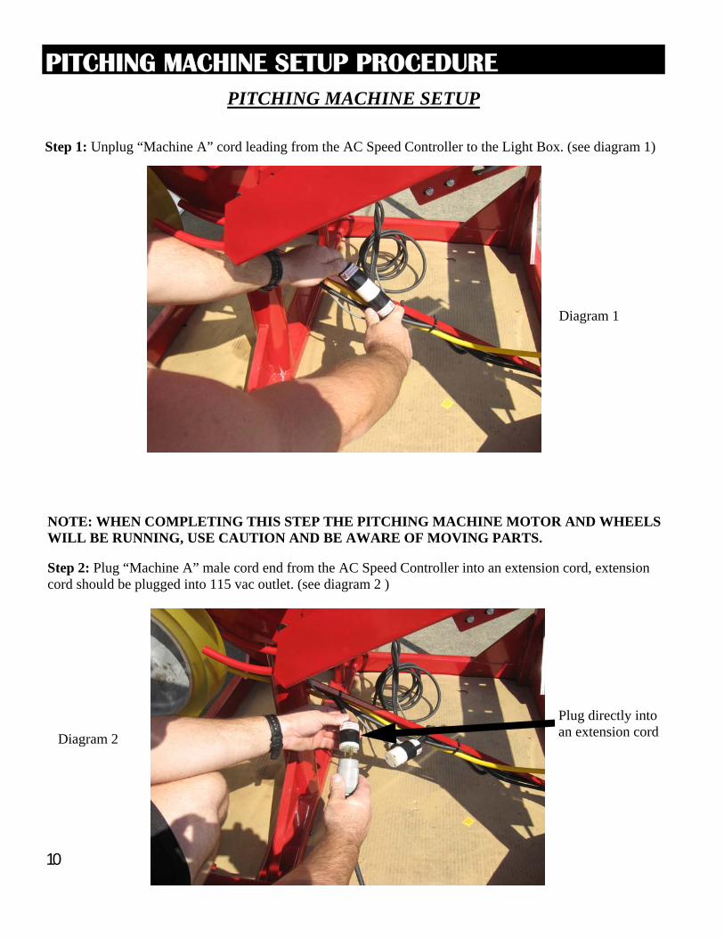
NOTE: WHEN COMPLETING THIS STEP THE PITCHING MACHINE MOTOR AND WHEELS WILL BE RUNNING, USE CAUTION AND BE AWARE OF MOVING PARTS. Step 2: Plug “Machine A” male cord end from the AC Speed Controller into an extension cord, extension cord should be plugged into 115 vac outlet. (see diagram 2 )
Plug directly into an extension cord
PITCHING MACHINE SETUP PROCEDURE
Diagram 1
Diagram 2
Step 1: Unplug “Machine A” cord leading from the AC Speed Controller to the Light Box. (see diagram 1)
11
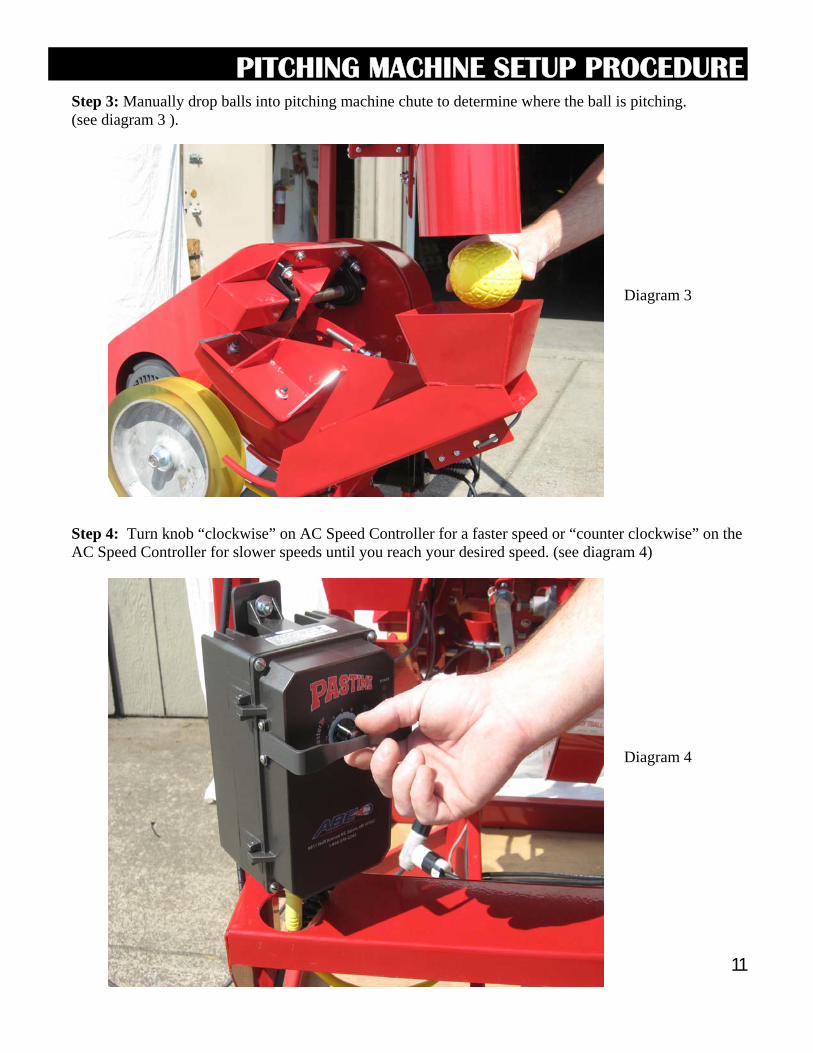
Step 3: Manually drop balls into pitching machine chute to determine where the ball is pitching. (see diagram 3 ).
PITCHING MACHINE SETUP PROCEDURE
Step 4: Turn knob “clockwise” on AC Speed Controller for a faster speed or “counter clockwise” on the AC Speed Controller for slower speeds until you reach your desired speed. (see diagram 4)
Diagram 3
Diagram 4
12
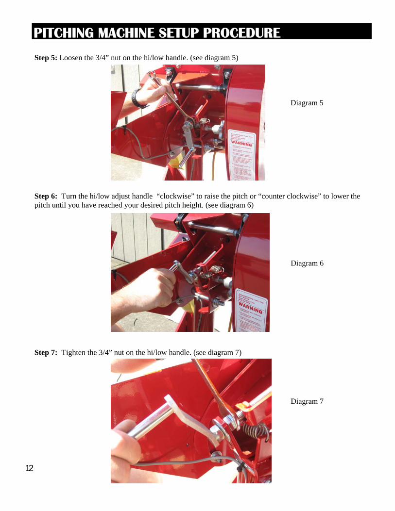
Step 5: Loosen the 3/4” nut on the hi/low handle. (see diagram 5)
Step 6: Turn the hi/low adjust handle “clockwise” to raise the pitch or “counter clockwise” to lower the pitch until you have reached your desired pitch height. (see diagram 6)
Step 7: Tighten the 3/4” nut on the hi/low handle. (see diagram 7)
PITCHING MACHINE SETUP PROCEDURE
Diagram 5
Diagram 6
Diagram 7
13
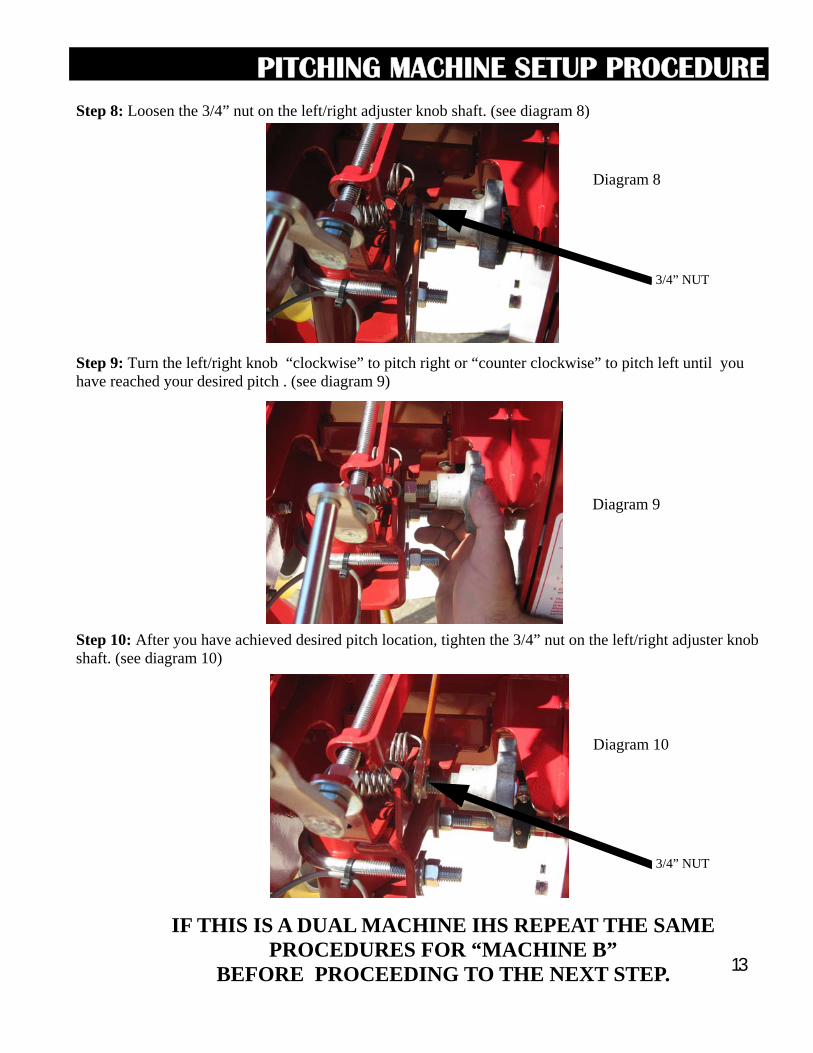
Step 8: Loosen the 3/4” nut on the left/right adjuster knob shaft. (see diagram 8)
Step 9: Turn the left/right knob “clockwise” to pitch right or “counter clockwise” to pitch left until you have reached your desired pitch . (see diagram 9)
Step 10: After you have achieved desired pitch location, tighten the 3/4” nut on the left/right adjuster knob shaft. (see diagram 10)
3/4” NUT
3/4” NUT
PITCHING MACHINE SETUP PROCEDURE
Diagram 8
Diagram 9
Diagram 10
IF THIS IS A DUAL MACHINE IHS REPEAT THE SAME PROCEDURES FOR “MACHINE B”
BEFORE PROCEEDING TO THE NEXT STEP.
14
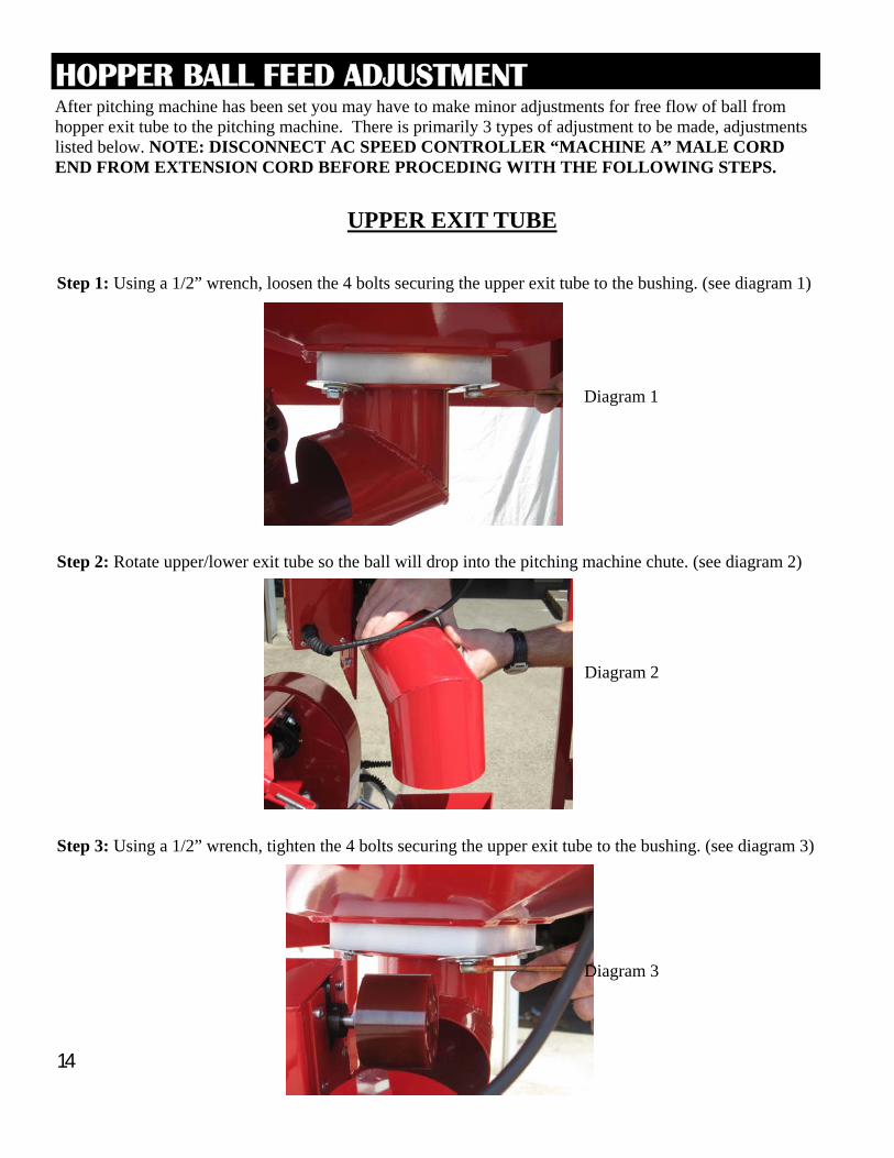
After pitching machine has been set you may have to make minor adjustments for free flow of ball from hopper exit tube to the pitching machine. There is primarily 3 types of adjustment to be made, adjustments listed below. NOTE: DISCONNECT AC SPEED CONTROLLER “MACHINE A” MALE CORD END FROM EXTENSION CORD BEFORE PROCEDING WITH THE FOLLOWING STEPS.
Step 1: Using a 1/2” wrench, loosen the 4 bolts securing the upper exit tube to the bushing. (see diagram 1)
UPPER EXIT TUBE
Step 2: Rotate upper/lower exit tube so the ball will drop into the pitching machine chute. (see diagram 2)
Step 3: Using a 1/2” wrench, tighten the 4 bolts securing the upper exit tube to the bushing. (see diagram 3)
Diagram 1
Diagram 2
Diagram 3
HOPPER BALL FEED ADJUSTMENT
15
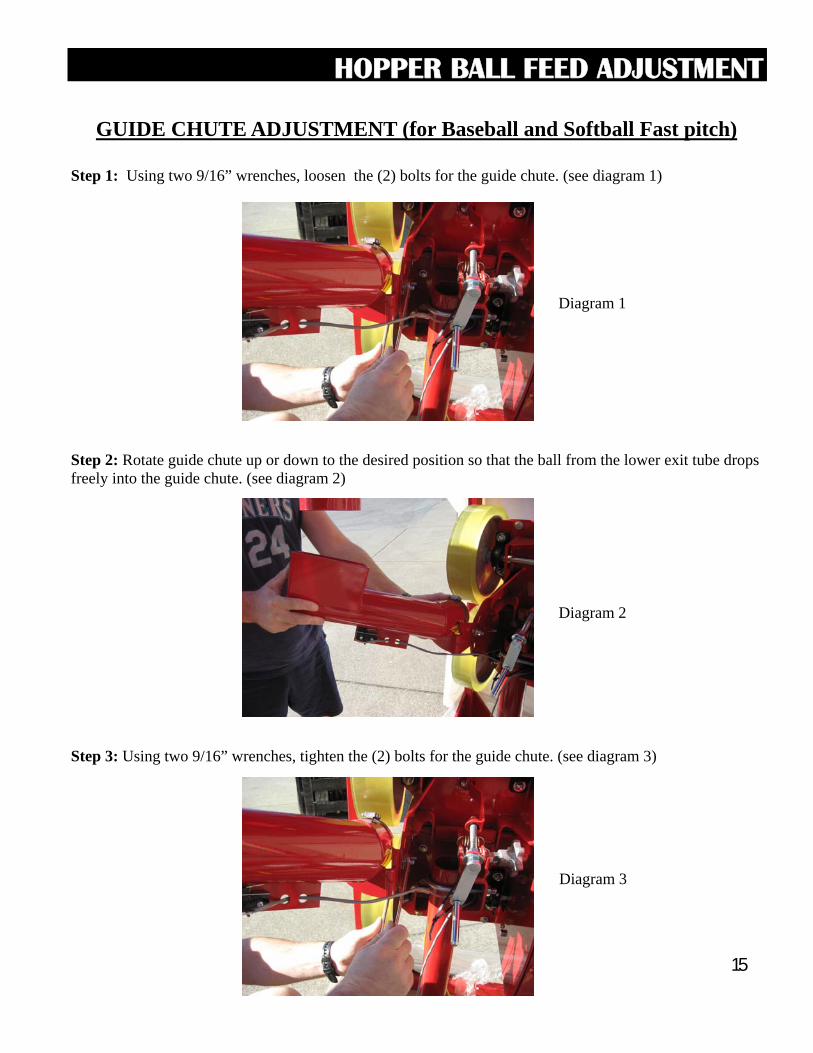
GUIDE CHUTE ADJUSTMENT (for Baseball and Softball Fast pitch)
Step 1: Using two 9/16” wrenches, loosen the (2) bolts for the guide chute. (see diagram 1)
Step 2: Rotate guide chute up or down to the desired position so that the ball from the lower exit tube drops freely into the guide chute. (see diagram 2)
Step 3: Using two 9/16” wrenches, tighten the (2) bolts for the guide chute. (see diagram 3)
Diagram 1
Diagram 2
Diagram 3
HOPPER BALL FEED ADJUSTMENT
16
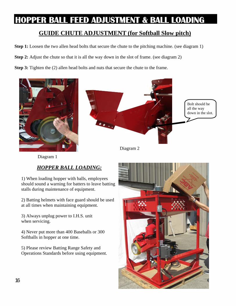
HOPPER BALL LOADING: 1) When loading hopper with balls, employees should sound a warning for batters to leave batting stalls during maintenance of equipment. 2) Batting helmets with face guard should be used at all times when maintaining equipment. 3) Always unplug power to I.H.S. unit when servicing. 4) Never put more than 400 Baseballs or 300 Softballs in hopper at one time. 5) Please review Batting Range Safety and Operations Standards before using equipment.
HOPPER BALL FEED ADJUSTMENT & BALL LOADING
GUIDE CHUTE ADJUSTMENT (for Softball Slow pitch)
Step 1: Loosen the two allen head bolts that secure the chute to the pitching machine. (see diagram 1) Step 2: Adjust the chute so that it is all the way down in the slot of frame. (see diagram 2) Step 3: Tighten the (2) allen head bolts and nuts that secure the chute to the frame.
Diagram 1
Bolt should be all the way down in the slot.
Diagram 2
17
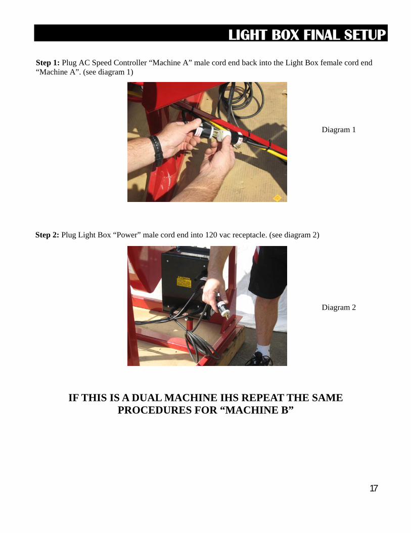
Step 1: Plug AC Speed Controller “Machine A” male cord end back into the Light Box female cord end “Machine A”. (see diagram 1)
Step 2: Plug Light Box “Power” male cord end into 120 vac receptacle. (see diagram 2)
Diagram 1
Diagram 2
LIGHT BOX FINAL SETUP
IF THIS IS A DUAL MACHINE IHS REPEAT THE SAME PROCEDURES FOR “MACHINE B”