Embed Size (px)
Citation preview
ON
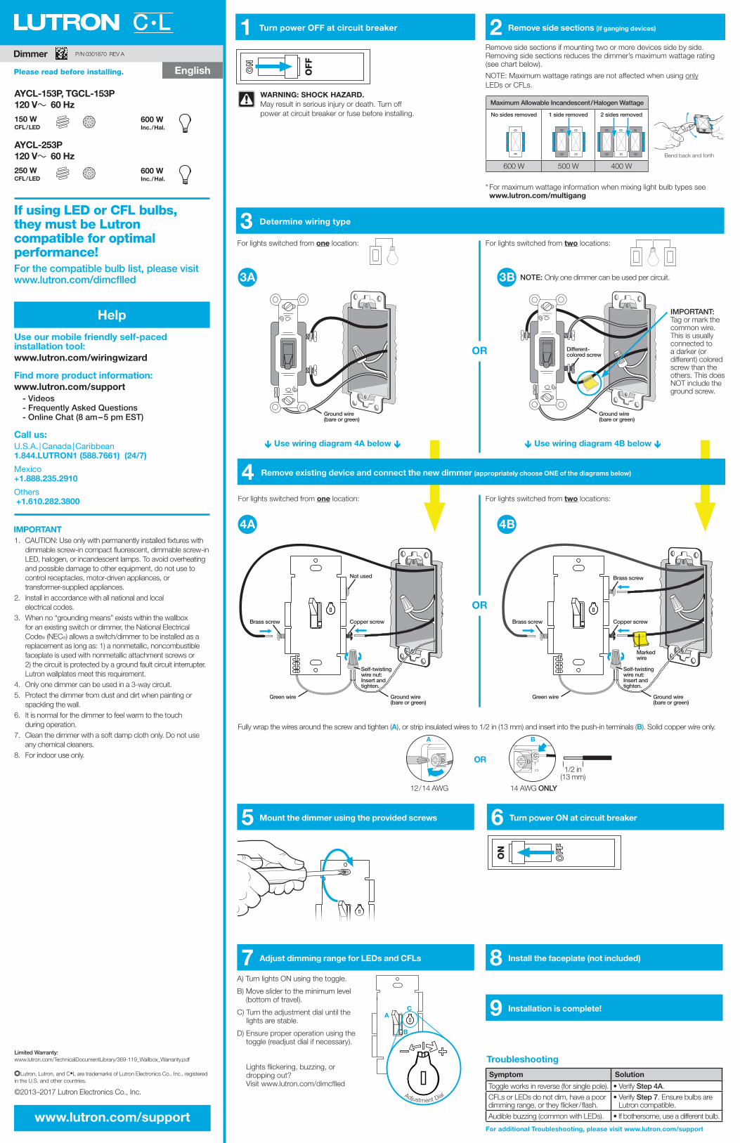
5 Mount the dimmer using the provided screws 6 Turn power ON at circuit breaker
7 Adjust dimming range for LEDs and CFLs
9 Installation is complete!
8 Install the faceplate (not included)
Dimmer
For the compatible bulb list, please visit www.lutron.com/dimcflled
If using LED or CFL bulbs, they must be Lutron
compatible for optimal performance!
C•L 2 Remove side sections (if ganging devices)
AYCL-153P, TGCL-153P 120 V~ 60 Hz
AYCL-253P 120 V~ 60 Hz
LEDDEL
LEDDEL
LFCACFL
AFC
LFCACFL
AFC
150 W CFL / LED
250 W CFL / LED
600 W Inc. / Hal.
600 W Inc. / Hal.
INC / HAL
INC / HAL
A) Turn lights ON using the toggle.
B) Move slider to the minimum level (bottom of travel).
C) Turn the adjustment dial until the lights are stable.
D) Ensure proper operation using the toggle (readjust dial if necessary). Lights flickering, buzzing, or dropping out? Visit www.lutron.com/dimcflled
Remove side sections if mounting two or more devices side by side. Removing side sections reduces the dimmer’s maximum wattage rating (see chart below).
NOTE: Maximum wattage ratings are not affected when using only LEDs or CFLs.
Fully wrap the wires around the screw and tighten (A), or strip insulated wires to 1/2 in (13 mm) and insert into the push-in terminals (B). Solid copper wire only.
12 / 14 AWG 14 AWG ONLY
OR1/2 in
(13 mm)
A B
®
Use our mobile friendly self-paced installation tool: www.lutron.com/wiringwizard
Find more product information:www.lutron.com/support
- Videos- Frequently Asked Questions- Online Chat (8 am – 5 pm EST)
Call us: U.S.A. | Canada | Caribbean 1.844.LUTRON1 (588.7661) (24/7)
Mexico +1.888.235.2910
Others +1.610.282.3800
Help
Ground wire (bare or green)
Ground wire (bare or green)
Marked wire
Ground wire (bare or green)
Not used Brass screw
Copper screwCopper screw
Self-twisting wire nut: Insert and tighten.
Self-twisting wire nut: Insert and tighten.
Different-colored screw
Brass screw Brass screw
Green wire Green wire
OFF
WARNING: SHOCK HAZARD.May result in serious injury or death. Turn off power at circuit breaker or fuse before installing.
3 Determine wiring type
1 Turn power OFF at circuit breaker
4 Remove existing device and connect the new dimmer (appropriately choose ONE of the diagrams below)
For lights switched from one location:
Use wiring diagram 4A below Use wiring diagram 4B below
For lights switched from one location:
For lights switched from two locations:
NOTE: Only one dimmer can be used per circuit.
IMPORTANT: Tag or mark the common wire. This is usually connected to a darker (or different) colored screw than the others. This does NOT include the ground screw.
For lights switched from two locations:
OR
OR
4A
Ground wire (bare or green)
IMPORTANT 4B1. CAUTION: Use only with permanently installed fixtures with
dimmable screw-in compact fluorescent, dimmable screw-in LED, halogen, or incandescent lamps. To avoid overheating and possible damage to other equipment, do not use to control receptacles, motor-driven appliances, or transformer-supplied appliances.
2. Install in accordance with all national and local electrical codes.
3. When no “grounding means” exists within the wallbox for an existing switch or dimmer, the National Electrical Code® (NEC®) allows a switch/dimmer to be installed as a replacement as long as: 1) a nonmetallic, noncombustible faceplate is used with nonmetallic attachment screws or 2) the circuit is protected by a ground fault circuit interrupter. Lutron wallplates meet this requirement.
4. Only one dimmer can be used in a 3-way circuit.5. Protect the dimmer from dust and dirt when painting or
spackling the wall.6. It is normal for the dimmer to feel warm to the touch
during operation.7. Clean the dimmer with a soft damp cloth only. Do not use
any chemical cleaners.8. For indoor use only.
www.lutron.com/support
Adjustment Dial
5
A
B
C
Maximum Allowable Incandescent / Halogen Wattage
No sides removed 1 side removed 2 sides removed
600 W 500 W 400 W
* For maximum wattage information when mixing light bulb types see www.lutron.com/multigang
Bend back and forth
3A 3B
Limited Warranty: www.lutron.com/TechnicalDocumentLibrary/369-119_Wallbox_Warranty.pdf
®Lutron, Lutron, and C•L are trademarks of Lutron Electronics Co., Inc., registered in the U.S. and other countries.
©2013–2017 Lutron Electronics Co., Inc.
English
P/N 0301870 REV A
Please read before installing. English
For additional Troubleshooting, please visit www.lutron.com/support
Symptom Solution
Toggle works in reverse (for single pole). • Verify Step 4A.CFLs or LEDs do not dim, have a poor dimming range, or they flicker / flash.
• Verify Step 7. Ensure bulbs are Lutron compatible.
Audible buzzing (common with LEDs). • If bothersome, use a different bulb.
Troubleshooting
ON
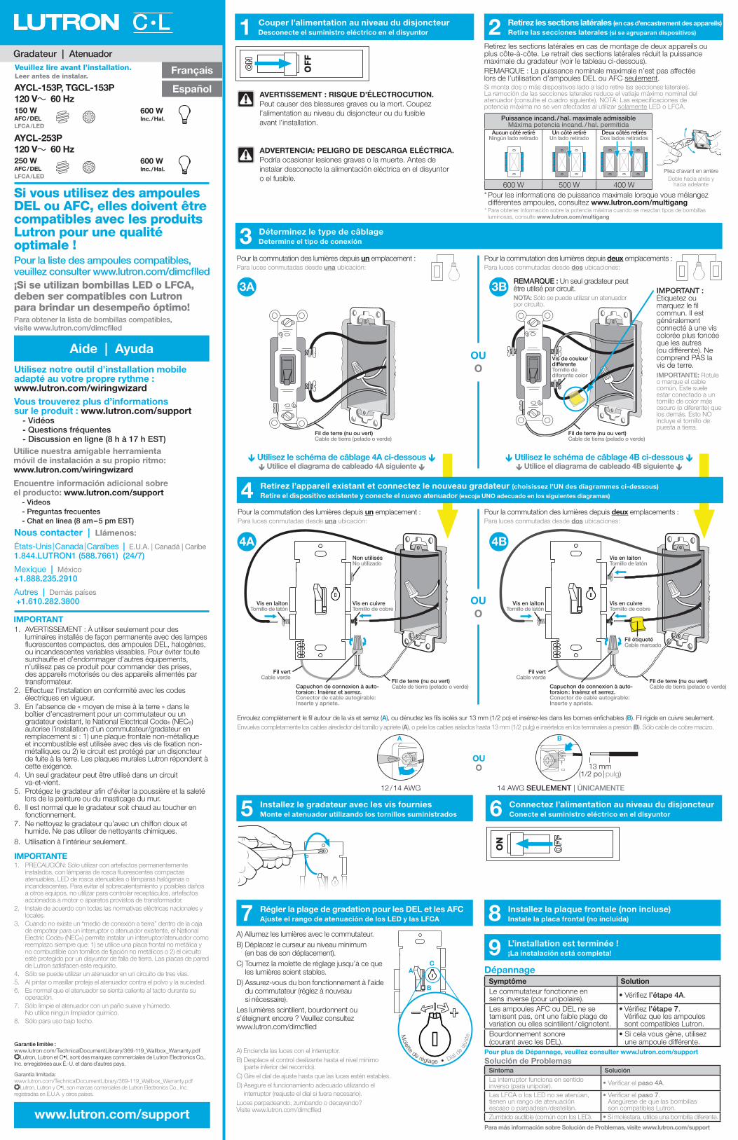
5 Installez le gradateur avec les vis fournies Monte el atenuador utilizando los tornillos suministrados 6 Connectez l’alimentation au niveau du disjoncteur
Conecte el suministro eléctrico en el disyuntor
7 Régler la plage de gradation pour les DEL et les AFC Ajuste el rango de atenuación de los LED y las LFCA
9 L’installation est terminée ! ¡La instalación está completa!
8 Installez la plaque frontale (non incluse) Instale la placa frontal (no incluida)
Gradateur | Atenuador
Pour la liste des ampoules compatibles, veuillez consulter www.lutron.com/dimcflled
Si vous utilisez des ampoules DEL ou AFC, elles doivent être compatibles avec les produits Lutron pour une qualité optimale !
2 Retirez les sections latérales (en cas d’encastrement des appareils) Retire las secciones laterales (si se agruparan dispositivos)
AYCL-153P, TGCL-153P120 V~ 60 Hz
AYCL-253P120 V~ 60 Hz
LEDDEL
LEDDEL
LFCACFL
AFC
LFCACFL
AFC
150 W AFC / DELLFCA /LED
250 WAFC / DELLFCA /LED
600 WInc. / Hal.
600 WInc. / Hal.
INC / HAL
INC / HAL
A) Allumez les lumières avec le commutateur.B) Déplacez le curseur au niveau minimum
(en bas de son déplacement).C) Tournez la molette de réglage jusqu’à ce que
les lumières soient stables.D) Assurez-vous du bon fonctionnement à l’aide
du commutateur (réglez à nouveau si nécessaire).
Les lumières scintillent, bourdonnent ou s’éteignent encore ? Veuillez consultez www.lutron.com/dimcflled
A) Encienda las luces con el interruptor.B) Desplace el control deslizante hasta el nivel mínimo
(parte inferior del recorrido).C) Gire el dial de ajuste hasta que las luces estén estables.D) Asegure el funcionamiento adecuado utilizando el
interruptor (reajuste el dial si fuera necesario).Luces parpadeando, zumbando o decayendo? Visite www.lutron.com/dimcflled
Retirez les sections latérales en cas de montage de deux appareils ou plus côte-à-côte. Le retrait des sections latérales réduit la puissance maximale du gradateur (voir le tableau ci-dessous). REMARQUE : La puissance nominale maximale n’est pas affectée lors de l’utilisation d’ampoules DEL ou AFC seulement.
Enroulez complètement le fil autour de la vis et serrez (A), ou dénudez les fils isolés sur 13 mm (1/2 po) et insérez-les dans les bornes enfichables (B). Fil rigide en cuivre seulement. Envuelva completamente los cables alrededor del tornillo y apriete (A), o pele los cables aislados hasta 13 mm (1/2 pulg) e insértelos en los terminales a presión (B). Sólo cable de cobre macizo.
12 / 14 AWG 14 AWG SEULEMENT | ÚNICAMENTE
OUO 13 mm
(1/2 po | pulg)
A B
®
Utilisez notre outil d’installation mobile adapté au votre propre rythme : www.lutron.com/wiringwizardVous trouverez plus d’informations sur le produit : www.lutron.com/support
- Vidéos- Questions fréquentes- Discussion en ligne (8 h à 17 h EST)
Nous contacter | Llámenos:
États-Unis | Canada | Caraïbes | E.U.A. | Canadá | Caribe1.844.LUTRON1 (588.7661) (24/7)
Mexique | México+1.888.235.2910
Autres | Demás países +1.610.282.3800
Aide | Ayuda
Veuillez lire avant l’installation.Leer antes de instalar.
Fil étiquetéCable marcado
Fil de terre (nu ou vert) Cable de tierra (pelado o verde)
Fil de terre (nu ou vert) Cable de tierra (pelado o verde)
Fil de terre (nu ou vert) Cable de tierra (pelado o verde)
Fil de terre (nu ou vert) Cable de tierra (pelado o verde)
Non utilisésNo utilizado
Vis en laitonTornillo de latón
Vis en cuivreTornillo de cobre
Vis en cuivreTornillo de cobre
Capuchon de connexion à auto-torsion : Insérez et serrez. Conector de cable autogirable: Inserte y apriete.
Capuchon de connexion à auto-torsion : Insérez et serrez. Conector de cable autogirable: Inserte y apriete.
Vis de couleur différenteTornillo de diferente color
Vis en laitonTornillo de latón
Vis en laitonTornillo de latón
Fil vertCable verde
Fil vertCable verde
OFF
AVERTISSEMENT : RISQUE D’ÉLECTROCUTION.Peut causer des blessures graves ou la mort. Coupez l’alimentation au niveau du disjoncteur ou du fusible avant l’installation.
3 Déterminez le type de câblage Determine el tipo de conexión
1 Couper l’alimentation au niveau du disjoncteur Desconecte el suministro eléctrico en el disyuntor
4 Retirez l’appareil existant et connectez le nouveau gradateur (choisissez l’UN des diagrammes ci-dessous) Retire el dispositivo existente y conecte el nuevo atenuador (escoja UNO adecuado en los siguientes diagramas)
Pour la commutation des lumières depuis un emplacement :Para luces conmutadas desde una ubicación:
Pour la commutation des lumières depuis un emplacement :Para luces conmutadas desde una ubicación:
Utilisez le schéma de câblage 4A ci-dessous Utilice el diagrama de cableado 4A siguiente
Utilisez le schéma de câblage 4B ci-dessous Utilice el diagrama de cableado 4B siguiente
Pour la commutation des lumières depuis deux emplacements :Para luces conmutadas desde dos ubicaciones:
Pour la commutation des lumières depuis deux emplacements :Para luces conmutadas desde dos ubicaciones:
IMPORTANT : Étiquetez ou marquez le fil commun. Il est généralement connecté à une vis colorée plus foncée que les autres (ou différente). Ne comprend PAS la vis de terre.
OUO
OUO
4A
IMPORTANT
4B
1. AVERTISSEMENT : À utiliser seulement pour des luminaires installés de façon permanente avec des lampes fluorescentes compactes, des ampoules DEL, halogènes, ou incandescentes variables vissables. Pour éviter toute surchauffe et d’endommager d’autres équipements, n’utilisez pas ce produit pour commander des prises, des appareils motorisés ou des appareils alimentés par transformateur.
2. Effectuez l’installation en conformité avec les codes électriques en vigueur.
3. En l’absence de « moyen de mise à la terre » dans le boîtier d’encastrement pour un commutateur ou un gradateur existant, le National Electrical Code® (NEC®) autorise l’installation d’un commutateur/gradateur en remplacement si : 1) une plaque frontale non-métallique et incombustible est utilisée avec des vis de fixation non-métalliques ou 2) le circuit est protégé par un disjoncteur de fuite à la terre. Les plaques murales Lutron répondent à cette exigence.
4. Un seul gradateur peut être utilisé dans un circuit va-et-vient.
5. Protégez le gradateur afin d’éviter la poussière et la saleté lors de la peinture ou du masticage du mur.
6. Il est normal que le gradateur soit chaud au toucher en fonctionnement.
7. Ne nettoyez le gradateur qu’avec un chiffon doux et humide. Ne pas utiliser de nettoyants chimiques.
8. Utilisation à l’intérieur seulement.
IMPORTANTE1. PRECAUCIÓN: Sólo utilizar con artefactos permanentemente
instalados, con lámparas de rosca fluorescentes compactas atenuables, LED de rosca atenuables o lámparas halógenas o incandescentes. Para evitar el sobrecalentamiento y posibles daños a otros equipos, no utilizar para controlar receptáculos, artefactos accionados a motor o aparatos provistos de transformador.
2. Instale de acuerdo con todas las normativas eléctricas nacionales y locales.
3. Cuando no existe un “medio de conexión a tierra” dentro de la caja de empotrar para un interruptor o atenuador existente, el National Electric Code® (NEC®) permite instalar un interruptor/atenuador como reemplazo siempre que: 1) se utilice una placa frontal no metálica y no combustible con tornillos de fijación no metálicos o 2) el circuito esté protegido por un disyuntor de falla de tierra. Las placas de pared de Lutron satisfacen este requisito.
4. Sólo se puede utilizar un atenuador en un circuito de tres vías.5. Al pintar o masillar proteja el atenuador contra el polvo y la suciedad.6. Es normal que el atenuador se sienta caliente al tacto durante su
operación.7. Sólo limpie el atenuador con un paño suave y húmedo.
No utilice ningún limpiador químico.8. Sólo para uso bajo techo.
www.lutron.com/support
Molette de réglage • Dial d
e aj
uste
5
A
B
C
* Pour les informations de puissance maximale lorsque vous mélangez différentes ampoules, consultez www.lutron.com/multigang
Pliez d’avant en arrièreDoble hacia atrás y
hacia adelante
Puissance incand. / hal. maximale admissibleMáxima potencia incand. / hal. permitida
Aucun côté retiréNingún lado retirado
Un côté retiréUn lado retirado
Deux côtés retirésDos lados retirados
600 W 500 W 400 W
3A 3B REMARQUE : Un seul gradateur peut être utilisé par circuit.
C•L
ADVERTENCIA: PELIGRO DE DESCARGA ELÉCTRICA.Podría ocasionar lesiones graves o la muerte. Antes de instalar desconecte la alimentación eléctrica en el disyuntor o el fusible.
Para obtener la lista de bombillas compatibles, visite www.lutron.com/dimcflled
¡Si se utilizan bombillas LED o LFCA, deben ser compatibles con Lutron para brindar un desempeño óptimo!
Español
Français
Utilice nuestra amigable herramienta móvil de instalación a su propio ritmo: www.lutron.com/wiringwizard
Encuentre información adicional sobre el producto: www.lutron.com/support
- Videos- Preguntas frecuentes- Chat en línea (8 am – 5 pm EST)
IMPORTANTE: Rotule o marque el cable común. Este suele estar conectado a un tornillo de color más oscuro (o diferente) que los demás. Esto NO incluye el tornillo de puesta a tierra.
NOTA: Sólo se puede utilizar un atenuador por circuito.
Pour plus de Dépannage, veuillez consulter www.lutron.com/support
Para más información sobre Solución de Problemas, visite www.lutron.com/support
Si monta dos o más dispositivos lado a lado retire las secciones laterales. La remoción de las secciones laterales reduce el vatiaje máximo nominal del atenuador (consulte el cuadro siguiente). NOTA: Las especificaciones de potencia máxima no se ven afectadas al utilizar solamente LED o LFCA.
* Para obtener información sobre la potencia máxima cuando se mezclan tipos de bombillas luminosas, consulte www.lutron.com/multigang
Garantie limitée : www.lutron.com/TechnicalDocumentLibrary/369-119_Wallbox_Warranty.pdf
®Lutron, Lutron et C•L sont des marques commerciales de Lutron Electronics Co., Inc. enregistrées aux É.-U. et dans d’autres pays.
Garantía limitada: www.lutron.com/TechnicalDocumentLibrary/369-119_Wallbox_Warranty.pdf
®Lutron, Lutron y C•L son marcas comerciales de Lutron Electronics Co., Inc. registradas en E.U.A. y otros países.
Symptôme SolutionLe commutateur fonctionne en sens inverse (pour unipolaire). • Vérifiez l’étape 4A.
Les ampoules AFC ou DEL ne se tamisent pas, ont une faible plage de variation ou elles scintillent / clignotent.
• Vérifiez l’étape 7. Vérifiez que les ampoules sont compatibles Lutron.
Bourdonnement sonore (courant avec les DEL).
• Si cela vous gêne, utilisez une ampoule différente.
Síntoma SoluciónLa interruptor funciona en sentido inverso (para unipolar). • Verificar el paso 4A.
Las LFCA o los LED no se atenúan, tienen un rango de atenuación escaso o parpadean /destellan.
• Verificar el paso 7. Asegúrese de que las bombillas son compatibles Lutron.
Zumbido audible (común con los LED). • Si molestara, utilice una bombilla diferente.
Dépannage
Solución de Problemas