Embed Size (px)
Citation preview

© 2016 www.pemnet.com 1
Oculus Rift
January 2017
by Jon Brunk
PennEngineering®
Title Slide – Do Not Remove Enter the Name and Model of the object being torn down.
If it is CSI, leave the Confidential note.
If it is a teardown, remove the confidential note, delete the CSI logo.

© 2016 www.pemnet.com 2
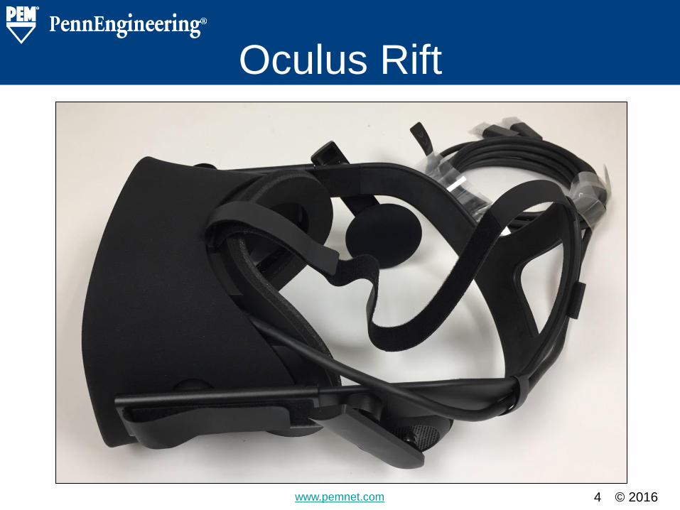
Oculus Rift
Introductory Slide – Do Not Remove Enter the name of the object being torn down
and a picture of the assembled product.

© 2016 www.pemnet.com 3
Details & Findings
Pictures and Description of the
Oculus Rift and our disassembly
process.
Section Heading Slide – Do Not Remove Enter the Name of the object being torn down.
© 2016 www.pemnet.com 4
Oculus Rift
Detail Slide – Copy and use for details. Title various slides to correspond with different
portions of the object being torn down (e.g.
Case, charging station, etc…)

© 2016 www.pemnet.com 5
Oculus Rift
Detail Slide – Copy and use for details. Title various slides to correspond with different
portions of the object being torn down (e.g.
Case, charging station, etc…)

© 2016 www.pemnet.com 6
Facemask Cushion
• Cushion simply slides into
place
• Easy to remove and insert
Detail Slide – Copy and use for details. Title various slides to correspond with different
portions of the object being torn down (e.g.
Case, charging station, etc…)

© 2016 www.pemnet.com 7
Oculus Rift
Detail Slide – Copy and use for details. Title various slides to correspond with different
portions of the object being torn down (e.g.
Case, charging station, etc…)

© 2016 www.pemnet.com 8
Headphone
Detail Slide – Copy and use for details. Title various slides to correspond with different
portions of the object being torn down (e.g.
Case, charging station, etc…)

© 2016 www.pemnet.com 9
Headphone
• Round metal cover held
by light adhesive
• Three openings for stud
and contact pins to pass
through
Detail Slide – Copy and use for details. Title various slides to correspond with different
portions of the object being torn down (e.g.
Case, charging station, etc…)

© 2016 www.pemnet.com 10
Headphone
• Free spinning internally
threaded fastener
• Threads onto the stud
installed in headphone
• Chamfered bottom sits in
a countersunk hole in the
head strap
Detail Slide – Copy and use for details. Title various slides to correspond with different
portions of the object being torn down (e.g.
Case, charging station, etc…)

© 2016 www.pemnet.com 11
Headphone
• Two screws attach metal
ring over a plastic
housing into plastic boss
• Metal ring lets the
housing rotate
Detail Slide – Copy and use for details. Title various slides to correspond with different
portions of the object being torn down (e.g.
Case, charging station, etc…)

© 2016 www.pemnet.com 12
Headphone
• End cap snaps into place
• Prevents rest of assembly from falling out
Detail Slide – Copy and use for details. Title various slides to correspond with different
portions of the object being torn down (e.g.
Case, charging station, etc…)

© 2016 www.pemnet.com 13
Headphone
• Headphone pedestal
fastened by 1 shoulder
screw
• Pedestal snaps into
headphone
Detail Slide – Copy and use for details. Title various slides to correspond with different
portions of the object being torn down (e.g.
Case, charging station, etc…)

© 2016 www.pemnet.com 14
Headphone
• Headphone assembly
partially disassembled
• Headphone rotates on a
pedestal made up of five
components
Detail Slide – Copy and use for details. Title various slides to correspond with different
portions of the object being torn down (e.g.
Case, charging station, etc…)

© 2016 www.pemnet.com 15
Headphone
• Threaded boss to attach
the headphone assembly
Detail Slide – Copy and use for details. Title various slides to correspond with different
portions of the object being torn down (e.g.
Case, charging station, etc…)

© 2016 www.pemnet.com 16
Headphone
• Stud has a knurled head
• Pressed (or molded) into
plastic housing
• Connector pins press fit
in plastic
Detail Slide – Copy and use for details. Title various slides to correspond with different
portions of the object being torn down (e.g.
Case, charging station, etc…)

© 2016 www.pemnet.com 17
Headphone
• Hinging mechanism in
headphone
• Allows headphone to
retract from user’s ear
• 6 hinge pins and 3
springs in assembly
Detail Slide – Copy and use for details. Title various slides to correspond with different
portions of the object being torn down (e.g.
Case, charging station, etc…)

© 2016 www.pemnet.com 18
Facemask Cover
Detail Slide – Copy and use for details. Title various slides to correspond with different
portions of the object being torn down (e.g.
Case, charging station, etc…)

© 2016 www.pemnet.com 19
Facemask Cover
• 6 screws – 2 top and 4 bottom hold cover
over inside of device (in deep recesses)
Detail Slide – Copy and use for details. Title various slides to correspond with different
portions of the object being torn down (e.g.
Case, charging station, etc…)

© 2016 www.pemnet.com 20
Facemask Cover
Detail Slide – Copy and use for details. Title various slides to correspond with different
portions of the object being torn down (e.g.
Case, charging station, etc…)
© 2016 www.pemnet.com 21
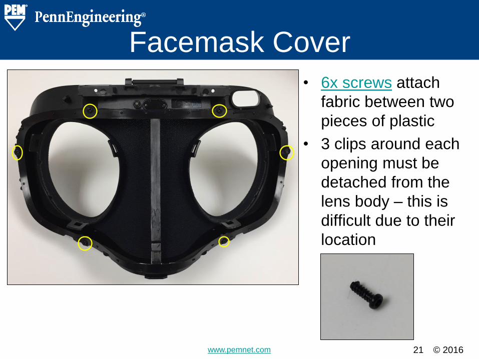
Facemask Cover
• 6x screws attach
fabric between two
pieces of plastic
• 3 clips around each
opening must be
detached from the
lens body – this is
difficult due to their
location
Detail Slide – Copy and use for details. Title various slides to correspond with different
portions of the object being torn down (e.g.
Case, charging station, etc…)
© 2016 www.pemnet.com 22
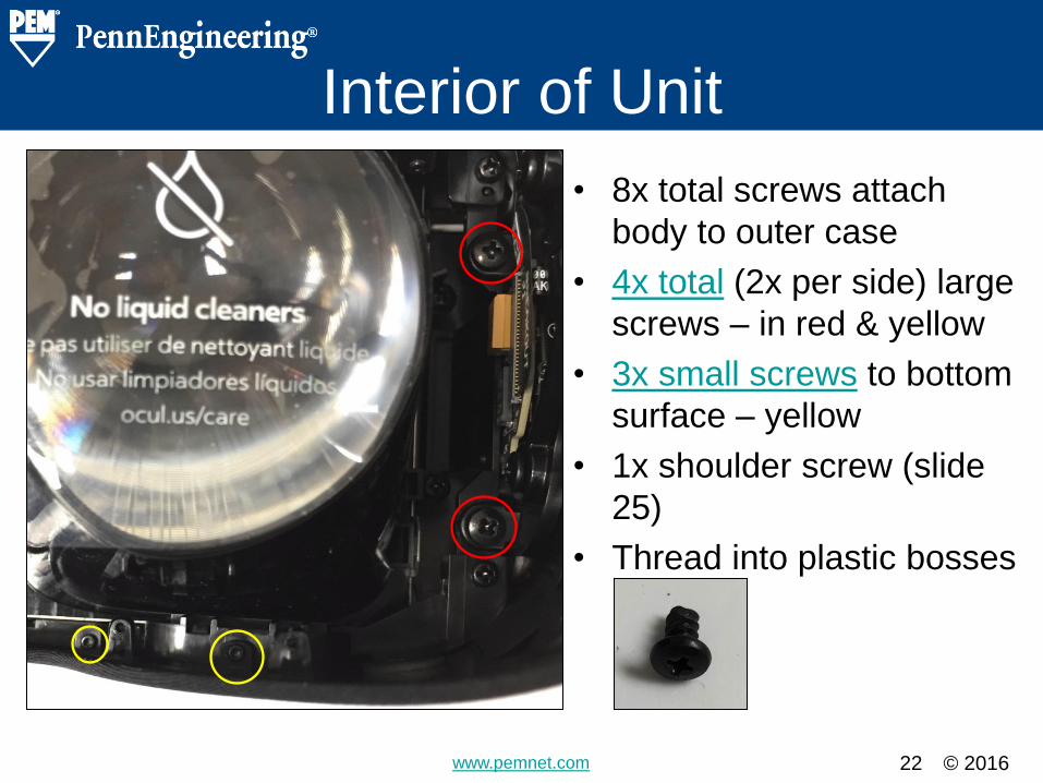
Interior of Unit
• 8x total screws attach
body to outer case
• 4x total (2x per side) large
screws – in red & yellow
• 3x small screws to bottom
surface – yellow
• 1x shoulder screw (slide
25)
• Thread into plastic bosses
Detail Slide – Copy and use for details. Title various slides to correspond with different
portions of the object being torn down (e.g.
Case, charging station, etc…)
© 2016 www.pemnet.com 23
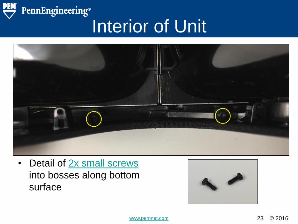
Interior of Unit
• Detail of 2x small screws
into bosses along bottom
surface
Detail Slide – Copy and use for details. Title various slides to correspond with different
portions of the object being torn down (e.g.
Case, charging station, etc…)

© 2016 www.pemnet.com 24
Interior of Unit
• 1x shoulder screw above
PC board
• Threads into boss in front
surface
• Passes thru a rectangular
opening in outer case
Detail Slide – Copy and use for details. Title various slides to correspond with different
portions of the object being torn down (e.g.
Case, charging station, etc…)

© 2016 www.pemnet.com 25
Lens Adjustment
• Lenses adjust with a knob
on bottom
• Knob has two press fit pins
with a spring on each
• Grooves on knob push
rack and pinion gears
Detail Slide – Copy and use for details. Title various slides to correspond with different
portions of the object being torn down (e.g.
Case, charging station, etc…)

© 2016 www.pemnet.com 26
Interior of Unit
• Main body and outer case
attached by 3 flex cables
Detail Slide – Copy and use for details. Title various slides to correspond with different
portions of the object being torn down (e.g.
Case, charging station, etc…)

© 2016 www.pemnet.com 27
Small Side PC Board
• 2x screws attach a metal
cover over PCB and flex
cables
• Also has two molded
alignment pins
Detail Slide – Copy and use for details. Title various slides to correspond with different
portions of the object being torn down (e.g.
Case, charging station, etc…)

© 2016 www.pemnet.com 28
Small Side PC Board
Detail Slide – Copy and use for details. Title various slides to correspond with different
portions of the object being torn down (e.g.
Case, charging station, etc…)

© 2016 www.pemnet.com 29
Small Side PC Board
• PC Board attached to
head strap by three flex
cables
• PC Board attached to
device with two screws
(circled in yellow)
• This PCB also has a
cable attached at top and
bottom
Detail Slide – Copy and use for details. Title various slides to correspond with different
portions of the object being torn down (e.g.
Case, charging station, etc…)

© 2016 www.pemnet.com 30
Disconnected from Case
Detail Slide – Copy and use for details. Title various slides to correspond with different
portions of the object being torn down (e.g.
Case, charging station, etc…)

© 2016 www.pemnet.com 31
Top PC Board • Large PCB running across the top of the unit.
• Two attachment points – one for each lens.
• PCB sits inside a plastic frame.
• Frame is held by 2 screws (yellow)
Detail Slide – Copy and use for details. Title various slides to correspond with different
portions of the object being torn down (e.g.
Case, charging station, etc…)

© 2016 www.pemnet.com 32
Top PC Board
Detail Slide – Copy and use for details. Title various slides to correspond with different
portions of the object being torn down (e.g.
Case, charging station, etc…)

© 2016 www.pemnet.com 33
Top PC Board
• PC Board attached to plastic frame
with 6 screws (yellow)
• One additional screw holds a
bracket around the HDMI port (red)
Detail Slide – Copy and use for details. Title various slides to correspond with different
portions of the object being torn down (e.g.
Case, charging station, etc…)

© 2016 www.pemnet.com 34
Top PC Board
• Hardware around HDMI port
• D-shaped boss
• Two molded alignment pins
Detail Slide – Copy and use for details. Title various slides to correspond with different
portions of the object being torn down (e.g.
Case, charging station, etc…)

© 2016 www.pemnet.com 35
Top PC Board
Detail Slide – Copy and use for details. Title various slides to correspond with different
portions of the object being torn down (e.g.
Case, charging station, etc…)

© 2016 www.pemnet.com 36
Top PC Board Frame
• All bosses and alignment
points on PCB frame
• Additionally there are two
snap in locations to
secure the board (blue)
Detail Slide – Copy and use for details. Title various slides to correspond with different
portions of the object being torn down (e.g.
Case, charging station, etc…)

© 2016 www.pemnet.com 37
Front Cover Attachment
• 4x screws along bottom
of device
• Thread into bosses in
front cover
Detail Slide – Copy and use for details. Title various slides to correspond with different
portions of the object being torn down (e.g.
Case, charging station, etc…)

© 2016 www.pemnet.com 38
Front Cover Attachment
• Bracket that holds lenses is
attached to front cover by a
total of 6 screws:
– 2 per side (yellow)
– 1 at top (red) and bottom
Detail Slide – Copy and use for details. Title various slides to correspond with different
portions of the object being torn down (e.g.
Case, charging station, etc…)
© 2016 www.pemnet.com 39
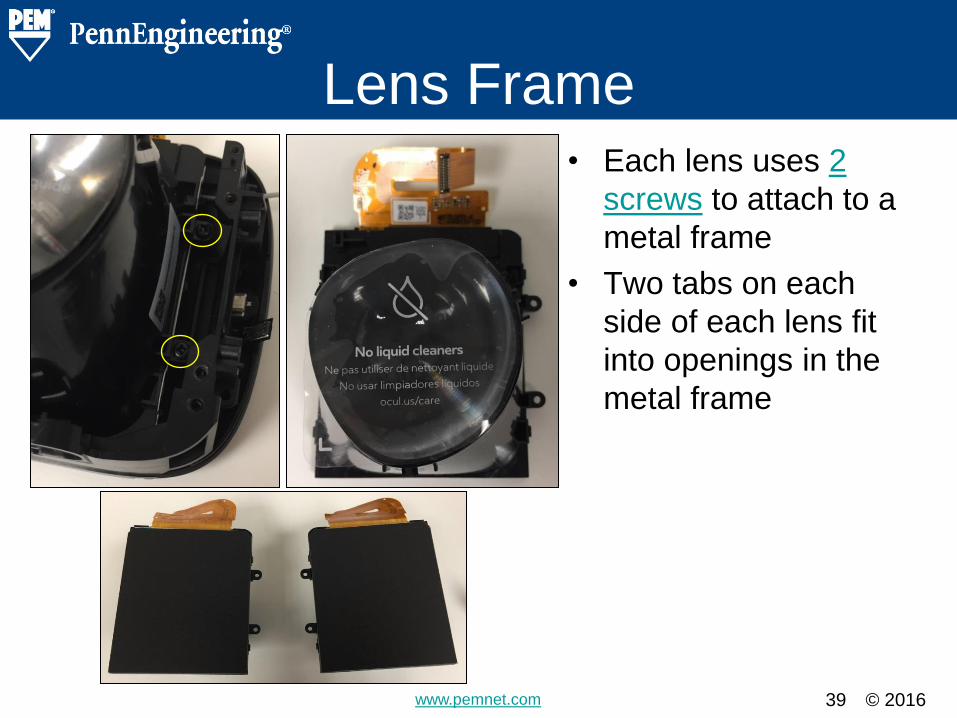
Lens Frame
• Each lens uses 2
screws to attach to a
metal frame
• Two tabs on each
side of each lens fit
into openings in the
metal frame
Detail Slide – Copy and use for details. Title various slides to correspond with different
portions of the object being torn down (e.g.
Case, charging station, etc…)

© 2016 www.pemnet.com 40
Lens Frame
Detail Slide – Copy and use for details. Title various slides to correspond with different
portions of the object being torn down (e.g.
Case, charging station, etc…)

© 2016 www.pemnet.com 41
Lens Frame
• With front cover removed
Detail Slide – Copy and use for details. Title various slides to correspond with different
portions of the object being torn down (e.g.
Case, charging station, etc…)
© 2016 www.pemnet.com 42
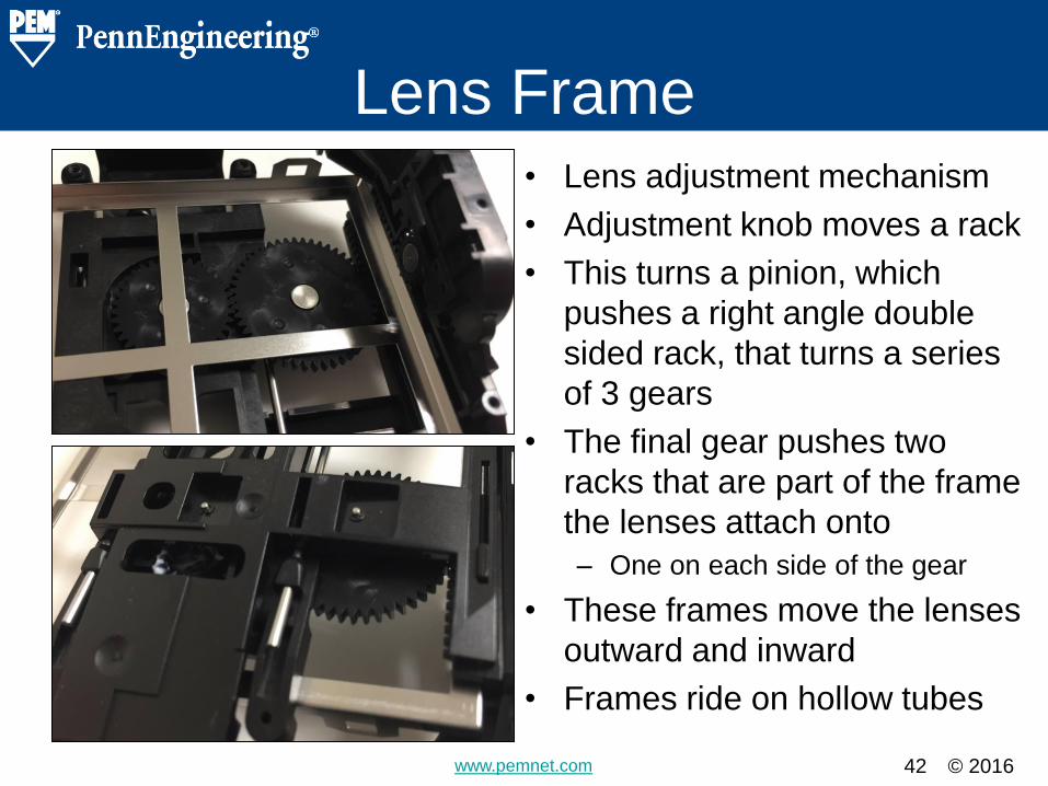
Lens Frame
• Lens adjustment mechanism
• Adjustment knob moves a rack
• This turns a pinion, which
pushes a right angle double
sided rack, that turns a series
of 3 gears
• The final gear pushes two
racks that are part of the frame
the lenses attach onto
– One on each side of the gear
• These frames move the lenses
outward and inward
• Frames ride on hollow tubes
Detail Slide – Copy and use for details. Title various slides to correspond with different
portions of the object being torn down (e.g.
Case, charging station, etc…)

© 2016 www.pemnet.com 43
Lens Frame
• The three sets of gears
are attached with a pin
and e-clip
Detail Slide – Copy and use for details. Title various slides to correspond with different
portions of the object being torn down (e.g.
Case, charging station, etc…)
© 2016 www.pemnet.com 44
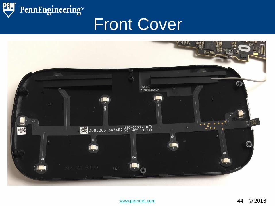
Front Cover
Detail Slide – Copy and use for details. Title various slides to correspond with different
portions of the object being torn down (e.g.
Case, charging station, etc…)

© 2016 www.pemnet.com 45
Outer Case
Detail Slide – Copy and use for details. Title various slides to correspond with different
portions of the object being torn down (e.g.
Case, charging station, etc…)

© 2016 www.pemnet.com 46
Head Strap
• Head strap is
fastened by one
screw
• Inner and outer
halves snap
together
Detail Slide – Copy and use for details. Title various slides to correspond with different
portions of the object being torn down (e.g.
Case, charging station, etc…)

© 2016 www.pemnet.com 47
Head Strap
• Outside surface of
headphone attachment
• Two recesses for
electrical connection
with headphone
• Inside surface of
headphone attachment
• Free spinning flat head
internally threaded
fastener
Detail Slide – Copy and use for details. Title various slides to correspond with different
portions of the object being torn down (e.g.
Case, charging station, etc…)

© 2016 www.pemnet.com 48
Head Strap
• Two screws fasten the springs to the strap
• Thread into metal boss
Detail Slide – Copy and use for details. Title various slides to correspond with different
portions of the object being torn down (e.g.
Case, charging station, etc…)
© 2016 www.pemnet.com 49
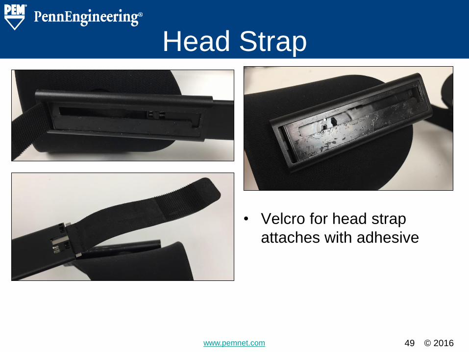
Head Strap
• Velcro for head strap
attaches with adhesive
Detail Slide – Copy and use for details. Title various slides to correspond with different
portions of the object being torn down (e.g.
Case, charging station, etc…)

© 2016 www.pemnet.com 50
Head Strap
Detail Slide – Copy and use for details. Title various slides to correspond with different
portions of the object being torn down (e.g.
Case, charging station, etc…)
• 4 screws attach a hinging
mechanism inside the
case
• Microphone covered by
tape (bottom right)
© 2016 www.pemnet.com 51
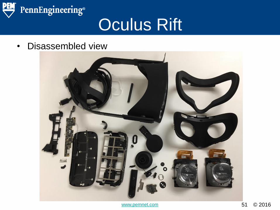
Oculus Rift • Disassembled view
Disassembled – Do Not Remove Enter the name of the object being torn down
and a picture of the completely disassembled
product.
© 2016 www.pemnet.com 52
Fastener Summary
A total of 74 fasteners were found
in the device
Section Heading Slide – Do Not Remove

© 2016 www.pemnet.com 53
Fastener Summary
Detail Slide – Copy and use for details. Create a table of the fasteners found in the teardown.
Note thread sizes, lengths, drivers, etc. Multiple pages
can be used for different style fasteners
• 2x Free Spinning Nut
– Slide 10
– 1 per side
– Attach headphone to strap
– Slot Drive
– M3 Thread
– Chamfered Head
– 11 mm Outer Diameter
– 3.9 mm Height
– 4.25 mm Barrel Diameter
• 4x Screws
– Slide 11
– Inside headphone assembly
– #0 Phillips Drive
– Thin Head
– M1.4 Thread
– 4 mm Overall Length
– 0.5 mm Thick Head
– 2.8 mm Head Diameter

© 2016 www.pemnet.com 54
Fastener Summary
Detail Slide – Copy and use for details. Create a table of the fasteners found in the teardown.
Note thread sizes, lengths, drivers, etc. Multiple pages
can be used for different style fasteners
• 2x Shoulder Screw
– Slide 13
– 1 per Headphone
– T7 Torx Drive
– Cheese Head
– M1.8 Thread
– 12 mm Overall Length
– 2 mm Thick Head
– 5 mm Long Shoulder
– 5 mm Head Diameter
– 3 mm Shoulder Diameter
• 2x Broach Stud
– Slide 16
– Inside headphone assembly
– Knurled Head
– M3 Thread

© 2016 www.pemnet.com 55
Fastener Summary
Detail Slide – Copy and use for details. Create a table of the fasteners found in the teardown.
Note thread sizes, lengths, drivers, etc. Multiple pages
can be used for different style fasteners
• 26x Screws – 6 locations
– Slide 19, Slide 21, Slide 22,
Slide 27, Slide 29, Slide 33
– 3IP Torx Plus
– Pan Head
– M1.4 Thread
– 4.5 mm Overall Length
– 0.7 mm Thick Head
– 2.3 mm Head Diameter
• 12x Screws – 2 locations
– Slide 22, Slide 50
– #1 Phillips Drive
– Pan Head
– M3 Thread
– 6.25 mm Overall Length
– 1.5 mm Thick Head
– 5.5 mm Head Diameter

© 2016 www.pemnet.com 56
Fastener Summary
Detail Slide – Copy and use for details. Create a table of the fasteners found in the teardown.
Note thread sizes, lengths, drivers, etc. Multiple pages
can be used for different style fasteners
• 1x Shoulder Screw
– Slide 24
– #1 Phillips Drive
– Cheese Head
– M1.4 Thread
– 5.4 mm Overall Length
– 1 mm Thick Head
– 1.7 mm Long Shoulder
– 3.5 mm Head Diameter
– 2.4 mm Shoulder Diameter
• 12x Screws – 3 locations
– Slide 31, Slide 38, Slide 39
– #1 Phillips Drive
– Pan Head
– M2 Thread
– 5 mm Overall Length
– 1.3 mm Thick Head
– 3.7 mm Head Diameter

© 2016 www.pemnet.com 57
Fastener Summary
Detail Slide – Copy and use for details. Create a table of the fasteners found in the teardown.
Note thread sizes, lengths, drivers, etc. Multiple pages
can be used for different style fasteners
• 4x Screws
– Slide 37
– #00 Phillips Drive
– Pan Head
– M1 Thread
– 2.75 mm Overall Length
– 0.5 mm Thick Head
– 1.5 mm Head Diameter
• 3x E-clips
– Slide 43
– 1 mm Pin Diameter
– 1.5 mm Shoulder Diameter
– 4.5 mm Head Diameter
– 0.75 mm Thick Head
– 2.75 mm Shoulder Length
– 7.25 mm Overall Length

© 2016 www.pemnet.com
• 4x Screws
– Slide 48
– 2IP Torx Plus
– Pan Head
– M1.6 Thread
– 2.35 mm Overall Length
– 0.6 mm Thick Head
– 2.35 mm Head Diameter
58
Fastener Summary
Detail Slide – Copy and use for details. Create a table of the fasteners found in the teardown.
Note thread sizes, lengths, drivers, etc. Multiple pages
can be used for different style fasteners
• 2x Screws
– Slide 46
– #0 Phillips Drive
– Pan Head
– M1.6 Thread
– 3 mm Overall Length
– 0.5 mm Thick Head
– 2.7 mm Head Diameter

© 2016 www.pemnet.com 59
Alternate Solutions
PennEngineering® recommendations
of alternate hardware and cost savings
opportunities.
Section Heading Slide – Do Not Remove

© 2016 www.pemnet.com 60
Spinning Clinch Standoff
• Self-Clinching Spinning
Standoff
• Would require a straight
thru-hole only
• Would permanently install
and would be freely
spinning after installation
Detail Slide – Copy and use for details. Note any new solutions (PEM or non-PEM).
Highlight the advantages and disadvantages
of each.

© 2016 www.pemnet.com 61
Broach Stud
• Type KFH broaching studs are designed to
press into a plastic hole.
• Straight thru hole is all that is required.
• Part can be modified to fit a wide variety of
applications.
• Available in aluminum for weight reduction
Detail Slide – Copy and use for details. Note any new solutions (PEM or non-PEM).
Highlight the advantages and disadvantages
of each.

© 2016 www.pemnet.com 62
TackSert® Pins
• Broaching TackSert® Pins can
permanently install into plastic
materials.
• The fastener can be designed with a
shoulder for a gear to rotate around.
• Can replace an e-clip and pin with a
one piece fastener.
• Made from high strength Aluminum
for weight reduction.
Detail Slide – Copy and use for details. Note any new solutions (PEM or non-PEM).
Highlight the advantages and disadvantages
of each.

© 2016 www.pemnet.com 63
SpotFast® Fasteners
The SFK SpotFast® can clinch into metal and broach into
plastic. It can permanently join two dissimilar materials as
in the above situation. In this case it would replace the
bent metal with a flush fastener.
Detail Slide – Copy and use for details. Note any new solutions (PEM or non-PEM).
Highlight the advantages and disadvantages
of each.

© 2016 www.pemnet.com 64
TackSert® Pins
Example of three locations
that could replace screws
with press-in TackSert®
Pins for permanent
installation.
Made from aluminum, to
save weight, or stainless
steel.
Detail Slide – Copy and use for details. Note any new solutions (PEM or non-PEM).
Highlight the advantages and disadvantages
of each.
Plastic Frame PC Board to Frame Facemask

© 2016 www.pemnet.com 65
Interference Pins
PennEngineering is able to cold form a wide variety of pins
to tight dimensional tolerances from different materials.
Detail Slide – Copy and use for details. Note any new solutions (PEM or non-PEM).
Highlight the advantages and disadvantages
of each.

© 2016 www.pemnet.com 66
microPEM® Screws
PennEngineering manufactures a
wide range of micro screws. These
can be made from high strength,
lightweight aluminum with
dimensions and features per
customer requirements.
Detail Slide – Copy and use for details. Note any new solutions (PEM or non-PEM).
Highlight the advantages and disadvantages
of each.

© 2016 www.pemnet.com 67
Conclusions and Summary
Section Heading Slide – Do Not Remove

© 2016 www.pemnet.com 68
Oculus Rift
The Oculus Rift is a lightweight device that utilizes
plastic molding and light metals. Almost all
fasteners thread into plastic bosses using high
helix screws. Since it is a wearable, weight is very
important, hence why the primary use of plastic
wherever possible. Most of the components of the
Oculus Rift are straightforward enough to
disassemble if required.
Detail Slide – Copy and use for details. Summarize the findings and alternate
solutions.