Embed Size (px)
DESCRIPTION
! www.alphasondesigns.com S E R I E S BEFORE STARTING THIS ASSEMBLY PLEASE TAKE TIME TO FAMILIARISE YOURSELF WITH THE COMPONENTS LISTED ON THE BACK PAGE Alphason Designs Limited Alphason House, Bolton Road, Atherton, Greater Manchester M46 9AW UK Tel: +44 (0)1942 885600 Fax: +44 (0)1942 876955 Email: [email protected] In addition to the tools supplied, a cross-head screwdriver and flat- head screwdriver are also required to complete this assembly. 04 10/07 issue
Citation preview
04 10/07issue
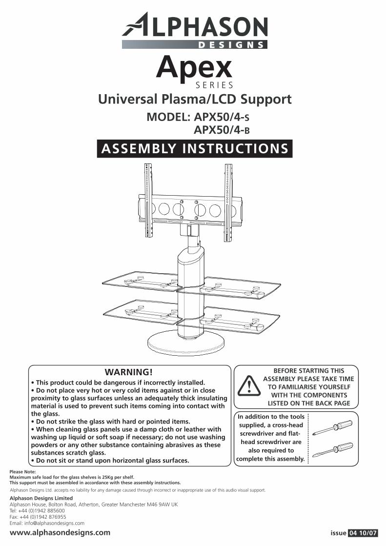
Universal Plasma/LCD SupportMODEL: APX50/4-S
APX50/4-B
ASSEMBLY INSTRUCTIONS
Alphason Designs LimitedAlphason House, Bolton Road, Atherton, Greater Manchester M46 9AW UKTel: +44 (0)1942 885600Fax: +44 (0)1942 876955Email: [email protected]
www.alphasondesigns.com
Alphason Designs Ltd. accepts no liability for any damage caused through incorrect or inappropriate use of this audio visual support.
Please Note:Maximum safe load for the glass shelves is 25Kg per shelf.This support must be assembled in accordance with these assembly instructions.
!BEFORE STARTING THIS
ASSEMBLY PLEASE TAKE TIMETO FAMILIARISE YOURSELFWITH THE COMPONENTS
LISTED ON THE BACK PAGE
WARNING!
ApexS E R I E S
• This product could be dangerous if incorrectly installed.• Do not place very hot or very cold items against or in close proximity to glass surfaces unless an adequately thick insulating material is used to prevent such items coming into contact with the glass.• Do not strike the glass with hard or pointed items.• When cleaning glass panels use a damp cloth or leather with washing up liquid or soft soap if necessary; do not use washing powders or any other substance containing abrasives as these substances scratch glass.• Do not sit or stand upon horizontal glass surfaces.
In addition to the tools supplied, a cross-head screwdriver and flat-head screwdriver are
also required to complete this assembly.

Place base panel upside down on a suitable
clean surface to avoid any damage (Fig. 1a).
Insert roller glides into holes in base panel.
Ensure that these are seated fully before
proceeding.
Attach base panel assembly to main
column assembly using small M8
washers and M8 screws . Ensure
these are fully tightened with allen key
before proceeding to the next stage.
STAGE 1
•
•
•
Insert support bars carefully
through main column, ensuring
that the flat portion of the bar
faces uppermost.
Ensure threaded holes in
support bar align correctly with
corresponding holes in support
bar mouldings (see fig. 3a).
STAGE 3
•
•
Insert support bar mouldings into large round
holes in main column. Ensure that the two small
holes in the mouldings align correctly with the
corresponding holes in main column.
Use screws to finally secure mouldings to main
column.
STAGE 2
•
•
04 10/07issue
1.
2.
3.
1a.
x4 x4
dd
D
D
D
w
w
w
w
w
EE
dddd
BB
A
A
C
C
v v
v
3a.
x16
w

Screw support bar fixing screw through
support bar moulding and into support bar using
small allen key.
Assemble shelf support arms over support
bars and firmly onto support bar
mouldings .
Insert support bar end-plugs firmly into shelf
support arms and secure with fixing
screw again using small allen key.
Push-fit tube end plugs onto support bar
end plugs.
STAGE 4
•
•
•
•
Attach swivel assembly to top die-casting
using M6 screws . Ensure screws are fully
tightened.
STAGE 6
•
STAGE 5•
•
•
Attach metal shelf supports to shelf
support arms using screws .
Attach glass shelves to shelf support
bars using M8 screws .
Only fully tighten once all screws
have been installed.
x16
x404 10/07issue
4.
5.
6.
x
x
x
x x x
y
LL L
x16
bb
x16
w
J
J
F bb
bb
K
KK
y
y
y
J
w
w
w
F
H
H
w
F
E
E
D
G
G

Attach screen mounting plate to swivel assembly
using M8 bolts , small M8 washers and
nuts .
STAGE 7
•
Assemble vertical adjustment screw into vertical adjustment bracket . Ensure adjustment screw
is screwed into bracket all the way.
STAGE 9
•
STAGE 8•
•
Attach vertical screen mounting brackets at
desired height to rear of television using suitable
screws & washers from fixing pack .
It may be necessary to use plastic spacers (supplied
with fixing pack) between screen mounting bracket
and rear of television (as shown to the right).
STAGE 10•
•
Insert vertical adjustment brackets
into vertical screen mounting
brackets at desired height. Secure
using M6 screws , and dome
nuts .
Fully tighten top screws & nuts,
however leave bottom screws &
nuts finger tight.
04 10/07issue
7.
8.
9.
10.
jj
z
z
z
ee
ee
ee
ff ff
MM
N
NN
PP
Q
Q
dddd
dd
Plastic spacers(optional)
aa aa
x8 x4 x4
x4
dd ee ff
z
x4
aa
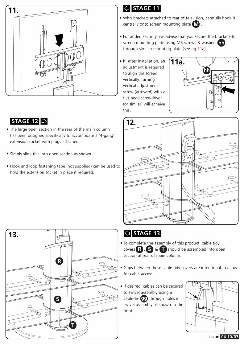
To complete the assembly of this product, cable tidy
covers , & should be assembled into open
section at rear of main column.
Gaps between these cable tidy covers are intentional to allow
for cable access.
With brackets attached to rear of television, carefully hook it
centrally onto screen mounting plate .
For added security, we advise that you secure the brackets to
screen mounting plate using M6 screws & washers
through slots in mounting plate (see fig 11a).
If, after installation, an
adjustment is required
to align the screen
vertically, turning
vertical adjustment
screw (arrowed) with a
flat-head screwdriver
(or similar) will acheive
this.
STAGE 11
•
•
•
STAGE 12•
•
•
The large open section in the rear of the main column
has been designed specifically to accomodate a ‘4-gang’
extension socket with plugs attached.
Simply slide this into open section as shown.
Hook and loop fastening tape (not supplied) can be used to
hold the extension socket in place if required.
STAGE 13
•
•
•
04 10/07issue
11.
12.
13.
hh
hh
R
R
S
S
T
T
M
If desired, cables can be secured
to swivel assembly using a
cable-tie through holes in
swivel assembly as shown to the
right.
gg
11a.

A
DESCRIPTION QTY PACKED BYCOMPONENT
MODEL: APX50/4-S & APX50/4-B
CERTIFICATE OF CONFORMITY
04 09/07issue
1MAIN COLUMN ASSEMBLY
1BASE PANEL
6ROLLER GLIDE
4SUPPORT BAR MOULDING
2SUPPORT BAR
4SHELF SUPPORT ARMS
4SUPPORT BAR END PLUG
4TUBE END PLUG
8METAL SHELF SUPPORT
B
C
D
E
F
G
H
J
K 4GLASS PANEL(WITH GLUED BOSSES)

DESCRIPTION QTY PACKED BYCOMPONENT
4M8 x 40 SCREW
16M4 x 12 COUNTERSUNK SCREW
4M6 x 13 COUNTERSUNK SCREW
4M6 x 38 SCREW
3CABLE TIE
12M8 WASHER (SMALL)
16M8 x 10 SCREW
4M8 x 20 BOLT
4M8 NUT
1SPANNER, SMALL / LARGE ALLEN KEY
1SET OF FIXING SCREWS,
WASHERS & PLASTIC SPACERS(FOR FLATSCREEN FIXING)
w
x
z
dd
y
ee
ff
gg
2M6 SCREW & WASHERhh
jj
v
04 10/07issue
1
1SWIVEL ASSEMBLY
2VERTICAL ADJUSTMENTBRACKET
SCREEN MOUNTING PLATE
2VERTICAL ADJUSTMENTSCREW
2VERTICAL SCREEN
MOUNTING BRACKET
1
1
1
LONG CABLE COVER
MEDIUM CABLE COVER
SMALL CABLE COVER
L
M
N
P
Q
RST
4M6 DOME NUTaa
16M4 x 10 COUNTERSUNK SCREWbb
1BOX SPANNERcc


